EP4393354A1 - A coffee maker comprising a connector group - Google Patents
A coffee maker comprising a connector group Download PDFInfo
- Publication number
- EP4393354A1 EP4393354A1 EP23220158.2A EP23220158A EP4393354A1 EP 4393354 A1 EP4393354 A1 EP 4393354A1 EP 23220158 A EP23220158 A EP 23220158A EP 4393354 A1 EP4393354 A1 EP 4393354A1
- Authority
- EP
- European Patent Office
- Prior art keywords
- coffee maker
- connector
- connector part
- brewing
- arm
- Prior art date
- Legal status (The legal status is an assumption and is not a legal conclusion. Google has not performed a legal analysis and makes no representation as to the accuracy of the status listed.)
- Granted
Links
Images


Classifications
-
- A—HUMAN NECESSITIES
- A47—FURNITURE; DOMESTIC ARTICLES OR APPLIANCES; COFFEE MILLS; SPICE MILLS; SUCTION CLEANERS IN GENERAL
- A47J—KITCHEN EQUIPMENT; COFFEE MILLS; SPICE MILLS; APPARATUS FOR MAKING BEVERAGES
- A47J27/00—Cooking-vessels
- A47J27/21—Water-boiling vessels, e.g. kettles
- A47J27/21008—Water-boiling vessels, e.g. kettles electrically heated
- A47J27/2105—Water-boiling vessels, e.g. kettles electrically heated of the cordless type, i.e. whereby the water vessel can be plugged into an electrically-powered base element
Definitions
- the present invention relates to a coffee maker with improved safety.
- Heater connectors are used in the coffee makers similar to those used in electric kettles. Said heater connector is expected to be liquid-proof according to the current sealing standard. In the tests performed, if sufficient sealing is not ensured, liquid reaches the connector terminal ends and therefore undesirable situations such as arcing between the terminals and combustion may occur.
- the aim of the present invention is the realization of a coffee maker having a connector group which is improved against leakage and which has increased security.
- the lower connector part comprises a flow guiding surface which corresponds to each terminal end and which is guided so as to be inclined towards the connector group base.
- Said flow guiding surface extends across a portion of the lower connector part so as to correspond to each terminal end and have the same inclination angle.
- the lower connector part comprises an opening which is formed at the base of the inner part so as to allow liquid flow. Said opening is configured larger than the inner diameter of the lower connector part and allows the guided liquid to exit easily.
- the lower connector part comprises an inner guiding fin which is inclined towards the connector group base at the inner part so as to guide a liquid leak into the opening.
- said inner guiding fin comprises a first arm which contacts the upper connector part and a second arm which extends towards the circumferential wall of the lower connector part as an extension of said first arm.
- the coffee maker (1) comprises a brewing pot (3) which has lateral surfaces and wherein the brewing process is performed; a brewing chamber (11) wherein the brewing pot (3) is placed; a heater which provides the heating of the brewing pot (3); a connector group (6) which is disposed at the bottom of the brewing chamber (11) and which is suitable for providing electrical connection with the brewing pot (3); and a control unit which controls the brewing process. Additional ingredients such as coffee and sugar placed in the brewing pot (3) are brewed by the heater with the water added depending on the amount of coffee desired to be brewed. On the brewing pot (3), there is an opposite connector receiver part which matches the connector group (6), and the necessary energy is supplied to the brewing pot (3) with the energy coming from the cable group (2) comprising the electrical cable.
- the coffee maker (1) of the present invention comprises an upper connector part (63) which is disposed in the brewing chamber (11) and which has terminal ends (632) therein, and a lower connector part (62) to which the upper connector part (63) is connected.
- the connector group (6) has a terminal protrusion (633) which is disposed between each two terminal ends (632) and an opposite protrusion (624) which bears against each terminal end (633) in an aligned manner on the lower connector part (62).
- the brewing pot (3) comprises a pouring spout which is suitable for pouring the beverage therein after the completion of the brewing process, and a handle (31) which enables the user to hold the brewing pot (3).
- the coffee maker (1) further comprises a measuring spoon (5) which indicates the amount of coffee-like extract to be placed in the brewing pot (3) and which enables the same to be easily placed into the brewing pot (3).
- there are sensors which detect whether the coffee is foaming or not as well as a control card which cuts off the electricity to the heater after detection of the completion of the brewing of the coffee.
- the coffee maker (1) of the present invention comprises a flow guiding surface (621) which corresponds to each terminal end (632) and which is guided so as to be inclined towards the connector group base (61).
- Said flow guiding surface (621) is formed on the lower connector part (62).
- the flow guiding surface (621) having the opposite protrusions (624) thereon is configured to be inclined at an angle between 20° and 60° relative to the cross-section (Y) of the connector group (6).
- said flow guiding surface (621) is inclined at an angle of approximately 45°.
- the lower connector part (62) comprises an opening (64) which is formed at the base of the inner part (622) so as to allow liquid flow.
- the opening (64) having a larger diameter, the liquid guided into the connector group (6) is enabled to reach said opening (64) and be discharged out of the coffee maker (1).
- said opening (64) By configuring said opening (64) as wide as possible, problems such as clogging of the liquid flow in the smaller holes on the base are prevented.
- the lower connector part (62) comprises an inner guiding fin (626) which is inclined towards the connector group base (61) at the inner part (622) so as to guide a liquid leak into the opening (64).
- Said inner guiding fin (626) extends in the lower connector part (62) and is inclined towards the opening (64).
- Said inclination angle ( ⁇ ) and the height of the first arm (6261) are used to adjust the distance of the open end part (6263) of the first arm (6261) to the connector base (627).
- the first distance (h1) of the open end part (6263) of the first arm (6261) to the connector base (627) is selected to be between 1/3 and 2/3 of the second distance (h2) of the open end part (6263) of the first arm (6261) to the coffee maker seating base (12).
- the critical point here is that the first distance (h1) should not be selected to be too close to the second distance (h2).
- the liquid guided by the inner guiding wing (626) is prevented from forming a connection after flowing into the opening (64).
- the liquid may accumulate in the opening (64), and by means of said specified distance, the liquid flowing last from the open end part (6263) is prevented from forming a connection with said accumulated liquid.
- the part referred to as the coffee maker seating base (12) is the base part placed at the corners in contact with the surface whereon the coffee maker (1) is placed.
- the height and form of the feet may change, or a flat base without any feet may be used.
- the lower connector part (62) comprises an opening (64) which is formed at the connector base (627) and which has a diameter larger than the inner diameter of the lower connector part (62). By means of the larger diameter of said opening (64), clogging after possible accumulation of liquid is prevented.
- the part with a larger diameter is a skirt (625) which is an extension of the lower connector part (62) and which then joins with the connector group base (61).
- the lower connector part (62) is a monolithic piece which is an extension of the connector group base (61).
- the production process is shortened and the production cost is also decreased.
Landscapes
- Engineering & Computer Science (AREA)
- Food Science & Technology (AREA)
- Apparatus For Making Beverages (AREA)
Abstract
Description
- The present invention relates to a coffee maker with improved safety.
- In automatic coffee makers used for preparing Turkish coffee with the traditional taste, optionally adjusted amounts of ground coffee, sugar and cold water are placed in the brewing pot, and the resulting mixture is cooked with a heater. In order to obtain the traditional taste and consistency of Turkish coffee, it is necessary to control the rise of the foam before it reaches the full boiling point. In cases of possible overflow, the sealing in the device becomes important.
- Heater connectors are used in the coffee makers similar to those used in electric kettles. Said heater connector is expected to be liquid-proof according to the current sealing standard. In the tests performed, if sufficient sealing is not ensured, liquid reaches the connector terminal ends and therefore undesirable situations such as arcing between the terminals and combustion may occur.
- In the state of the art, there are guides around the connector and at the base thereof for sealing, and structures which partially collect the overflowing liquid and, if necessary, accumulate the same under the device. However, said structures cannot provide sufficient results and the desired removal of unwanted fluid cannot be achieved. Moreover, in case of possible overflow, if the liquid planned to be delivered to under the device and the surface in contact with the liquid flowing through the device are very close to each other, the connection between these liquids remains. Thus, with the effect of cohesion, a connection is formed between the water filtered from the product and the floor, thus preserving the conductivity.
- In the state of the art Turkish Patent Application No.
TR 2016/02964 - The aim of the present invention is the realization of a coffee maker having a connector group which is improved against leakage and which has increased security.
- The coffee maker of the present invention comprises a brewing pot which has lateral surfaces and wherein the brewing process is performed; a brewing chamber wherein the brewing pot is placed; a heater which provides the heating of the brewing pot; a connector group which is disposed at the bottom of the brewing chamber and which is suitable for providing electrical connection with the brewing pot; and a control unit which controls the brewing process. The coffee maker of the present invention comprises a connector group having an upper connector part which is positioned in the brewing chamber and which contain terminal ends therein and a lower connector part to which the upper connector part is connected, a terminal protrusion which is disposed between each two terminal ends, and an opposite protrusion which is provided on the lower connector part and which bears against each terminal protrusion in an aligned manner. Thus, even if the liquid passes into the terminal area, it cannot form a connection between the terminals.
- In an embodiment of the present invention, the lower connector part comprises a flow guiding surface which corresponds to each terminal end and which is guided so as to be inclined towards the connector group base. Thus, even if the overflowing liquid passes into the terminal area, it cannot form a connection between the terminals, and by means of said inclined surface, the liquid is quickly removed from the terminals. Said flow guiding surface extends across a portion of the lower connector part so as to correspond to each terminal end and have the same inclination angle.
- In an embodiment of the present invention, the lower connector part comprises the flow guiding surface which is inclined with an angle between 20° and 60° relative to the cross-section of the connector group. By means of said angle, the possible liquid reaching the terminals is enabled to be quickly removed. Moreover, said inclined surface prevents the water from accumulating and extends towards the base so as to be at a distance from the terminal end. This allows the liquid to reach the terminal end by splattering at most , and even in this case, the inclined surface ensures that the liquid flows to the base.
- In an embodiment of the present invention, the lower connector part comprises an opening which is formed at the base of the inner part so as to allow liquid flow. Said opening is configured larger than the inner diameter of the lower connector part and allows the guided liquid to exit easily.
- In an embodiment of the present invention, the lower connector part comprises an inner guiding fin which is inclined towards the connector group base at the inner part so as to guide a liquid leak into the opening. Moreover, said inner guiding fin comprises a first arm which contacts the upper connector part and a second arm which extends towards the circumferential wall of the lower connector part as an extension of said first arm. By means of the inner guiding fin which is largely configured to have an "L" section, the liquid coming from the upper connector part is guided inside the inner part.
- In an embodiment of the present invention, the coffee maker comprises the connector group comprising the inner guiding fin having the first arm and the second arm with an inclination angle from 100° to 150° therebetween. By means of the angle between said arms, the liquid first flows quickly from the first arm to the second arm, and then slows down and flows into the opening. Thus, in case of possible overflow, unwanted liquid is transferred out of the device in an easy manner.
- In an embodiment of the present invention, the coffee maker comprises the inner guiding wing wherein the first distance of the open end of the first arm to the connector base is 1/3 to 2/3 of the second distance of the open end of the first arm to the coffee maker seating base. By means of said ratio, it is ensured that the liquid which is guided to the opening and which may be present in the opening and the liquid flowing from the open end of the first arm are at different levels so as not to form a connection with each other.
- In an embodiment of the present invention, the coffee maker comprises the lower connector part comprising an opening which is formed at the connector base of the lower connector part and which has a diameter larger than the inner diameter of the lower connector part. By means of the expansion of said diameter, a structure is achieved wherein the liquid flowing from the lateral walls is also guided towards the opening. In an embodiment of the present invention, the lower connector part can be integral with the connector group base such that the lower connector structure and the base suitable for the upper connector part are manufactured together with the production of only a single component. On the connector group base, there are a plurality of recesses and protrusions which provide durability and accumulation of any possible liquid leakage therein.
- The coffee maker realized in order to attain the aim of the present invention is illustrated in the attached figures, where:
-
Figure 1 - is the perspective view of the coffee maker related to an embodiment of the present invention. -
Figure 2 - is the perspective view of the coffee maker shown inFigure 1 when the brewing pot is removed. -
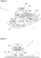
Figure 3 - is the perspective view of the connector group suitable to be used in the coffee maker related to an embodiment of the present invention. -
Figure 4 - is the front view of the connector group shown inFigure 3 . -
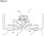
Figure 5 - is the cross-sectional view of the connector group provided at the base of the coffee maker related to an embodiment of the present invention. -
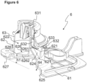
Figure 6 - is the partial cross-sectional perspective view showing the inner part of the connector group shown inFigure 3 . -
Figure 7 - is the view of the connector group shown inFigure 6 from a different angle. - The elements illustrated in the figures are numbered as follows:
- 1.
- Coffee maker
11. Brewing chamber
12. Coffee maker seating base - 2.
- Cable group
- 3.
- Brewing pot
31. Handle - 4.
- Body
- 5.
- Measuring spoon
- 6.
- Connector group
61. Connector group base
62. Lower connector part
621. Flow guiding surface
622. Inner part
623. Circumferential wall
624. Opposite protrusion
625. Skirt
626. Inner guiding fin
6261. First arm
6262. Second arm
6263. Open end part
627. Connector base
63. Upper connector part
631. Upper surface
632. Terminal end
633. Terminal protrusion - h1.
- First height
- h2.
- Second height
- Y
- Transverse cross-section of the connector group
- α
- Inclination angle
- The coffee maker (1) comprises a brewing pot (3) which has lateral surfaces and wherein the brewing process is performed; a brewing chamber (11) wherein the brewing pot (3) is placed; a heater which provides the heating of the brewing pot (3); a connector group (6) which is disposed at the bottom of the brewing chamber (11) and which is suitable for providing electrical connection with the brewing pot (3); and a control unit which controls the brewing process. Additional ingredients such as coffee and sugar placed in the brewing pot (3) are brewed by the heater with the water added depending on the amount of coffee desired to be brewed. On the brewing pot (3), there is an opposite connector receiver part which matches the connector group (6), and the necessary energy is supplied to the brewing pot (3) with the energy coming from the cable group (2) comprising the electrical cable.
- As shown in
Figure 1 and 2 , the coffee maker (1) of the present invention comprises an upper connector part (63) which is disposed in the brewing chamber (11) and which has terminal ends (632) therein, and a lower connector part (62) to which the upper connector part (63) is connected. Referring toFigure 3 , the connector group (6) has a terminal protrusion (633) which is disposed between each two terminal ends (632) and an opposite protrusion (624) which bears against each terminal end (633) in an aligned manner on the lower connector part (62). Thus, the possible connection between the terminal ends (632) in case of a possible leakage is prevented. In case of a possible overflow or unwanted liquid flow, said liquid is guided internally before reaching the terminal area. Even in case of liquid reaching the terminal area, the connection between the liquids and the terminals are prevented by means of the opposite protrusions (624) bearing against each terminal protrusion (633) in an aligned manner. Thus, a coffee maker (1) with improved safety is realized. The opposite protrusions (624) have substantially the same wall thickness as the terminal protrusions (633) and have a flat upper surface which bears against the terminal protrusions (633). - As shown in
Figure 2 , the brewing pot (3) comprises a pouring spout which is suitable for pouring the beverage therein after the completion of the brewing process, and a handle (31) which enables the user to hold the brewing pot (3). The coffee maker (1) further comprises a measuring spoon (5) which indicates the amount of coffee-like extract to be placed in the brewing pot (3) and which enables the same to be easily placed into the brewing pot (3). In the coffee maker (1), there are sensors which detect whether the coffee is foaming or not as well as a control card which cuts off the electricity to the heater after detection of the completion of the brewing of the coffee. Moreover, in an embodiment of the present invention, there may be additional sensors to inform the user audibly and visually. - The coffee maker (1) of the present invention comprises a flow guiding surface (621) which corresponds to each terminal end (632) and which is guided so as to be inclined towards the connector group base (61). Said flow guiding surface (621) is formed on the lower connector part (62). As shown in
Figure 3 , the flow guiding surface (621) having the opposite protrusions (624) thereon is configured to be inclined at an angle between 20° and 60° relative to the cross-section (Y) of the connector group (6). In an embodiment of the present invention, said flow guiding surface (621) is inclined at an angle of approximately 45°. Thus, the liquid which may reach the terminal ends (632) is also guided towards the connector group base (61). - In an embodiment of the present invention, the lower connector part (62) comprises an opening (64) which is formed at the base of the inner part (622) so as to allow liquid flow. As shown in
Figures 6 and7 , by means of the opening (64) having a larger diameter, the liquid guided into the connector group (6) is enabled to reach said opening (64) and be discharged out of the coffee maker (1). By configuring said opening (64) as wide as possible, problems such as clogging of the liquid flow in the smaller holes on the base are prevented. - In an embodiment of the present invention, the lower connector part (62) comprises an inner guiding fin (626) which is inclined towards the connector group base (61) at the inner part (622) so as to guide a liquid leak into the opening (64). Said inner guiding fin (626) extends in the lower connector part (62) and is inclined towards the opening (64). By means of the flow of the liquid, which may come from the upper surface (631) in the upper connector part (63), on said inner guiding fin (626), said liquid is enabled to flow quickly and safely to the opening (64). In an embodiment of the present invention, the inner guiding fin (626) comprises a first arm (6261) which contacts the upper connector part (63) and a second arm (6262) which extends towards the circumferential wall (623) forming the outer wall of the lower connector part (62) as an extension of said first arm (6261). As shown in
Figures 6 and7 , the first arm (6261) bears against the upper connector part (63) and extends downwards towards the opening (64) with a slight inclination close to the vertical direction. Here, the second arm (6262) extends at an angle greater than 90°. There is an inclination angle (α), preferably from 100° to 150°, between the first arm (6261) and the second arm (6262). Said inclination angle (α) and the height of the first arm (6261) are used to adjust the distance of the open end part (6263) of the first arm (6261) to the connector base (627). Referring toFigure 5 , the first distance (h1) of the open end part (6263) of the first arm (6261) to the connector base (627) is selected to be between 1/3 and 2/3 of the second distance (h2) of the open end part (6263) of the first arm (6261) to the coffee maker seating base (12). The critical point here is that the first distance (h1) should not be selected to be too close to the second distance (h2). Thus, the liquid guided by the inner guiding wing (626) is prevented from forming a connection after flowing into the opening (64). In case of a possible overflow, the liquid may accumulate in the opening (64), and by means of said specified distance, the liquid flowing last from the open end part (6263) is prevented from forming a connection with said accumulated liquid. Thus, a coffee maker (1) with improved safety is realized. Referring toFigure 5 , the part referred to as the coffee maker seating base (12) is the base part placed at the corners in contact with the surface whereon the coffee maker (1) is placed. In an alternative embodiment of the present invention, the height and form of the feet may change, or a flat base without any feet may be used. - As shown in
Figure 5 , in an embodiment of the present invention, the lower connector part (62) comprises an opening (64) which is formed at the connector base (627) and which has a diameter larger than the inner diameter of the lower connector part (62). By means of the larger diameter of said opening (64), clogging after possible accumulation of liquid is prevented. The part with a larger diameter is a skirt (625) which is an extension of the lower connector part (62) and which then joins with the connector group base (61). - As shown in
Figure 3 , in an embodiment of the present invention, the lower connector part (62) is a monolithic piece which is an extension of the connector group base (61). Thus, the production process is shortened and the production cost is also decreased. Moreover, there are a number of recessed parts which have the same cross-section on the connector group base (61). Said recesses also provide a more solid base structure.
Claims (10)
- A coffee maker (1) comprising a brewing pot (3) which has lateral surfaces and wherein the brewing process is performed; a brewing chamber (11) wherein the brewing pot (3) is placed; a heater which provides the heating of the brewing pot (3); a connector group (6) which is disposed at the bottom of the brewing chamber (11) and which is suitable for providing electrical connection with the brewing pot (3); and a control unit which controls the brewing process, characterized by the connector group (6) having- an upper connector part (63) which is disposed in the brewing chamber (11) and which has terminal ends (632) therein, and a lower connector part (62) to which the upper connector part (63) is connected;- a terminal protrusion (633) which is disposed between each two terminal ends (632); and- an opposite protrusion (624) which bears against each terminal end (633) in an aligned manner on the lower connector part (62).
- A coffee maker (1) as in Claim 1, characterized by the lower connector part (62) comprising a flow guiding surface (621) which corresponds to each terminal end (632) and which is guided so as to be inclined towards the connector group base (61).
- A coffee maker (1) as in Claim 2, characterized by the lower connector part (62) comprising the flow guiding surface (621) which is inclined with an angle between 20° and 60° relative to the cross-section (Y) of the connector group (6).
- A coffee maker (1) as in any one of the above claims, characterized by the lower connector part (62) comprising an opening (64) which is formed at the connector base (627) where the inner part (622) extends so as to allow liquid flow.
- A coffee maker (1) as in Claim 4, characterized by the lower connector part (62) comprising an inner guiding fin (626) which is inclined towards the connector group base (61) at the inner part (622) so as to guide a liquid leak into the opening (64).
- A coffee maker (1) as in Claim 5, characterized by the connector group (6) having the inner guiding fin (626) comprising a first arm (6261) which contacts the upper connector part (63) and a second arm (6262) which extends towards the circumferential wall (623) of the lower connector part (62) as an extension of said first arm (6261).
- A coffee maker (1) as in Claim 6, characterized by the connector group (6) comprising the inner guiding fin (626) having the first arm (6261) and the second arm (6262) with an inclination angle from 100° to 150° therebetween.
- A coffee maker (1) as in any one of the above claims, characterized by the inner guiding fin (626) wherein the first distance (h1) of the open end part (6263) of the first arm (6261) to the connector base (627) is selected to be between 1/3 and 2/3 of the second distance (h2) of the open end part (6263) of the first arm (6261) to the coffee maker seating base (12).
- A coffee maker (1) as in any one of the above claims, characterized by the lower connector part (62) comprising an opening (64) which is formed at the connector base (627) of the lower connector part (62) and which has a diameter larger than the inner diameter of the lower connector part (62).
- A coffee maker (1) as in any one of the above claims, characterized by the connector group (6) wherein the lower connector part (62) is a monolithic piece which is an extension of the connector group base (61).
Applications Claiming Priority (1)
| Application Number | Priority Date | Filing Date | Title |
|---|---|---|---|
| TR202221448 | 2022-12-29 |
Publications (2)
| Publication Number | Publication Date |
|---|---|
| EP4393354A1 true EP4393354A1 (en) | 2024-07-03 |
| EP4393354B1 EP4393354B1 (en) | 2025-10-08 |
Family
ID=89378678
Family Applications (1)
| Application Number | Title | Priority Date | Filing Date |
|---|---|---|---|
| EP23220158.2A Active EP4393354B1 (en) | 2022-12-29 | 2023-12-22 | A coffee maker comprising a connector group |
Country Status (1)
| Country | Link |
|---|---|
| EP (1) | EP4393354B1 (en) |
Citations (3)
| Publication number | Priority date | Publication date | Assignee | Title |
|---|---|---|---|---|
| WO2008012506A1 (en) * | 2006-07-26 | 2008-01-31 | Otter Controls Limited | Cordless electrical connector |
| WO2015102553A1 (en) * | 2014-01-03 | 2015-07-09 | Arzum Elektri̇kli̇ Ev Aletleri̇ San. Ve Ti̇c. A.Ş. | A turkish coffee machine |
| TR201602964U1 (en) | 2014-01-03 | 2017-01-23 | Arzum Elektrikli Ev Aletleri Sanayi Ve Ticaret Anonim Sirketi | A TURKISH COFFEE MACHINE |
-
2023
- 2023-12-22 EP EP23220158.2A patent/EP4393354B1/en active Active
Patent Citations (3)
| Publication number | Priority date | Publication date | Assignee | Title |
|---|---|---|---|---|
| WO2008012506A1 (en) * | 2006-07-26 | 2008-01-31 | Otter Controls Limited | Cordless electrical connector |
| WO2015102553A1 (en) * | 2014-01-03 | 2015-07-09 | Arzum Elektri̇kli̇ Ev Aletleri̇ San. Ve Ti̇c. A.Ş. | A turkish coffee machine |
| TR201602964U1 (en) | 2014-01-03 | 2017-01-23 | Arzum Elektrikli Ev Aletleri Sanayi Ve Ticaret Anonim Sirketi | A TURKISH COFFEE MACHINE |
Also Published As
| Publication number | Publication date |
|---|---|
| EP4393354B1 (en) | 2025-10-08 |
Similar Documents
| Publication | Publication Date | Title |
|---|---|---|
| US20240245255A1 (en) | Coffee machine and milk texturing device | |
| EP1589859B1 (en) | A coffee machine | |
| EP3157398B1 (en) | Automatic coffee maker and method of preparing a brewed beverage | |
| EP2887845B1 (en) | Coffee machine | |
| US20150359377A1 (en) | Single Cup Beverage Maker and Method of Using Same | |
| EP2292129B1 (en) | Brew through lid, assembly of a thermal carafe and a brew through lid as well as a coffee maker including such an assembly | |
| US20120070552A1 (en) | Methods and apparatuses for obtaining beverages | |
| EP1522245A1 (en) | Brewing apparatus hot water discharge head | |
| FI80374B (en) | FILTERKAFFEKOKARE. | |
| WO2004098360A1 (en) | Apparatus for making brewed coffee and the like | |
| JP2014524820A (en) | Centrifugal brewing machine with flow collection assembly | |
| JP6061931B2 (en) | Beverage collector for collecting liquid subjected to centrifugal force and centrifugal beverage machine using the collector | |
| CA2569699A1 (en) | Moka coffee pot | |
| EP3528672B1 (en) | Flow-optimized pour over coffee brewing system | |
| US4798222A (en) | Valve assembly particularly usable with a coffee brewing basket | |
| EP4393354B1 (en) | A coffee maker comprising a connector group | |
| US5619904A (en) | Automatic tea brewing device and tea pot receptacle | |
| CN219460890U (en) | Coffee machine | |
| EP1758490B1 (en) | A coffee machine | |
| CN217161768U (en) | Split type electric heating coffee pot | |
| EP3527114B1 (en) | A beverage preparation device having a level and cook sensor element | |
| EP1802221A2 (en) | Funnel insert for coffee cartridge | |
| WO1996033643A1 (en) | Automatic tea brewing device and tea pot receptacle | |
| WO2015102553A1 (en) | A turkish coffee machine | |
| EP1906799B1 (en) | A coffee machine |
Legal Events
| Date | Code | Title | Description |
|---|---|---|---|
| PUAI | Public reference made under article 153(3) epc to a published international application that has entered the european phase |
Free format text: ORIGINAL CODE: 0009012 |
|
| STAA | Information on the status of an ep patent application or granted ep patent |
Free format text: STATUS: REQUEST FOR EXAMINATION WAS MADE |
|
| 17P | Request for examination filed |
Effective date: 20231222 |
|
| AK | Designated contracting states |
Kind code of ref document: A1 Designated state(s): AL AT BE BG CH CY CZ DE DK EE ES FI FR GB GR HR HU IE IS IT LI LT LU LV MC ME MK MT NL NO PL PT RO RS SE SI SK SM TR |
|
| GRAP | Despatch of communication of intention to grant a patent |
Free format text: ORIGINAL CODE: EPIDOSNIGR1 |
|
| STAA | Information on the status of an ep patent application or granted ep patent |
Free format text: STATUS: GRANT OF PATENT IS INTENDED |
|
| RIC1 | Information provided on ipc code assigned before grant |
Ipc: A47J 27/21 20060101AFI20250425BHEP |
|
| INTG | Intention to grant announced |
Effective date: 20250509 |
|
| GRAS | Grant fee paid |
Free format text: ORIGINAL CODE: EPIDOSNIGR3 |
|
| GRAA | (expected) grant |
Free format text: ORIGINAL CODE: 0009210 |
|
| STAA | Information on the status of an ep patent application or granted ep patent |
Free format text: STATUS: THE PATENT HAS BEEN GRANTED |
|
| AK | Designated contracting states |
Kind code of ref document: B1 Designated state(s): AL AT BE BG CH CY CZ DE DK EE ES FI FR GB GR HR HU IE IS IT LI LT LU LV MC ME MK MT NL NO PL PT RO RS SE SI SK SM TR |
|
| REG | Reference to a national code |
Ref country code: GB Ref legal event code: FG4D Ref country code: CH Ref legal event code: F10 Free format text: ST27 STATUS EVENT CODE: U-0-0-F10-F00 (AS PROVIDED BY THE NATIONAL OFFICE) Effective date: 20251008 |
|
| REG | Reference to a national code |
Ref country code: DE Ref legal event code: R096 Ref document number: 602023007323 Country of ref document: DE |
|
| REG | Reference to a national code |
Ref country code: IE Ref legal event code: FG4D |
|
| PGFP | Annual fee paid to national office [announced via postgrant information from national office to epo] |
Ref country code: DE Payment date: 20251211 Year of fee payment: 3 |
|
| PGFP | Annual fee paid to national office [announced via postgrant information from national office to epo] |
Ref country code: AT Payment date: 20260113 Year of fee payment: 3 |
|
| PGFP | Annual fee paid to national office [announced via postgrant information from national office to epo] |
Ref country code: TR Payment date: 20251113 Year of fee payment: 3 Ref country code: GR Payment date: 20251222 Year of fee payment: 3 |
|
| REG | Reference to a national code |
Ref country code: GR Ref legal event code: EP Ref document number: 20250402405 Country of ref document: GR Effective date: 20260115 |
|
| REG | Reference to a national code |
Ref country code: NL Ref legal event code: MP Effective date: 20251008 |
|
| REG | Reference to a national code |
Ref country code: AT Ref legal event code: MK05 Ref document number: 1844140 Country of ref document: AT Kind code of ref document: T Effective date: 20251008 |
|
| PG25 | Lapsed in a contracting state [announced via postgrant information from national office to epo] |
Ref country code: NL Free format text: LAPSE BECAUSE OF FAILURE TO SUBMIT A TRANSLATION OF THE DESCRIPTION OR TO PAY THE FEE WITHIN THE PRESCRIBED TIME-LIMIT Effective date: 20251008 |
|
| PG25 | Lapsed in a contracting state [announced via postgrant information from national office to epo] |
Ref country code: ES Free format text: LAPSE BECAUSE OF FAILURE TO SUBMIT A TRANSLATION OF THE DESCRIPTION OR TO PAY THE FEE WITHIN THE PRESCRIBED TIME-LIMIT Effective date: 20251008 |
|
| REG | Reference to a national code |
Ref country code: LT Ref legal event code: MG9D |
|
| PG25 | Lapsed in a contracting state [announced via postgrant information from national office to epo] |
Ref country code: NO Free format text: LAPSE BECAUSE OF FAILURE TO SUBMIT A TRANSLATION OF THE DESCRIPTION OR TO PAY THE FEE WITHIN THE PRESCRIBED TIME-LIMIT Effective date: 20260108 |
|
| PG25 | Lapsed in a contracting state [announced via postgrant information from national office to epo] |
Ref country code: HR Free format text: LAPSE BECAUSE OF FAILURE TO SUBMIT A TRANSLATION OF THE DESCRIPTION OR TO PAY THE FEE WITHIN THE PRESCRIBED TIME-LIMIT Effective date: 20251008 Ref country code: FI Free format text: LAPSE BECAUSE OF FAILURE TO SUBMIT A TRANSLATION OF THE DESCRIPTION OR TO PAY THE FEE WITHIN THE PRESCRIBED TIME-LIMIT Effective date: 20251008 Ref country code: AT Free format text: LAPSE BECAUSE OF FAILURE TO SUBMIT A TRANSLATION OF THE DESCRIPTION OR TO PAY THE FEE WITHIN THE PRESCRIBED TIME-LIMIT Effective date: 20251008 |
|
| PG25 | Lapsed in a contracting state [announced via postgrant information from national office to epo] |
Ref country code: RS Free format text: LAPSE BECAUSE OF FAILURE TO SUBMIT A TRANSLATION OF THE DESCRIPTION OR TO PAY THE FEE WITHIN THE PRESCRIBED TIME-LIMIT Effective date: 20260108 |
|
| PG25 | Lapsed in a contracting state [announced via postgrant information from national office to epo] |
Ref country code: IS Free format text: LAPSE BECAUSE OF FAILURE TO SUBMIT A TRANSLATION OF THE DESCRIPTION OR TO PAY THE FEE WITHIN THE PRESCRIBED TIME-LIMIT Effective date: 20260208 |
|
| PG25 | Lapsed in a contracting state [announced via postgrant information from national office to epo] |
Ref country code: PT Free format text: LAPSE BECAUSE OF FAILURE TO SUBMIT A TRANSLATION OF THE DESCRIPTION OR TO PAY THE FEE WITHIN THE PRESCRIBED TIME-LIMIT Effective date: 20260209 |
|
| PG25 | Lapsed in a contracting state [announced via postgrant information from national office to epo] |
Ref country code: PL Free format text: LAPSE BECAUSE OF FAILURE TO SUBMIT A TRANSLATION OF THE DESCRIPTION OR TO PAY THE FEE WITHIN THE PRESCRIBED TIME-LIMIT Effective date: 20251008 |
|
| PG25 | Lapsed in a contracting state [announced via postgrant information from national office to epo] |
Ref country code: LV Free format text: LAPSE BECAUSE OF FAILURE TO SUBMIT A TRANSLATION OF THE DESCRIPTION OR TO PAY THE FEE WITHIN THE PRESCRIBED TIME-LIMIT Effective date: 20251008 |
|
| PG25 | Lapsed in a contracting state [announced via postgrant information from national office to epo] |
Ref country code: BG Free format text: LAPSE BECAUSE OF FAILURE TO SUBMIT A TRANSLATION OF THE DESCRIPTION OR TO PAY THE FEE WITHIN THE PRESCRIBED TIME-LIMIT Effective date: 20251008 |
|
| PG25 | Lapsed in a contracting state [announced via postgrant information from national office to epo] |
Ref country code: RO Free format text: LAPSE BECAUSE OF FAILURE TO SUBMIT A TRANSLATION OF THE DESCRIPTION OR TO PAY THE FEE WITHIN THE PRESCRIBED TIME-LIMIT Effective date: 20251008 |
|
| PG25 | Lapsed in a contracting state [announced via postgrant information from national office to epo] |
Ref country code: LT Free format text: LAPSE BECAUSE OF FAILURE TO SUBMIT A TRANSLATION OF THE DESCRIPTION OR TO PAY THE FEE WITHIN THE PRESCRIBED TIME-LIMIT Effective date: 20251008 |
|
| PG25 | Lapsed in a contracting state [announced via postgrant information from national office to epo] |
Ref country code: SM Free format text: LAPSE BECAUSE OF FAILURE TO SUBMIT A TRANSLATION OF THE DESCRIPTION OR TO PAY THE FEE WITHIN THE PRESCRIBED TIME-LIMIT Effective date: 20251008 |
|
| PG25 | Lapsed in a contracting state [announced via postgrant information from national office to epo] |
Ref country code: MC Free format text: LAPSE BECAUSE OF FAILURE TO SUBMIT A TRANSLATION OF THE DESCRIPTION OR TO PAY THE FEE WITHIN THE PRESCRIBED TIME-LIMIT Effective date: 20251008 |
|
| PG25 | Lapsed in a contracting state [announced via postgrant information from national office to epo] |
Ref country code: DK Free format text: LAPSE BECAUSE OF FAILURE TO SUBMIT A TRANSLATION OF THE DESCRIPTION OR TO PAY THE FEE WITHIN THE PRESCRIBED TIME-LIMIT Effective date: 20251008 |
|
| PG25 | Lapsed in a contracting state [announced via postgrant information from national office to epo] |
Ref country code: IT Free format text: LAPSE BECAUSE OF FAILURE TO SUBMIT A TRANSLATION OF THE DESCRIPTION OR TO PAY THE FEE WITHIN THE PRESCRIBED TIME-LIMIT Effective date: 20251008 |
|
| PG25 | Lapsed in a contracting state [announced via postgrant information from national office to epo] |
Ref country code: EE Free format text: LAPSE BECAUSE OF FAILURE TO SUBMIT A TRANSLATION OF THE DESCRIPTION OR TO PAY THE FEE WITHIN THE PRESCRIBED TIME-LIMIT Effective date: 20251008 |
|
| PG25 | Lapsed in a contracting state [announced via postgrant information from national office to epo] |
Ref country code: CZ Free format text: LAPSE BECAUSE OF FAILURE TO SUBMIT A TRANSLATION OF THE DESCRIPTION OR TO PAY THE FEE WITHIN THE PRESCRIBED TIME-LIMIT Effective date: 20251008 |
|
| PG25 | Lapsed in a contracting state [announced via postgrant information from national office to epo] |
Ref country code: SK Free format text: LAPSE BECAUSE OF FAILURE TO SUBMIT A TRANSLATION OF THE DESCRIPTION OR TO PAY THE FEE WITHIN THE PRESCRIBED TIME-LIMIT Effective date: 20251008 |
|
| PG25 | Lapsed in a contracting state [announced via postgrant information from national office to epo] |
Ref country code: SE Free format text: LAPSE BECAUSE OF FAILURE TO SUBMIT A TRANSLATION OF THE DESCRIPTION OR TO PAY THE FEE WITHIN THE PRESCRIBED TIME-LIMIT Effective date: 20251008 |
|
| PLBE | No opposition filed within time limit |
Free format text: ORIGINAL CODE: 0009261 |
|
| STAA | Information on the status of an ep patent application or granted ep patent |
Free format text: STATUS: NO OPPOSITION FILED WITHIN TIME LIMIT |