EP4393327A1 - Elastic conductive element, atomization assembly and assembly method therefor, and ultrasonic atomizer - Google Patents
Elastic conductive element, atomization assembly and assembly method therefor, and ultrasonic atomizer Download PDFInfo
- Publication number
- EP4393327A1 EP4393327A1 EP22891983.3A EP22891983A EP4393327A1 EP 4393327 A1 EP4393327 A1 EP 4393327A1 EP 22891983 A EP22891983 A EP 22891983A EP 4393327 A1 EP4393327 A1 EP 4393327A1
- Authority
- EP
- European Patent Office
- Prior art keywords
- electrical connection
- connection member
- electrode
- conductive element
- conductive tube
- Prior art date
- Legal status (The legal status is an assumption and is not a legal conclusion. Google has not performed a legal analysis and makes no representation as to the accuracy of the status listed.)
- Pending
Links
Images




Classifications
-
- A—HUMAN NECESSITIES
- A24—TOBACCO; CIGARS; CIGARETTES; SIMULATED SMOKING DEVICES; SMOKERS' REQUISITES
- A24F—SMOKERS' REQUISITES; MATCH BOXES; SIMULATED SMOKING DEVICES
- A24F40/00—Electrically operated smoking devices; Component parts thereof; Manufacture thereof; Maintenance or testing thereof; Charging means specially adapted therefor
- A24F40/40—Constructional details, e.g. connection of cartridges and battery parts
-
- A—HUMAN NECESSITIES
- A24—TOBACCO; CIGARS; CIGARETTES; SIMULATED SMOKING DEVICES; SMOKERS' REQUISITES
- A24F—SMOKERS' REQUISITES; MATCH BOXES; SIMULATED SMOKING DEVICES
- A24F40/00—Electrically operated smoking devices; Component parts thereof; Manufacture thereof; Maintenance or testing thereof; Charging means specially adapted therefor
- A24F40/05—Devices without heating means
-
- A—HUMAN NECESSITIES
- A24—TOBACCO; CIGARS; CIGARETTES; SIMULATED SMOKING DEVICES; SMOKERS' REQUISITES
- A24F—SMOKERS' REQUISITES; MATCH BOXES; SIMULATED SMOKING DEVICES
- A24F40/00—Electrically operated smoking devices; Component parts thereof; Manufacture thereof; Maintenance or testing thereof; Charging means specially adapted therefor
- A24F40/10—Devices using liquid inhalable precursors
-
- A—HUMAN NECESSITIES
- A24—TOBACCO; CIGARS; CIGARETTES; SIMULATED SMOKING DEVICES; SMOKERS' REQUISITES
- A24F—SMOKERS' REQUISITES; MATCH BOXES; SIMULATED SMOKING DEVICES
- A24F40/00—Electrically operated smoking devices; Component parts thereof; Manufacture thereof; Maintenance or testing thereof; Charging means specially adapted therefor
- A24F40/70—Manufacture
-
- A—HUMAN NECESSITIES
- A61—MEDICAL OR VETERINARY SCIENCE; HYGIENE
- A61M—DEVICES FOR INTRODUCING MEDIA INTO, OR ONTO, THE BODY; DEVICES FOR TRANSDUCING BODY MEDIA OR FOR TAKING MEDIA FROM THE BODY; DEVICES FOR PRODUCING OR ENDING SLEEP OR STUPOR
- A61M15/00—Inhalators
- A61M15/0085—Inhalators using ultrasonics
-
- B—PERFORMING OPERATIONS; TRANSPORTING
- B05—SPRAYING OR ATOMISING IN GENERAL; APPLYING FLUENT MATERIALS TO SURFACES, IN GENERAL
- B05B—SPRAYING APPARATUS; ATOMISING APPARATUS; NOZZLES
- B05B17/00—Apparatus for spraying or atomising liquids or other fluent materials, not covered by the preceding groups
- B05B17/04—Apparatus for spraying or atomising liquids or other fluent materials, not covered by the preceding groups operating with special methods
- B05B17/06—Apparatus for spraying or atomising liquids or other fluent materials, not covered by the preceding groups operating with special methods using ultrasonic or other kinds of vibrations
-
- B—PERFORMING OPERATIONS; TRANSPORTING
- B05—SPRAYING OR ATOMISING IN GENERAL; APPLYING FLUENT MATERIALS TO SURFACES, IN GENERAL
- B05B—SPRAYING APPARATUS; ATOMISING APPARATUS; NOZZLES
- B05B17/00—Apparatus for spraying or atomising liquids or other fluent materials, not covered by the preceding groups
- B05B17/04—Apparatus for spraying or atomising liquids or other fluent materials, not covered by the preceding groups operating with special methods
- B05B17/06—Apparatus for spraying or atomising liquids or other fluent materials, not covered by the preceding groups operating with special methods using ultrasonic or other kinds of vibrations
- B05B17/0607—Apparatus for spraying or atomising liquids or other fluent materials, not covered by the preceding groups operating with special methods using ultrasonic or other kinds of vibrations generated by electrical means, e.g. piezoelectric transducers
- B05B17/0615—Apparatus for spraying or atomising liquids or other fluent materials, not covered by the preceding groups operating with special methods using ultrasonic or other kinds of vibrations generated by electrical means, e.g. piezoelectric transducers spray being produced at the free surface of the liquid or other fluent material in a container and subjected to the vibrations
-
- B—PERFORMING OPERATIONS; TRANSPORTING
- B05—SPRAYING OR ATOMISING IN GENERAL; APPLYING FLUENT MATERIALS TO SURFACES, IN GENERAL
- B05B—SPRAYING APPARATUS; ATOMISING APPARATUS; NOZZLES
- B05B17/00—Apparatus for spraying or atomising liquids or other fluent materials, not covered by the preceding groups
- B05B17/04—Apparatus for spraying or atomising liquids or other fluent materials, not covered by the preceding groups operating with special methods
- B05B17/06—Apparatus for spraying or atomising liquids or other fluent materials, not covered by the preceding groups operating with special methods using ultrasonic or other kinds of vibrations
- B05B17/0607—Apparatus for spraying or atomising liquids or other fluent materials, not covered by the preceding groups operating with special methods using ultrasonic or other kinds of vibrations generated by electrical means, e.g. piezoelectric transducers
- B05B17/0653—Details
Definitions
- Embodiments of this application relate to the field of atomization technologies, and in particular, to an elastic conductive element, an atomization assembly and an assembly method therefor, and an ultrasonic atomizer.
- An ultrasonic atomizer includes an ultrasonic atomization sheet.
- the ultrasonic atomization sheet is provided with micropores.
- a liquid matrix in the micropores can be atomized to form liquid mist.
- the liquid mist is squirted from the micropores to be inhaled by a user.
- the existence of the resistance board leads to many parts, many processes, and high costs of the ultrasonic atomizer, and the resistance board is fixedly and conductively connected to the electrode on the upper surface and the electrode on the lower surface of the ultrasonic atomization sheet by screws or solder, and is prone to poor soldering and other infirm fixation problems.
- An aspect of this application provides an atomization assembly, including:
- Another aspect of this application provides an ultrasonic atomizer, including a liquid storage cavity for storing a liquid matrix, and the foregoing atomization assembly.
- the elastic conductive element, the atomization assembly and the assembly method therefor, the ultrasonic atomizer, and the ultrasonic atomization apparatus provided in this application, energy stored by the ultrasonic atomization sheet after being powered on and then powered off is consumed and vibration transmission of the ultrasonic atomization sheet is reduced through the elastic conductive element, so that a resistance board does not need to be additionally provided, thereby reducing parts and costs of the atomization assembly, and saving a structural space of the atomization assembly.
- the ultrasonic atomization apparatus 100 includes an ultrasonic atomizer 10 and a power supply assembly 20, and the ultrasonic atomizer 10 and the power supply assembly 20 are non-detachable.
- the ultrasonic atomizer 10 includes a liquid storage cavity (not shown in the accompanying drawing) for storing a liquid matrix, and an atomization assembly 11, and the atomization assembly 11 generates high-frequency oscillation under the action of power provided by the power supply assembly 20, so that the liquid matrix is atomized into liquid mist.
- the power supply assembly 20 includes a cell 21 and a circuit 22.
- the cell 21 supplies power for operating the ultrasonic atomization apparatus 100.
- the cell 21 may be a rechargeable cell or a disposable cell.
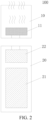
- FIG. 2 is a schematic diagram of another ultrasonic atomization apparatus according to an implementation of this application. Different from the example in FIG. 1 , an ultrasonic atomizer 10 is detachably connected to a power supply assembly 20.
- the ultrasonic atomization sheet 111 includes a piezoelectric ceramic matrix, and the piezoelectric ceramic matrix is roughly circular, and has an upper surface on which a first electrode 11 1a is formed and a lower surface on which a second electrode 111b is formed.
- d1 ranges from 5 mm to 6 mm; or ranges from 5.2 mm to 6 mm; or ranges from 5.4 mm to 6 mm; or ranges from 5.5 mm to 6 mm.
- the elastic conductive element 113 may be electrically connected to the first electrode 111a and the second electrode 111b on one side of the ultrasonic atomization sheet 111; or the elastic conductive element 113 may be electrically connected to the first electrode 111a on one side and electrically connected to the second electrode 111b on the other side in a manner of wrapping the ultrasonic atomization sheet 111.
- the elastic conductive element 113 directly maintains contact with the first electrode 111a thereby forming electrical connection, and the elastic conductive element 113 directly maintains contact with the second electrode 111b thereby forming electrical connection. Further, the elastic conductive element 113 maintains contact with both the first electrode 111a and the first electrical connection member thereby forming electrical connection, and the elastic conductive element 113 maintains contact with both the second electrode 111b and the second electrical connection member 114 thereby forming electrical connection, which is also feasible.
- the assembly method includes:
- the second electrical connection member may be first mounted in the conductive tube, and then the elastic conductive element is mounted in the conductive tube; or the second electrical connection member and the elastic conductive element that are assembled are mounted in the conductive tube together.
Landscapes
- Health & Medical Sciences (AREA)
- Engineering & Computer Science (AREA)
- Bioinformatics & Cheminformatics (AREA)
- Pulmonology (AREA)
- Anesthesiology (AREA)
- Biomedical Technology (AREA)
- Heart & Thoracic Surgery (AREA)
- Hematology (AREA)
- Life Sciences & Earth Sciences (AREA)
- Animal Behavior & Ethology (AREA)
- General Health & Medical Sciences (AREA)
- Public Health (AREA)
- Veterinary Medicine (AREA)
- Special Spraying Apparatus (AREA)
Abstract
Description
- This application claims priority to
Chinese Patent Application No. 202111319770.9, entitled "ELASTIC CONDUCTIVE ELEMENT, ATOMIZATION ASSEMBLY AND ASSEMBLY METHOD THEREFOR, AND ULTRASONIC ATOMIZER" and filed with the China National Intellectual Property Administration on November 09, 2021 - Embodiments of this application relate to the field of atomization technologies, and in particular, to an elastic conductive element, an atomization assembly and an assembly method therefor, and an ultrasonic atomizer.
- An ultrasonic atomizer includes an ultrasonic atomization sheet. The ultrasonic atomization sheet is provided with micropores. When the ultrasonic atomization sheet generates high-frequency vibration, a liquid matrix in the micropores can be atomized to form liquid mist. The liquid mist is squirted from the micropores to be inhaled by a user.
- A resistance board is connected between an electrode on an upper surface and an electrode on a lower surface of the existing ultrasonic atomization sheet, so that after the ultrasonic atomizer is powered off, the ultrasonic atomization sheet and a resistor on the resistance board form a closed circuit, which can consume, after being powered on and then powered off, energy stored in the ultrasonic atomization sheet itself, to avoid a case that an instantaneous high voltage is released to burn out other electronic components after the ultrasonic atomization sheet is powered on again, to ensure that the ultrasonic atomization sheet can work normally after being powered on again.
- The existence of the resistance board leads to many parts, many processes, and high costs of the ultrasonic atomizer, and the resistance board is fixedly and conductively connected to the electrode on the upper surface and the electrode on the lower surface of the ultrasonic atomization sheet by screws or solder, and is prone to poor soldering and other infirm fixation problems.
- This application provides an elastic conductive element, an atomization assembly and an assembly method therefor, an ultrasonic atomizer, and an ultrasonic atomization apparatus, aiming to resolve problems of many parts and high costs of the existing ultrasonic atomizer.
- An aspect of this application provides an atomization assembly, including:
- an ultrasonic atomization sheet provided with a first electrode and a second electrode, where the ultrasonic atomization sheet is used for ultrasonically atomizing a liquid matrix to form liquid mist; and
- an elastic conductive element, which is in elastic contact with the ultrasonic atomization sheet to support the ultrasonic atomization sheet, where
- one area of the elastic conductive element is directly or indirectly electrically connected to the first electrode, and the other area of the elastic conductive element is directly or indirectly electrically connected to the second electrode, to form a loop among the first electrode, the elastic conductive element, and the second electrode.
- Another aspect of this application provides an ultrasonic atomizer, including a liquid storage cavity for storing a liquid matrix, and the foregoing atomization assembly.
- Another aspect of this application further provides an assembly method for an atomization assembly. The assembly method includes:
- providing a conductive tube, where a first end of the conductive tube is provided with a first extending portion extending radially toward a center of the conductive tube;
- mounting an ultrasonic atomization sheet in the conductive tube, where a first electrode of the ultrasonic atomization sheet abuts against the first extending portion; and
- mounting a second electrical connection member and an elastic conductive element in the conductive tube, where the second electrical connection member abuts against a second electrode of the ultrasonic atomization sheet, and the elastic conductive element abuts against the ultrasonic atomization sheet.
- Another aspect of this application further provides an assembly method for an atomization assembly. The assembly method includes:
- providing a conductive tube, where a second end of the conductive tube is provided with a second extending portion extending radially toward a center of the conductive tube;
- mounting a second electrical connection member and an elastic conductive element in the conductive tube, where the elastic conductive element abuts against the second extending portion, and the elastic conductive element spaces the conduit tube apart from the second electrical connection member;
- mounting an ultrasonic atomization sheet in the conductive tube, where a first electrode of the ultrasonic atomization sheet abuts against the second electrical connection member; and
- performing a bending operation on the second end of the conductive tube, to cause the first end to form a first extending portion extending radially toward the center of the conductive tube, where the first extending portion is connected to the first electrode of the ultrasonic atomization sheet.
- Another aspect of this application further provides an elastic conductive element, including: a cylindrical body, where the cylindrical body includes a proximal end, a distal end, and a hollow part extending from the proximal end to the distal end;
the proximal end is at least partially used for coming into elastic contact with an ultrasonic atomization sheet to support the ultrasonic atomization sheet; the hollow part is used for accommodating a second electrical connection member, to fix the second electrical connection member, and an inner wall of the hollow part is at least partially in contact with the second electrical connection member to form electrical connection; and an outer wall of the cylindrical body is in contact with a first electrical connection member, to form electrical connection. - According to the elastic conductive element, the atomization assembly and the assembly method therefor, the ultrasonic atomizer, and the ultrasonic atomization apparatus provided in this application, energy stored by the ultrasonic atomization sheet after being powered on and then powered off is consumed and vibration transmission of the ultrasonic atomization sheet is reduced through the elastic conductive element, so that a resistance board does not need to be additionally provided, thereby reducing parts and costs of the atomization assembly, and saving a structural space of the atomization assembly.
- One or more embodiments are exemplarily described with reference to the corresponding figures in the accompanying drawings, and the descriptions are not to be construed as limiting the embodiments. Elements in the accompanying drawings that have same reference numerals are represented as similar elements, and unless otherwise particularly stated, the figures in the accompanying drawings are not drawn to scale.
-
FIG. 1 is a schematic diagram of an ultrasonic atomization apparatus according to an implementation of this application; -
FIG. 2 is a schematic diagram of another ultrasonic atomization apparatus according to an implementation of this application; -
FIG. 3 is a schematic diagram of an atomization assembly according to an implementation of this application; -
FIG. 4 is a schematic cross-sectional view of an atomization assembly according to an implementation of this application; -
FIG. 5 is a schematic exploded view of an atomization assembly according to an implementation of this application; -
FIG. 6 is a schematic diagram of an ultrasonic atomization sheet according to an implementation of this application; -
FIG. 7 is a schematic diagram of an ultrasonic atomization sheet according to an implementation of this application from another perspective; and -
FIG. 8 is a schematic diagram of an elastic conductive element according to an implementation of this application from another perspective. - For ease of understanding this application, this application is described in more detail below with reference to the accompanying drawings and specific embodiments. It should be noted that, when an element is expressed as "being fixed to" another element, the element may be directly on the another element, or one or more intermediate elements may exist between the element and the another element. When an element is expressed as "being connected to" another element, the element may be directly connected to the another element, or one or more intermediate elements may exist between the element and the another element. The terms "upper", "lower", "left", "right", "inner", "outer", and similar expressions used in this specification are merely used for an illustrative purpose.
- Unless otherwise defined, meanings of all technical and scientific terms used in this specification are the same as that usually understood by a person skilled in the art to which this application belongs. The terms used in this specification of this application are merely intended to describe objectives of the specific implementations, and are not intended to limit this application. The term "and/or" used in this specification includes any or all combinations of one or more related listed items.
-
FIG. 1 is a schematic diagram of an ultrasonic atomization apparatus according to an implementation of this application. - As shown in
FIG. 1 , theultrasonic atomization apparatus 100 includes anultrasonic atomizer 10 and apower supply assembly 20, and theultrasonic atomizer 10 and thepower supply assembly 20 are non-detachable. - The
ultrasonic atomizer 10 includes a liquid storage cavity (not shown in the accompanying drawing) for storing a liquid matrix, and anatomization assembly 11, and theatomization assembly 11 generates high-frequency oscillation under the action of power provided by thepower supply assembly 20, so that the liquid matrix is atomized into liquid mist. - The
power supply assembly 20 includes acell 21 and acircuit 22. - The
cell 21 supplies power for operating theultrasonic atomization apparatus 100. Thecell 21 may be a rechargeable cell or a disposable cell. - The
circuit 22 may control overall operations of theultrasonic atomization apparatus 100. Thecircuit 22 not only controls operations of thecell 21 and theatomization assembly 11, but also controls operations of other components in theultrasonic atomization apparatus 100. -
FIG. 2 is a schematic diagram of another ultrasonic atomization apparatus according to an implementation of this application. Different from the example inFIG. 1 , anultrasonic atomizer 10 is detachably connected to apower supply assembly 20. - As shown in
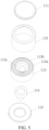
FIG. 3 to FIG. 7 , an implementation of this application provides anatomization assembly 11, including anultrasonic atomization sheet 111, a first electrical connection member (112, 115), an elasticconductive element 113, and a secondelectrical connection member 114. - In this example, the
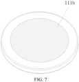
ultrasonic atomization sheet 111 includes a piezoelectric ceramic matrix, and the piezoelectric ceramic matrix is roughly circular, and has an upper surface on which afirst electrode 11 1a is formed and a lower surface on which asecond electrode 111b is formed. - The first electrical connection member (112, 115) includes a
conductive tube 112 and acoupling member 115. Theultrasonic atomization sheet 111, the elasticconductive element 113, and the secondelectrical connection member 114 are each arranged in theconductive tube 112. Specifically, theultrasonic atomization sheet 111 is horizontally arranged close to an upper end (a first end) of theconductive tube 112, the elasticconductive element 113 and the secondelectrical connection member 114 are arranged between theultrasonic atomization sheet 111 and a lower end (a second end) of theconductive tube 112, and theconductive tube 112 is spaced apart from the secondelectrical connection member 114 through the elasticconductive element 113. - One area of the elastic
conductive element 113 is directly or indirectly electrically connected to thefirst electrode 111a of theultrasonic atomization sheet 111, and the other area of the elasticconductive element 113 is directly or indirectly electrically connected to thesecond electrode 111b, to form a loop among thefirst electrode 111a, the elasticconductive element 113, and thesecond electrode 111b. It should be noted that the one area and the other area of the elasticconductive element 113 may be any two areas or parts in the elasticconductive element 113, as long as a case that thefirst electrode 111a is directly in contact with thesecond electrode 111b to cause short circuit is avoided. - In a preferred implementation, as shown in
FIG. 5 andFIG. 8 , the elasticconductive element 113 is constructed into a cylindrical structural, that is, includes a cylindrical body, anupper end 113a (proximal end) of the cylindrical body is provided with a plurality of protrudingportions 113b, the protrudingportions 113b are ring-shaped, and the plurality of ring-shaped protrudingportions 113b are arranged along the radial direction. Alower end 113d (distal end) of the cylindrical body is provided with a part extending axially downward, to form aboss 113e. A hollow part of the cylindrical body forms anaccommodating chamber 113c, and theaccommodating chamber 113c extends from theupper end 113a to thelower end 113d; and theaccommodating chamber 113c matches the secondelectrical connection member 114 in shape, and is used for accommodating the secondelectrical connection member 114, to fix the secondelectrical connection member 114. The protrudingportion 113b abuts against a lower surface of theultrasonic atomization sheet 111, to support theultrasonic atomization sheet 111. A sidewall of the elasticconductive element 113 at least partially abuts against an inner wall of theconductive tube 112, to form electrical connection. - The elastic
conductive element 113 is made of a mixture of an elastic material and metal particles, and the elastic material may be silicone, soft rubber, or the like. In this way, the elasticconductive element 113 itself has specific resistance, whose resistance value is greater than 500 KS2; or is greater than 800 KS2; or is greater than 1 MΩ; or is greater than 1 MΩ and less than 2 MS2. The elasticconductive element 113 reduces vibration transmission of theultrasonic atomization sheet 111 through its own elasticity in an aspect; and maintains contact with both the first electrical connection member and the secondelectrical connection member 114 to form electrical connection in another aspect, thereby forming a loop to consume energy stored in theultrasonic atomization sheet 111 itself after being powered on and then powered off, to ensure that theultrasonic atomization sheet 111 can work normally after being powered on again, and avoid a case that an instantaneous high voltage is released to burn out other electronic components after theultrasonic atomization sheet 111 is powered on again. Because the resistance of the elasticconductive element 113 itself is large, while the resistance of theultrasonic atomization sheet 111 is small, the elasticconductive element 113 consumes very little energy when theultrasonic wave atomization 111 works. It may be understood that the elasticconductive element 113 further has a sealing effect, and can prevent the liquid matrix from leaking or flowing toward thelower end 113d in the cylindrical body because of maintaining contact with the lower surface of theultrasonic atomization sheet 111 and the inner wall of theconductive tube 112. - In this example, because the elastic
conductive element 113 is adopted, and no resistance board is additionally arranged, the distance d1 between the upper end and the lower end of theconductive tube 112 is much less than that in the existing solution. Usually, d1 ranges from 5 mm to 6 mm; or ranges from 5.2 mm to 6 mm; or ranges from 5.4 mm to 6 mm; or ranges from 5.5 mm to 6 mm. - The lower surface of the
ultrasonic atomization sheet 111 faces the secondelectrical connection member 114. In this way, one end of the secondelectrical connection member 114 abuts against thesecond electrode 111b formed on the lower surface of theultrasonic atomization sheet 111 to maintain contact thereby forming electrical connection, and the other end of the secondelectrical connection member 114 extends toward the lower end of theconductive tube 112. The upper end of theconductive tube 112 is provided with an extending portion (not shown in the accompanying drawing) that extends radially, and the extending portion abuts against thefirst electrode 111a formed on the upper surface of theultrasonic atomization sheet 111 to maintain contact thereby forming electrical connection. - It should be noted that the
first electrode 111a and thesecond electrode 111b on theultrasonic atomization sheet 111 are not limited to the situation in the accompanying drawing. In another example, thefirst electrode 111a and thesecond electrode 111b may be arranged on two sides of theultrasonic atomization sheet 111 separately, or may be arranged on one side, or may be arranged on the same surface of the ultrasonic atomization sheet 111 (for example, both arranged on the lower surface of the ultrasonic atomization sheet 111). As positions of thefirst electrode 111a and thesecond electrode 111b change, structures of the elasticconductive element 113, the first electrical connection member (112, 115), and the secondelectrical connection member 114 may also correspondingly change. For example, the elasticconductive element 113 may be electrically connected to thefirst electrode 111a and thesecond electrode 111b on one side of theultrasonic atomization sheet 111; or the elasticconductive element 113 may be electrically connected to thefirst electrode 111a on one side and electrically connected to thesecond electrode 111b on the other side in a manner of wrapping theultrasonic atomization sheet 111. - The
coupling member 115 is arranged close to the lower end of theconductive tube 112 and is maintained on theboss 113e. Thecoupling member 115 is ring-shaped and may be socketed on theboss 113e, and thecoupling member 115 maintains contact with theconductive tube 112 to form electrical connection. In this way, when theatomization assembly 11 is coupled to thecell 21, a lead may be advantageously soldered to thecoupling member 115 and the other end of the secondelectrical connection member 114. - In the examples of
FIG. 3 to FIG. 8 , the first electrical connection member (112, 115) includes theconductive tube 112 and thecoupling member 115, that is, the first electrical connection member is formed by two or more separate members. Different from the examples ofFIG. 3 to FIG. 8 , in another example, the first electrical connection member is realized by one structural member or an integrally formed structural member, which is also feasible. - In the examples of
FIG. 3 to FIG. 8 , the elasticconductive element 113 maintains contact with the first electrical connection member to form electrical connection, and the elasticconductive element 113 maintains contact with the secondelectrical connection member 114 to form electrical connection, that is, indirectly electrically connected to thefirst electrode 111a through the first electrical connection member, and indirectly electrically connected to thesecond electrode 111b through the secondelectrical connection member 114. Different from the examples ofFIG. 3 to FIG. 8 , in another example, the elasticconductive element 113 does not maintain contact with the first electrical connection member, and the elasticconductive element 113 does not maintain contact with the secondelectrical connection member 114, which is also feasible. Specifically, the elasticconductive element 113 directly maintains contact with thefirst electrode 111a thereby forming electrical connection, and the elasticconductive element 113 directly maintains contact with thesecond electrode 111b thereby forming electrical connection. Further, the elasticconductive element 113 maintains contact with both thefirst electrode 111a and the first electrical connection member thereby forming electrical connection, and the elasticconductive element 113 maintains contact with both thesecond electrode 111b and the secondelectrical connection member 114 thereby forming electrical connection, which is also feasible. - In the examples of
FIG. 3 to FIG. 8 , theatomization assembly 11 formed by theultrasonic atomization sheet 111, the first electrical connection member (112, 115), the elasticconductive element 113, and the secondelectrical connection member 114 is arranged in the ultrasonic atomizer 10 (detachable or non-detachable from the power supply assembly 20). Different from the examples ofFIG. 3 to FIG. 8 , in another example, theatomization assembly 11 formed by theultrasonic atomization sheet 111 and the elasticconductive element 113 may be arranged in the ultrasonic atomizer 10 (detachable or non-detachable from the power supply assembly 20); and the first electrical connection member (112, 115) and the secondelectrical connection member 114 are arranged in thepower supply assembly 20, which is also feasible. In this case, the first electrical connection member (112, 115) and the secondelectrical connection member 114 may be electrically connected to the electrodes in the ultrasonic atomization sheet directly or indirectly. - Another implementation of this application further provides an assembly method for an atomization assembly. The assembly method includes:
- Step S11. Provide a conductive tube, where a first end of the conductive tube is provided with a first extending portion extending radially toward a center of the conductive tube.
- Step S12. Mount an ultrasonic atomization sheet in the conductive tube, where a first electrode of the ultrasonic atomization sheet abuts against the first extending portion.
- Step S13. Mount a second electrical connection member and an elastic conductive element in the conductive tube, where the second electrical connection member abuts against a second electrode of the ultrasonic atomization sheet, and the elastic conductive element abuts against the ultrasonic atomization sheet.
- In this step, the second electrical connection member may be first mounted in the conductive tube, and then the elastic conductive element is mounted in the conductive tube; or the second electrical connection member and the elastic conductive element that are assembled are mounted in the conductive tube together.
- In an example, after the mounting a second electrical connection member and an elastic conductive element in the conductive tube, the assembly method further includes:
mounting a coupling member in the conductive tube, where the coupling member separately abuts against an inner wall of the conductive tube and the elastic conductive element. - In an example, after the mounting a second electrical connection member and an elastic conductive element in the conductive tube, the assembly method further includes:
bending the second end of the conductive tube, to cause the second end to form a second extending portion extending radially toward the center of the conductive tube. - In this example, the second extending portion formed by bending the second end of the conductive tube is functionally similar to the
coupling member 115 in the examples ofFIG. 3 to FIG. 8 . - Another implementation of this application further provides an assembly method for an atomization assembly. The assembly method includes:
Step S21. Provide a conductive tube, where a second end of the conductive tube is provided with a second extending portion extending radially toward a center of the conductive tube. - In this step, the second extending portion of the second end is functionally similar to the
coupling member 115 in the examples ofFIG. 3 to FIG. 8 . - Step S22. Mount a second electrical connection member and an elastic conductive element in the conductive tube, where the elastic conductive element abuts against the second extending portion, and the elastic conductive element spaces the conduit tube apart from the second electrical connection member.
- In this step, the second electrical connection member may be first mounted in the conductive tube, and then the elastic conductive element is mounted in the conductive tube; or the second electrical connection member and the elastic conductive element that are assembled are mounted in the conductive tube together.
- Step S23. Mount an ultrasonic atomization sheet in the conductive tube, where a first electrode of the ultrasonic atomization sheet abuts against the second electrical connection member.
- Step S24. Perform a bending operation on the second end of the conductive tube, to cause the first end to form a first extending portion extending radially toward the center of the conductive tube, where the first extending portion is connected to the first electrode of the ultrasonic atomization sheet.
- It should be noted that the specification of this application and the accompanying drawings thereof illustrate preferred embodiments of this application. However, this application may be implemented in various different forms, and is not limited to the embodiments described in this specification. These embodiments are not intended to be an additional limitation on the content of this application, and are described for the purpose of providing a more thorough and comprehensive understanding of the content disclosed in this application. Moreover, the foregoing technical features are further combined to form various embodiments not listed above, and all such embodiments shall be construed as falling within the scope of this application. Further, a person of ordinary skill in the art may make improvements or modifications according to the foregoing description, and all the improvements and modifications shall fall within the protection scope of the attached claims of this application.
Claims (16)
- An atomization assembly, comprising:an ultrasonic atomization sheet provided with a first electrode and a second electrode, wherein the ultrasonic atomization sheet is used for ultrasonically atomizing a liquid matrix to form liquid mist; andan elastic conductive element, which is in elastic contact with the ultrasonic atomization sheet to support the ultrasonic atomization sheet, whereinone area of the elastic conductive element is directly or indirectly electrically connected to the first electrode, and the other area of the elastic conductive element is directly or indirectly electrically connected to the second electrode, to form a loop among the first electrode, the elastic conductive element, and the second electrode.
- The atomization assembly according to claim 1, wherein a resistance value of the elastic conductive element is greater than 500 KS2; or a resistance value of the elastic conductive element is greater than 800 KS2; or a resistance value of the elastic conductive element is greater than 1 MΩ.
- The atomization assembly according to claim 1, wherein the atomization assembly further comprises a first electrical connection member in contact with the first electrode, and/or a second electrical connection member in contact with the second electrode;the elastic conductive element is in contact with the first electrical connection member, to be indirectly electrically connected to the first electrode through the first electrical connection member; andthe elastic conductive element is in contact with the second electrical connection member, to be indirectly electrically connected to the second electrode through the second electrical connection member.
- The atomization assembly according to claim 3, wherein the first electrical connection member comprises a conductive tube, and the conductive tube is electrically connected to the first electrode; and
the ultrasonic atomization sheet, the second electrical connection member, and the elastic conductive element are each arranged in the conductive tube, and the conductive tube is spaced apart from the second electrical connection member through the elastic conductive element. - The atomization assembly according to claim 4, wherein the conductive tube is provided with a first end and a second end opposite to the first end; and
a distance from the first end to the second end ranges from 5 mm to 6 mm; or ranges from 5.2 mm to 6 mm; or ranges from 5.4 mm to 6 mm; or ranges from 5.5 mm to 6 mm. - The atomization assembly according to claim 4, wherein the conductive tube is provided with a first end and a second end opposite to the first end; andthe ultrasonic atomization sheet is provided with a first surface used for arranging the first electrode and a second surface used for arranging the second electrode;the first end is provided with an extending portion extending toward a radial direction in the conductive tube, and the extending portion is in contact with the first surface of the ultrasonic atomization sheet and abuts against the first electrode to form electrical connection; andthe second electrical connection member is in contact with the second surface of the ultrasonic atomization sheet and abuts against the second electrode to form electrical connection.
- The atomization assembly according to claim 4, wherein the elastic conductive element is constructed into a cylindrical body; a hollow part of the cylindrical body is used for accommodating the second electrical connection member, to fix the second electrical connection member; and an inner wall of the hollow part is at least partially in contact with the second electrical connection member, and an outer wall of the cylindrical body is at least partially in contact with an inner wall of the conductive tube.
- The atomization assembly according to claim 4, wherein the conductive tube is provided with a first end and a second end opposite to the first end; and
the first electrical connection member further comprises a coupling member arranged close to the second end, and the coupling member maintains contact with the conductive tube to form electrical connection. - The atomization assembly according to claim 8, wherein the elastic conductive element is provided with a boss close to the second end; and the coupling member is ring-shaped, and the coupling member is sleeved on the boss and is spaced apart from the second connection member through the boss.
- The atomization assembly according to claim 1, wherein the elastic conductive element is made of at least a mixture of an elastic material and metal particles.
- An ultrasonic atomizer, comprising a liquid storage cavity for storing a liquid matrix, and the atomization assembly according to any one of claims 1 to 10.
- An assembly method for an atomization assembly, wherein the assembly method comprises:providing a conductive tube, wherein a first end of the conductive tube is provided with a first extending portion extending radially toward a center of the conductive tube;mounting an ultrasonic atomization sheet in the conductive tube, wherein a first electrode of the ultrasonic atomization sheet abuts against the first extending portion; andmounting a second electrical connection member and an elastic conductive element in the conductive tube, wherein the second electrical connection member abuts against a second electrode of the ultrasonic atomization sheet, and the elastic conductive element abuts against the ultrasonic atomization sheet.
- The assembly method according to claim 12, wherein after the mounting a second electrical connection member and an elastic conductive element in the conductive tube, the assembly method further comprises:
mounting a coupling member in the conductive tube, wherein the coupling member separately abuts against an inner wall of the conductive tube and the elastic conductive element. - The assembly method according to claim 12, wherein the conductive tube is provided with a second end opposite to the first end; and after the mounting a second electrical connection member and an elastic conductive element in the conductive tube, the assembly method further comprises:
bending the second end of the conductive tube, to cause the second end to form a second extending portion extending radially toward the center of the conductive tube. - An assembly method for an atomization assembly, wherein the assembly method comprises:providing a conductive tube, wherein a second end of the conductive tube is provided with a second extending portion extending radially toward a center of the conductive tube;mounting a second electrical connection member and an elastic conductive element in the conductive tube, wherein the elastic conductive element abuts against the second extending portion, and the elastic conductive element spaces the conduit tube apart from the second electrical connection member;mounting an ultrasonic atomization sheet in the conductive tube, wherein a first electrode of the ultrasonic atomization sheet abuts against the second electrical connection member; andperforming a bending operation on the second end of the conductive tube, to cause the first end to form a first extending portion extending radially toward the center of the conductive tube, wherein the first extending portion is connected to the first electrode of the ultrasonic atomization sheet.
- An elastic conductive element, comprising: a cylindrical body, wherein the cylindrical body comprises a proximal end, a distal end, and a hollow part extending from the proximal end to the distal end;
the proximal end is at least partially used for coming into elastic contact with an ultrasonic atomization sheet to support the ultrasonic atomization sheet; the hollow part is used for accommodating a second electrical connection member, to fix the second electrical connection member, and an inner wall of the hollow part is at least partially in contact with the second electrical connection member to form electrical connection; and an outer wall of the cylindrical body is at least partially in contact with a first electrical connection member, to form electrical connection.
Applications Claiming Priority (2)
| Application Number | Priority Date | Filing Date | Title |
|---|---|---|---|
| CN202111319770.9A CN116098316B (en) | 2021-11-09 | 2021-11-09 | Flexible conductive elements, components and methods thereof, atomizers and devices |
| PCT/CN2022/130685 WO2023083189A1 (en) | 2021-11-09 | 2022-11-08 | Elastic conductive element, atomization assembly and assembly method therefor, and ultrasonic atomizer |
Publications (2)
| Publication Number | Publication Date |
|---|---|
| EP4393327A1 true EP4393327A1 (en) | 2024-07-03 |
| EP4393327A4 EP4393327A4 (en) | 2025-01-08 |
Family
ID=86262474
Family Applications (1)
| Application Number | Title | Priority Date | Filing Date |
|---|---|---|---|
| EP22891983.3A Pending EP4393327A4 (en) | 2021-11-09 | 2022-11-08 | ELASTIC CONDUCTIVE ELEMENT, ATOMIZATION ASSEMBLY AND ASSOCIATED ASSEMBLY METHOD, AND ULTRASONIC ATOMIZER |
Country Status (4)
| Country | Link |
|---|---|
| US (1) | US20250000137A1 (en) |
| EP (1) | EP4393327A4 (en) |
| CN (1) | CN116098316B (en) |
| WO (1) | WO2023083189A1 (en) |
Family Cites Families (10)
| Publication number | Priority date | Publication date | Assignee | Title |
|---|---|---|---|---|
| CN208274072U (en) * | 2018-04-12 | 2018-12-25 | 肇庆奥迪威传感科技有限公司 | Atomizing piece electrode connecting structure for electronic cigarette |
| CN111567882B (en) * | 2019-02-19 | 2024-08-13 | 湖南中烟工业有限责任公司 | Electronic cigarette atomizer and electronic cigarette |
| CN111567884B (en) * | 2019-02-19 | 2024-08-27 | 湖南中烟工业有限责任公司 | Electronic cigarette atomization component and packaging method thereof, atomizer, and electronic cigarette |
| CN111820455A (en) * | 2019-04-15 | 2020-10-27 | 湖南中烟工业有限责任公司 | An ultrasonic electronic cigarette atomizing core and its atomizer |
| CN210017887U (en) * | 2019-04-15 | 2020-02-07 | 湖南中烟工业有限责任公司 | An ultrasonic electronic cigarette atomizing core and its atomizer |
| CN210017891U (en) * | 2019-04-18 | 2020-02-07 | 湖南中烟工业有限责任公司 | Ultrasonic atomization piece, atomizer and electronic cigarette |
| EP3970528B1 (en) * | 2019-06-17 | 2026-04-22 | China Tobacco Hunan Industrial Co., Ltd. | Atomizer for electronic cigarette |
| US20230020762A1 (en) * | 2019-09-06 | 2023-01-19 | China Tobacco Hunan Industrial Co., Ltd. | Liquid cartridge assembly for electronic cigarette and atomizer |
| CN211065047U (en) * | 2019-11-01 | 2020-07-24 | 湖南中烟工业有限责任公司 | Atomizing head assembly and atomizer |
| CN216983563U (en) * | 2021-11-09 | 2022-07-19 | 深圳市合元科技有限公司 | Elastic conductive element, atomization assembly, ultrasonic atomizer and ultrasonic atomization device |
-
2021
- 2021-11-09 CN CN202111319770.9A patent/CN116098316B/en active Active
-
2022
- 2022-11-08 WO PCT/CN2022/130685 patent/WO2023083189A1/en not_active Ceased
- 2022-11-08 US US18/709,022 patent/US20250000137A1/en active Pending
- 2022-11-08 EP EP22891983.3A patent/EP4393327A4/en active Pending
Also Published As
| Publication number | Publication date |
|---|---|
| EP4393327A4 (en) | 2025-01-08 |
| CN116098316B (en) | 2026-05-05 |
| CN116098316A (en) | 2023-05-12 |
| WO2023083189A1 (en) | 2023-05-19 |
| US20250000137A1 (en) | 2025-01-02 |
Similar Documents
| Publication | Publication Date | Title |
|---|---|---|
| EP3689164B1 (en) | Ultrasonic electronic cigarette | |
| EP4046508B1 (en) | Heating atomization core and assembly having multi-core porous liquid-conducting material | |
| WO2014089757A1 (en) | Electronic cigarette and electronic cigarette device thereof | |
| WO2023143058A1 (en) | Ultrasonic atomizer | |
| EP4623731A1 (en) | Electronic atomization device | |
| CN111887479A (en) | Multi-surface type heating and atomizing assembly and atomizing heating method thereof | |
| US20250000137A1 (en) | Elastic conductive element, atomization assembly and assembly method therefor, and ultrasonic atomizer | |
| CN210929346U (en) | Mosquito dispeller with ultrasonic atomization function | |
| CN216983563U (en) | Elastic conductive element, atomization assembly, ultrasonic atomizer and ultrasonic atomization device | |
| CN115155925A (en) | Atomization assembly, atomizer and electronic atomization device | |
| CN110025055A (en) | Atomising device, atomizer and electronic cigarette | |
| CN219941480U (en) | Ultrasonic atomization structure and electronic atomization device | |
| CN222129390U (en) | Atomizing core, atomizer and aerosol generating device | |
| CN219540751U (en) | Atomizing sheet | |
| CN220423122U (en) | Atomizer and electronic atomization device | |
| CN211861805U (en) | Atomizer and electronic atomization device | |
| CN219813213U (en) | Atomizer and electronic atomization device | |
| CN221284700U (en) | Prefabricated heating tube, atomizing core, atomizer and atomizing device | |
| CN210017891U (en) | Ultrasonic atomization piece, atomizer and electronic cigarette | |
| CN215025279U (en) | Plasma therapeutic instrument | |
| CN222284686U (en) | Atomizer | |
| EP4728891A1 (en) | Susceptor and electronic atomization device | |
| CN215531616U (en) | Atomization assembly capable of realizing oil core separation | |
| CN218515200U (en) | Nebulizer and aerosol generating device | |
| CN111318406A (en) | Low-power piezoelectric ceramic atomizing sheet |
Legal Events
| Date | Code | Title | Description |
|---|---|---|---|
| STAA | Information on the status of an ep patent application or granted ep patent |
Free format text: STATUS: THE INTERNATIONAL PUBLICATION HAS BEEN MADE |
|
| PUAI | Public reference made under article 153(3) epc to a published international application that has entered the european phase |
Free format text: ORIGINAL CODE: 0009012 |
|
| STAA | Information on the status of an ep patent application or granted ep patent |
Free format text: STATUS: REQUEST FOR EXAMINATION WAS MADE |
|
| 17P | Request for examination filed |
Effective date: 20240328 |
|
| AK | Designated contracting states |
Kind code of ref document: A1 Designated state(s): AL AT BE BG CH CY CZ DE DK EE ES FI FR GB GR HR HU IE IS IT LI LT LU LV MC ME MK MT NL NO PL PT RO RS SE SI SK SM TR |
|
| A4 | Supplementary search report drawn up and despatched |
Effective date: 20241205 |
|
| RIC1 | Information provided on ipc code assigned before grant |
Ipc: A24F 40/05 20200101ALI20241129BHEP Ipc: B05B 17/06 20060101ALI20241129BHEP Ipc: A61M 15/00 20060101ALI20241129BHEP Ipc: A24F 40/40 20200101ALI20241129BHEP Ipc: A24F 40/10 20200101AFI20241129BHEP |
|
| DAV | Request for validation of the european patent (deleted) | ||
| DAX | Request for extension of the european patent (deleted) | ||
| STAA | Information on the status of an ep patent application or granted ep patent |
Free format text: STATUS: EXAMINATION IS IN PROGRESS |
|
| 17Q | First examination report despatched |
Effective date: 20251223 |