EP4393290A2 - Riding mower - Google Patents
Riding mower Download PDFInfo
- Publication number
- EP4393290A2 EP4393290A2 EP23208944.1A EP23208944A EP4393290A2 EP 4393290 A2 EP4393290 A2 EP 4393290A2 EP 23208944 A EP23208944 A EP 23208944A EP 4393290 A2 EP4393290 A2 EP 4393290A2
- Authority
- EP
- European Patent Office
- Prior art keywords
- assembly
- traveling
- mowing
- riding mower
- grass
- Prior art date
- Legal status (The legal status is an assumption and is not a legal conclusion. Google has not performed a legal analysis and makes no representation as to the accuracy of the status listed.)
- Pending
Links
- 244000025254 Cannabis sativa Species 0.000 claims abstract description 212
- 230000004308 accommodation Effects 0.000 claims description 68
- 238000001514 detection method Methods 0.000 claims description 37
- 230000007246 mechanism Effects 0.000 claims description 25
- 238000009434 installation Methods 0.000 description 9
- 238000005520 cutting process Methods 0.000 description 7
- 230000005540 biological transmission Effects 0.000 description 6
- 239000002184 metal Substances 0.000 description 5
- 238000000034 method Methods 0.000 description 5
- 230000008569 process Effects 0.000 description 5
- 230000002787 reinforcement Effects 0.000 description 4
- 241001494496 Leersia Species 0.000 description 3
- 238000010586 diagram Methods 0.000 description 3
- 230000001960 triggered effect Effects 0.000 description 3
- 230000009471 action Effects 0.000 description 2
- 238000007599 discharging Methods 0.000 description 2
- 239000000446 fuel Substances 0.000 description 2
- 241001481828 Glyptocephalus cynoglossus Species 0.000 description 1
- 238000009825 accumulation Methods 0.000 description 1
- 230000003213 activating effect Effects 0.000 description 1
- 230000000712 assembly Effects 0.000 description 1
- 238000000429 assembly Methods 0.000 description 1
- 230000008901 benefit Effects 0.000 description 1
- 230000008859 change Effects 0.000 description 1
- 230000000694 effects Effects 0.000 description 1
- 230000002452 interceptive effect Effects 0.000 description 1
- 239000004576 sand Substances 0.000 description 1
- 238000009966 trimming Methods 0.000 description 1
Images


Classifications
-
- A—HUMAN NECESSITIES
- A01—AGRICULTURE; FORESTRY; ANIMAL HUSBANDRY; HUNTING; TRAPPING; FISHING
- A01D—HARVESTING; MOWING
- A01D43/00—Mowers combined with apparatus performing additional operations while mowing
- A01D43/06—Mowers combined with apparatus performing additional operations while mowing with means for collecting, gathering or loading mown material
- A01D43/063—Mowers combined with apparatus performing additional operations while mowing with means for collecting, gathering or loading mown material in or into a container carried by the mower; Containers therefor
-
- A—HUMAN NECESSITIES
- A01—AGRICULTURE; FORESTRY; ANIMAL HUSBANDRY; HUNTING; TRAPPING; FISHING
- A01D—HARVESTING; MOWING
- A01D69/00—Driving mechanisms or parts thereof for harvesters or mowers
- A01D69/02—Driving mechanisms or parts thereof for harvesters or mowers electric
-
- A—HUMAN NECESSITIES
- A01—AGRICULTURE; FORESTRY; ANIMAL HUSBANDRY; HUNTING; TRAPPING; FISHING
- A01D—HARVESTING; MOWING
- A01D34/00—Mowers; Mowing apparatus of harvesters
- A01D34/01—Mowers; Mowing apparatus of harvesters characterised by features relating to the type of cutting apparatus
- A01D34/412—Mowers; Mowing apparatus of harvesters characterised by features relating to the type of cutting apparatus having rotating cutters
- A01D34/63—Mowers; Mowing apparatus of harvesters characterised by features relating to the type of cutting apparatus having rotating cutters having cutters rotating about a vertical axis
- A01D34/64—Mowers; Mowing apparatus of harvesters characterised by features relating to the type of cutting apparatus having rotating cutters having cutters rotating about a vertical axis mounted on a vehicle, e.g. a tractor, or drawn by an animal or a vehicle
- A01D34/66—Mowers; Mowing apparatus of harvesters characterised by features relating to the type of cutting apparatus having rotating cutters having cutters rotating about a vertical axis mounted on a vehicle, e.g. a tractor, or drawn by an animal or a vehicle with two or more cutters
- A01D34/667—Means for directing the cut crop
-
- A—HUMAN NECESSITIES
- A01—AGRICULTURE; FORESTRY; ANIMAL HUSBANDRY; HUNTING; TRAPPING; FISHING
- A01D—HARVESTING; MOWING
- A01D34/00—Mowers; Mowing apparatus of harvesters
- A01D34/01—Mowers; Mowing apparatus of harvesters characterised by features relating to the type of cutting apparatus
- A01D34/412—Mowers; Mowing apparatus of harvesters characterised by features relating to the type of cutting apparatus having rotating cutters
- A01D34/63—Mowers; Mowing apparatus of harvesters characterised by features relating to the type of cutting apparatus having rotating cutters having cutters rotating about a vertical axis
- A01D34/71—Mowers; Mowing apparatus of harvesters characterised by features relating to the type of cutting apparatus having rotating cutters having cutters rotating about a vertical axis with means for discharging mown material
-
- A—HUMAN NECESSITIES
- A01—AGRICULTURE; FORESTRY; ANIMAL HUSBANDRY; HUNTING; TRAPPING; FISHING
- A01D—HARVESTING; MOWING
- A01D43/00—Mowers combined with apparatus performing additional operations while mowing
- A01D43/06—Mowers combined with apparatus performing additional operations while mowing with means for collecting, gathering or loading mown material
- A01D43/063—Mowers combined with apparatus performing additional operations while mowing with means for collecting, gathering or loading mown material in or into a container carried by the mower; Containers therefor
- A01D43/0638—Rigid containers
-
- A—HUMAN NECESSITIES
- A01—AGRICULTURE; FORESTRY; ANIMAL HUSBANDRY; HUNTING; TRAPPING; FISHING
- A01D—HARVESTING; MOWING
- A01D69/00—Driving mechanisms or parts thereof for harvesters or mowers
- A01D69/10—Brakes
-
- A—HUMAN NECESSITIES
- A01—AGRICULTURE; FORESTRY; ANIMAL HUSBANDRY; HUNTING; TRAPPING; FISHING
- A01D—HARVESTING; MOWING
- A01D75/00—Accessories for harvesters or mowers
- A01D75/008—Tool-carrying means
-
- A—HUMAN NECESSITIES
- A01—AGRICULTURE; FORESTRY; ANIMAL HUSBANDRY; HUNTING; TRAPPING; FISHING
- A01D—HARVESTING; MOWING
- A01D75/00—Accessories for harvesters or mowers
- A01D75/18—Safety devices for parts of the machines
- A01D75/182—Avoiding overload
-
- A—HUMAN NECESSITIES
- A01—AGRICULTURE; FORESTRY; ANIMAL HUSBANDRY; HUNTING; TRAPPING; FISHING
- A01D—HARVESTING; MOWING
- A01D34/00—Mowers; Mowing apparatus of harvesters
- A01D34/01—Mowers; Mowing apparatus of harvesters characterised by features relating to the type of cutting apparatus
- A01D34/412—Mowers; Mowing apparatus of harvesters characterised by features relating to the type of cutting apparatus having rotating cutters
- A01D34/63—Mowers; Mowing apparatus of harvesters characterised by features relating to the type of cutting apparatus having rotating cutters having cutters rotating about a vertical axis
- A01D34/64—Mowers; Mowing apparatus of harvesters characterised by features relating to the type of cutting apparatus having rotating cutters having cutters rotating about a vertical axis mounted on a vehicle, e.g. a tractor, or drawn by an animal or a vehicle
- A01D34/66—Mowers; Mowing apparatus of harvesters characterised by features relating to the type of cutting apparatus having rotating cutters having cutters rotating about a vertical axis mounted on a vehicle, e.g. a tractor, or drawn by an animal or a vehicle with two or more cutters
- A01D34/664—Disc cutter bars
-
- A—HUMAN NECESSITIES
- A01—AGRICULTURE; FORESTRY; ANIMAL HUSBANDRY; HUNTING; TRAPPING; FISHING
- A01D—HARVESTING; MOWING
- A01D43/00—Mowers combined with apparatus performing additional operations while mowing
- A01D43/06—Mowers combined with apparatus performing additional operations while mowing with means for collecting, gathering or loading mown material
- A01D43/063—Mowers combined with apparatus performing additional operations while mowing with means for collecting, gathering or loading mown material in or into a container carried by the mower; Containers therefor
- A01D43/0631—Control devices specially adapted therefor
-
- A—HUMAN NECESSITIES
- A01—AGRICULTURE; FORESTRY; ANIMAL HUSBANDRY; HUNTING; TRAPPING; FISHING
- A01D—HARVESTING; MOWING
- A01D67/00—Undercarriages or frames specially adapted for harvesters or mowers; Mechanisms for adjusting the frame; Platforms
-
- A—HUMAN NECESSITIES
- A01—AGRICULTURE; FORESTRY; ANIMAL HUSBANDRY; HUNTING; TRAPPING; FISHING
- A01D—HARVESTING; MOWING
- A01D67/00—Undercarriages or frames specially adapted for harvesters or mowers; Mechanisms for adjusting the frame; Platforms
- A01D67/02—Protection against weather
Definitions
- a riding mowing device in the related art is widely used in the field of trimming lawns and vegetation.
- a riding mower is more labor-saving and more efficient in mowing than a push mower.
- an air guide duct is usually disposed on a side of the machine and grass clippings are collected in a side discharging manner.
- a riding mower includes a mowing assembly including a mowing element and a deck accommodating at least part of the mowing element; a traveling assembly including at least left traveling wheels and right traveling wheels; a traveling electric motor configured to drive the traveling assembly; a grass collecting pipe connected to the deck to guide grass clippings; and a power supply device configured to supply power to the traveling electric motor.
- the projection of the grass collecting pipe on a first plane supporting the traveling assembly is at least partially located between the left traveling wheels and the right traveling wheels.
- the maximum total energy of the power supply device is greater than or equal to 0.5 kW h and less than or equal to 6 kW h.
- the power supply device is at least partially located in front of front traveling wheels in the front and rear direction.
- the front traveling wheels are connected through a front axle; and in the front and rear direction, the distance L1 between the front side of the power supply device and the front axle is greater than or equal to 0 and less than or equal to 500 mm.
- the ratio of the width W1 of the power supply device in the left and right direction to the width W2 of the riding mower in the left and right direction is greater than or equal to 0.2 and less than or equal to 1.5.
- the power supply device includes at least one battery pack pluggably connected to the riding mower to supply power to at least the traveling electric motor.
- the at least one battery pack is adaptable to another electrical device, where the electrical device includes a lighting device or a handheld power tool.
- the riding mower further includes a frame and a back plate assembly, where the mowing assembly and the traveling assembly are mounted to the frame; the back plate assembly includes fixing brackets and a back plate mounted on the fixing brackets; and the fixing brackets are mounted to the frame.
- the housing assembly 20 includes at least a left cover 21, a right cover 22, and a front cover 23.
- the front cover 23 is disposed on the front part of the riding mower 100 and is the front face of the riding mower 100.
- the power supply device 40 is at least used for supplying electric power to the mowing assembly 10, the traveling assembly 60, and the like.
- the power supply device 40 includes at least one battery pack for storing electrical energy.
- the power supply device 40 is disposed on the front part of the riding mower 100 and is covered by the front cover 23.
- the power supply device 40 includes the battery pack and a battery holder housing for mounting the battery pack. One or multiple battery packs and battery holders may be provided.
- the power supply device 40 is at least partially located in front of front traveling wheels in the front and rear direction.
- the preceding front traveling wheels include the front left traveling wheel 611 and the front right traveling wheel 621.
- the distance L1 between the front side of the power supply device 40 and the front axle 915 is greater than or equal to 0 and less than or equal to 500 mm.
- the distance L1 between the front side of the power supply device 40 and the front axle 915 is greater than or equal to 0 and less than or equal to 300 mm.
- the distance L1 between the front side of the power supply device 40 and the front axle 915 is equal to 200 mm.
- the grass collecting pipe 32 extends upward and backward from the transverse middle of the rear part of the deck 11 to form a grass outlet 321.
- the grass outlet 321 connects with the accommodation device 31 and is used for the grass cut by the mowing element 12 to be transferred from the mowing assembly 10 to the accommodation device 31 through the grass collecting pipe 32 so that the grass accumulates in the accommodation device 31.
- the projection of the grass collecting pipe 32 on a first plane 101 supporting the traveling assembly 60 is at least partially located between the left traveling wheels and the right traveling wheels. Specifically, the grass collecting pipe 32 extends backward between the rear left traveling wheel 612 and the rear right traveling wheel 622, passes above the rear axle 916 connecting the rear left traveling wheel 612 to the rear right traveling wheel 622, and finally, is mounted to the back plate 332.
- the traveling electric motor 63 is disposed behind the rear axle 916 in the front and rear direction. In some examples, the projection of the traveling electric motor 63 on the first plane 101 supporting the traveling assembly 60 at least partially overlaps the projection of the grass collecting pipe 32 on the first plane 101. In some examples, the traveling electric motor 63 is not lower than the back plate assembly 33 in the up and down direction, thereby protecting the traveling electric motor 63 from being hit.
- the grass collecting pipe 32 includes a first end 324 connected to the deck 11 and a second end 325 opposite to the first end 324.
- the first end 324 of the grass collecting pipe 32 connects with the mowing space 111 formed by the deck 11, and the second end 325 is mounted to the back plate assembly 33.
- the second end 325 of the grass collecting pipe 32 is mounted to the back plate 332 through mounts 331.
- the mount 331 has a first state in which the mount 331 prevents the grass collecting pipe 32 from being separated from the back plate assembly 33 and a second state in which the grass collecting pipe 32 is allowed to be separated from the back plate assembly 33. When the mount 331 is in the first state, the mount 331 is connected to the back plate assembly 33.
- the accommodation device 31 is used for collecting the grass clippings cut by the mowing assembly 10. As shown in FIGS. 5 , 10 , and 11 , the accommodation device 31 includes a support bracket 311 and an upper cover 314 covering the support bracket 311. In some examples, a decorative cover 3142 is disposed on the upper cover 314 so that the decorative cover 3142 is used for the user to open to view the state of the grass clippings in the accommodation device 31 while beautifying the appearance. In some examples, a bent portion 3141 is formed on or connected to a side of the upper cover 314. The bent portion 3141 is used for connecting a middle cover 24. In this manner, the accommodation device 31 is easy to install and has relatively strong waterproof and grass-proof performance.
- the working principle of the grass collecting detection device 334 is as follows: when the accommodation device 31 is mounted at the installation position, the accommodation device 31 presses the elastic piece 3341, the elastic piece 3341 drives the first swingarm 3342 to rotate relative to the mounting box 3344, the first swingarm 3342 drives the second swingarm 3343 to rotate synchronously, and the second swingarm 3343 compresses the spring 3346 and drives the magnet 3345a to approach the sensor 3345b, thereby triggering the Hall switch 3345.
- the grass collecting detection device 334 is provided so that the safety performance of the riding mower 100 can be improved, and the user can be prevented from activating the mowing function when the accommodation device 31 is not mounted.
- the mounting box 3344 of the grass collecting detection device 334 in this example adopts a closed design so that the mounting box 3344 is waterproof and dustproof and has relatively high safety performance.
- the first swingarm 3342 is designed in an arc hook shape so that the opening of the upper back plate part 3321 can be narrowed and the risk of the first swingarm 3342 getting stuck caused by the accumulation of grass clippings can be avoided.
- the riding mower 100 may experience bumps during traveling. To reduce the impact of the accommodation device 31 on the grass collecting detection device 334 during bumps, since the Hall witch needs to have a certain stroke before the Hall switch can be triggered, in this example, the function of the grass collecting detection device 334 is implemented by using the Hall switch.
- those skilled in the art can also use other forms of detection devices to detect whether the accommodation device 31 is mounted.
- the user needs to dump the grass clippings.
- whether the grass clippings in the accommodation device 31 need to be dumped is generally determined based on the experience of the user, and the timing is often too early or too late. To accurately determine the dumping time of the accommodation device, multiple checks are required, affecting the working efficiency.
- the riding mower 100 in the present application has the function of automatically reminding the user that the accommodation device 31 is full of grass. It is to be understood that when the grass clippings in the accommodation device 31 reach such an amount that the grass clippings need to be dumped, the user can know the case without getting out of the vehicle. As shown in FIG. 5 and FIGS. 14A to 15 , the riding mower 100 further includes a full grass detection device 335 for detecting the state of the grass clippings in the accommodation device 31. The full grass detection device 335 is disposed on the back plate assembly 33 and located below the grass outlet 321.
- the full grass detection device 335 includes a mounting box 3351, a first swingarm 3352, a second swingarm 3353, a telescopic rod 3354, and a switch 3355.
- the mounting box 3351 is fixedly mounted to the lower back plate part 3322 and is disposed on the front side of the lower back plate part 3322.
- the second swingarm 3353 and the switch 3355 are disposed in the mounting box 3351.
- One end of the first swingarm 3352 is rotatably connected to the mounting box 3351, and the other end of the first swingarm 3352 extends through the lower back plate part 3322 into the accommodation device 31.
- the switch 3355 is a Hall switch, a magnet 3355a is mounted on the second swingarm 3353, and a sensor 3355b is mounted on the inner wall of the mounting box 3351.
- the first swingarm 3352 is drivingly connected to the second swingarm 3353.
- the first swingarm 3352 and the second swingarm 3353 are connected by splines.
- the full grass detection device 335 further includes a spring 3356 disposed in the mounting box 3351. One end of the spring 3356 abuts against the inner wall of the mounting box 3351, and the other end of the spring 3356 abuts against the second swingarm 3353.
- the switch 3355 may adopt different switch forms and may have different positions, and those skilled in the art should arrange the switch 3355 according to actual situations.
- the full grass detection device 335 is configured to automatically detect the state of the grass clippings in the accommodation device so that the user can accurately determine the time when it is necessary to clean the accommodation device 31 without looking at the accommodation device 31.
- the force applied to the first swingarm 3352 becomes smaller or disappears
- the second swingarm 3353 rotates in the opposite direction under the action of the spring 3356 to drive the magnet 3355a of the switch 3355 away from the sensor 3355b
- the switch 3355 enters the untriggered state from the triggered state
- the rotating second swingarm 3353 drives the first swingarm 3352 to rotate synchronously to return to the original position.
- the user may adjust the length of the part of the telescopic rod 3354 inserted into the first swingarm 3352 according to the type of grass, the mowing height, and the conditions of dry grass or wet grass so that it is ensured that when a grass discharge signal is sent, the accommodation device is basically full of grass, the grass outlet 321 is not blocked by grass clippings, and grass can be discharged normally during mowing.
- the full grass detection device 335 further includes the telescopic rod 3354.
- the first swingarm 3352 is sleeved on the telescopic rod 3354.
- the telescopic rod 3354 has a first state shown in FIG. 14A and a second state shown in FIG. 14B . It is to be understood that the grass collecting rate in the accommodation device 31 when the telescopic rod 3354 is in the first state and the full grass detection device 335 outputs the full grass signal is different from the grass collecting rate in the accommodation device 31 when the telescopic rod 3354 is in the second state and the full grass detection device 335 outputs the full grass signal.
- the display interface 513 is further configured to display at least the state of the grass collecting mechanism 30.
- the state of the grass collecting mechanism 30 includes a full grass state 5131, a grass basket state 5132, plug installation 5133, or a grass collecting pipe installation instruction 5234.
- the display interface 513 is further configured to display the operation information of the traveling electric motor 63 or information about the power supply device 40 for supplying power to the riding mower 100.
- the control panel 51 further includes multiple buttons arranged around the display interface 513, for example, a first button 514 and a second button 515 used for the user to operate to adjust the maximum traveling speed and the rotational speed of the blades of the riding mower 100, respectively.
- the first button 514 and the second button 515 may be separately disposed on the left and right sides of the display interface 513.
- a third button 516 is provided around the display interface 513 and is used for the user to operate to control the lighting function of the riding mower 100.
- a fourth button 517 is provided around the display interface 513. The fourth button 517 is operable by the user so that the riding mower 100 enters different driving modes, such as a sport mode, a normal mode, and a control mode.
- the user may select different driving modes according to personal preferences, thereby improving the user experience of the riding mower 100.
- the first button 514, the second button 515, the third button 516, and the fourth button 517 may all be displayed on the display interface 513 accordingly.
- the seat 92 is located above the grass collecting pipe 32 in the up and down direction.
- the seat 92 is mounted to a support assembly 92a and supported by the support assembly 92a.
- the support assembly 92a includes a first support member 921 and a second support member 922 connected to the first longitudinal beam 911 and the second longitudinal beam 912, respectively.
- a first end 921a of the first support member 921 is fixed to the left side of the seat 92 and fixed to the fixing bracket 34 on the first longitudinal beam 911.
- a first end 922a of the second support member 922 is fixed to the right side of the seat 92 and fixed to the fixing bracket 34 on the second longitudinal beam 912.
- the support assembly 92a further includes a connector 923 disposed between the first support member 921 and the second support member 922.
- the connector 923 is located between the seat 92 and the grass collecting pipe 32 in the up and down direction. Specifically, a first end 923a of the connector 923 is connected to the first end 921a of the first support member 921, and a second end 923b of the connector 923 is connected to the second end 922a of the second support member 922.
- the connector 923 is a sheet metal part, has relatively high strength, and can better support the seat 92.
- the first support member 921, the second support member 922, and the connector 923 may also be integrally formed.
- the height adjustment member 14 includes a first height adjustment assembly 141, a second height adjustment assembly 142, a height adjustment operating assembly 143 for driving the first height adjustment assembly 141 or the second height adjustment assembly 142, and a second connection assembly 144 disposed between the first height adjustment assembly 141 and the second height adjustment assembly 142.
- the first height adjustment assembly 141 is fixedly connected to the left side of the deck 11, and the second height adjustment assembly 142 is fixedly connected to the right side of the deck 11.
- One end of the second connection assembly 144 is fixedly connected to the first height adjustment assembly 141, and the other end of the second connection assembly 144 is fixedly connected to the second height adjustment assembly 142.
- the deck adjustment process of the riding mower 100 is as follows: the user operates the height adjustment operating assembly 143 to drive the second height adjustment assembly 142 to move to adjust the right side of the deck 11 to move in the up and down direction, the moving second height adjustment assembly 142 drives the second connection assembly 144 to move, and the second connection assembly 144 drives the first height adjustment assembly 141 to drive the left side of the deck 11 to move in the up and down direction.
- the second connection assembly 144 includes a first part 144a, a second part 144b, and a third part 144c.
- the first part 144a is connected to the first height adjustment assembly 141
- the second part 144b is connected to the second height adjustment assembly 142
- one end of the third part 144c is connected to the first part 144a
- the other end of the third part 144c is connected to the second part 144b.
- the first height adjustment assembly 141 drives the first part 144a to move
- the first part 144a drives the third part 144c to move
- the third part 144c drives the second part 144b to move, thereby driving the second height adjustment assembly 142 to move.
- the third part 144c is at least partially disposed on the upper part of the grass collecting pipe 32.
- the third part 144c is configured to be a sheet metal part.
- the height adjustment member 14 further includes an elastic assembly for reducing the operating force of the user operating the height adjustment operating assembly 143, thereby improving the user experience.
- the elastic assembly includes a spring 1451 and a swingarm 1452.
- the swingarm 1452 is mounted to the first part 144a or the second part 144b of the second connection assembly 144.
- One end of the spring 1451 is mounted to the swingarm 1452, and the other end of the spring 1451 is mounted to the fixing bracket 34. In this manner, when the user operates the height adjustment operating member 143, the height adjustment operating member 143 tends to move to a preset position under the force of the spring 1451, which not only helps the user save effort but also provides a better operating feel.
- the riding mower 100 further includes a brake mechanism 70 for braking the traveling assembly 60 during traveling.
- the brake mechanism 70 includes a first brake assembly 71 for braking the rear left traveling wheel 612 and a second brake assembly 72 for braking the rear right traveling wheel 622.
- the brake mechanism 70 further includes a brake operating assembly 73 operable by the user for driving the first brake assembly 71 or the second brake assembly 72.
- the brake operating assembly 73 includes a brake pedal 731 and a drive rod 732.
- the drive rod 732 is disposed between the brake pedal 731 and the first brake assembly 71 and is used for transmitting a braking force on the brake pedal 731 to the first brake assembly 71.
- the brake mechanism 70 further includes a first connection assembly 74 connecting the first brake assembly 71 to the second brake assembly 72.
- the first connection assembly 74 includes a connector 741 located on the upper side or the lower side of the grass collecting pipe 32.
- the braking process of the riding mower 100 is as follows: the user depresses the brake pedal 731 forward to drive the drive rod 732 to move forward, the drive rod 732 drives the first brake assembly 71 to brake the rear left traveling wheel 612, the first brake assembly 71 drives, through the first connection assembly 74, the second brake assembly 72 to move synchronously during the braking process, and the second brake assembly 72 brakes the rear right traveling wheel 622.
- the first connection assembly 74 further includes a reinforcement part 742 connected to two ends of the connector 741.
- the reinforcement part 742 and the connector 741 form a bracket 74a, and the grass collecting pipe 32 is located in the bracket 74a.
- the reinforcement part 742 includes a first part 742a, a second part 742b, and a third part 742c.
- the first part 742a is connected to the first brake assembly 71
- the third part 742c is connected to the second brake assembly 72
- the second part 742b connects the first part 742a to the third part 742c.
- the reinforcement part 742 is set in a "U" shape and is an integrally formed sheet metal part.
- the riding mower 100 further includes a control device 80 for controlling the operation state.
- the control device 80 includes a housing 81 and a circuit board assembly 82 disposed in the housing 81.
- the control device 80 is mounted on the frame 91 and is located between a front traveling assembly and a rear traveling assembly.
- the control device 80 is at least partially located on the front side of the seat 92.
- the distance L2 between the upper end of the control device 80 and the seat surface of the seat 92 is greater than or equal to 0 and less than or equal to 800 mm.
- the distance L2 between the upper end of the control device 80 and the seat surface of the seat 92 is greater than or equal to 100 mm and less than or equal to 400 mm. In some examples, the distance L2 between the upper end of the control device 80 and the seat surface of the seat 92 is greater than or equal to 200 mm and less than or equal to 300 mm.
- the upper end of the preceding control device 80 should be understood as the highest point of the housing 81.
- the seat surface of the preceding seat should be understood as the lowest point of the seat surface.
- control device 80 is inclined relative to the first plane 101 supporting the traveling assembly 60.
- the circuit board assembly 82 is inclined relative to the first plane 101 supporting the traveling assembly 60.
- the circuit board assembly 82 includes a driver circuit for driving the traveling electric motor.
- the driver circuit is disposed on a printed circuit board 821, and the printed circuit board is inclined relative to the first plane 101.
- the included angle ⁇ between the plane where the printed circuit board 821 is located and the first plane 101 is greater than or equal to 0° and less than or equal to 85°.
- the included angle ⁇ between the plane where the printed circuit board 821 is located and the first plane 101 is greater than or equal to 10° and less than or equal to 30°.
- the included angle ⁇ between the plane where the printed circuit board 821 is located and the first plane 101 is greater than or equal to 30° and less than or equal to 50°. In some examples, the included angle ⁇ between the plane where the printed circuit board 821 is located and the first plane 101 is greater than 50° and less than or equal to 70°. In some examples, the included angle ⁇ between the plane where the printed circuit board 821 is located and the first plane 101 is greater than or equal to 70° and less than or equal to 85°. In some examples, the included angle ⁇ between the plane where the printed circuit board 821 is located and the first plane 101 is equal to 23°.
- control device 80 is inclined so that the control device 80 can be prevented from interfering with the grass collecting pipe 32, and at the same time, without increasing the length of the riding mower 100, more space is reserved for the user, making the structure of the whole machine more compact.
- control device 80 may be placed horizontally. The preceding horizontal placement may be understood as follows: the extension direction of the housing 81 is basically parallel to the first plane 101, or the extension direction of the printed circuit board 821 is basically parallel to the first plane 101.
- first mowing element 121 is configured to rotate counterclockwise and the second mowing element 122 is configured to rotate clockwise.
- first mowing element 121 and the second mowing element 122 are configured to rotate counterclockwise or clockwise at different rotational speeds or the same rotational speed at the same time. In this manner, the efficiency of grass clippings entering the grass collecting pipe 32 can be improved just by setting the states of the first mowing element 121 and the second mowing element 122, thereby improving the grass collecting efficiency.
- the riding mower further includes a circuit system.
- the circuit system includes a controller 83, a display circuit board 84, a signal circuit board 85, a traveling driver circuit 86, and a mowing driver circuit 87.
- the controller 83 includes a traveling controller 831 and a mowing controller 832.
- the traveling controller 831 is electrically connected to the traveling driver circuit 86 to output a traveling control signal to the traveling driver circuit 86 to control the state of the traveling electric motor 63.
- the mowing controller 832 is electrically connected to the mowing driver circuit 87 to output a mowing control signal to the mowing driver circuit 87 to control the state of the mowing motors 13.
- the first mowing controller 8321 is electrically connected to the first mowing driver circuit 871 to output a first mowing control signal to the first mowing driver circuit 871 to drive the first mowing element 121 to rotate.
- the second mowing controller 8322 is electrically connected to the second mowing driver circuit 872 to output a second mowing control signal to the second mowing driver circuit 872 to drive the second mowing element 122 to rotate.
- the first mowing control signal is different from the second mowing control signal.
- the riding mower 100 includes the mowing assembly 10, the housing assembly 20, the grass collecting mechanism 30, the power supply device 40, the operating assembly 50, the traveling assembly 60, the frame 91, and the seat 92.
- the frame 91 extends basically along the front and rear direction.
- the frame 91 and the housing assembly 20 form the body of the riding mower 100.
- the body is at least used for mounting or supporting the mowing assembly 10, the seat 92, and the power supply device 40.
- the power supply device 40 is used for supplying energy to the mowing assembly 10, the traveling assembly 60, and the like so that the riding mower 100 can be used as a power tool.
- the electric riding mower 100 is more environmentally friendly and more energy-efficient than a fuel-based riding mower.
- the power supply device 40 is at least partially disposed on the front part of the riding mower 100. Specifically, the power supply device 40 is located at least partially in front of the seat 92 in the front and rear direction.
- the power supply device 40 includes the battery pack and the battery holder housing for mounting the battery pack.
- the battery pack is detachably mounted in the battery holder housing.
- One or multiple battery packs and battery holders may be provided.
- the total energy of the power supply device 40 is greater than or equal to 0.5 kW h and less than or equal to 6 kW h. In some examples, the total energy of the power supply device 40 is greater than or equal to 1 kW ⁇ h and less than or equal to 5 kW ⁇ h.
- the total energy of the preceding power supply device may be understood as the sum of the energy of all battery packs.
- the traveling assembly 60 is used for supporting the frame 91 so that the riding mower 100 can travel on the ground.
- the frame 91 includes longitudinal beams and cross beams.
- the frame 91 includes the first longitudinal beam 911, the second longitudinal beam 912, the first cross beam 913, and the second cross beam 914.
- the first longitudinal beam 911 is disposed on the left side of the seat 92
- the second longitudinal beam 912 is disposed on the right side of the seat 92.
- the extension direction of the first longitudinal beam 911 is parallel to the extension direction of the second longitudinal beam 912.
- the first cross beam 913 is disposed on the front side of the seat 92.
- the first cross beam 913 is basically located at the front end of the riding mower 100
- the second cross beam 914 is basically located at the rear end of the riding mower 100. In this manner, the first cross beam 913 and the second cross beam 914 serve as bumpers to protect the front end and rear end of the riding mower 100 from being damaged.
- the traveling assembly 60 includes left traveling wheels and right traveling wheels.
- the left traveling wheels include the front left traveling wheel 611 and the rear left traveling wheel 612.
- the right traveling wheels include the front right traveling wheel 621 and the rear right traveling wheel 622.
- the mowing assembly 10 is used for outputting power to implement the function of the riding mower 100.
- the mowing assembly 10 serves as a power output member.
- the mowing assembly 10 includes the mowing elements (not shown in the figure), the deck 11 accommodating at least part of the mowing elements, and the mowing motors for driving the mowing elements to rotate.
- the mowing assembly 10 is detachable from the riding mower 100.
- a work attachment interface of the riding mower 100 may be connected to another work attachment, such as a snow shoveling assembly.
- the riding mower 100 is no longer just a riding mower and may also be a riding vehicle that can perform different tasks according to different connected work attachments. Different work attachment interfaces are used for matching different work attachments, and the same work attachment interface may match different work attachments.
- the grass collecting mechanism 30 is used for collecting the grass clippings cut by the mowing assembly 10.
- the grass collecting mechanism 30 includes the accommodation device 31 for accommodating grass clippings and the grass collecting pipe 32 connected to the deck 11.
- the accommodation device 31 is detachable or movably mounted to the riding mower 100.
- the accommodation device 31 is used for collecting the grass clippings cut by the mowing assembly 10, and the grass collecting pipe 32 is used for guiding the grass clippings into the accommodation device 31.
- the grass collecting pipe 32 extends upward and backward from the transverse middle of the rear part of the deck 11 to form the grass outlet 321.
- the grass outlet 321 connects with the accommodation device 31 and is used for the grass cut by the mowing element to be transferred from the mowing assembly 10 to the accommodation device 31 through the grass collecting pipe 32 so that the grass accumulates in the accommodation device 31.
- the projection of the grass collecting pipe 32 on the first plane 101 supporting the traveling assembly 60 is at least partially located between the left traveling wheels and the right traveling wheels. Specifically, the grass collecting pipe 32 extends backward between the rear left traveling wheel 612 and the rear right traveling wheel 622.
- the traveling assembly 60 further includes traveling electric motors for driving the traveling wheels to travel. Since the grass collecting mechanism 30 of the riding mower 100 in the present application is disposed substantially in the middle, the installation position of the traveling electric motor needs to be reasonably set.
- the traveling electric motor is at least partially disposed inside the traveling wheel.
- the projection of the rotor of the traveling electric motor on the first plane 101 is basically located within the projection of the traveling wheel on the first plane 101.
- the traveling electric motors include a first traveling electric motor 631 and a second traveling electric motor 632. The first traveling electric motor 631 is used for driving the rear left traveling wheel 612, and the second traveling electric motor 632 is used for driving the rear right traveling wheel 622.
- the riding mower 100 further includes a control circuit 70 that is electrically connected to the power supply device 40 and used for controlling the operation of the first traveling electric motor 631 and the second traveling electric motor 632.
- the control circuit 70 includes a first control circuit 71 electrically connected to the first traveling electric motor 631 and a second control circuit 72 electrically connected to the second traveling electric motor 632.
- the first traveling electric motor 631 and the second traveling electric motor 632 may also be controlled by the same control circuit.
- the projection of the first traveling electric motor 631 or the second traveling electric motor 632 on the first plane 101 does not overlap the projection of the grass collecting pipe 32 on the first plane 101.
- the first traveling electric motor 631 and the second traveling electric motor 632 are used for driving the rear left traveling wheel 612 and the rear right traveling wheel 622, respectively.
- the first traveling electric motor 631 is built into the tire of the rear left traveling wheel 612 and is used for driving the rear left traveling wheel 612 to rotate about the rotation axis relative to the body so that the riding mower 100 moves relative to the ground.
- the first traveling electric motor 631 is mounted to the rear left traveling wheel 612 and then fixed through a fixing member 611a.
Landscapes
- Life Sciences & Earth Sciences (AREA)
- Environmental Sciences (AREA)
- Harvester Elements (AREA)
Abstract
Description
- The present application relates to a riding device and, in particular, to a riding mower.
- As a garden tool, a riding mowing device in the related art is widely used in the field of trimming lawns and vegetation. A riding mower is more labor-saving and more efficient in mowing than a push mower. On the market, in the riding mower, an air guide duct is usually disposed on a side of the machine and grass clippings are collected in a side discharging manner.
- An object of the present application is to solve or at least alleviate part or all of the preceding problems. For this reason, an object of the present application is to provide a riding mower with a grass collecting pipe in the middle, a power supply device supplies electrical energy to the riding mower, the whole machine is small in size, and the riding mower has better mowing and grass collecting efficiency when automatically traveling.
- To achieve the preceding object, the present application adopts the technical solution described below. A riding mower includes a mowing assembly including a mowing element and a deck accommodating at least part of the mowing element; a traveling assembly including at least left traveling wheels and right traveling wheels; a traveling electric motor configured to drive the traveling assembly; a grass collecting pipe connected to the deck to guide grass clippings; and a power supply device configured to supply power to the traveling electric motor. The projection of the grass collecting pipe on a first plane supporting the traveling assembly is at least partially located between the left traveling wheels and the right traveling wheels. The maximum total energy of the power supply device is greater than or equal to 0.5 kW h and less than or equal to 6 kW h.
- In some examples, the power supply device is at least partially located in front of front traveling wheels in the front and rear direction.
- In some examples, the front traveling wheels are connected through a front axle; and in the front and rear direction, the distance L1 between the front side of the power supply device and the front axle is greater than or equal to 0 and less than or equal to 500 mm.
- In some examples, the ratio of the width W1 of the power supply device in the left and right direction to the width W2 of the riding mower in the left and right direction is greater than or equal to 0.2 and less than or equal to 1.5.
- In some examples, the power supply device includes at least one battery pack pluggably connected to the riding mower to supply power to at least the traveling electric motor.
- In some examples, the at least one battery pack is adaptable to another electrical device, where the electrical device includes a lighting device or a handheld power tool.
- In some examples, the riding mower further includes a frame and a back plate assembly, where the mowing assembly and the traveling assembly are mounted to the frame; the back plate assembly includes fixing brackets and a back plate mounted on the fixing brackets; and the fixing brackets are mounted to the frame.
- In some examples, the grass collecting pipe includes a first end connected to the deck and a second end opposite to the first end, where the second end is rotatably connected to the back plate.
- In some examples, a full grass detection device for detecting the state of the grass clippings in an accommodation device is further included, where the full grass detection device is mounted to the back plate and includes a non-contact switch.
- In some examples, the mowing assembly further includes a first mowing motor for driving a first cutting element and a second mowing motor for driving a second cutting element, where the direction of rotation of the first mowing motor is opposite to the direction of rotation of the second mowing motor.
- In some examples, the riding mower further includes a brake mechanism, where the brake mechanism includes a first brake assembly for braking a front left traveling wheel and a second brake assembly for braking a front right traveling wheel, the brake mechanism further includes a first connection assembly connecting the first brake assembly to the second brake assembly, and the first connection assembly includes a first connector located on the upper side or the lower side of the grass collecting pipe.
- In some examples, the riding mower further includes a height adjustment member, where the height adjustment member includes a first height adjustment assembly, a second height adjustment assembly, and a second connection assembly for connecting the first height adjustment assembly to the second height adjustment assembly, where the first height adjustment assembly and the second height adjustment assembly are connected to the deck, and at least part of the second connection assembly is located above the grass collecting pipe.
- In some examples, the riding mower further includes a seat supported by a first support member and a second support member, where a connector is disposed between the first support member and the second support member, and at least part of the connector is located above the grass collecting pipe.
- In some examples, the power supply device includes at least a first battery pack and a second battery pack, where the maximum energy of the first battery pack or the second battery pack is greater than or equal to 0.1 kW·h and less than or equal to 4 kW.h.
- In some examples, the projection of the traveling electric motor on the first plane supporting the traveling assembly at least partially overlaps the projection of the grass collecting pipe on the first plane.
- To achieve the preceding object, the present application adopts the technical solution described below. A riding mower includes a mowing assembly including a mowing element and a deck accommodating at least part of the mowing element; a traveling assembly configured to drive the riding mower to travel on the ground; a traveling electric motor configured to drive the traveling assembly; a power supply device configured to supply power to the traveling electric motor; and a grass collecting pipe connected to the deck to guide grass clippings. The projection of the traveling electric motor on a first plane supporting the traveling assembly at least partially overlaps the projection of the grass collecting pipe on the first plane.
- In some examples, the traveling electric motor is located below the grass collecting pipe in the up and down direction.
- In some examples, the traveling assembly includes a rear left traveling wheel and a rear right traveling wheel, where the rear left traveling wheel and the rear right traveling wheel are connected through a rear axle, and the traveling electric motor is located behind the rear axle in the front and rear direction.
- To achieve the preceding object, the present application adopts the technical solution described below. A riding mower includes a mowing assembly including a mowing element and a deck accommodating at least part of the mowing element; a traveling assembly including at least traveling wheels and traveling electric motors driving the traveling wheels to rotate, where the traveling wheels include left traveling wheels and right traveling wheels; a grass collecting pipe connected to the deck to guide grass clippings; and a power supply device configured to supply power to the traveling electric motors. The projection of the grass collecting pipe on a first plane supporting the traveling assembly is at least partially located between the left traveling wheels and the right traveling wheels. One of the traveling electric motors is at least partially disposed inside one of the traveling wheels.
- In some examples, the projection of the rotor of one of the traveling electric motors on the first plane is basically located within the projection of one of the traveling wheels on the first plane.
-
-
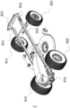
FIG. 1 is a perspective view of a riding mower according to an example of the present application; -
FIG. 2 is a perspective view of the riding mower inFIG. 1 from another perspective; -
FIG. 3 is a perspective view of a mowing assembly, a grass collecting pipe, a traveling assembly, and a frame of a riding mower according to an example of the present application; -
FIG. 4 is a top view of a three-dimensional structure inFIG. 3 ; -
FIG. 5 is a perspective view of a body and an accommodation device of a riding mower according to an example of the present application; -
FIG. 6 is a perspective view illustrating the structure of a back plate assembly of a riding mower according to an example of the present application; -
FIG. 7 is an exploded view of a deck, a grass collecting pipe, and a back plate according to an example of the present application; -
FIG. 8 is a perspective view of the back plate and a connector inFIG. 7 ; -
FIG. 9 is a perspective view illustrating the structure of a plug assembly according to an example of the present application; -
FIG. 10 is an exploded view of a detached upper cover of an accommodation device according to an example of the present application; -
FIG. 11 is a perspective view illustrating the structure of a back plate assembly and a support bracket of an accommodation device according to an example of the present application; -
FIG. 12 is a perspective view illustrating the structure of a grass collecting detection device according to an example of the present application; -
FIG. 13 is an exploded view of the grass collecting detection device inFIG. 12 ; -
FIG. 14A is a perspective view illustrating the structure of a full grass detection device in a first state; -
FIG. 14B is a perspective view illustrating the structure of a full grass detection device in a second state; -
FIG. 15 is an exploded view illustrating the structure of the full grass detection device inFIG. 14B ; -
FIG. 16 is a perspective view illustrating the structure of a control panel of the riding mower inFIG. 1 ; -
FIG. 17 is a schematic view of a display interface of the control panel inFIG. 16 ; -
FIG. 18 is a perspective view illustrating the structure of a seat, a grass collecting pipe, and a support assembly of the seat of the riding mower inFIG. 1 ; -
FIG. 19 is a perspective view illustrating the structure of the grass collecting pipe and the support assembly inFIG. 18 ; -
FIG. 20 is a perspective view illustrating the structure of the support assembly inFIG. 18 ; -
FIG. 21 is a perspective view illustrating the structure of a mowing assembly, a grass collecting pipe, and a height adjustment member inFIG. 1 ; -
FIG. 22 is a perspective view illustrating the structure of the height adjustment member and a frame inFIG. 21 ; -
FIG. 23 is a perspective view illustrating the structure of the height adjustment member inFIG. 21 ; -
FIG. 24 is a perspective view illustrating the structure of a brake mechanism, a grass collecting pipe, and a frame inFIG. 1 ; -
FIG. 25 is a perspective view illustrating the structure of the brake mechanism and the frame inFIG. 24 ; -
FIG. 26 is a perspective view illustrating the structure of the brake mechanism and the frame inFIG. 24 ; -
FIG. 27 is a perspective view illustrating the structure of a seat and a control device inFIG. 1 ; -
FIG. 28 is a perspective view illustrating the structure of the seat and the control device inFIG. 27 from another perspective; -
FIG. 29 is a perspective view illustrating the structure of a mowing assembly inFIG. 1 ; -
FIG. 30 is a control schematic diagram of a circuit system of the riding mower inFIG. 1 ; -
FIG. 31 is a control schematic diagram of a first mowing motor and a second mowing motor inFIG. 30 ; -
FIG. 32 is a side view of a riding mower according to an example of the present application; -
FIG. 33 is a perspective view of a mowing assembly, a grass collecting pipe, a traveling assembly, and a frame of a riding mower inFIG. 32 ; -
FIG. 34 is a top view of a three-dimensional structure inFIG. 33 ; -
FIG. 35 is an electrical schematic diagram between a power supply device, control circuits, traveling electric motors, and traveling wheels according to an example of the present application; and -
FIG. 36 is an exploded view of a traveling electric motor and a traveling wheel of a riding mower according to an example of the present application. - As shown in
FIG. 1 , a ridingmower 100 disclosed in the present application is a lawn tractor. A user may sit or stand on the ridingmower 100 to control the ridingmower 100 to trim lawns and other vegetation. In this specification, directions such as the front, rear, left, right, up, and down are described as directions shown inFIG. 1 . Specifically, when the user sits on the ridingmower 100 on the ground, it is defined that a direction which the user faces is the front, a direction which the user faces away from is the rear, a direction on the left-hand side of the user is the left, a direction on the right-hand side of the user is the right, a direction facing the ground is the down, and a direction away from the ground is the up. - As shown in
FIGS. 1 to 4 , the ridingmower 100 includes a mowingassembly 10, ahousing assembly 20, agrass collecting mechanism 30, apower supply device 40, an operatingassembly 50, a travelingassembly 60, aframe 91, and aseat 92. Theframe 91 extends basically along the front and rear direction. Theframe 91 and thehousing assembly 20 form a body of the ridingmower 100. The body is at least used for mounting or supporting the mowingassembly 10, theseat 92, and thepower supply device 40. Thepower supply device 40 is used for supplying energy to the mowingassembly 10, the travelingassembly 60, and the like so that the ridingmower 100 can be used as a power tool. Theelectric riding mower 100 is more environmentally friendly and more energy-efficient than a fuel-based riding mower. - Specifically, the
housing assembly 20 includes at least aleft cover 21, aright cover 22, and afront cover 23. Thefront cover 23 is disposed on the front part of the ridingmower 100 and is the front face of the ridingmower 100. Thepower supply device 40 is at least used for supplying electric power to the mowingassembly 10, the travelingassembly 60, and the like. Thepower supply device 40 includes at least one battery pack for storing electrical energy. In this example, thepower supply device 40 is disposed on the front part of the ridingmower 100 and is covered by thefront cover 23. Thepower supply device 40 includes the battery pack and a battery holder housing for mounting the battery pack. One or multiple battery packs and battery holders may be provided. In some examples, the total energy of thepower supply device 40 is greater than or equal to 0.5 kW h and less than or equal to 6 kW h. In some examples, the total energy of thepower supply device 40 is greater than or equal to 1 kW·h and less than or equal to 5 kW h. The total energy of the preceding power supply device may be understood as the sum of the energy of all battery packs. In some examples, thepower supply device 40 includes at least a first battery pack and a second battery pack. The energy of the first battery pack or the second battery pack is greater than or equal to 0.1 kW h and less than or equal to 4 kW·h. At least one battery pack pluggably connected to the riding mower to supply power to at least the traveling electric motor, The at least one battery pack is adaptable to another electrical device, and the electrical device includes a lighting device or a handheld power tool. - The traveling
assembly 60 is used for supporting theframe 91 so that the ridingmower 100 can travel on the ground. Specifically, theframe 91 includes longitudinal beams and cross beams. In some examples, theframe 91 includes a firstlongitudinal beam 911, a secondlongitudinal beam 912, afirst cross beam 913, and asecond cross beam 914. The firstlongitudinal beam 911 is disposed on the left side of theseat 92, and the secondlongitudinal beam 912 is disposed on the right side of theseat 92. The extension direction of the firstlongitudinal beam 911 is parallel to the extension direction of the secondlongitudinal beam 912. Thefirst cross beam 913 is disposed on the front side of theseat 92. Thefirst cross beam 913 is basically located at the front end of the ridingmower 100, and thesecond cross beam 914 is basically located at the rear end of the ridingmower 100. In this manner, thefirst cross beam 913 and thesecond cross beam 914 serve as bumpers to protect the front end and rear end of the ridingmower 100 from being damaged. The travelingassembly 60 includes left traveling wheels and right traveling wheels. The left traveling wheels include a front left travelingwheel 611 and a rearleft traveling wheel 612. The right traveling wheels include a frontright traveling wheel 621 and a rearright traveling wheel 622. The front left travelingwheel 611 and the frontright traveling wheel 621 are connected through afront axle 915. The rearleft traveling wheel 612 and the rearright traveling wheel 622 are connected through arear axle 916. - In some examples, as shown in
FIG. 1 , thepower supply device 40 is at least partially located in front of front traveling wheels in the front and rear direction. The preceding front traveling wheels include the front left travelingwheel 611 and the frontright traveling wheel 621. Specifically, in the front and rear direction, the distance L1 between the front side of thepower supply device 40 and thefront axle 915 is greater than or equal to 0 and less than or equal to 500 mm. In some examples, in the front and rear direction, the distance L1 between the front side of thepower supply device 40 and thefront axle 915 is greater than or equal to 0 and less than or equal to 300 mm. In some examples, in the front and rear direction, the distance L1 between the front side of thepower supply device 40 and thefront axle 915 is equal to 200 mm. - The mowing
assembly 10 is used for outputting power to implement the function of the ridingmower 100. The mowingassembly 10 serves as a power output member. In some examples, the mowingassembly 10 includes mowingelements 12, adeck 11 accommodating at least part of themowing elements 12, and mowingmotors 13 for driving themowing elements 12 to rotate. Themowing elements 12 are used for cutting vegetation when rotating at high speed. For example, themowing elements 12 are blades for cutting grass on the lawn. Thedeck 11 surrounds a mowingspace 111 for accommodating at least part of themowing elements 12. That is to say, themowing elements 12 are at least partially accommodated in thedeck 11, and the mowingmotors 13 are used for driving themowing elements 12 to rotate. The mowingassembly 10 is disposed below theframe 91. In some examples, two mowingelements 12 may be provided and two mowingmotors 13 may be provided. In some examples, three mowingelements 12 may be provided and three mowingmotors 13 may be provided. Themowing elements 12 are located in the mowingspace 111 surrounded by thedeck 11. The mowingspace 121 is open downward so that themowing elements 12 can perform cutting operations on the vegetation below the mowingspace 111. - In some examples, the mowing
assembly 10 is detachable from the ridingmower 100. In this case, a work attachment interface of the ridingmower 100 may be connected to another work attachment, such as a snow shoveling assembly. In this manner, the ridingmower 100 is no longer just a riding mower and may also be a riding vehicle that can perform different tasks according to different connected work attachments. Different work attachment interfaces are used for matching different work attachments, and the same work attachment interface may match different work attachments. - The
grass collecting mechanism 30 is used for collecting the grass clippings cut by the mowingassembly 10. As shown inFIGS. 4 to 7 , thegrass collecting mechanism 30 includes anaccommodation device 31 for accommodating grass clippings and agrass collecting pipe 32 connected to thedeck 11. Theaccommodation device 31 is detachable or movably mounted to abody 100a. Thebody 100a includes at least the mowingassembly 10, the travelingassembly 60, and thegrass collecting pipe 32. Theaccommodation device 31 is used for collecting the grass clippings cut by the mowingassembly 10, and thegrass collecting pipe 32 is used for guiding the grass clippings into theaccommodation device 31. Specifically, thegrass collecting mechanism 30 further includes aback plate assembly 33. Theback plate assembly 33 is used for supporting thegrass collecting pipe 32 and mounting theaccommodation device 31. - Specifically, the
back plate assembly 33 includes aback plate 332 disposed between theaccommodation device 31 and thegrass collecting pipe 32. Theback plate 332 is fixed to theframe 91 through fixing brackets. Specifically, the fixing brackets include afirst fixing bracket 341 and asecond fixing bracket 342. Thefirst fixing bracket 341 and thesecond fixing bracket 342 are fixedly mounted to the firstlongitudinal beam 911 and the secondlongitudinal beam 912 of theframe 91 through screw fastening, respectively. The left side and right side of theback plate 332 are fixedly mounted to thefirst fixing bracket 341 and thesecond fixing bracket 342. In some examples, theback plate 332 includes an upperback plate part 3321 and a lowerback plate part 3322. The upperback plate part 3321 is made of plastic and vent holes are distributed in the upperback plate part 3321 so that the weight of the vehicle body can be effectively reduced and the grass collecting efficiency can be improved. The lowerback plate part 3322 is made of metal so that the strength of the lower part of the back plate can be improved and the collision damage to the plastic back plate is avoided. - The
grass collecting pipe 32 extends upward and backward from the transverse middle of the rear part of thedeck 11 to form agrass outlet 321. Thegrass outlet 321 connects with theaccommodation device 31 and is used for the grass cut by the mowingelement 12 to be transferred from the mowingassembly 10 to theaccommodation device 31 through thegrass collecting pipe 32 so that the grass accumulates in theaccommodation device 31. The projection of thegrass collecting pipe 32 on afirst plane 101 supporting the travelingassembly 60 is at least partially located between the left traveling wheels and the right traveling wheels. Specifically, thegrass collecting pipe 32 extends backward between the rearleft traveling wheel 612 and the rearright traveling wheel 622, passes above therear axle 916 connecting the rearleft traveling wheel 612 to the rearright traveling wheel 622, and finally, is mounted to theback plate 332. - In some examples, the area of the
grass outlet 321 is greater than or equal to 0.03 m2 and less than or equal to 0.04 m2. Specifically, the area of thegrass outlet 321 is 0.0325 m2. In some examples, the wind speed at thegrass outlet 321 is greater than or equal to 10 m/s and less than or equal to 20 m/s. The flow rate at thegrass outlet 321 is greater than or equal to 0.325 m3/s and less than or equal to 0.65 m3/s. In some examples, the ratio of the maximum total capacity (Ah) of the power supply device to the flow rate (m3/s) at thegrass outlet 321 of the grass collecting pipe is greater than or equal to 10 and less than or equal to 450. In some examples, the ratio of the maximum total capacity of the power supply device to the flow rate at thegrass outlet 321 of the grass collecting pipe is greater than or equal to 50 and less than or equal to 150. In some examples, the ratio of the maximum total capacity of the power supply device to the flow rate at thegrass outlet 321 of the grass collecting pipe is greater than or equal to 60 and less than or equal to 120. - In some examples, as shown in
FIG. 2 , the ratio of the width W1 of thepower supply device 40 in the left and right direction to the width W2 of the ridingmower 100 in the left and right direction is greater than or equal to 0.2 and less than or equal to 1.5. In some examples, the ratio of the width W1 of thepower supply device 40 in the left and right direction to the width W2 of the ridingmower 100 in the left and right direction is greater than or equal to 0.2 and less than or equal to 0.8. In some examples, the ratio of the width W1 of thepower supply device 40 in the left and right direction to the width W2 of the ridingmower 100 in the left and right direction is greater than or equal to 0.3 and less than or equal to 0.5. - In some examples, the traveling
assembly 60 further includes a travelingelectric motor 63 for driving the travelingassembly 60 to travel and atransmission device 64. Since thegrass collecting mechanism 30 of the ridingmower 100 in the present application is disposed substantially in the middle, the travelingelectric motor 63 and thetransmission device 64 need to be reasonably arranged. In this example, thetransmission device 64 is mounted to therear axle 916, the travelingelectric motor 63 drives thetransmission device 64 to rotate, thetransmission device 64 drives therear axle 916 to rotate, and therear axle 916 drives the rearleft traveling wheel 612 and the rearright traveling wheel 622 to rotate, thereby driving theriding mower 100 to travel on the ground. In some examples, the travelingelectric motor 63 is located below thegrass collecting pipe 32 in the up and down direction. In some examples, the travelingelectric motor 63 is disposed behind therear axle 916 in the front and rear direction. In some examples, the projection of the travelingelectric motor 63 on thefirst plane 101 supporting the travelingassembly 60 at least partially overlaps the projection of thegrass collecting pipe 32 on thefirst plane 101. In some examples, the travelingelectric motor 63 is not lower than theback plate assembly 33 in the up and down direction, thereby protecting the travelingelectric motor 63 from being hit. - In some examples, the
grass collecting pipe 32 includes afirst pipe part 322 connected to thedeck 11 and asecond pipe part 323 connecting with thefirst pipe part 322. The front end of thesecond pipe part 323 connects with the rear end of thefirst pipe part 322. In some examples, thefirst pipe part 322 is detachably connected to thedeck 11. In some examples, thefirst pipe part 322 is integrally formed with thedeck 11. - The
grass collecting pipe 32 includes afirst end 324 connected to thedeck 11 and asecond end 325 opposite to thefirst end 324. Thefirst end 324 of thegrass collecting pipe 32 connects with the mowingspace 111 formed by thedeck 11, and thesecond end 325 is mounted to theback plate assembly 33. In some examples, thesecond end 325 of thegrass collecting pipe 32 is mounted to theback plate 332 throughmounts 331. Themount 331 has a first state in which themount 331 prevents thegrass collecting pipe 32 from being separated from theback plate assembly 33 and a second state in which thegrass collecting pipe 32 is allowed to be separated from theback plate assembly 33. When themount 331 is in the first state, themount 331 is connected to theback plate assembly 33. When themount 331 is in the second state, themount 331 is connected to theback plate assembly 33. When themount 331 is switched from the first state to the second state in which thegrass collecting pipe 32 is allowed to be separated from theback plate assembly 33, themount 331 is still connected to theback plate assembly 33. In other words, themount 331 is always connected to theback plate assembly 33, thereby preventing themount 331 from being lost. - Specifically, as shown in
FIGS. 7 and8 , themount 331 includes alocking rod 3311 and a limitingportion 3312. The lockingrod 3311 is rotatably mounted on the upperback plate part 3321. The limitingportion 3312 is fixedly formed on or connected to the upperback plate part 3321. Thesecond end 325 of thegrass collecting pipe 32 is formed with or connected to a connectingportion 326. Specifically, when the user needs to mount thegrass collecting pipe 32 to theback plate assembly 33, the user needs to operate the lockingrods 3311 along the directions of the arrow a1 and the arrow a2 inFIG. 8 to move the lockingrods 3311 to the limitingportions 3312 so that themounts 331 are in the first state, thereby relatively locking thegrass collecting pipe 32 on theback plate assembly 33. When the user needs to disassemble thegrass collecting pipe 32 from theback plate assembly 33, the user needs to operate the lockingrods 3311 along the directions of the arrow b1 and the arrow b2 inFIG. 8 to move the lockingrods 3311 away from the limitingportions 3312 so that themounts 331 are in the second state, thereby separating thegrass collecting pipe 32 from theback plate assembly 33. The preceding relative locking means that in this state, thesecond end 325 of thegrass collecting pipe 32 is adaptively rotatable about afirst axis 102. The connectingportion 326 extends substantially along the precedingfirst axis 102. In this manner, during the grass collecting process of the ridingmower 100, when the user adjusts the height of the mowingassembly 10, thesecond end 325 of thegrass collecting pipe 32 is adaptively rotatable about thefirst axis 102 to match the position change of thefirst end 324 of thegrass collecting pipe 32. In addition, themounts 331 are detachably fixedly mounted on theback plate assembly 33 and are not easy to loosen or be lost. - As shown in
FIG. 9 , the ridingmower 100 further includes aplug assembly 37. After theplug assembly 37 is mounted to thegrass collecting pipe 32, the ridingmower 100 enters a grass shredding mode. Specifically, theplug assembly 37 includes aplug 371, ahandle 372, and anextension rod 373 connecting theplug 371 to thehandle 372. Theplug 371 can be disposed near thefirst end 324 of thegrass collecting pipe 32 to isolate thedeck 11 from thegrass collecting pipe 32. The length of theextension rod 373 is basically the same as the length of thegrass collecting pipe 32, and the extension direction of theextension rod 373 is similar to the extension direction of thegrass collecting pipe 32. Thehandle 372 is used for the user to hold. When the user mounts theplug assembly 37, theplug assembly 37 is inserted into thegrass outlet 321 and pushed to thesecond end 325 of thegrass collecting pipe 32. After theplug assembly 37 is mounted, thehandle 372 is substantially located at thegrass outlet 321. In some examples, the ridingmower 100 further includes a plug detection device for detecting whether theplug 371 is located at an installation position, thereby improving the safety performance of the ridingmower 100. Of course, those skilled in the art can reasonably design the sensors and the arrangement positions of the sensors of the plug detection device according to actual application conditions. For this, no limitation is made in the present application. - The
accommodation device 31 is used for collecting the grass clippings cut by the mowingassembly 10. As shown inFIGS. 5 ,10 , and11 , theaccommodation device 31 includes asupport bracket 311 and anupper cover 314 covering thesupport bracket 311. In some examples, adecorative cover 3142 is disposed on theupper cover 314 so that thedecorative cover 3142 is used for the user to open to view the state of the grass clippings in theaccommodation device 31 while beautifying the appearance. In some examples, abent portion 3141 is formed on or connected to a side of theupper cover 314. Thebent portion 3141 is used for connecting amiddle cover 24. In this manner, theaccommodation device 31 is easy to install and has relatively strong waterproof and grass-proof performance. - The
accommodation device 31 further includesmounts 312 connected to thesupport bracket 311, where themounts 312 are hung on theback plate assembly 33. Further, themounts 312 are formed with or connected to ahandle 313 for the user to carry. Thehandle 313 is disposed above theupper cover 314. In this example, themounts 312 are made of metal. To improve the user's feel and the appearance, thehandle 313 is further wrapped with a plastic part. - The
grass collecting mechanism 30 further includessupport members 35 for supporting theaccommodation device 31 hung on theback plate assembly 33. Specifically, thesupport members 35 are connected to fixingbrackets 34 and extend backward through theback plate 332 to formsupport portions 351 for supporting theaccommodation device 31. Thesupport portions 351 are used for supporting themounts 312 of theaccommodation device 31, thereby implementing the function of supporting theaccommodation device 31. Thesupport portion 351 is formed with or connected to aguide portion 352 for guiding theaccommodation device 31 during installation so that it is convenient for the user to mount theaccommodation device 31 to theback plate assembly 33 more quickly. In this example, twosupport members 35 are provided, and abalance rod 353 extending substantially along the left and right direction is further disposed between the twosupport members 35. Thebalance rod 353 is used for improving the strength of thesupport members 35, preventing thesupport members 35 from tilting, and improving the assembly accuracy. - The
accommodation device 31 is connected to theback plate assembly 33 in a hanging manner so that it is convenient for the user to mount or disassemble theaccommodation device 31. To improve the stability of the accommodation device, in some examples, as shown inFIGS. 6 and11 , alocking device 36 is disposed between theback plate 332 and the lower front edge of theaccommodation device 31 and is used for connecting and fixing the lower part of theaccommodation device 31 to theback plate 36. The lockingdevice 36 includes anengagement part 361 fixed on theback plate 36 and a pushingpart 362 applying the engagement force and the retaining force to theengagement part 361. Specifically, theengagement part 361 is set in a hook shape and is hooked to thesupport bracket 311 of theaccommodation device 31. The pushingpart 362 is configured to be a spring. - In some examples, as shown in
FIGS. 5 ,12, and 13 , theaccommodation device 31 has a grass collecting position, and the ridingmower 100 further includes a grasscollecting detection device 334 for detecting whether theaccommodation device 31 is located at the grass collecting position. The grasscollecting detection device 334 is disposed on theback plate assembly 33. In some examples, the grass collectingdetection device 334 is disposed on the upper left or upper right of the upperback plate part 3321. Specifically, the grass collectingdetection device 334 includes at least one non-contact switch. When theaccommodation device 31 is mounted at the grass collecting position, theaccommodation device 31 triggers the grass collectingdetection device 334. Specifically, the grass collectingdetection device 334 includes anelastic piece 3341, afirst swingarm 3342, asecond swingarm 3343, amounting box 3344, and aHall switch 3345. Themounting box 3344 is mounted to the front side of the upperback plate part 3321, and thesecond swingarm 3343 and theHall switch 3345 are disposed in themounting box 3344. Theelastic piece 3341 is mounted to the rear side of the upperback plate part 3321. One end of thefirst swingarm 3342 is rotatably connected to themounting box 3344, and the other end of thefirst swingarm 3342 extends through the upperback plate part 3321 to the rear end of theelastic piece 3341. Amagnet 3345a of theHall switch 3345 is mounted on thesecond swingarm 3343, and asensor 3345b of theHall switch 3345 is mounted on the inner wall of themounting box 3344. Thefirst swingarm 3342 is drivingly connected to thesecond swingarm 3343. In some examples, thefirst swingarm 3342 and thesecond swingarm 3343 are connected by splines. In some examples, the grass collectingdetection device 334 further includes aspring 3346 disposed in themounting box 3344. One end of thespring 3346 abuts against the inner wall of themounting box 3344, and the other end of thespring 3346 abuts against thesecond swingarm 3343. - The working principle of the grass collecting
detection device 334 is as follows: when theaccommodation device 31 is mounted at the installation position, theaccommodation device 31 presses theelastic piece 3341, theelastic piece 3341 drives thefirst swingarm 3342 to rotate relative to themounting box 3344, thefirst swingarm 3342 drives thesecond swingarm 3343 to rotate synchronously, and thesecond swingarm 3343 compresses thespring 3346 and drives themagnet 3345a to approach thesensor 3345b, thereby triggering theHall switch 3345. In this manner, the grass collectingdetection device 334 is provided so that the safety performance of the ridingmower 100 can be improved, and the user can be prevented from activating the mowing function when theaccommodation device 31 is not mounted. When theaccommodation device 31 is removed from the installation position, thesecond swingarm 3343 rotates in the opposite direction under the action of thespring 3346 to drive themagnet 3345a of theHall switch 3345 away from thesensor 3345b, theHall sensor 3345 enters an untriggered state from a triggered state, the rotatingsecond swingarm 3343 drives thefirst swingarm 3342 to rotate synchronously, and thesecond swingarm 3343 drives theelastic piece 3341 to return to the original position. - The
mounting box 3344 of the grass collectingdetection device 334 in this example adopts a closed design so that themounting box 3344 is waterproof and dustproof and has relatively high safety performance. In some examples, thefirst swingarm 3342 is designed in an arc hook shape so that the opening of the upperback plate part 3321 can be narrowed and the risk of thefirst swingarm 3342 getting stuck caused by the accumulation of grass clippings can be avoided. In addition, the ridingmower 100 may experience bumps during traveling. To reduce the impact of theaccommodation device 31 on the grass collectingdetection device 334 during bumps, since the Hall witch needs to have a certain stroke before the Hall switch can be triggered, in this example, the function of the grass collectingdetection device 334 is implemented by using the Hall switch. Of course, those skilled in the art can also use other forms of detection devices to detect whether theaccommodation device 31 is mounted. - During the working process of the riding
mower 100, when the height of the grass clippings in theaccommodation device 31 affects the grass intake at a grass inlet, the user needs to dump the grass clippings. In the traditional riding mower, whether the grass clippings in theaccommodation device 31 need to be dumped is generally determined based on the experience of the user, and the timing is often too early or too late. To accurately determine the dumping time of the accommodation device, multiple checks are required, affecting the working efficiency. - Further, the riding
mower 100 in the present application has the function of automatically reminding the user that theaccommodation device 31 is full of grass. It is to be understood that when the grass clippings in theaccommodation device 31 reach such an amount that the grass clippings need to be dumped, the user can know the case without getting out of the vehicle. As shown inFIG. 5 andFIGS. 14A to 15 , the ridingmower 100 further includes a fullgrass detection device 335 for detecting the state of the grass clippings in theaccommodation device 31. The fullgrass detection device 335 is disposed on theback plate assembly 33 and located below thegrass outlet 321. - Specifically, the full
grass detection device 335 includes amounting box 3351, afirst swingarm 3352, asecond swingarm 3353, atelescopic rod 3354, and aswitch 3355. Themounting box 3351 is fixedly mounted to the lowerback plate part 3322 and is disposed on the front side of the lowerback plate part 3322. Thesecond swingarm 3353 and theswitch 3355 are disposed in themounting box 3351. One end of thefirst swingarm 3352 is rotatably connected to themounting box 3351, and the other end of thefirst swingarm 3352 extends through the lowerback plate part 3322 into theaccommodation device 31. In this example, theswitch 3355 is a Hall switch, amagnet 3355a is mounted on thesecond swingarm 3353, and asensor 3355b is mounted on the inner wall of themounting box 3351. Thefirst swingarm 3352 is drivingly connected to thesecond swingarm 3353. In some examples, thefirst swingarm 3352 and thesecond swingarm 3353 are connected by splines. In some examples, the fullgrass detection device 335 further includes aspring 3356 disposed in themounting box 3351. One end of thespring 3356 abuts against the inner wall of themounting box 3351, and the other end of thespring 3356 abuts against thesecond swingarm 3353. Of course, theswitch 3355 may adopt different switch forms and may have different positions, and those skilled in the art should arrange theswitch 3355 according to actual situations. - The working principle of the full
grass detection device 335 is as follows: when the grass clippings enter theaccommodation device 31 from thegrass outlet 321, the grass clippings accumulate upward from the bottom of theaccommodation device 31 and gradually press on thefirst swingarm 3352; and when the grass clippings pressing on thefirst swingarm 3352 reach a certain weight, thefirst swingarm 3352 rotates downward relative to themounting box 3351, thefirst swingarm 3352 drives thesecond swingarm 3353 to rotate synchronously, and thesecond swingarm 3353 compresses thespring 3356 and drives themagnet 3355a to approach thesensor 3355b, thereby triggering theswitch 3355. In this manner, the fullgrass detection device 335 is configured to automatically detect the state of the grass clippings in the accommodation device so that the user can accurately determine the time when it is necessary to clean theaccommodation device 31 without looking at theaccommodation device 31. When the grass clippings in theaccommodation device 31 are cleaned or theaccommodation device 31 is removed, the force applied to thefirst swingarm 3352 becomes smaller or disappears, thesecond swingarm 3353 rotates in the opposite direction under the action of thespring 3356 to drive themagnet 3355a of theswitch 3355 away from thesensor 3355b, theswitch 3355 enters the untriggered state from the triggered state, and the rotatingsecond swingarm 3353 drives thefirst swingarm 3352 to rotate synchronously to return to the original position. - Of course, the user may adjust the length of the part of the
telescopic rod 3354 inserted into thefirst swingarm 3352 according to the type of grass, the mowing height, and the conditions of dry grass or wet grass so that it is ensured that when a grass discharge signal is sent, the accommodation device is basically full of grass, thegrass outlet 321 is not blocked by grass clippings, and grass can be discharged normally during mowing. - In some examples, the full
grass detection device 335 further includes thetelescopic rod 3354. Thefirst swingarm 3352 is sleeved on thetelescopic rod 3354. Specifically, thetelescopic rod 3354 has a first state shown inFIG. 14A and a second state shown inFIG. 14B . It is to be understood that the grass collecting rate in theaccommodation device 31 when thetelescopic rod 3354 is in the first state and the fullgrass detection device 335 outputs the full grass signal is different from the grass collecting rate in theaccommodation device 31 when thetelescopic rod 3354 is in the second state and the fullgrass detection device 335 outputs the full grass signal. For example, when the lawn where the ridingmower 100 is working is dry or the grass is relatively dry, the user adjusts thetelescopic rod 3354 to the first state shown inFIG. 14A . When the lawn where the ridingmower 100 is working is relatively wet, the user may adjust thetelescopic rod 3354 to the second state shown inFIG. 14B . In this manner, thetelescopic rod 3354 is provided on thefirst swingarm 3352 so that the state of the fullgrass detection device 335 can be adaptively adjusted according to the working conditions, and it is convenient for the user to adjust the grass collecting rate when the full grass reminder occurs. - In this example, the
mounting box 3351 adopts a closed design and is waterproof and dustproof. Circles of multiple drainage holes are provided at the bottom of themounting box 3351 so that mud and sand on the wheels can be effectively prevented from splashing into themounting box 3351. - As shown in
FIGS. 1 and2 , the operatingassembly 50 of the ridingmower 100 includes acontrol panel 51, a steering wheel assembly, and a pedal assembly. The pedal assembly includes anaccelerator pedal 531 and abrake pedal 532. Thecontrol panel 51 and the steering wheel assembly are disposed between theseat 92 and thefront cover 23. In this example, the steering wheel assembly includes asteering wheel 521 operable by the user to control the traveling direction of the ridingmower 100. Thecontrol panel 51 is connected to thefront cover 23 and includes adisplay device 511 and multiple operatingmembers 512. Thedisplay device 511 is used for displaying the state information of the ridingmower 100. Themultiple operating members 512 are operable by the user to control the travelingassembly 60 and the mowingassembly 10. Themultiple operating members 512 may include switches, buttons, gears, or the like. Themultiple operating members 512 may be configured in different shapes and sizes so that the user can operatedifferent operating members 512 without looking at the operatingmembers 512. - Specifically, as shown in
FIGS. 16 and17 , thedisplay device 511 has adisplay interface 513 for displaying the working state of the ridingmower 100. Thedisplay interface 513 is understood as a display region directly observed by the user. Different state information may be displayed on thedisplay interface 513 as needed. Thedisplay interface 513 may display the traveling speed of the travelingassembly 60, the rotational speed of themowing elements 12, the energy efficiency state of the ridingmower 100, the remaining power information of thepower supply device 40, warning information, fault information, the remaining operation time, and the like. - In this example, the
display interface 513 is further configured to display at least the state of thegrass collecting mechanism 30. The state of thegrass collecting mechanism 30 includes afull grass state 5131, agrass basket state 5132, plug installation 5133, or a grass collecting pipe installation instruction 5234. In addition, thedisplay interface 513 is further configured to display the operation information of the travelingelectric motor 63 or information about thepower supply device 40 for supplying power to theriding mower 100. - In some examples, the
control panel 51 further includes multiple buttons arranged around thedisplay interface 513, for example, afirst button 514 and asecond button 515 used for the user to operate to adjust the maximum traveling speed and the rotational speed of the blades of the ridingmower 100, respectively. Thefirst button 514 and thesecond button 515 may be separately disposed on the left and right sides of thedisplay interface 513. Further, athird button 516 is provided around thedisplay interface 513 and is used for the user to operate to control the lighting function of the ridingmower 100. Further, afourth button 517 is provided around thedisplay interface 513. Thefourth button 517 is operable by the user so that the ridingmower 100 enters different driving modes, such as a sport mode, a normal mode, and a control mode. In this manner, the user may select different driving modes according to personal preferences, thereby improving the user experience of the ridingmower 100. Thefirst button 514, thesecond button 515, thethird button 516, and the fourth button 517may all be displayed on thedisplay interface 513 accordingly. - In some examples, as shown in
FIGS. 18 to 20 , theseat 92 is located above thegrass collecting pipe 32 in the up and down direction. Theseat 92 is mounted to asupport assembly 92a and supported by thesupport assembly 92a. Thesupport assembly 92a includes afirst support member 921 and asecond support member 922 connected to the firstlongitudinal beam 911 and the secondlongitudinal beam 912, respectively. Specifically, afirst end 921a of thefirst support member 921 is fixed to the left side of theseat 92 and fixed to the fixingbracket 34 on the firstlongitudinal beam 911. Afirst end 922a of thesecond support member 922 is fixed to the right side of theseat 92 and fixed to the fixingbracket 34 on the secondlongitudinal beam 912. To ensure the relative positions of the left and right support members and improve the overall support strength of the seat, in this example, thesupport assembly 92a further includes aconnector 923 disposed between thefirst support member 921 and thesecond support member 922. Theconnector 923 is located between theseat 92 and thegrass collecting pipe 32 in the up and down direction. Specifically, afirst end 923a of theconnector 923 is connected to thefirst end 921a of thefirst support member 921, and asecond end 923b of theconnector 923 is connected to thesecond end 922a of thesecond support member 922. In some examples, theconnector 923 is a sheet metal part, has relatively high strength, and can better support theseat 92. Of course, thefirst support member 921, thesecond support member 922, and theconnector 923 may also be integrally formed. - In some examples, as shown in
FIGS. 21 to 23 , the ridingmower 100 further includes aheight adjustment member 14 for adjusting the height of thedeck 11. In other words, the user operates theheight adjustment member 14 to control the height of themowing elements 12 to achieve different cutting effects. - Specifically, the
height adjustment member 14 includes a firstheight adjustment assembly 141, a secondheight adjustment assembly 142, a height adjustment operating assembly 143 for driving the firstheight adjustment assembly 141 or the secondheight adjustment assembly 142, and asecond connection assembly 144 disposed between the firstheight adjustment assembly 141 and the secondheight adjustment assembly 142. The firstheight adjustment assembly 141 is fixedly connected to the left side of thedeck 11, and the secondheight adjustment assembly 142 is fixedly connected to the right side of thedeck 11. One end of thesecond connection assembly 144 is fixedly connected to the firstheight adjustment assembly 141, and the other end of thesecond connection assembly 144 is fixedly connected to the secondheight adjustment assembly 142. The deck adjustment process of the ridingmower 100 is as follows: the user operates the height adjustment operating assembly 143 to drive the secondheight adjustment assembly 142 to move to adjust the right side of thedeck 11 to move in the up and down direction, the moving secondheight adjustment assembly 142 drives thesecond connection assembly 144 to move, and thesecond connection assembly 144 drives the firstheight adjustment assembly 141 to drive the left side of thedeck 11 to move in the up and down direction. - The
second connection assembly 144 includes afirst part 144a, asecond part 144b, and athird part 144c. Thefirst part 144a is connected to the firstheight adjustment assembly 141, thesecond part 144b is connected to the secondheight adjustment assembly 142, one end of thethird part 144c is connected to thefirst part 144a, and the other end of thethird part 144c is connected to thesecond part 144b. The firstheight adjustment assembly 141 drives thefirst part 144a to move, thefirst part 144a drives thethird part 144c to move, and thethird part 144c drives thesecond part 144b to move, thereby driving the secondheight adjustment assembly 142 to move. Specifically, thethird part 144c is at least partially disposed on the upper part of thegrass collecting pipe 32. In some examples, thethird part 144c is configured to be a sheet metal part. - In some examples, the
height adjustment member 14 further includes an elastic assembly for reducing the operating force of the user operating the heightadjustment operating assembly 143, thereby improving the user experience. Specifically, the elastic assembly includes a spring 1451 and aswingarm 1452. Theswingarm 1452 is mounted to thefirst part 144a or thesecond part 144b of thesecond connection assembly 144. One end of the spring 1451 is mounted to theswingarm 1452, and the other end of the spring 1451 is mounted to the fixingbracket 34. In this manner, when the user operates the heightadjustment operating member 143, the heightadjustment operating member 143 tends to move to a preset position under the force of the spring 1451, which not only helps the user save effort but also provides a better operating feel. - In some examples, as shown in
FIGS. 24 to 26 , the ridingmower 100 further includes abrake mechanism 70 for braking the travelingassembly 60 during traveling. Thebrake mechanism 70 includes afirst brake assembly 71 for braking the rearleft traveling wheel 612 and asecond brake assembly 72 for braking the rearright traveling wheel 622. Thebrake mechanism 70 further includes a brake operating assembly 73 operable by the user for driving thefirst brake assembly 71 or thesecond brake assembly 72. - Specifically, the
brake operating assembly 73 includes abrake pedal 731 and adrive rod 732. Thedrive rod 732 is disposed between thebrake pedal 731 and thefirst brake assembly 71 and is used for transmitting a braking force on thebrake pedal 731 to thefirst brake assembly 71. Thebrake mechanism 70 further includes afirst connection assembly 74 connecting thefirst brake assembly 71 to thesecond brake assembly 72. Thefirst connection assembly 74 includes aconnector 741 located on the upper side or the lower side of thegrass collecting pipe 32. The braking process of the ridingmower 100 is as follows: the user depresses thebrake pedal 731 forward to drive thedrive rod 732 to move forward, thedrive rod 732 drives thefirst brake assembly 71 to brake the rearleft traveling wheel 612, thefirst brake assembly 71 drives, through thefirst connection assembly 74, thesecond brake assembly 72 to move synchronously during the braking process, and thesecond brake assembly 72 brakes the rearright traveling wheel 622. - In some examples, the
first connection assembly 74 further includes areinforcement part 742 connected to two ends of theconnector 741. Thereinforcement part 742 and theconnector 741 form abracket 74a, and thegrass collecting pipe 32 is located in thebracket 74a. Specifically, thereinforcement part 742 includes afirst part 742a, asecond part 742b, and athird part 742c. Thefirst part 742a is connected to thefirst brake assembly 71, thethird part 742c is connected to thesecond brake assembly 72, and thesecond part 742b connects thefirst part 742a to thethird part 742c. To improve the force transmission efficiency on two sides of thefirst connection assembly 74 and ensure the consistency of braking on two sides, thereinforcement part 742 is set in a "U" shape and is an integrally formed sheet metal part. - In some examples, as shown in
FIGS. 2 ,27 , and28 , the ridingmower 100 further includes acontrol device 80 for controlling the operation state. Thecontrol device 80 includes ahousing 81 and acircuit board assembly 82 disposed in thehousing 81. Specifically, thecontrol device 80 is mounted on theframe 91 and is located between a front traveling assembly and a rear traveling assembly. Thecontrol device 80 is at least partially located on the front side of theseat 92. In some examples, the distance L2 between the upper end of thecontrol device 80 and the seat surface of theseat 92 is greater than or equal to 0 and less than or equal to 800 mm. In some examples, the distance L2 between the upper end of thecontrol device 80 and the seat surface of theseat 92 is greater than or equal to 100 mm and less than or equal to 400 mm. In some examples, the distance L2 between the upper end of thecontrol device 80 and the seat surface of theseat 92 is greater than or equal to 200 mm and less than or equal to 300 mm. The upper end of the precedingcontrol device 80 should be understood as the highest point of thehousing 81. The seat surface of the preceding seat should be understood as the lowest point of the seat surface. - In some examples, the
control device 80 is inclined relative to thefirst plane 101 supporting the travelingassembly 60. Specifically, thecircuit board assembly 82 is inclined relative to thefirst plane 101 supporting the travelingassembly 60. Thecircuit board assembly 82 includes a driver circuit for driving the traveling electric motor. The driver circuit is disposed on a printedcircuit board 821, and the printed circuit board is inclined relative to thefirst plane 101. In some examples, the included angle α between the plane where the printedcircuit board 821 is located and thefirst plane 101 is greater than or equal to 0° and less than or equal to 85°. In some examples, the included angle α between the plane where the printedcircuit board 821 is located and thefirst plane 101 is greater than or equal to 10° and less than or equal to 30°. In some examples, the included angle α between the plane where the printedcircuit board 821 is located and thefirst plane 101 is greater than or equal to 30° and less than or equal to 50°. In some examples, the included angle α between the plane where the printedcircuit board 821 is located and thefirst plane 101 is greater than 50° and less than or equal to 70°. In some examples, the included angle α between the plane where the printedcircuit board 821 is located and thefirst plane 101 is greater than or equal to 70° and less than or equal to 85°. In some examples, the included angle α between the plane where the printedcircuit board 821 is located and thefirst plane 101 is equal to 23°. In this manner, thecontrol device 80 is inclined so that thecontrol device 80 can be prevented from interfering with thegrass collecting pipe 32, and at the same time, without increasing the length of the ridingmower 100, more space is reserved for the user, making the structure of the whole machine more compact. Of course, in some examples, thecontrol device 80 may be placed horizontally. The preceding horizontal placement may be understood as follows: the extension direction of thehousing 81 is basically parallel to thefirst plane 101, or the extension direction of the printedcircuit board 821 is basically parallel to thefirst plane 101. - The
grass collecting pipe 32 of the ridingmower 100 is set at the middle position, so the mowingassembly 10 not only needs to rotate at high speed to cut the grass during operation, but also needs to generate a backward airflow in the mowingspace 111 of thedeck 11 to bring the cut grass clippings into thegrass collecting pipe 32 from the rear part of thedeck 11, and finally, the grass is stored in theaccommodation device 31. In some examples, as shown inFIGS. 4 and29 , themowing elements 12 include afirst mowing element 121 and asecond mowing element 122. The mowingmotors 13 include afirst mowing motor 131 and asecond mowing motor 132. Thefirst mowing motor 131 drives thefirst mowing element 121, and thesecond mowing motor 132 drives thesecond mowing element 122. Specifically, thefirst mowing element 121 and thesecond mowing element 122 are adjacent to each other, and one of thefirst mowing element 121 and thesecond mowing element 122 is disposed obliquely in front of the other one of thefirst mowing element 121 and thesecond mowing element 122. - In some examples, the
first mowing element 121 rotates clockwise inFIG. 29 and thesecond mowing element 122 rotates counterclockwise so that a combined airflow directed from front to back is generated in the region P closest to the rotation paths of thefirst mowing element 121 and thesecond mowing element 122 in thedeck 11, thereby discharging the cut grass clippings into thegrass collecting pipe 32 together with the combined airflow. In other words, the directions of rotation and the rotational speeds of thefirst mowing element 121 and thesecond mowing element 122 are set so that the cut grass clippings flow to theaccommodation device 31 through thegrass collecting pipe 32. Of course, it is also feasible that thefirst mowing element 121 is configured to rotate counterclockwise and thesecond mowing element 122 is configured to rotate clockwise. In some examples, it is also feasible that thefirst mowing element 121 and thesecond mowing element 122 are configured to rotate counterclockwise or clockwise at different rotational speeds or the same rotational speed at the same time. In this manner, the efficiency of grass clippings entering thegrass collecting pipe 32 can be improved just by setting the states of thefirst mowing element 121 and thesecond mowing element 122, thereby improving the grass collecting efficiency. - As shown in
FIG. 30 , the riding mower further includes a circuit system. The circuit system includes a controller 83, adisplay circuit board 84, asignal circuit board 85, a traveling driver circuit 86, and a mowing driver circuit 87. Further, the controller 83 includes a travelingcontroller 831 and amowing controller 832. The travelingcontroller 831 is electrically connected to the traveling driver circuit 86 to output a traveling control signal to the traveling driver circuit 86 to control the state of the travelingelectric motor 63. The mowingcontroller 832 is electrically connected to the mowing driver circuit 87 to output a mowing control signal to the mowing driver circuit 87 to control the state of the mowingmotors 13. The controller 83 is further electrically connected to thesignal circuit board 85 to receive switching signals from the operating members and buttons on thecontrol panel 51. The controller 83 is electrically connected to thedisplay circuit board 84 through thesignal circuit board 85 to control the display state on thedisplay interface 513. The controller 83 is further connected to the grass collectingdetection device 334, the fullgrass detection device 335, and aplug detection device 371 so that the state of theaccommodation device 31 and the state of theplug assembly 37 are displayed on thedisplay device 511 through thedisplay circuit board 84. - In some examples, as shown in
FIG. 31 , the mowingcontroller 832 includes afirst mowing controller 8321 and asecond mowing controller 8322. The mowing driver circuit 87 includes a firstmowing driver circuit 871 and a secondmowing driver circuit 872. Thefirst mowing controller 8321 is electrically connected to the firstmowing driver circuit 871 to control the state of thefirst mowing motor 131. Thesecond mowing controller 8322 is electrically connected to the secondmowing driver circuit 872 to control the state of thesecond mowing motor 132. Specifically, thefirst mowing controller 8321 is electrically connected to the firstmowing driver circuit 871 to output a first mowing control signal to the firstmowing driver circuit 871 to drive thefirst mowing element 121 to rotate. Thesecond mowing controller 8322 is electrically connected to the secondmowing driver circuit 872 to output a second mowing control signal to the secondmowing driver circuit 872 to drive thesecond mowing element 122 to rotate. The first mowing control signal is different from the second mowing control signal. - As shown in
FIGS. 32 to 36 , the ridingmower 100 includes the mowingassembly 10, thehousing assembly 20, thegrass collecting mechanism 30, thepower supply device 40, the operatingassembly 50, the travelingassembly 60, theframe 91, and theseat 92. Theframe 91 extends basically along the front and rear direction. Theframe 91 and thehousing assembly 20 form the body of the ridingmower 100. The body is at least used for mounting or supporting the mowingassembly 10, theseat 92, and thepower supply device 40. Thepower supply device 40 is used for supplying energy to the mowingassembly 10, the travelingassembly 60, and the like so that the ridingmower 100 can be used as a power tool. Theelectric riding mower 100 is more environmentally friendly and more energy-efficient than a fuel-based riding mower. - Specifically, the
power supply device 40 is at least partially disposed on the front part of the ridingmower 100. Specifically, thepower supply device 40 is located at least partially in front of theseat 92 in the front and rear direction. Thepower supply device 40 includes the battery pack and the battery holder housing for mounting the battery pack. The battery pack is detachably mounted in the battery holder housing. One or multiple battery packs and battery holders may be provided. In some examples, the total energy of thepower supply device 40 is greater than or equal to 0.5 kW h and less than or equal to 6 kW h. In some examples, the total energy of thepower supply device 40 is greater than or equal to 1 kW·h and less than or equal to 5 kW·h. The total energy of the preceding power supply device may be understood as the sum of the energy of all battery packs. The travelingassembly 60 is used for supporting theframe 91 so that the ridingmower 100 can travel on the ground. Specifically, theframe 91 includes longitudinal beams and cross beams. In some examples, theframe 91 includes the firstlongitudinal beam 911, the secondlongitudinal beam 912, thefirst cross beam 913, and thesecond cross beam 914. The firstlongitudinal beam 911 is disposed on the left side of theseat 92, and the secondlongitudinal beam 912 is disposed on the right side of theseat 92. The extension direction of the firstlongitudinal beam 911 is parallel to the extension direction of the secondlongitudinal beam 912. Thefirst cross beam 913 is disposed on the front side of theseat 92. Thefirst cross beam 913 is basically located at the front end of the ridingmower 100, and thesecond cross beam 914 is basically located at the rear end of the ridingmower 100. In this manner, thefirst cross beam 913 and thesecond cross beam 914 serve as bumpers to protect the front end and rear end of the ridingmower 100 from being damaged. The travelingassembly 60 includes left traveling wheels and right traveling wheels. The left traveling wheels include the front left travelingwheel 611 and the rearleft traveling wheel 612. The right traveling wheels include the frontright traveling wheel 621 and the rearright traveling wheel 622. - The mowing
assembly 10 is used for outputting power to implement the function of the ridingmower 100. The mowingassembly 10 serves as a power output member. In some examples, the mowingassembly 10 includes the mowing elements (not shown in the figure), thedeck 11 accommodating at least part of the mowing elements, and the mowing motors for driving the mowing elements to rotate. In some examples, the mowingassembly 10 is detachable from the ridingmower 100. In this case, a work attachment interface of the ridingmower 100 may be connected to another work attachment, such as a snow shoveling assembly. In this manner, the ridingmower 100 is no longer just a riding mower and may also be a riding vehicle that can perform different tasks according to different connected work attachments. Different work attachment interfaces are used for matching different work attachments, and the same work attachment interface may match different work attachments. - The
grass collecting mechanism 30 is used for collecting the grass clippings cut by the mowingassembly 10. Thegrass collecting mechanism 30 includes theaccommodation device 31 for accommodating grass clippings and thegrass collecting pipe 32 connected to thedeck 11. Theaccommodation device 31 is detachable or movably mounted to theriding mower 100. Theaccommodation device 31 is used for collecting the grass clippings cut by the mowingassembly 10, and thegrass collecting pipe 32 is used for guiding the grass clippings into theaccommodation device 31. Thegrass collecting pipe 32 extends upward and backward from the transverse middle of the rear part of thedeck 11 to form thegrass outlet 321. Thegrass outlet 321 connects with theaccommodation device 31 and is used for the grass cut by the mowing element to be transferred from the mowingassembly 10 to theaccommodation device 31 through thegrass collecting pipe 32 so that the grass accumulates in theaccommodation device 31. The projection of thegrass collecting pipe 32 on thefirst plane 101 supporting the travelingassembly 60 is at least partially located between the left traveling wheels and the right traveling wheels. Specifically, thegrass collecting pipe 32 extends backward between the rearleft traveling wheel 612 and the rearright traveling wheel 622. - The traveling
assembly 60 further includes traveling electric motors for driving the traveling wheels to travel. Since thegrass collecting mechanism 30 of the ridingmower 100 in the present application is disposed substantially in the middle, the installation position of the traveling electric motor needs to be reasonably set. In some examples, the traveling electric motor is at least partially disposed inside the traveling wheel. In some examples, the projection of the rotor of the traveling electric motor on thefirst plane 101 is basically located within the projection of the traveling wheel on thefirst plane 101. Specifically, the traveling electric motors include a first travelingelectric motor 631 and a second travelingelectric motor 632. The first travelingelectric motor 631 is used for driving the rearleft traveling wheel 612, and the second travelingelectric motor 632 is used for driving the rearright traveling wheel 622. The ridingmower 100 further includes acontrol circuit 70 that is electrically connected to thepower supply device 40 and used for controlling the operation of the first travelingelectric motor 631 and the second travelingelectric motor 632. In some examples, thecontrol circuit 70 includes afirst control circuit 71 electrically connected to the first travelingelectric motor 631 and asecond control circuit 72 electrically connected to the second travelingelectric motor 632. Of course, in some examples, the first travelingelectric motor 631 and the second travelingelectric motor 632 may also be controlled by the same control circuit. - In some examples, the projection of the first traveling
electric motor 631 or the second travelingelectric motor 632 on thefirst plane 101 does not overlap the projection of thegrass collecting pipe 32 on thefirst plane 101. Of course, in some examples, the first travelingelectric motor 631 and the second travelingelectric motor 632 are used for driving the rearleft traveling wheel 612 and the rearright traveling wheel 622, respectively. Specifically, the first travelingelectric motor 631 is built into the tire of the rearleft traveling wheel 612 and is used for driving the rearleft traveling wheel 612 to rotate about the rotation axis relative to the body so that the ridingmower 100 moves relative to the ground. The first travelingelectric motor 631 is mounted to the rearleft traveling wheel 612 and then fixed through a fixingmember 611a. The second travelingelectric motor 632 is built into the tire of the rearright traveling wheel 622 and is used for driving the rearright traveling wheel 622 to rotate about the rotation axis relative to the body so that the ridingmower 100 moves relative to the ground. The second travelingelectric motor 632 is mounted to the rearright traveling wheel 622 and then fixed through a fixing member. In this example, the traveling electric motor for driving the traveling wheel to rotate is a wheel hub motor. The wheel hub motor may directly drive the traveling wheel to rotate or may be connected to a deceleration device to drive the traveling wheel to rotate. Of course, in some examples, the traveling electric motor may be a wheel motor at least partially disposed in the traveling wheel. The advantage of using the wheel hub motor or the wheel motor is that the electric motor is integrated into the traveling wheel so that a wider installation position can be reserved for the grass collecting pipe, and wider installation positions can be reserved for other components, such as a seat height adjustment assembly, the brake assemblies, and a cutting deck height adjustment assembly. On the other hand, the electric motor is disposed in the traveling wheel so that while the space is effectively saved, the electric motor can be protected from being hit by obstacles on the ground. - In some examples, the first traveling
electric motor 631 and the second travelingelectric motor 632 are used for driving the front left travelingwheel 611 and the frontright traveling wheel 621, respectively. Of course, in some examples, four traveling electric motors may be provided and used for separately driving the four traveling wheels of the riding mower. - In some examples, the total rated power of the traveling electric motors is greater than or equal to 100 W and less than or equal to 1000 W, such as 300 W, 400 W, 500 W, 600 W, or 1000 W. In some examples, the rotational speed of the wheel hub motor is less than or equal to 400 RPM. In some examples, the rotational speed of the wheel hub motor is greater than or equal to 30 RPM and less than or equal to 120 RPM. In some examples, the rotational speed of the wheel hub motor is greater than or equal to 50 RPM and less than or equal to 100 RPM. In some examples, the torque of the wheel hub motor is less than or equal to 35 N.m. Optionally, the torque of the wheel hub motor is greater than or equal to 10 N·m and less than or equal to 25 N·m.
- In some examples, the diameter D1 of the rear
left traveling wheel 612 is greater than or equal to 16 inches and less than or equal to 22 inches. For example, the diameter D1 of the rearleft traveling wheel 612 may be 20 inches. In some examples, the tire width L of the rearleft traveling wheel 612 is greater than or equal to 6 inches and less than or equal to 10 inches. For example, the tire width L of the rearleft traveling wheel 612 may be 7 inches or 8 inches. In some examples, the hub diameter D2 of the rearleft traveling wheel 612 is greater than or equal to 6 inches and less than or equal to 10 inches. For example, the hub diameter D2 of the rearleft traveling wheel 612 may be 8 inches. In an example, the traveling speed of the rearleft traveling wheel 612 is less than or equal to 2 m/s. Optionally, the traveling speed of the rearleft traveling wheel 612 is greater than or equal to 0.4 m/s and less than or equal to 1.4 m/s, such as 0.4 m/s, 0.7 m/s, 0.9 m/s, 1.3 m/s, or 1.4 m/s. It is to be noted that the specific parameters of the rearright traveling wheel 622 are configured to be the same as those of the rearleft traveling wheel 612.
Claims (15)
- A riding mower (100), comprising:a mowing assembly (10) comprising a mowing element (12) and a deck (11) accommodating at least part of the mowing element;a traveling assembly (60) comprising left traveling wheels (612) and right traveling wheels (622);a traveling electric motor (63) for driving the traveling assembly;a grass collecting pipe (32) connected to the deck to guide grass clippings; anda power supply device (40) configured to supply power to the traveling electric motor;wherein a projection of the grass collecting pipe on a first plane (101) supporting the traveling assembly is at least partially located between the left traveling wheels and the right traveling wheels, and maximum total energy of the power supply device is greater than or equal to 0.5 kW h and less than or equal to 6 kW h.
- The riding mower of claim 1, wherein the power supply device is at least partially located in front of front traveling wheels in a front and rear direction.
- The riding mower of claim 2, wherein the front traveling wheels are connected through a front axle (915); and in the front and rear direction, a distance L1 between a front side of the power supply device and the front axle is greater than or equal to 0 and less than or equal to 500 mm.
- The riding mower of claim 1, wherein a ratio of a width W1 of the power supply device in a left and right direction to a width W2 of the riding mower in the left and right direction is greater than or equal to 0.2 and less than or equal to 1.5.
- The riding mower of claim 1, wherein the power supply device comprises at least one battery pack pluggably connected to the riding mower to supply power to at least the traveling electric motor.
- The riding mower of claim 5, wherein the at least one battery pack is adaptable to another electrical device, and the electrical device comprises a lighting device or a handheld power tool.
- The riding mower of claim 1, further comprising a frame (91) and a back plate assembly (33), wherein the mowing assembly and the traveling assembly are mounted to the frame, the back plate assembly comprises a fixing bracket (341) and a back plate (332) mounted on the fixing brackets, and the fixing bracket is mounted to the frame.
- The riding mower of claim 7, wherein the grass collecting pipe comprises a first end (324) connected to the deck and a second end (325) opposite to the first end, and the second end is rotatably connected to the back plate.
- The riding mower of claim 7, further comprising a full grass detection device (335) for detecting a state of the grass clippings in an accommodation device (31), wherein the full grass detection device is mounted to the back plate and comprises a non-contact switch.
- The riding mower of claim 7, wherein the mowing assembly further comprises a first mowing motor (131) for driving a first mowing element (121) and a second mowing motor (132) for driving a second mowing element (122), and a direction of rotation of the first mowing motor is opposite to a direction of rotation of the second mowing motor.
- The riding mower of claim 1, further comprising a brake mechanism (70), wherein the brake mechanism comprises a first brake assembly (71) for braking a front left traveling wheel (611) and a second brake assembly (72) for braking a front right traveling wheel (621), the brake mechanism further comprises a first connection assembly (74) connecting the first brake assembly to the second brake assembly, and the first connection assembly comprises a first connector (741) located on an upper side or a lower side of the grass collecting pipe.
- The riding mower of claim 1, further comprising a height adjustment member (14), wherein the height adjustment member comprises a first height adjustment assembly (141), a second height adjustment assembly (142), and a second connection assembly (144) for connecting the first height adjustment assembly to the second height adjustment assembly, wherein the first height adjustment assembly and the second height adjustment assembly are connected to the deck, and at least part of the second connection assembly is located above the grass collecting pipe.
- The riding mower of claim 1, further comprising a seat (92) supported by a first support member (921) and a second support member (922), wherein a connector (923) is disposed between the first support member and the second support member, and at least part of the connector is located above the grass collecting pipe.
- The riding mower of claim 1, wherein the power supply device comprises a first battery pack and a second battery pack, and maximum energy of the first battery pack or the second battery pack is greater than or equal to 0.1 kW h and less than or equal to 4 kW h.
- The riding mower of claim 1, wherein a projection of the traveling electric motor on the first plane supporting the traveling assembly at least partially overlaps the projection of the grass collecting pipe on the first plane.
Applications Claiming Priority (8)
| Application Number | Priority Date | Filing Date | Title |
|---|---|---|---|
| CN202223594505.4U CN219205267U (en) | 2022-12-30 | 2022-12-30 | Riding mower |
| CN202223594503.5U CN219205266U (en) | 2022-12-30 | 2022-12-30 | Riding mower |
| CN202211726334.8A CN118266322A (en) | 2022-12-30 | 2022-12-30 | Riding mower |
| CN202223594528.5U CN219205268U (en) | 2022-12-30 | 2022-12-30 | Riding mower |
| CN202223594606.1U CN219205269U (en) | 2022-12-30 | 2022-12-30 | Riding mower |
| CN202223594401.3U CN219205265U (en) | 2022-12-30 | 2022-12-30 | Riding mower |
| CN202223611276.2U CN218998888U (en) | 2022-12-30 | 2022-12-30 | Riding mower |
| CN202320439347.0U CN219844077U (en) | 2023-03-09 | 2023-03-09 | Riding mower |
Publications (2)
| Publication Number | Publication Date |
|---|---|
| EP4393290A2 true EP4393290A2 (en) | 2024-07-03 |
| EP4393290A3 EP4393290A3 (en) | 2024-09-04 |
Family
ID=88779146
Family Applications (1)
| Application Number | Title | Priority Date | Filing Date |
|---|---|---|---|
| EP23208944.1A Pending EP4393290A3 (en) | 2022-12-30 | 2023-11-10 | Riding mower |
Country Status (2)
| Country | Link |
|---|---|
| US (1) | US20240215490A1 (en) |
| EP (1) | EP4393290A3 (en) |
Family Cites Families (10)
| Publication number | Priority date | Publication date | Assignee | Title |
|---|---|---|---|---|
| JP3776071B2 (en) * | 2002-09-26 | 2006-05-17 | 株式会社クボタ | Grass collecting device and mower equipped with the grass collecting device |
| EP1985487B1 (en) * | 2007-04-24 | 2018-08-08 | Kanzaki Kokyukoki Mfg. Co., Ltd. | Riding lawn mower |
| WO2018031719A1 (en) * | 2016-08-10 | 2018-02-15 | Briggs & Stratton Corporation | User-scalable power unit including removable battery packs |
| WO2020025024A1 (en) * | 2018-08-01 | 2020-02-06 | 南京德朔实业有限公司 | Riding lawn mower, and current-limiting protection method for same |
| JP7199960B2 (en) * | 2018-12-26 | 2023-01-06 | 株式会社クボタ | electric lawn mower |
| US20220190426A1 (en) * | 2019-03-28 | 2022-06-16 | Briggs & Stratton Corporation | Modular battery assembly for battery powered equipment |
| CN210226236U (en) * | 2019-07-19 | 2020-04-03 | 扬州维邦园林机械有限公司 | Electric mowing vehicle |
| CN214314691U (en) * | 2021-01-18 | 2021-09-28 | 宁波大叶园林设备股份有限公司 | Riding type mower |
| CN218998877U (en) * | 2021-06-25 | 2023-05-12 | 南京泉峰科技有限公司 | Riding mower |
| CN115486256A (en) * | 2022-09-29 | 2022-12-20 | 浙江亚特电器股份有限公司 | Riding type mower |
-
2023
- 2023-10-31 US US18/498,920 patent/US20240215490A1/en active Pending
- 2023-11-10 EP EP23208944.1A patent/EP4393290A3/en active Pending
Also Published As
| Publication number | Publication date |
|---|---|
| EP4393290A3 (en) | 2024-09-04 |
| US20240215490A1 (en) | 2024-07-04 |
Similar Documents
| Publication | Publication Date | Title |
|---|---|---|
| EP2731560B1 (en) | Battery powered lawn care vehicle with efficient drive controller | |
| EP3406127B1 (en) | Grass mower | |
| JP7195066B2 (en) | electric work vehicle | |
| CN115119604B (en) | Mower | |
| EP4044790A1 (en) | Electric stand-on mower with counter rotating blades | |
| CN115067059B (en) | Mower | |
| EP4393290A2 (en) | Riding mower | |
| CN219205268U (en) | Riding mower | |
| CN219205267U (en) | Riding mower | |
| CN219205265U (en) | Riding mower | |
| CN218998888U (en) | Riding mower | |
| CN219205269U (en) | Riding mower | |
| CN219205266U (en) | Riding mower | |
| CN219165151U (en) | Riding mower | |
| CN115067063B (en) | Mower | |
| CN115067064B (en) | Mower | |
| CN116114474A (en) | Riding type mowing equipment | |
| CN118266322A (en) | Riding mower | |
| CN218892647U (en) | Saddle-riding type vehicle | |
| CN218680092U (en) | Mowing tractor | |
| WO2023082770A1 (en) | Ride-on lawn mowing apparatus | |
| CN218634775U (en) | Mowing tractor | |
| CN219844077U (en) | Riding mower | |
| WO2023109646A1 (en) | Ride-on mowing device | |
| CN116114457A (en) | Mowing tractor |
Legal Events
| Date | Code | Title | Description |
|---|---|---|---|
| PUAI | Public reference made under article 153(3) epc to a published international application that has entered the european phase |
Free format text: ORIGINAL CODE: 0009012 |
|
| STAA | Information on the status of an ep patent application or granted ep patent |
Free format text: STATUS: THE APPLICATION HAS BEEN PUBLISHED |
|
| AK | Designated contracting states |
Kind code of ref document: A2 Designated state(s): AL AT BE BG CH CY CZ DE DK EE ES FI FR GB GR HR HU IE IS IT LI LT LU LV MC ME MK MT NL NO PL PT RO RS SE SI SK SM TR |
|
| PUAL | Search report despatched |
Free format text: ORIGINAL CODE: 0009013 |
|
| AK | Designated contracting states |
Kind code of ref document: A3 Designated state(s): AL AT BE BG CH CY CZ DE DK EE ES FI FR GB GR HR HU IE IS IT LI LT LU LV MC ME MK MT NL NO PL PT RO RS SE SI SK SM TR |
|
| RIC1 | Information provided on ipc code assigned before grant |
Ipc: A01D 69/10 20060101ALI20240731BHEP Ipc: A01D 67/00 20060101ALI20240731BHEP Ipc: A01D 34/66 20060101ALI20240731BHEP Ipc: A01D 69/02 20060101ALI20240731BHEP Ipc: A01D 43/063 20060101ALI20240731BHEP Ipc: A01D 34/71 20060101AFI20240731BHEP |