EP4393284A1 - Work machine - Google Patents
Work machine Download PDFInfo
- Publication number
- EP4393284A1 EP4393284A1 EP22861359.2A EP22861359A EP4393284A1 EP 4393284 A1 EP4393284 A1 EP 4393284A1 EP 22861359 A EP22861359 A EP 22861359A EP 4393284 A1 EP4393284 A1 EP 4393284A1
- Authority
- EP
- European Patent Office
- Prior art keywords
- work
- working
- route
- lines
- travelable
- Prior art date
- Legal status (The legal status is an assumption and is not a legal conclusion. Google has not performed a legal analysis and makes no representation as to the accuracy of the status listed.)
- Pending
Links
Images














Classifications
-
- A—HUMAN NECESSITIES
- A01—AGRICULTURE; FORESTRY; ANIMAL HUSBANDRY; HUNTING; TRAPPING; FISHING
- A01B—SOIL WORKING IN AGRICULTURE OR FORESTRY; PARTS, DETAILS, OR ACCESSORIES OF AGRICULTURAL MACHINES OR IMPLEMENTS, IN GENERAL
- A01B69/00—Steering of agricultural machines or implements; Guiding agricultural machines or implements on a desired track
- A01B69/007—Steering or guiding of agricultural vehicles, e.g. steering of the tractor to keep the plough in the furrow
-
- A—HUMAN NECESSITIES
- A01—AGRICULTURE; FORESTRY; ANIMAL HUSBANDRY; HUNTING; TRAPPING; FISHING
- A01B—SOIL WORKING IN AGRICULTURE OR FORESTRY; PARTS, DETAILS, OR ACCESSORIES OF AGRICULTURAL MACHINES OR IMPLEMENTS, IN GENERAL
- A01B69/00—Steering of agricultural machines or implements; Guiding agricultural machines or implements on a desired track
- A01B69/007—Steering or guiding of agricultural vehicles, e.g. steering of the tractor to keep the plough in the furrow
- A01B69/008—Steering or guiding of agricultural vehicles, e.g. steering of the tractor to keep the plough in the furrow automatic
-
- A—HUMAN NECESSITIES
- A01—AGRICULTURE; FORESTRY; ANIMAL HUSBANDRY; HUNTING; TRAPPING; FISHING
- A01B—SOIL WORKING IN AGRICULTURE OR FORESTRY; PARTS, DETAILS, OR ACCESSORIES OF AGRICULTURAL MACHINES OR IMPLEMENTS, IN GENERAL
- A01B79/00—Methods for working soil
- A01B79/005—Precision agriculture
Definitions
- a working vehicle assistance system of Patent Literature 1 includes a vehicle position detector that detects a position of a working vehicle, an unfinished region external shape map calculator that calculates an external shape map of an unfinished region within a planned work region from vehicle position data that is acquired by the vehicle position detector when the working vehicle travels along an outer periphery of the planned work region while doing work, and a path calculator that calculates a target travelling path along which the working vehicle travels while doing work in the unfinished region based on the external shape map calculated by the unfinished region external shape map calculator.
- Patent Literature 1 the external shape map of the unfinished region is calculated, and the target travelling path is created in the calculated external shape map.
- a desirable target traveling path cannot be created. For example, a traveling device of a traveling vehicle enters the non-travelable line.
- the portions of the traveling device may include a first traveling unit provided on the vehicle body and a second traveling unit provided on the vehicle body at a distance from the first traveling unit such that, in a case that the first traveling unit is located on one of the plurality of travelable lines, the second traveling unit is located on another of the plurality of travelable lines.
- the setter may extract two travelable lines from the plurality of travelable lines and set corresponding first portions based on the extracted two travelable lines.
- the first acquirer may acquire, as the plurality of non-travelable lines, a plurality of work lines which are arranged at the first interval or intervals and in which work has been done from the one of the opposite edges to the other of the agricultural field or from the other of the opposite edges to the one of the opposite edges of the agricultural field.
- the working machine may further include a route acquirer to acquire a second route along which work has been done by the vehicle body in the agricultural field, a second working device attachable to the vehicle body to do second work before first work done by the first working device, and a linkage to connect the first working device or the second working device to the vehicle body.
- the second working device may be operable to do work at the first interval or intervals.
- the route acquirer may acquire, as the second route, a plurality of second portions traveled by the vehicle body having the second working device connected thereto and extending from the one of the opposite edges to the other of the agricultural field.
- the plurality of non-travelable lines may be a plurality of work lines which are arranged at the first interval or intervals and which result from the vehicle body traveling along the plurality of second portions and the second working device doing the second work from the one of the opposite edges to the other of the agricultural field or from the other of the opposite edges to the one of the opposite edges of the agricultural field.
- the setter may set the plurality of first portions by shifting the second route acquired by the route acquirer based on the plurality of travelable lines defined by the line definer.
- the working machine may further include a position detector to detect a position of the vehicle body, and a display to display the position of the vehicle body detected by the position detector and the first route created by the route creator.
- the working machine may further include a position detector to detect a position of the vehicle body, and an auto-steering controller to control steering of the traveling device based on the position of the vehicle body detected by the position detector and the first route created by the route creator.
- the working machine may further include a position detector to detect a position of the vehicle body, and an automatic travel controller to control steering and a vehicle speed of the traveling device based on the position of the vehicle body detected by the position detector and the first route created by the route creator.
- a direction leftward of the operator is a leftward direction (a direction indicated by arrow A3 in FIG. 23 )
- a direction rightward of the operator is a rightward direction (a direction indicated by arrow A4 in FIG. 23 ).
- a horizontal direction orthogonal to a front-rear direction of the working machine 1 is a width direction.
- the front wheels 4A are connected by an arm (knuckle arm) 5 that changes a direction of the front wheels 4A.
- the knuckle arm 5 changes the direction of the front wheels 4A, thereby allowing the vehicle body 2 to travel straight and turn. Note that it is only necessary that the vehicle body 2 can travel straight and turn.
- a rotational speed of the front wheel 4A and the rear wheel 4B on the one side (left side) and a rotational speed of the front wheel 4A and the rear wheel 4B on the other side (right side) may be changed to achieve the straight traveling and turning.
- the front wheels 4A and the rear wheels 4B may be tires or may be crawlers.
- the vehicle body 2 is provided with a PTO shaft 6 that outputs power of the prime mover 8 to an outside and the operator's seat 7 on which the operator sits.
- the first creator 57d1 creates, on the field F, a plurality of unit work sections E where work is done by the working device 60 by dividing the agricultural field G on the field F into sections of the working width W vertically or horizontally, as illustrated in FIG. 6 .
- the first creator 57d1 creates, on the field F, a plurality of unit work sections E where work is done by the working device 60 by dividing the agricultural field G on the field F into sections of the working width W vertically or horizontally. That is, the first creator 57d1 creates a plurality of unit work sections E having a width identical to the working width W on the field F.
- Each of the unit work sections E extends from one of opposite edges to the other of the agricultural field G (in a first direction B1). Note that in the following description, a direction orthogonal to the first direction B 1 is sometimes referred to as a second direction B2.
- the first acquirer 57h acquires data of the work lines R1 indicated by positions (latitude and longitude) and/or data of the work lines R1 indicated by a coordinate (an X axis and a Y axis) system based on the second portion(s) La2 acquired by the route acquirer 57g and the number c2 of second working units 61a2, the unit working width Wc, the first interval x, and the second portion La2 acquired by the second work acquirer 57f.
- the setter 157b (route creator 57d) shifts the plurality of second portions La2 by about a natural number multiple of 1/2 of the difference between the first working width Wa acquired by the first work acquirer 57e and the second working width Wb acquired by the second work acquirer 57f.
- the shift amount calculated based on the expression (2) is a negative number
- the setter 157b shifts the plurality of second portions La2 rightward in the drawing by the shift amount.
- the setter 157b extracts the travelable lines R2 that reduce the unfinished region E1 and the overlapping work region E2 so that the unfinished region E1 and the overlapping work region E2 would not be generated and thus sets the first portions La1 based on the working width W included in the first information acquired by the first work acquirer 57e.
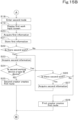
- the following describes acquisition of the second information by the second work acquirer 57f, acquisition of the first information by the first work acquirer 57e, and the like in the first mode and the second mode in accordance with a flow mainly with reference to FIGS. 15A and 15B .
- the route creator 57d enters the first mode (S3).
- the display controller 57 After the route creator 57d enters the first mode (S3), the display controller 57 causes a second work input screen D3 to be displayed on the display unit 56 (S4).
- the second work input screen D3 is a screen to receive input of information of the second working device 60B and includes a first input portion 110 to receive input of the second information.
- the first input portion 110 includes a first region 111 to receive input of the second working width Wb, a second region 112 to receive input of the number c2 of second working units 61a2, a third region 113 to receive input of the type of second working device 60B, a fourth region 114 to receive input of individual information of the second working device 60B, a fifth region 115 to receive input of the model name of the second working device 60B, a sixth region 116 to receive input of the unit working width Wc of the second working unit 61a2, and a seventh region 117 to receive input of the first interval x of the second working device 60B.
- the first region 111, the second region 112, the sixth region 116, and the seventh region 117 receive input of numerical values, for example, by an operation of the display 55.
- the third region 113, the fourth region 114, and the fifth region 115 receive input of text, for example, by an operation of the display 55.
- the second work input screen D3 may receive input of the model of the working device 60, and the second work acquirer 57f may acquire the second information from a table stored in advance in the display storing unit 58.
- the second information is stored as a table including the model of the working device 60, and the second information is acquired using the model of the working device 60 as individual information.
- the second work acquirer 57f may acquire the second information including the second working width Wb and the number c2 of second working units 61a2 based on an image taken by an imager provided in or on the working machine 1 and/or information detected by a detector such as a sensor.
- the second work acquirer 57f acquires the second information including the second working width Wb and the number c2 of second working units 61a2 input to the second work input screen D3 (S5).
- the second work acquirer 57f acquires the second information (S5)
- the acquired second information is stored in the display storing unit 58 (S6).
- the first creator 57d1 route creator 57d
- the display storing unit 58 stores the second route L2 therein (S8).
- the first work input screen D4 is a screen to receive input of information of the first working device 60A and includes a second input portion 120 to receive input of the first information, as illustrated in FIG. 17 .
- the second input portion 120 includes an eighth region 121 to receive input of the first working width (second interval) Wa, a ninth region 122 to receive input of the number c1 of first working units 61a1, a tenth region 123 to receive input of the type of first working device 60A, an eleventh region 124 to receive input of the individual information of the first working device 60A, a twelfth region 125 to receive input of the model name of the first working device 60A, a thirteenth region 126 to receive input of the unit working width Wc of the first working unit 61a1, and a fourteenth region 127 to receive input of the first interval x of the first working device 60A.
- the first working device 60A is the type II device 62 or the type III device 63
- no information is input in the ninth region 122
- the first work acquirer 57e does not acquire the number c1 of first working units 61a1.
- the first work acquirer 57e acquires the first information including the first working width Wa and the number c1 of first working units 61a1 based on the information input on the screen of the display unit 56
- a method of inputting the first information is not limited to the above method, and the source of acquisition is not limited to the information input on the first work input screen D4.
- the first work input screen D4 may receive input of the model of the working device 60, and the first work acquirer 57e may acquire the first information from a table stored in advance in the display storing unit 58.
- the first information is stored as a table including the model of the working device 60, and the first information is acquired using the model of the working device 60 as individual information.
- the first work acquirer 57e may acquire the first information including the first working width Wa and the number c1 of first working units 61a1 based on an image taken by an imager provided in or on the working machine 1 and/or information detected by a detector such as a sensor.
- the first work acquirer 57e acquires the first information including the first working width Wa and the number c1 of first working units 61a1 input to the first work input screen D4 (S11).
- the determiner 57i determines whether the second working device 60B corresponding to the second work Jn-1 is the type III device 63 based on the second information corresponding to the second route L2 (S13).
- the second creator 57d2 creates the first route L1 based on the first information acquired by the first work acquirer 57e, the second information acquired by the second work acquirer 57f, and the second route L2 acquired by the route acquirer 57g (S14).
- the second work acquirer 57f checks whether or not the second information of the second work Jn-2 preceding the second work Jn-1 subjected to determination by the determiner 57i in S12 is stored in the display storing unit 58 (S15). In a case where the second work acquirer 57f confirms that the second information of the second work Jn-2 preceding the second work Jn-1 subjected to determination by the determiner 57i in S 13 is stored (S15, Yes), the second work acquirer 57f acquires the second information of the second work Jn-2 from the display storing unit 58 (S16).
- the process returns to S 13 in which the determiner 57i determines whether the second working device 60B corresponding to the second work Jn-2 is the type III device 63 (S13).
- the first creator 57d1 creates the first route L1 based on the first information acquired by the first work acquirer 57e (S17).
- the display controller 57 causes the first work input screen D4 to be displayed on the display unit 56 (S19).
- the first work acquirer 57e acquires the first information including the first working width Wa and the number c1 of first working units 61a1 input to the first work input screen D4 (S20).
- the second work acquirer 57f confirms that the second information of the second work Jn-1 preceding the first work Jn for which the first information was acquired in S22 is stored (S22, Yes)
- the second work acquirer 57f acquires the second information of the second work Jn-1 from the display storing unit 58 (S23).
- the determiner 57i determines whether the second working device 60B corresponding to the second work Jn-1 is the type III device 63 (S24).
- the second creator 57d2 (route creator 57d) creates the first route L1 based on the first information acquired by the first work acquirer 57e, the second information acquired by the second work acquirer 57f, and the second route L2 acquired by the route acquirer 57g in a case where the non-travelable lines R1 are formed in the agricultural field G.
- the second work acquirer 57f checks whether or not the second information of the second work Jn-2 preceding the second work Jn-1 subjected to determination by the determiner 57i in S22 is stored in the display storing unit 58 (S26). In a case where the second work acquirer 57f confirms that the second information of the second work Jn-2 preceding the second work Jn-1 subjected to determination by the determiner 57i in S24 is stored (S26, Yes), the second work acquirer 57f acquires the second information of the second work Jn-2 from the display storing unit 58 (S27).
- the process returns to S24, in which the determiner 57i determines whether the second working device 60B corresponding to the second work Jn-2 is the type III device 63 (S24).
- the first creator 57d1 creates the first route L1 based on the first information acquired by the second acquirer 57e1 (S28).
- the display storing unit 58 stores the first route L1 therein (S29).
- the display controller 57 causes a route display screen D5 to be displayed on the display unit 56 and the second route L2 and the first route L1 stored in the display storing unit 58 to be displayed (S30).
- the display controller 57 acquires the vehicle body position VP detected by the position detector (positioning device) 50 and causes the current position of the working machine 1 to be displayed as an icon 130a on the route display portion 130 based on the vehicle body position VP.
- the third information display portion displays the first information acquired by the first work acquirer 57e or the second information acquired by the second work acquirer 57f in response to an operation of the switching button 131.
- the third information display portion displays, as the first information, information such as the first working width Wa, the number c1 of first working units 61a1, the type, individual information, and model name of the first working device 60A, the unit working width Wc of the first working unit 61a1, and/or the first interval x and displays, as the second information, information such as the second working width Wb, the number c2 of second working units 61a2, the type, individual information, and model name of the second working device 60B, the unit working width Wc of the second working unit 61a2, and/or the first interval x.
- the route creator 57d creates the first route L1 is merely an example.
- the first creator 57d1 creates the second route L2 (S7)
- the second route L2 is stored in the display storing unit 58 (S8)
- the route acquirer 57g acquires the second route L2 (S9)
- the display controller 57 causes the first work input screen D4 to be displayed on the display unit 56 (S10) in the present embodiment
- the following configuration may be used: when the second work acquirer 57f acquires the second information (S5), the display controller 57 causes the first work input screen D4 to be displayed on the display unit 56 (S10), and after the first work acquirer 57e acquires the first information (S11), the first creator 57d1 creates the second route L2 (S7).
- the second work acquirer 57f repeats steps S13, S15, and S16 or steps S24, S26, and S27 and checks whether or not the second information of the second work preceding the second work Jn-2 is stored in the display storing unit 58 (S26) until it is determined that the second working device 60B corresponding to the second information is not the type III device 63 (S13, S24, No) or until it is determined that the second information of the second work Jn-2 preceding the second work Jn-1 is not stored in the display storing unit 58 (S15, S26, Yes).
- the process may proceed to S17 from S15 or the process may proceed to S28 from S26.
- the route creator 57d may create a travel route L (third route) traveled by the working machine 1 during third work that is performed after the second work in addition to the first route L1 and the second route L2, and the number of travel routes L collectively created by the route creator 57d is not limited to two and may be three or four.
- the display 55 causes the travel route L (the second route L2 and the first route L1) created by the route creator 57d to be displayed on the display unit 56.
- the controller 40 of the working machine 1 may control the traveling device 4 based on the travel route L created by the route creator 57d.
- the auto-steering controller 40a rotates the rotary shaft of the steering motor 38 so that the working machine 1 is steered leftward.
- the auto-steering controller 40a may set the steering angle so that the angle ⁇ g of orientation of the vehicle body 2 with respect to the travel route L is zero (so that the orientation of the vehicle body 2 matches the orientation of the travel route L) in a case where the orientation of the travel route L and the orientation of the traveling direction of the working machine 1 (vehicle body 2) (the orientation of the vehicle body 2) are different, that is, in a case where the angle ⁇ g is equal to or larger than a predetermined angle, as illustrated in the lower portion of FIG. 20 .
- the auto-steering controller 40a may set a final steering angle of auto-steering based on a steering angle determined based on deviation (positional deviation) and a steering angle determined based on orientation (orientation deviation).
- Setting of the steering angle of auto-steering in the above embodiment is an example and is not restrictive.
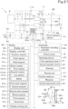
- the controller 40 includes an automatic travel controller 40b to control automatic traveling of the working machine 1, as illustrated in FIG. 21 .
- the automatic travel controller 40b includes electric/electronic circuit(s) provided in the controller 40, program(s) stored in a CPU and/or the like, and/or the like.
- the automatic travel controller 40b controls the steering motor 38 of the auto-steering mechanism 37 so that the working machine 1 travels along the travel route L.
- the automatic travel controller 40b controls the vehicle speed (traveling speed) of the working machine 1 by automatically changing speed stages of the transmission 11, the rotational speed of the prime mover 8, and the like.
- the automatic travel controller 40b controls the steering motor 38 of the auto-steering mechanism 37 so that the working machine 1 travels along the travel route L, by a method similar to the auto-steering controller 40a.
- a working machine 1 as has been described includes a vehicle body 2, a first working device 60A attachable to the vehicle body 2, a traveling device 4 on the vehicle body 2, a first acquirer 57h to acquire a plurality of non-travelable lines R1 that extend from one of opposite edges of an agricultural field G to the other and are arranged at a first interval or intervals x, and a route creator 57d to create, based on the plurality of non-travelable lines R1 acquired by the first acquirer 57h, a first route L1 including a plurality of first portions La1 to be traveled by the vehicle body 2 and extending from the one of the opposite edges to the other of the agricultural field G, wherein the traveling device 4 includes portions that are spaced apart from each other by a distance corresponding to the first interval x, and the route creator 57d includes a line definer 157a to define, as a plurality of travelable lines R2, regions of the agricultural field G other than the plurality of non-travelable lines R1 based on the plurality of non
- the working machine 1 can travel along the travelable lines R2 while avoiding the non-travelable lines R1, and therefore, in a case where the setter 157b sets the first portions La1 based on the plurality of travelable lines R2, the route creator 57d can create the first portions La1 along which the working machine 1 can travel without entering the non-travelable lines R1. This allows the working machine 1 to efficiently do work in the agricultural field G without traveling on the non-travelable lines R1.
- the portions of the traveling device 4 include a first traveling unit 4L provided on the vehicle body 2 and a second traveling unit 4R provided on the vehicle body 2 at a distance from the first traveling unit 4L such that, in a case that the first traveling unit 4L is located on one of the plurality of travelable lines R2, the second traveling unit 4R is located on another of the plurality of travelable lines R2.
- the setter 157b extracts two travelable lines R2 from the plurality of travelable lines R2 and sets corresponding first portions La1 based on the extracted two travelable lines R2. With the above configuration, the setter 157b can set the first portions La1 corresponding to the travelable lines R2 along which the first traveling unit 4L travels and the travelable lines R2 along which the second traveling unit 4R travels. The setter 157b can therefore more reliably reduce the likelihood that the first traveling unit 4L and the second traveling unit 4R will enter the non-travelable lines R1.
- the working machine 1 further includes a second acquirer 57e1 to acquire a second interval Wa which is a first working width Wa.
- the setter 157b sets the plurality of first portions La1 such that an interval between two adjacent section lines La is substantially equal to the second interval Wa based on the second interval Wa acquired by the second acquirer 57e1.
- the setter 157b can eliminate or reduce the likelihood that regions where the first working device 60A does work are separated from each other or overlap each other in a case where the working machine 1 travels along two adjacent section lines La. Therefore, the working machine 1 makes it possible to prevent or reduce the generation of the unfinished regions E1 where the first working device 60A has not done work and the overlapping work regions E2 where the first working device 60A does work twice or more.
- the first acquirer 57h acquires, as the plurality of non-travelable lines R1, a plurality of work lines R1 which are arranged at the first interval or intervals x and in which work has been done from the one of the opposite edges to the other of the agricultural field G or from the other of the opposite edges to the one of the opposite edges of the agricultural field G.
- the working machine 1 that travels along the first portions La1 can do work without entering the plurality of work lines R1. This allows the working machine 1 to do work more efficiently without damaging regions where work has been done already.
- the plurality of work lines R1 acquired as the plurality of non-travelable lines R1 by the first acquirer 57h are ridge lines Ra where ridge making has been done or crop lines Rb where crop seeds have been sown or crops have been planted.
- the working machine 1 that travels along the first portions La1 can do work without damaging the ridges or the upper surfaces of the ridges or without damaging sown seeds or grown crops. This allows the working machine 1, by traveling and doing work along the first portions La1, to efficiently do work while eliminating or reducing the likelihood that the growth of seeds and crops will be hindered or the quality of crops will be deteriorated.
- the working machine 1 further includes a route acquirer 57g to acquire a second route L2 along which work has been done by the vehicle body 2 in the agricultural field G, a second working device 60B attachable to the vehicle body 2 to do second work before first work done by the first working device 60A, and a linkage 30 to connect the first working device 60A or the second working device 60B to the vehicle body 2.
- the linkage 30 is operable to connect, to the vehicle body 2, the second working device 60B to do the second work before the first work done by the first working device 60A.
- the second working device 60B is operable to do work at the first interval or intervals x.
- the route acquirer 57g acquires, as the second route L2, a plurality of second portions La2 traveled by the vehicle body 2 having the second working device 60B connected thereto and extending from the one of the opposite edges to the other of the agricultural field G.
- the plurality of non-travelable lines R1 are a plurality of work lines R1 which are arranged at the first interval or intervals x and which result from the vehicle body 2 traveling along the plurality of second portions La2 and the second working device 60B doing the second work from the one of the opposite edges to the other of the agricultural field G or from the other of the opposite edges to the one of the opposite edges of the agricultural field G.
- the setter 157b sets the plurality of first portions La1 by shifting the second route L2 acquired by the route acquirer 57g based on the plurality of travelable lines R2 defined by the line definer 157a.
- the route creator 57d creates the first route L1 including the first portions La1 by changing the second route L2 along which the working machine 1 has done the second work, and therefore the first portions La1 can be easily set while omitting input of various kinds of information included in the second route L2. Furthermore, the work (first work) corresponding to the second work can be more appropriately done.
- the working machine 1 further includes a position detector 50 to detect a position of the vehicle body 2, and a display 55 to display the position of the vehicle body 2 detected by the position detector 50 and the first route L1 created by the route creator 57d.
- the first route L1 (first portions La1) along which the working machine 1 can travel without entering the non-travelable lines R1 can be displayed. Therefore, the operator, by visually checking the first portions La1 displayed on the display 55, operating the working machine 1 while checking the position of the vehicle body 2, and causing the working machine 1 to travel along the first portions La1 the first route L1, can efficiently do work in the agricultural field G without traveling on the non-travelable lines R1.
- the working machine further includes a position detector 50 to detect a position of the vehicle body 2, and an automatic travel controller 40b to control steering and a vehicle speed of the traveling device 4 based on the position of the vehicle body 2 detected by the position detector 50 and the first route L1 created by the route creator 57d.
- the automatic travel controller 40b causes the working machine 1 to travel along the first route L1 (first portions La1) by controlling steering and a vehicle speed without the need for the operator to steer the working machine 1 or control the vehicle speed. This allows the working machine 1 to efficiently do work in the agricultural field G without traveling on the non-travelable lines R1. It is therefore possible to further improve work performance of the working machine 1.
- the first working device 60A includes a first working unit 61a1 or a plurality of first working units 61a1 arranged at a first interval or intervals x in a width direction.
- the second working device 60B includes a second working unit 61a2 or a plurality of second working units 61a2 arranged at the first interval or intervals x in the width direction.
- the first work acquirer 57e acquires the number c1 of first working units 61a1 as the first information.
- the second work acquirer 57f acquires the number c2 of second working units 61a2 as the second information.
- the route creator 57d creates the plurality of first portions La1 by shifting the plurality of second portions La2 by a product of (i) the difference between the number c1 of first working units 61a1 acquired by the first work acquirer 57e and the number c2 of second working units 61a2 acquired by the second work acquirer 57f, (ii) the first interval x, and (iii) a natural number multiple of 1/2.
- the working machine 1 can prevent or reduce the generation of the unfinished regions E1 of the first working device 60A and the overlapping work regions E2 of the first working device 60A reliably by a simple method.
- the working machine 1 further includes a position detector 50 to detect a position of the vehicle body 2.
- the route acquirer 57g acquires the second route L2 based on one or more positions of the vehicle body 2 acquired by the position detector 50 when the vehicle body 2 having the second working device 60B connected thereto moves.
- the second route L2 can be created when the second work is done, and the working machine 1 can acquire the second route L2 easily and efficiently.
- the working machine 1 further includes a position detector 50 to detect a position of the vehicle body 2, and an automatic travel controller 40b to control steering and a vehicle speed of the traveling device 4 based on the position of the vehicle body 2 detected by the position detector 50 and the first route L1 created by the route creator 57d.
- the automatic travel controller 40b causes the working machine 1 to travel along the first route L1 (first portions La1) by controlling the steering and the vehicle speed without the need for the operator to steer the working machine 1 and control the vehicle speed. This allows the working machine 1 to efficiently do work in the agricultural field G. It is therefore possible to further improve work performance of the working machine 1.
Landscapes
- Life Sciences & Earth Sciences (AREA)
- Engineering & Computer Science (AREA)
- Mechanical Engineering (AREA)
- Soil Sciences (AREA)
- Environmental Sciences (AREA)
- Guiding Agricultural Machines (AREA)
Abstract
Description
- The present invention relates to a working machine such as a tractor.
-
Patent Literature 1 is known as a technique of creating a target travelling path for an agricultural machine. - A working vehicle assistance system of Patent Literature 1 includes a vehicle position detector that detects a position of a working vehicle, an unfinished region external shape map calculator that calculates an external shape map of an unfinished region within a planned work region from vehicle position data that is acquired by the vehicle position detector when the working vehicle travels along an outer periphery of the planned work region while doing work, and a path calculator that calculates a target travelling path along which the working vehicle travels while doing work in the unfinished region based on the external shape map calculated by the unfinished region external shape map calculator.
- PTL 1:
Japanese Unexamined Patent Application Publication No. 2017-55673 - In
Patent Literature 1, the external shape map of the unfinished region is calculated, and the target travelling path is created in the calculated external shape map. However, according to the technique disclosed inPatent Literature 1, in a case where there is a place (non-travelable line) where the working machine cannot travel due to the presence of a ridge, crops, and/or the like on an agricultural field, a desirable target traveling path cannot be created. For example, a traveling device of a traveling vehicle enters the non-travelable line. - The present invention was made to solve such an issue of the related art, and an object of the present invention is to provide a working machine that can travel along an appropriate path (travel route) irrespective of the state of an agricultural field.
- A working machine according to an aspect of the present invention includes a vehicle body, a first working device attachable to the vehicle body, a traveling device on the vehicle body, a first acquirer to acquire a plurality of non-travelable lines that extend from one of opposite edges of an agricultural field to the other and are arranged at a first interval or intervals, and a route creator to create, based on the plurality of non-travelable lines acquired by the first acquirer, a first route including a plurality of first portions to be traveled by the vehicle body and extending from the one of the opposite edges to the other of the agricultural field, wherein the traveling device includes portions that are spaced apart from each other by a distance corresponding to the first interval, and the route creator includes a line definer to define, as a plurality of travelable lines, regions of the agricultural field other than the plurality of non-travelable lines based on the plurality of non-travelable lines acquired by the first acquirer, and a setter to set, as the plurality of first portions, a path which extends from the one of the opposite edges to the other of the agricultural field and along which the traveling device travels on the plurality of travelable lines, based on the plurality of travelable lines defined by the line definer.
- The portions of the traveling device may include a first traveling unit provided on the vehicle body and a second traveling unit provided on the vehicle body at a distance from the first traveling unit such that, in a case that the first traveling unit is located on one of the plurality of travelable lines, the second traveling unit is located on another of the plurality of travelable lines. The setter may extract two travelable lines from the plurality of travelable lines and set corresponding first portions based on the extracted two travelable lines.
- The working machine may further include a second acquirer to acquire a second interval which is a working width of the first working device. The setter may set the plurality of first portions such that an interval between two adjacent straight portions is substantially equal to the second interval based on the second interval acquired by the second acquirer.
- The first acquirer may acquire, as the plurality of non-travelable lines, a plurality of work lines which are arranged at the first interval or intervals and in which work has been done from the one of the opposite edges to the other of the agricultural field or from the other of the opposite edges to the one of the opposite edges of the agricultural field.
- The plurality of work lines acquired as the plurality of non-travelable lines by the first acquirer may be ridge lines where ridge making has been done or crop lines where crop seeds have been sown or crops have been planted.
- The working machine may further include a route acquirer to acquire a second route along which work has been done by the vehicle body in the agricultural field, a second working device attachable to the vehicle body to do second work before first work done by the first working device, and a linkage to connect the first working device or the second working device to the vehicle body. The second working device may be operable to do work at the first interval or intervals. The route acquirer may acquire, as the second route, a plurality of second portions traveled by the vehicle body having the second working device connected thereto and extending from the one of the opposite edges to the other of the agricultural field. The plurality of non-travelable lines may be a plurality of work lines which are arranged at the first interval or intervals and which result from the vehicle body traveling along the plurality of second portions and the second working device doing the second work from the one of the opposite edges to the other of the agricultural field or from the other of the opposite edges to the one of the opposite edges of the agricultural field. The setter may set the plurality of first portions by shifting the second route acquired by the route acquirer based on the plurality of travelable lines defined by the line definer.
- The working machine may further include a position detector to detect a position of the vehicle body, and a display to display the position of the vehicle body detected by the position detector and the first route created by the route creator.
- The working machine may further include a position detector to detect a position of the vehicle body, and an auto-steering controller to control steering of the traveling device based on the position of the vehicle body detected by the position detector and the first route created by the route creator.
- The working machine may further include a position detector to detect a position of the vehicle body, and an automatic travel controller to control steering and a vehicle speed of the traveling device based on the position of the vehicle body detected by the position detector and the first route created by the route creator.
- According to the working machine, it is possible to travel along an appropriate path irrespective of a state of an agricultural field.
-
- [
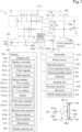
FIG. 1] FIG. 1 is a block diagram of a working machine. - [
FIG. 2] FIG. 2 illustrates a raising/lowering device. - [
FIG. 3] FIG. 3 illustrates an example of a field registration screen. - [
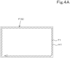
FIG. 4A] FIG. 4A is a view for finding a contour of an agricultural field from position measurement points. - [
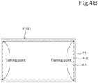
FIG. 4B] FIG. 4B is a view for finding a contour of an agricultural field from turning points. - [
FIG. 4C] FIG. 4C is a view for finding a contour of an agricultural field from corners of the agricultural field. - [
FIG. 5] FIG. 5 is a view illustrating creation of a travel route and unit work sections. - [
FIG. 6] FIG. 6 is a view for explaining the unit work sections. - [
FIG. 7] FIG. 7 illustrates a unit work section different from the unit work sections ofFIG. 6 . - [
FIG. 8A] FIG. 8A illustrates a relationship among a type I device, a work line, and a unit work section. - [
FIG. 8B] FIG. 8B illustrates a relationship among a type II device, a work line, and a unit work section. - [
FIG. 8C] FIG. 8C illustrates a relationship among a type III device, a work line, and a unit work section. - [
FIG. 9A] FIG. 9A illustrates a ridge maker as an example of the type I device. - [
FIG. 9B] FIG. 9B illustrates a seed spreader as an example of the type I device. - [
FIG. 9C] FIG. 9C illustrates an agricultural chemical spreader as an example of the type II device. - [
FIG. 9D] FIG. 9D illustrates a cultivator as an example of the type III device. - [
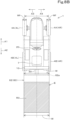
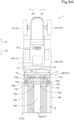
FIG. 10] FIG. 10 is a plan view illustrating a positional relationship between non-travelable lines and travelable lines and the working machine. - [
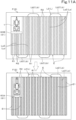
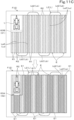
FIG. 11A] FIG. 11A is a first view for explaining a case where first work and second work are done while traveling along a second route in related art. - [
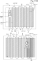
FIG. 11B] FIG. 11B is a second view for explaining a case where first work and second work are done while traveling along a second route in related art. - [
FIG. 11C] FIG. 11C is a third view for explaining a case where first work and second work are done while traveling along a second route in related art. - [
FIG. 11D] FIG. 11D is a fourth view for explaining a case where first work and second work are done while traveling along a second route in related art. - [
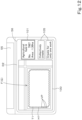
FIG. 12] FIG. 12 illustrates an example of a selection screen. - [
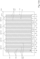
FIG. 13A] FIG. 13A is a first view for explaining the second route and the travelable lines. - [
FIG. 13B] FIG. 13B is a second view for explaining the second route and the travelable lines. - [
FIG. 14] FIG. 14 is a view for explaining setting of first portions by a setter. - [
FIG. 15A] FIG. 15A illustrates a flow of creating a first route by a route creator. - [
FIG. 15B] FIG. 15B illustrates a flow of creating a first route by a route creator. - [
FIG. 16] FIG. 16 illustrates an example of a second work input screen. - [
FIG. 17] FIG. 17 illustrates an example of a first work input screen. - [
FIG. 18] FIG. 18 illustrates an example of a route display screen. - [
FIG. 19] FIG. 19 is a block diagram of a working machine according to a first variation. - [
FIG. 20] FIG. 20 is a view for explaining auto-steering in the first variation. - [
FIG. 21] FIG. 21 is a block diagram of a working machine according to a second variation. - [
FIG. 22] FIG. 22 is a side view of the working machine. - [
FIG. 23] FIG. 23 is a front view of the working machine. - Embodiments of the present invention are described below with reference to the drawings.
-
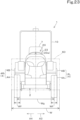
FIG. 22 is a side view illustrating an embodiment of a workingmachine 1, andFIG. 23 is a front view illustrating the embodiment of the workingmachine 1. In the present embodiment, the workingmachine 1 is a tractor equipped with a workingdevice 60. Note that the workingmachine 1 is not limited to a tractor and may be a rice planter, a combine, or the like. For convenience of description, the following discusses an example in which the workingmachine 1 is a tractor equipped with the workingdevice 60. In the following description, it is assumed that a direction (a direction indicated by arrow A1 inFIG. 22 ) forward of an operator (driver) sitting on an operator'sseat 7 of the workingmachine 1 is a forward direction, a direction (a direction indicated by arrow A2 inFIG. 22 ) rearward of the operator is a rearward direction, a direction leftward of the operator is a leftward direction (a direction indicated by arrow A3 inFIG. 23 ), and a direction rightward of the operator is a rightward direction (a direction indicated by arrow A4 inFIG. 23 ). It is also assumed that a horizontal direction orthogonal to a front-rear direction of the workingmachine 1 is a width direction. - The working
machine 1 includes avehicle body 2, aprime mover 8, a firsthydraulic pump 9, atransmission 11, and alinkage 30. As illustrated inFIG. 22 , thevehicle body 2 includes a travelingdevice 4 and can travel. The travelingdevice 4 includes at least onefront wheel 4A and at least onerear wheel 4B. Thefront wheel 4A and therear wheel 4B are arranged apart from each other in the front-rear direction. In the present embodiment, one pair offront wheels 4A are provided apart from each other in the width direction of thevehicle body 2, and one pair ofrear wheels 4B are provided apart from each other in the width direction of thevehicle body 2, as illustrated inFIG. 23 . - That is, the traveling
device 4 includes one pair offront wheels 4A and one pair ofrear wheels 4B (four wheels in total) and includes afirst traveling unit 4L (in the present embodiment, aleft front wheel 4A and a leftrear wheel 4B) provided on one side (left side) of thevehicle body 2 in the width direction and asecond traveling unit 4R (in the present embodiment, aright front wheel 4A and a rightrear wheel 4B) provided on the other side (right side) of thevehicle body 2 in the width direction apart by a predetermined interval from thefirst traveling unit 4L. Thefirst traveling unit 4L and thesecond traveling unit 4R are mounted on thevehicle body 2 apart from each other in the width direction. Note that the travelingdevice 4 may include, for example, three wheels instead of four wheels as in the present embodiment. - As illustrated in
FIG. 1 , thefront wheels 4A are connected by an arm (knuckle arm) 5 that changes a direction of thefront wheels 4A. Theknuckle arm 5 changes the direction of thefront wheels 4A, thereby allowing thevehicle body 2 to travel straight and turn. Note that it is only necessary that thevehicle body 2 can travel straight and turn. Instead of the configuration or in addition to the configuration, a rotational speed of thefront wheel 4A and therear wheel 4B on the one side (left side) and a rotational speed of thefront wheel 4A and therear wheel 4B on the other side (right side) may be changed to achieve the straight traveling and turning. Thefront wheels 4A and therear wheels 4B may be tires or may be crawlers. Thevehicle body 2 is provided with aPTO shaft 6 that outputs power of theprime mover 8 to an outside and the operator'sseat 7 on which the operator sits. - The
prime mover 8 is a diesel engine, an electric motor, or the like. In the present embodiment, theprime mover 8 is a diesel engine. Thetransmission 11 can switch propelling force of the travelingdevice 4 by changing speed stages and can switch between forward traveling and rearward traveling of the travelingdevice 4. The firsthydraulic pump 9 is provided on thevehicle body 2 and delivers hydraulic fluid. The firsthydraulic pump 9 is, for example, coupled to theprime mover 8 and delivers hydraulic fluid upon receipt of power output by theprime mover 8. - The
linkage 30 is swingably provided on thevehicle body 2 and couples the workingdevice 60. Specifically, thelinkage 30 is provided on a rear portion of thevehicle body 2. Thelinkage 30 is swingable due to firsthydraulic device 31 driven by hydraulic fluid delivered by the firsthydraulic pump 9. The workingdevice 60 is attachable and detachable to and from a rear portion of thelinkage 30. Thelinkage 30 couples the workingdevice 60, and thereby the workingdevice 60 can be towed by thevehicle body 2. - The working
device 60 is a device attachable to thevehicle body 2. In a case where the workingmachine 1 is a tractor, the workingdevice 60 is coupled to thevehicle body 2 with the use of thelinkage 30. The workingdevice 60 may operate upon receipt of power input from an outside, for example, power input from thePTO shaft 6. Alternatively, the workingdevice 60 may include hydraulic equipment (not illustrated) that is driven by hydraulic fluid delivered by the firsthydraulic pump 9, and the hydraulic equipment may cause the workingdevice 60 to operate. The workingdevice 60 is a cultivator 90 for cultivation, aridge maker 71 for ridge making, a fertilizer spreader for spreading a fertilizer, an agricultural chemical spreader 85 for spreading an agricultural chemical for pest control, aseed spreader 75 for seeding, a transplanter for transplanting a crop (seedling), a harvester for harvesting crops, a mower for mowing pasture grass or the like, a tedder for spreading pasture grass or the like, a rake for gathering pasture grass or the like, a baler for baling pasture grass or the like, or the like. That is, thelinkage 30 can couple the workingdevice 60 selected from among the various kinds described above to thevehicle body 2. - For convenience of description, the following discusses an example in which a central portion of the working
device 60 in the width direction and a central portion of the workingmachine 1 in the width direction match in the width direction as illustrated inFIG. 23 while excluding a case where the central portion of the workingdevice 60 in the width direction and the central portion of the workingmachine 1 in the width direction are deviated (offset) from each other in the width direction. However, the present invention is also applicable to the case where the central portion of the workingdevice 60 in the width direction and the central portion of the workingmachine 1 in the width direction are deviated (offset) from each other in the width direction. In this case, for example, a position of the working machine 1 (a vehicle body position VP) is changed as appropriate in processing performed by acontroller 40 and the like, which will be described later. - The
transmission 11 is described in detail below. As illustrated inFIG. 1 , thetransmission 11 includes a main shaft (propeller shaft) 11a, amain transmission unit 11b, asub-transmission unit 11c, ashuttle 11d, a PTOpower transmission unit 11e, and afront transmission unit 11f. Thepropeller shaft 11a is rotatably supported by a housing case (transmission case) of thetransmission 11. To thepropeller shaft 11a, power from a crankshaft of theprime mover 8 is transmitted. Themain transmission unit 11b includes a plurality of gears and a shifter that changes connection of the gears. Themain transmission unit 11b changes rotation input from thepropeller shaft 11a and outputs the changed rotation (change speed stages) by changing connection (engagement) of the plurality of gears as appropriate by the shifter. - Similarly, the
sub-transmission unit 11c includes a plurality of gears and a shifter that changes connection of the gears. Thesub-transmission unit 11c changes rotation input from themain transmission unit 11b and outputs the changed rotation (change speed stages) by changing connection (engagement) of the plurality of gears as appropriate by the shifter. - The
shuttle 11d includes ashuttle shaft 12 and a forward rearward travelingswitcher 13. To theshuttle shaft 12, power output from thesub-transmission unit 11c is transmitted via the gears and the like. The forward rearward travelingswitcher 13 is, for example, a hydraulic clutch or the like, and switches a rotation direction of theshuttle shaft 12, that is, switch between forward traveling and rearward traveling of the workingmachine 1 by switching the hydraulic clutch on and off. Theshuttle shaft 12 is connected to a rear wheel differential 17R. The rear wheel differential 17R rotatably supports arear axle 18R to which therear wheels 4B are attached. - The PTO
power transmission unit 11e includes aPTO propeller shaft 14 and a PTO clutch 15. ThePTO propeller shaft 14 is rotatably supported, and power from thepropeller shaft 11a can be transmitted to thePTO propeller shaft 14. ThePTO propeller shaft 14 is connected to thePTO shaft 6 via the gears and the like. The PTO clutch 15 is, for example, a hydraulic clutch or the like, and the hydraulic clutch is switched on and off to switch between a state where power of thepropeller shaft 11a is transmitted to thePTO propeller shaft 14 and a state where power of thepropeller shaft 11a is not transmitted to thePTO propeller shaft 14. - The
front transmission unit 11f includes a first clutch 16A and a second clutch 16B. To the first clutch 16A and the second clutch 16B, power from thepropeller shaft 11a can be transmitted, for example, power of theshuttle shaft 12 is transmitted via a gear and a transmission shaft. Power from the first clutch 16A and the second clutch 16B can be transmitted to afront axle 18F via afront transmission shaft 19. Specifically, thefront transmission shaft 19 is connected to a front wheel differential 17F, and the front wheel differential 17F rotatably supports thefront axle 18F to which thefront wheels 4A are attached. - The first clutch 16A and the second clutch 16B are hydraulic clutches or the like. A fluid passage is connected to the first clutch 16A, and the fluid passage is connected to a
first actuation valve 25a to which a hydraulic fluid delivered from the firsthydraulic pump 9 is supplied. The first clutch 16A is switched between a connected state and a cutoff state depending on an opening of thefirst actuation valve 25a. A fluid passage is connected to the second clutch 16B, and the fluid passage is connected to asecond actuation valve 25b. The second clutch 16B is switched between a connected state and a cutoff state depending on an opening of thesecond actuation valve 25b. Thefirst actuation valve 25a and thesecond actuation valve 25b are, for example, two-position switching valves equipped with a solenoid valve and are switched to a connected state or a cutoff state by energizing or deenergizing a solenoid of the solenoid valve. - In a case where the first clutch 16A is in a cutoff state and the second clutch 16B is in a connected state, power of the
shuttle shaft 12 is transmitted to thefront wheels 4A via the second clutch 16B. This creates a state (4WD uniform-speed state) in which thefront wheels 4A and therear wheels 4B are driven by power (four-wheel drive (4WD) and a rotational speed of thefront wheels 4A and a rotational speed of therear wheels 4B are substantially identical. On the other hand, in a case where the first clutch 16A is in a connected state and the second clutch 16B is in a cutoff state, a state (4WD increased-speed state) is created in which four-wheel drive is performed and the rotational speed of thefront wheels 4A is higher than the rotational speed of therear wheels 4B. In a case where the first clutch 16A and the second clutch 16B are in a connected state, power of theshuttle shaft 12 is not transmitted to thefront wheels 4A. This creates a two-wheel-drive (2WD) state in which therear wheels 4B are driven by power. - As illustrated in
FIG. 1 , the workingmachine 1 includes an operatingdevice 20 for operating the workingmachine 1. The operatingdevice 20 is provided around the operator'sseat 7 and can be used to operate members such as theprime mover 8, thetransmission 11, and the travelingdevice 4. The operatingdevice 20 includes, for example, afirst operation lever 21, asecond operation lever 22, and asteering 23, and the operator can hold and swing thefirst operation lever 21 and thesecond operation lever 22. Thefirst operation lever 21 is a device that can control raising/lowering of thelinkage 30, and thesecond operation lever 22 is a device that can operate the workingdevice 60 coupled to thelinkage 30. - The steering 23 is a device that allows the operator to manually steer the
vehicle body 2 so that thevehicle body 2 travels straight or turns. As illustrated inFIG. 22 , the steering 23 is provided in front of the operator'sseat 7. The steering 23 includes asteering wheel 23a and a steering shaft (rotary shaft) 23b that rotatably supports thesteering wheel 23a. The steering 23 includes an assist mechanism (power steering) 35. Theassist mechanism 35 assists rotation of thesteering shaft 23b (steering wheel 23a) by a hydraulic pressure or the like. Theassist mechanism 35 includes a secondhydraulic pump 36a, anauxiliary control valve 36b to which hydraulic fluid delivered from the secondhydraulic pump 36a is supplied, and asteering cylinder 36c actuated by theauxiliary control valve 36b. Theauxiliary control valve 36b is, for example, a three-position switching valve that can be switched by movement of a spool or the like and is switched corresponding to a steering direction (rotation direction) of thesteering shaft 23b. Thesteering cylinder 36c is connected to anarm 5 that changes a direction of thefront wheels 4A. - Therefore, when the operator holds and operates the
steering wheel 23a, a switching position and an opening of theauxiliary control valve 36b is switched depending on a rotation direction of thesteering wheel 23a, thesteering cylinder 36c extends or contracts leftward or rightward depending on the switching position and opening of theauxiliary control valve 36b, and thereby a steering direction of thefront wheels 4A can be changed. That is, thevehicle body 2 can change a traveling direction to the left or right by manual steering of thesteering wheel 23 a. - As illustrated in
FIG. 2 , thelinkage 30 includes alift arm 30a, alower link 30b, atop link 30c, and alift rod 30d. A front end portion of thelift arm 30a is supported by a rear upper portion of a case (transmission case) in which thetransmission 11 is housed so as to be swingable up or down. - A front end portion of the
lower link 30b is supported by a rear lower portion of thetransmission 11 so as to be swingable up or down. A front end portion of thetop link 30c is supported by a rear portion of thetransmission 11 above thelower link 30b so as to be swingable up or down. Thelift rod 30d couples thelift arm 30a and thelower link 30b. The workingdevice 60 is coupled to a rear portion of thelower link 30b and a rear portion of thetop link 30c. - As illustrated in
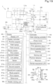
FIG. 1 , the workingmachine 1 includes acontroller 40 and a storing unit (memory and/or storage) 41. Thecontroller 40 is a device realized by an electric/electronic circuit, a program stored in a CPU or the like, and the like. Thecontroller 40 controls various devices of the workingmachine 1. Specifically, thecontroller 40 can perform control such as control of the firsthydraulic device 31, the workingdevice 60, and change of output of the firsthydraulic pump 9. The storingunit 41 is a non-volatile memory or the like and stores therein, for example, various kinds of information concerning control of thecontroller 40. - As illustrated in
FIG. 1 , the workingmachine 1 includes a position detector (positioning device) 50. Theposition detector 50 can detect a position thereof (measured position information including latitude and longitude) by a satellite positioning system (positioning satellite) such as D-GPS, GPS, GLONASS, BeiDou, Galileo, or Michibiki. That is, theposition detector 50 receives a satellite signal (a position of the positioning satellite, a transmission time, correction information, and the like) transmitted from the positioning satellite and detects a position (e.g., latitude and longitude) of the workingmachine 1, that is, a vehicle body position VP based on the satellite signal. Theposition detector 50 includes areceiver 51 and an inertial measurement unit (IMU) 52. Thereceiver 51 is a device that includes an antenna and the like and receives a satellite signal transmitted from the positioning satellite, and is attached to the workingmachine 1 separately from theinertial measurement unit 52. In the present embodiment, thereceiver 51 is attached to an upper portion of aROPS 10 provided on thevehicle body 2, as illustrated inFIGS. 22 and23 . Note that an attachment position of thereceiver 51 is not limited to the above position, and may be a central portion of a hood or, in a case where thevehicle body 2 is provided with a protection mechanism such as a cabin, may be an upper portion of the protection mechanism. - The
inertial measurement unit 52 includes an acceleration sensor that detects an acceleration, a gyroscope sensor that detects an angular speed, and the like. Theinertial measurement unit 52 is provided below the workingmachine 1, for example, below the operator'sseat 7, and can detect a roll angle, a pitch angle, a yaw angle, and the like of the workingmachine 1. - As illustrated in
FIG. 1 , the workingmachine 1 includes adisplay 55. Thedisplay 55 is, for example, a traveling assistance device provided in the vicinity of the operator'sseat 7. Thedisplay 55 includes adisplay unit 56, adisplay controller 57, and a display storing unit (memory and/or storage) 58. Thedisplay unit 56 is a liquid crystal panel, a touch panel, or another kind of panel and can display information for assisting traveling of the workingmachine 1 such as a field F expressing an agricultural field G. Thedisplay unit 56 can display various kinds of information concerning the workingmachine 1 and the workingdevice 60 in addition to the information for assisting traveling of the workingmachine 1. - The
display controller 57 is realized by an electric/electronic component provided in thedisplay 55, a program stored in thedisplay storing unit 58, which will be described later, and the like. Thedisplay controller 57 causes a screen visualizing information stored in thedisplay storing unit 58 to be displayed on thedisplay unit 56. - The
display storing unit 58 is a non-volatile memory or the like and stores therein various kinds of information concerning the workingmachine 1 and the workingdevice 60. Thedisplay 55 is communicably connected to a device provided in the workingmachine 1 by a cable or wirelessly and can transmit and receive information to and from the device. Specifically, for example, thedisplay controller 57 of thedisplay 55 and thecontroller 40 of the workingmachine 1 are communicably connected. - Note that although the
display 55 is a traveling assistance device provided in the vicinity of the operator'sseat 7 in the above embodiment, thedisplay 55 may be a computer such as a personal computer (PC), a smartphone (multifunctional mobile phone), or a tablet PC as long as thedisplay 55 includes thedisplay unit 56, thedisplay controller 57, and thedisplay storing unit 58. - As illustrated in
FIG. 1 , the workingmachine 1 includes aposition acquirer 57a, afield register 57b, and afield acquirer 57c. In the present embodiment, theposition acquirer 57a, thefield register 57b, and thefield acquirer 57c are each realized by an electric/electronic component, a program incorporated into thedisplay 55, and the like, and thedisplay controller 57 of thedisplay 55 also functions as theposition acquirer 57a, thefield register 57b, and thefield acquirer 57c. Note that although thedisplay controller 57 of thedisplay 55 also functions as theposition acquirer 57a, thefield register 57b, and thefield acquirer 57c in the present embodiment, thecontroller 40 or the like may include theposition acquirer 57a, thefield register 57b, and thefield acquirer 57c, and the configuration thereof is not limited to the above configuration. - The
position acquirer 57a acquires a plurality of position measurement points detected while the workingmachine 1 circles around the agricultural field G. Specifically, in the present embodiment, theposition acquirer 57a acquires, as a plurality of position measurement points VP, positions (vehicle body positions VP) of the workingmachine 1 detected by theposition detector 50. Note that it is only necessary that theposition acquirer 57a acquires a plurality of position measurement points, and a method for acquiring the plurality of position measurement points is not limited to the above method. It is also possible to employ a configuration in which a storing unit such as a memory in which positional information of a plurality of position measurement points is stored in advance and thedisplay 55 are connected and the positional information of the plurality of position measurement points is acquired from the storing unit. - The
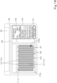
field register 57b registers a contour H1 of a predetermined agricultural field G, for example, positions corresponding to the contour H1 of the predetermined agricultural field G as the field F displayed on thedisplay unit 56. When the operator performs a predetermined operation on thedisplay 55, thedisplay controller 57 causes a field registration screen D1 to be displayed on thedisplay unit 56, as illustrated inFIG. 3 . The field registration screen D1 displays afield display portion 100 showing the field F including the agricultural field G and the vehicle body position VP of the workingmachine 1 and a firstinformation display portion 101 showing agricultural field identification information such as a name (agricultural field name) of the agricultural field G and an agricultural field management number. Not only image data of the agricultural field G, but also positional information such as latitude and longitude are associated with the field F. When the operator performs a predetermined operation on thedisplay 55, thedisplay controller 57 causes the field registration screen D1 to be displayed on thedisplay unit 56. When thedisplay unit 56 displays the field registration screen D1, the operator causes the workingmachine 1 to circle within the agricultural field G by operating the workingmachine 1. Theposition acquirer 57a acquires the vehicle body position VP detected by theposition detector 50 on a predetermined cycle, and records the vehicle body position VP in thedisplay storing unit 58 each time and causes the vehicle body position VP to be displayed on thefield display portion 100 each time (only some vehicle body positions VP are displayed inFIG. 3 for convenience of description). - When the operator selects a
registration button 102 after the workingmachine 1 finishes circling within the agricultural field G, thefield register 57b calculates a traveling track T1 of the workingmachine 1 based on the recorded vehicle body positions VP. Thedisplay controller 57 causes the traveling track T1 to be displayed on the field F in thefield display portion 100, as illustrated inFIG. 4A . In the example ofFIG. 4A , a line T1 passing the plurality of vehicle body positions VP in an order of detection (order of acquisition) and returning to an initially detected position VP is obtained as the traveling track of the workingmachine 1. - The vehicle body position VP is a GPS position of the
position detector 50, and the traveling track T1 is a track of movement of the GPS position. Accordingly, thefield register 57b forms a line H1 between the traveling track T1 and an external shape line of the field F by shifting the traveling track T1 outward by an amount equivalent to an interval in the width direction from the GPS position of the workingmachine 1 to an outer end of the circling working device 60 (inFIG. 4A , a left end of the workingdevice 60 since the workingmachine 1 circles in the agricultural field G in a clockwise direction). In the present embodiment, the shift amount is set identical to a half of an external width (a length in the width direction) of the workingdevice 60 or a half of a working width W (a length in the width direction of a range where the workingdevice 60 exerts some kind of action on the agricultural field G) of the workingdevice 60 since the GPS position of theposition detector 50 is located at a center of the workingmachine 1 and the center of the workingmachine 1 in the width direction and a center of the workingdevice 60 in the width direction match. In another example, the line H1 may be formed between the traveling track T1 and the external shape line of the field F while setting, as the shift amount, a value that is smaller by a predetermined degree or larger by a predetermined degree than the interval in the width direction from the GPS position of the workingmachine 1 to the outer end of the circling workingdevice 60. - The
field register 57b regards the line H1 thus formed as a contour (external shape) of the agricultural field G and registers (stores) the field F expressed by the contour H1 in thedisplay storing unit 58. When registering the field F in thedisplay storing unit 58, thefield register 57b associates agricultural field identification information such as a name of the agricultural field G (agricultural field name) and an agricultural field management number with the field F. A plurality of fields F and the like can be registered in thedisplay storing unit 58, and when thefield register 57b registers a field F, thedisplay controller 57 causes this field F (the contour H1 of the agricultural field G) to be displayed. - The above method for registering the agricultural field G (field F) is an example, and a method for registering the agricultural field G (field F) is not limited to this. In another example, the
field register 57b calculates turning points from the traveling track T1 of the workingmachine 1 and form a line K1 passing the turning points, as illustrated inFIG. 4B . Thefield register 57b may form a line H2 between the traveling track T1 and the external shape line of the field F by shifting the line K1 outward by the shift amount, regard the line H2 as a contour K2 of the agricultural field G and the field F, and register the field F in thedisplay storing unit 58. - Alternatively, the operator may designate corners of the agricultural field G by operating a predetermined switch or the like while the working
machine 1 circles, as illustrated inFIG. 4C . In this case, thefield register 57b forms a line K2 passing the corners of the agricultural field G in an order of designation and returning to an initially designated corners. Thefield register 57b may form a line H3 between the traveling track T1 and the external shape line of the field F by shifting the line K2 outward by the above shift amount, regard the line H3 as a contour K4 of the agricultural field G and the field F, and register the field F in thedisplay storing unit 58. - The contours H1, H2, and H3 of the agricultural field G and the field F may be, for example, data expressed by a position (latitude and longitude), data expressed by a coordinate (an X-axis and a Y-axis) system, or data expressed in another way.
- As described above, the
display 55 can register a plurality of fields F by using thefield register 57b. To do work or the like, thefield acquirer 57c acquires a field F expressing a predetermined agricultural field G among the plurality of fields F. - As illustrated in
FIG. 1 , the workingmachine 1 includes aroute creator 57d that creates a travel route L along which thevehicle body 2 travels. In the present embodiment, theroute creator 57d is realized by an electric/electronic component, a program incorporated into thedisplay 55, and the like, and thedisplay controller 57 of thedisplay 55 also functions as theroute creator 57d. Note that although thedisplay controller 57 of thedisplay 55 also functions as theroute creator 57d in the present embodiment, thecontroller 40 or the like may include theroute creator 57d, and the configuration thereof is not limited to the above configuration. - The
route creator 57d includes a first creator 57d1, and the first creator 57d1 can create the travel route L of the workingmachine 1 on the field F such as the one illustrated inFIG. 5 , for example, by referring to the field F registered in thedisplay storing unit 58. The travel route L is a route along which the workingmachine 1 travels, and the workingmachine 1 travels so that the vehicle body position VP moves along the travel route L. The first creator 57d1 creates the travel route L on the field F based on the working width W and the like. - Specifically, for example, the first creator 57d1 creates, on the field F, a plurality of unit work sections E where work is done by the working
device 60 by dividing the agricultural field G on the field F into sections of the working width W vertically or horizontally, as illustrated inFIG. 6 . The first creator 57d1 creates, on the field F, a plurality of unit work sections E where work is done by the workingdevice 60 by dividing the agricultural field G on the field F into sections of the working width W vertically or horizontally. That is, the first creator 57d1 creates a plurality of unit work sections E having a width identical to the working width W on the field F. Each of the unit work sections E extends from one of opposite edges to the other of the agricultural field G (in a first direction B1). Note that in the following description, a direction orthogonal to thefirst direction B 1 is sometimes referred to as a second direction B2. - The first creator 57d1 may create, on the field F, a plurality of unit work sections E having a width (actual working width) W2 obtained by excluding overlap(s) W1 from the working width W, as illustrated in
FIG. 7 . The overlap W1 can be input to a screen displayed on thedisplay unit 56 by operating thedisplay 55. That is, the first creator 57d1 sets, as the unit work sections E, regions where work is done on the agricultural field G by the workingdevice 60 in a case where the workingmachine 1 to which the workingdevice 60 is coupled travels. - As illustrated in
FIG. 5 , the first creator 57d1 creates, for each unit work section E of the field F, a section line La along which the workingmachine 1 travels straight. That is, for example, the first creator 57d1 creates, in a central portion of the unit work section E in the width direction, a substantially straight section line La connecting end portions of the unit work section E in a longitudinal direction. That is, the section line La extends in the first direction B1. The first creator 57d1 creates a turning portion Lb where the workingmachine 1 turns. That is, the first creator 57d1 creates the turning portion Lb by connecting end portions of adjacent section lines La in an arc manner. - Note that although each unit work section E has a substantially rectangular shape extending in the
first direction B 1 in the above embodiment, each unit work section E may have a relatively gradually curved shape or a zigzag shape as long as each unit work section E has a width identical to the working width W and extends in the first direction B1. That is, although the section line La is a straight line extending in the first direction B1, the section line La may also have a relatively gradually curved shape or a zigzag shape as long as the section line La connects end portions of the unit work section E in the longitudinal direction in a central portion of the unit work section E in the width direction. - As described above, there are various kinds of working
devices 60 for various kinds of work. Examples of the workingdevice 60 include the workingdevice 60, such as theridge maker 71, the fertilizer spreader, theseed spreader 75, and the transplanter, which does work in accordance with positions of ridges and crops in the agricultural field G so that the positions of the ridges and the positions of the crops correspond, and the workingdevice 60, such as the cultivator 90 and the agricultural chemical spreader 85, which does work in a relatively wide range irrespective of the positions of the ridges and crops. Even models that do the same work may be different in working width W. - In the following description, the working
device 60 which does work directly interfering with soil in the agricultural field G including forming ridges and performing seeding/planting in each ridge, such as theridge maker 71 and theseed spreader 75, is referred to as a "type I device 61". The working device 60which does work not directly interfering with soil in the agricultural field G where ridges have been formed and planting has been completed, such as the agricultural chemical spreader 85 and a fertilizer applicator, is referred to as a "type II device 62". The working device which does work directly interfering soil irrespective of the positions of ridges and crops, such as the cultivator 90, is referred to as a "type III device 63". - As illustrated in
FIG. 8A , thetype I device 61 includes one ormore working units 61a. Each workingunit 61a is a structure that does ground work on the agricultural field G and forms a work line R1 extending in the direction of travel (traveling direction) of the workingmachine 1 when thetype I device 61 is towed by the workingmachine 1. In the following description, the width over which the workingunit 61a does work is referred to as a unit working width Wc. More specifically, the unit working width Wc may be the width of a product of work actually done by the workingunit 61a or may be the width of a target product included in the product of work actually done by the workingunit 61a. For example, in a case that theridge maker 71 forms a ridge, the unit working width Wc may be the width of the ridge or may be the width of an upper surface (the portion that excludes the skirts of the ridge) of the ridge. - In a case that the
type I device 61 includes a plurality of workingunits 61a, the plurality of workingunits 61a are arranged at equal intervals (at first interval(s) x) in the width direction. The first interval x is fixed in advance for some type Idevices 61. The first interval x may be freely selected by an operator in accordance with a series of work done in the agricultural field G. In such a case, the first interval x is selected such that an interval between the workingunits 61a of one workingdevice 60 and an interval between the workingunits 61a of another workingdevice 60 are the same. - The plurality of working
units 61a are arranged such that the distance from the center of one workingunit 61a to the center of another workingunit 61a adjacent to the one workingunit 61a is the first interval x. The width (unit working width Wc) over which each workingunit 61a does work is smaller than the first interval x (Wc < x). - Specifically, in a case that the working
machine 1 travels along the travel route L illustrated inFIG. 5 , the workingunits 61a form work lines R1 which are long narrow regions arranged at equal interval(s) on the agricultural field G, as illustrated inFIG. 8A . In the present embodiment, since the widthwise center of the workingmachine 1 and the widthwise center of the workingdevice 60 coincide with each other and the vehicle body position VP is located at the widthwise center of the workingmachine 1, the work lines R1 formed are symmetric with respect to the travel route L in the width direction in the unit work section E. - In a case that the
type I device 61 includes a plurality of workingunits 61a, the work lines R1 are formed at first interval(s) x in a direction perpendicular to the longitudinal direction in the unit work section E. In other words, thetype I device 61 forms regions (work lines R1) where work is done and regions (lines R2) where work is not done in the unit work section E, and each work line R1 is the smallest unit region equal to or smaller than the unit work section E formed in the agricultural field G. The width (first width) Wd of each work line R1 is the same as the unit working width Wc. - Each work line R1 is a ridge or an upper surface of a ridge which may be damaged or crops which may be damaged if contacted by the traveling
device 4. In other words, the work lines R1 are non-travelable lines R1 where the travelingdevice 4 cannot travel. That is, the non-travelable lines R1 are lines that extend from one of opposite edges to the other of the agricultural field G (in the first direction B 1) and are formed at first interval(s) x in the second direction B2. Although the non-travelable lines R1 are substantially straight in the present embodiment, the non-travelable lines R1 may be relatively gently curved or may have a zigzag shape. For convenience of description, the following mainly discusses a case where the work lines R1 are ridges or crops. - The lines R2 are adjacent to the plurality of non-travelable lines R1 and are regions other than the work lines R1 in the unit work section E. Specifically, the plurality of lines R2 are adjacent to and on opposite sides of the plurality of non-travelable lines R1 in the direction perpendicular to the non-travelable lines R1 (second direction B2). That is, as illustrated in
FIGS. 13A and13B , the plurality of lines R2 include a line between the plurality of non-travelable lines R1 and two lines located adjacent to and outward of the outermost ones of the plurality of lines R2. As illustrated inFIGS. 8A and10 , the lines R2 extend from one of opposite edges to the other of the agricultural field G (in the first direction B 1) and are arranged at first interval(s) x in the second direction B2. Note that although the lines R2 are substantially straight in the present embodiment, the lines R2 may be relatively gently curved or may have a zigzag shape. - As illustrated in
FIGS. 8A and10 , the width (second width) We of each of the plurality of lines R2 is the same as the difference between the first interval x and the unit working width Wc (We = x - Wc). - The relationship between the position of the traveling device 4 (the positions of the
first traveling unit 4L and thesecond traveling unit 4R), the first interval x, and the unit working width Wc is described below. As illustrated inFIG. 10 , the dimension (third width) Wf of a ground contact surface of the travelingdevice 4 in the width direction and the tread (fourth width) Wg are set such that, in a case where thefirst traveling unit 4L is located in one line R2, thesecond traveling unit 4R is located in another line R2. In other words, the lines R2 are travelable lines R2 that are set such that thefirst traveling unit 4L and thesecond traveling unit 4R do not make contact with ridges, crops, or the like as long as thefirst traveling unit 4L and thesecond traveling unit 4R travel along the lines R2 when the travelingdevice 4 travels. Note that, in a case where the work lines (non-travelable lines) R1 are upper surfaces of ridges, the lines R2 are travelable lines R2 set such that thefirst traveling unit 4L and thesecond traveling unit 4R do not make contact with at least the upper surfaces of the ridges although thefirst traveling unit 4L and thesecond traveling unit 4R may damage skirts of the ridges, as long as thefirst traveling unit 4L and thesecond traveling unit 4R travel along the lines R2 when the travelingdevice 4 travels. - First, the dimension (third width) Wf of the ground contact surface of the traveling
device 4 in the width direction, that is, the tire width Wf of ach of thefront wheels 4A and therear wheels 4B in the present embodiment, is less than the dimension (second width) We of the travelable line R2 in the width direction (Wf < We). As illustrated inFIGS. 8A and10 , the second width We is equal to the difference between the first interval x and the unit working width Wc (We = x - Wc), and therefore, in other words, the tire width Wf of each of thefront wheels 4A and therear wheels 4B is set less than the difference between the first interval x and the unit working width Wc (Wf < We = x - Wc). - Next, the tread (fourth width) Wg is the distance from a widthwise center of the
first traveling unit 4L to the widthwise center of thesecond traveling unit 4R, and, in a case where the fourth width Wg is appropriate, it is possible to avoid contact of thefirst traveling unit 4L and thesecond traveling unit 4R with ridges, crops, or the like. Specifically, in a case where the workingmachine 1 travels along the travel route L (section lines La), assuming that k is the number of work lines R1 located between thefirst traveling unit 4L and thesecond traveling unit 4R, the fourth width Wg is larger than the sum of the product of the first interval x and the natural number k-1,the first width Wd, and the third width Wf (Wg > x (k - 1) + Wd + Wf). The fourth width Wg is smaller than the difference between the product of the first interval x and the natural number k + 1 and the third width Wf (Wg < x (k + 1) - Wf). - Accordingly, the distance (Wg - Wf) between the
first traveling unit 4L and thesecond traveling unit 4R is not smaller than the widthwise dimension (x(k-1) + Wd) of the work line(s) R1 located between thefirst traveling unit 4L and thesecond traveling unit 4R, and the distance (Wf + Wg) between the outer edge of thefirst traveling unit 4L in the width direction and the outer edge of thesecond traveling unit 4R is not larger than the distance (x(k + 1)) between one work line R1 and another work line R1 which are located beside the workingmachine 1. That is, the travelingdevice 4 include portions spaced apart from each other by a distance corresponding to the first interval x. With this, thefirst traveling unit 4L and thesecond traveling unit 4R do not make contact with ridges, crops, or the like as long as thefirst traveling unit 4L and thesecond traveling unit 4R travel along the lines R2 when the travelingdevice 4 travels. - Note that the tread (fourth width) Wg is preferably substantially an integral multiple of the first interval x. The operator adjusts the first width wd, the first interval x, the third width Wf, and the fourth width Wg so that the above condition is satisfied. For example, the operator can make fine adjustments to the third width Wf and the fourth width Wg, for example, by replacing traveling devices (in the present embodiment, the
front wheels 4A and therear wheels 4B) and changing the second width We and the fourth width Wg as appropriate. - Thus, the lines R2 are lines where the
first traveling unit 4L and thesecond traveling unit 4R do not make contact with ridges, crops, or the like as long as thefirst traveling unit 4L and thesecond traveling unit 4R travel along the lines R2 when the travelingdevice 4 travels, that is, the travelable lines R2 along which the travelingdevice 4 can travel. - As illustrated in
FIG. 10 , in a case where the workingmachine 1 travels along the travel route L (section line La), thefirst traveling unit 4L and thesecond traveling unit 4R travel along the travelable lines R2 which are located on opposite sides of thevehicle body 1 in the width direction and which are distant, by 1/2 the fourth width Wg, from the section line La in the direction perpendicular to the section line La. In other words, the section line La and the travelable lines R2 along which thefirst traveling unit 4L and thesecond traveling unit 4R travel correspond to the fourth width Wg. That is, with regard to the travel route L (section line La) and the travelable lines R2, when one travelable line R2 is selected from the plurality of travelable lines R2, the section line La on which the workingmachine 1 travels when thefirst traveling unit 4L or thesecond traveling unit 4R travels along the one travelable line R2 is defined based on the fourth width Wg. On the other hand, when one section line La is selected from the plurality of section lines La, the travelable lines R2 along which thefirst traveling unit 4L and thesecond traveling unit 4R travel when the workingmachine 1 travels along the one section line La are defined based on the fourth width Wg. - For example, in a case where the
type I device 61 is theridge maker 71, the workingunits 61a are ridgers 72 that form a ridge by guiding soil of the agricultural field G. Theridge maker 71 forms, as the work lines R1, ridge lines Ra obtained by ridge making, and the dimension (the width of the ridge or the width of an upper surface of the ridge) of each of the ridge lines Ra in the width direction is the same as the unit working width Wc. In a case where thetype I device 61 is theseed spreader 75, the workingunits 61a are seeding nozzles 76to plant seeds from acontainer 78 onto the agricultural field G and compactingrollers 77. The work lines R1 are crop lines Rb where seeds of crops have been planted, and the dimension of each of the crop lines Rb in the width direction is the same as the unit working width Wc. In a case where thetype I device 61 is a transplanter, the workingunits 61a are hoppers to plant crops. The work lines R1 are crop lines Rb where crops have been planted by the hoppers, and the dimension of each of the crop lines Rb in the width direction is the same as the unit working width Wc. - Note that for convenience of description, the following mainly describes a case where the number of working
units 61a of thetype I device 61 is an even number. In the present embodiment, as described earlier, a case where the widthwise center of the workingdevice 60 coincides with the widthwise center of the workingmachine 1 is described as an example for convenience of description, and therefore the midpoint between two innermost workingunits 61a among the plurality of workingunits 61a of thetype I device 61 coincides with the widthwise center of the workingmachine 1. - The
type I device 61, the workingunits 61a, the work lines R1, and the like are described in detail below based on theridge maker 71 illustrated inFIG. 9A and theseed spreader 75 illustrated inFIG. 9B as examples. Theridge maker 71 includes one or more ridgers 72 as the workingunits 61a. In the present embodiment, a pair ofridgers 72 are arranged in the width direction. Specifically, as illustrated inFIG. 9A , the distance from the widthwise center of oneridger 72 to the widthwise center of theother ridger 72 is the first interval x. That is, in a case where the workingdevice 60 is theridge maker 71, the first interval x is a "ridge-to-ridge distance" between the center of one ridge and center of another ridge adjacent to the one ridge. - As illustrated in
FIG. 9A , each of theridgers 72 includes atop plate 72a, afirst side plate 72b, and asecond side plate 72c. Thetop plate 72a defines an upper portion of theridger 72 and is inclined downward in a front-to-rear direction. Thefirst side plate 72b extends downward from one of opposite edges (left edge) of thetop plate 72a in the width direction, thesecond side plate 72c extends downward from the other of the opposite edges (right edge) of thetop plate 72a in the width direction, and theridger 72 defines a substantially trapezoidal shape in rear view. - In the example illustrated in
FIG. 9A , theridge maker 71 includes a pair ofridgers 72 and therefore can make two ridge lines Ra by being towed by the workingmachine 1. Note that in a case where theridge maker 71 includes threeridgers 72, theridge maker 71 make three ridge lines Ra by being towed by the workingmachine 1, and in a case where theridge maker 71 includes fourridgers 72, theridge maker 71 make four ridge lines Ra by being towed by the workingmachine 1. - Note that the
ridge maker 71 illustrated inFIG. 9A includes arotary cultivator 73 located forward of theridgers 72, and theridgers 72 make ridges by shaping the soil thrown backward by therotary cultivator 73. Therotary cultivator 73 includes atine shaft 73a andtillage tines 73b. Thetine shaft 73a includes a rotary axis extending in the width direction and performs tillage by being driven by power output from thePTO shaft 6. - In the
ridge maker 71 illustrated inFIG. 9A , the working width W is the distance from one of opposite ends (left end) of therotary cultivator 73 in the width direction to the other of the opposite ends (right end) of therotary cultivator 73 in the width direction. In a case where theridge maker 71 does not include therotary cultivator 73, the working width W is the distance from a member provided on one of opposite sides (left side) in the width direction to guide soil to theridger 72 to a member provided on the other of the opposite sides (right side) in the width direction to guide soil to theridger 72. - The
seed spreader 75 includes one ormore seeding nozzles 76 as the working unit(s) 61a. In the present embodiment, fourseeding nozzles 76 are arranged in the width direction, as illustrated inFIG. 9B . Specifically, the distance from widthwise center of one seedingnozzle 76 to the widthwise center of another seedingnozzle 76 adjacent to the one seedingnozzle 76 is the first interval x, and the seedingnozzles 76 are arranged such that the widthwise centers thereof are arranged at first interval(s) x. - Furthermore, the
seed spreader 75 includes compactingrollers 77, and the compactingrollers 77 are provided at positions corresponding to the seedingnozzles 76. In the present embodiment, four compactingrollers 77 are arranged rearward of the seedingnozzles 76 apart from one another in the width direction. Specifically, the distance from the widthwise center of one compactingroller 77 to the widthwise center of another compactingroller 77 adjacent to the one compactingroller 77 is the first interval x, and the compactingrollers 77 are arranged such that the widthwise centers thereof are arranged at first interval(s) x. Note that although the seedingnozzles 76 are described as the workingunits 61a of theseed spreader 75 in the present embodiment, the compactingrollers 77 may be the workingunits 61a because the seedingnozzles 76 and the compactingrollers 77 are provided at corresponding positions and both the seedingnozzles 76 and the compactingrollers 77 perform work on the agricultural field G. - The
seed spreader 75 includescontainers 78 in which seeds are contained, hoses (not illustrated) that connect thecontainers 78 and the seedingnozzles 76, andfeeders 79 that feed seeds from thecontainers 78 through the hoses. Accordingly, seeds fed to the hoses by driving thefeeders 79 are sown onto the agricultural field G from the seedingnozzles 76 through the hoses, and the compactingrollers 77 compact at least the portions where the seeds are sown. Since theseed spreader 75 includes the fourseeding nozzles 76 and the four compactingrollers 77 in the example illustrated inFIG. 9B , theseed spreader 75 can make four crop lines Rb by being towed by the workingmachine 1. Note that in a case where theseed spreader 75 includes asingle seeding nozzle 76 and asingle compacting roller 77, theseed spreader 75 makes one crop line Rb by being towed by the workingmachine 1, and in a case where theseed spreader 75 includes one pair ofseeding nozzles 76 and one pair of compactingrollers 77, theseed spreader 75 makes two crop lines Rb by being towed by the workingmachine 1. - Note that in the
seed spreader 75 illustrated inFIG. 9B , the working width W is the sum of the second width We and the distance from the left edge of the spreading range of the seedingnozzle 76 on one of the opposite sides (left side) in the width direction to the right edge of the spreading range of the seedingnozzle 76 on the other of the opposite sides (right side) in the width direction. - The type II
device 62 is the workingdevice 60 that does work not directly interfering with soil in the agricultural field G where ridges have been formed and/or planting has been completed. As illustrated inFIG. 8B , the type IIdevice 62 includes asingle working body 62a, unlike thetype I device 61. The workingbody 62a is a structure that does ground work on the agricultural field G and forms a work region R3 extending in the traveling direction of the workingmachine 1 when the type IIdevice 62 is towed by the workingmachine 1. It is noted here that the working width W of the type IIdevice 62 and the dimension of the work region R3 in the width direction are the same, and the work region R3 and the unit work section E match. That is, the type IIdevice 62 does work in the entire unit work section E without forming a region where work is done (work line R1) and a region where work is not done in the unit work section E, unlike thetype I device 61. - The type II
device 62 is described below based on the agricultural chemical spreader 85 illustrated inFIG. 9C as an example. The agricultural chemical spreader 85 includes a plurality ofagricultural chemical nozzles 86 as the workingbody 62a, and the plurality ofagricultural chemical nozzles 86 are arranged in the width direction. The plurality ofagricultural chemical nozzles 86 are arranged at interval(s) equal to or different from the first intervals x, and perform spreading in a relatively large range without forming a region where work is done (work line R1) and a region where work is not done in the entire unit work section E irrespective of the positions of ridges or crops. - The agricultural chemical spreader 85 includes a
tank 87 in which agricultural chemical is stored, aframe 88 to hold thetank 87, and a spreadingpump 89 to supply the agricultural chemical from thetank 87 to theagricultural chemical nozzles 86. The plurality ofagricultural chemical nozzles 86 are attached to a support member that protrudes leftward or rightward from a rear portion of theframe 88 such that they are arranged at predetermined intervals. Theframe 88 is obtained by combining vertical and horizontal members. The agricultural chemical spreader 85 can spread an agricultural chemical such as an agricultural chemical by ejecting the agricultural chemical from thetank 87 through theagricultural chemical nozzles 86 by driving the spreadingpump 89. - In the agricultural chemical spreader 85, the working width W is the distance from the left end of the spreading range of the
agricultural chemical nozzle 86 on one of opposite sides (left side) in the width direction to the right end of the spreading range of theagricultural chemical nozzle 86 on the other of the opposite sides (right side) in the width direction as illustrated inFIG. 9C . - The
type III device 63 is the workingdevice 60 that directly interferes with soil irrespective of the presence or absence of ridges or crop lines, such as the cultivator 90. As illustrated inFIG. 8C , thetype III device 63 includes asingle working body 63a, as with the type IIdevice 62, unlike thetype I device 61. The workingbody 63a is a structure that does ground work on the agricultural field G and forms a work region R4 extending in the traveling direction of the workingmachine 1 when the type IIdevice 62 is towed by the workingmachine 1. It is noted here that the working width W of thetype III device 63 and the dimension of the work region R4 in the width direction are the same, and the work region R3 and the unit work section E match. That is, thetype III device 63 does work in the entire unit work section E without forming a region where work is done (work line R1) and a region where work is not done in the unit work section E, as with the type IIdevice 62, unlike thetype I device 61. - The
type III device 63 is described below based on the cultivator 90 illustrated inFIG. 9D as an example. The cultivator 90 includes atine shaft 91 andtillage tines 92. Thetine shaft 91 includes a rotary axis extending in the width direction and performs tillage by being driven by power output from thePTO shaft 6. Thetillage tines 92 are attached to thetine shaft 91 and rotate about the axis of thetine shaft 91 to do plowing and harrowing. Thetillage tines 92 are provided over the range from one of opposite ends (left end) of thetine shaft 91 in the width direction to the other of the opposite ends (right end) of thetine shaft 91 in the width direction and each extend radially outward from the axis of thetine shaft 91. - In the cultivator 90 illustrated in
FIG. 9D , the working width W is the dimension from one of opposite ends (left end) of the cultivator 90 in the width direction to the other of the opposite ends (right end) of the cultivator 90 in the width direction. - It is noted here that, in general, in a case where crop is grown in the agricultural field G, work is done using a plurality of
different working devices 60 based on a work schedule within a certain period (e.g., one year or several months), in some cases. In the following description, work done in the agricultural field G at a certain point in time (n, n = 1, 2, 3, ..., n) within the certain period is referred to as first work Jn, and the workingdevice 60 connected to the workingmachine 1 when the first work Jn is done is referred to as afirst working device 60A. Work done before the first work Jn is referred to as second work Jn-1, and the workingdevice 60 connected to the workingmachine 1 when the second work Jn-1 is done is referred to as asecond working device 60B. - Note that the working width W of the
first working device 60A is referred to as a first working width Wa, and the working width W of thesecond working device 60B is referred to as a second working width Wb. In a case where thefirst working device 60A is thetype I device 61, the working unit(s) 61a of thefirst working device 60A is/are referred to as first working unit(s) 61a1. In a case where thesecond working device 60B is thetype I device 61, the working unit(s) 61a of thesecond working device 60B is/are referred to as second working unit(s) 61a2. - The first work Jn, the second work Jn-1, and the others are described based on an example case where potato is grown in the agricultural field G. A series of work for growing potato is done in the order of fertilization J1, harrowing J2, pest control J3, ridge making J4, plating J5, weedkilling J6, ridging J7, disbudding J8, additional fertilization J9, pest control J10, and harvesting J11 in the agricultural field G (note that the flow is merely an example, and may vary depending on the type or configuration of the working
device 60 connected to the workingmachine 1 or growth state). - That is, in a case where the first work Jn is the ridge making J4 in the agricultural field G, the
first working device 60A is theridge maker 71, and the second work Jn-1 is any of or all of the fertilization J1, the harrowing J2, and the pest control J3 in the agricultural field G. In such a case, thesecond working device 60B is the workingdevice 60 corresponding to the second work Jn-1. For example, in a case where the second work Jn-1 is the fertilization J1, thesecond working device 60B is a fertilizer spreader. In a case where the first work Jn is the harvesting J11, thefirst working device 60A is a harvester, and the second work Jn-1 is any of or all of the fertilization J1, the harrowing J2, the pest control J3, the ridge making J4, the plating J5, the weedkilling J6, the ridging J7, the disbudding J8, the additional fertilization J9, and the pest control J10 done in the agricultural field G. That is, the first work Jn of thefirst working device 60A and the second work Jn-1 of thesecond working device 60B are directly or indirectly related. - As described earlier, in general, the interval(s) between the
ridgers 72 of theridge maker 71, interval(s) between the scattering nozzles of the fertilizer spreader, interval(s) between the seedingnozzles 76 of theseed spreader 75, interval(s) between hoppers of the transplanters, and the like are set to any interval(s) (the first interval(s) x) in advance to match each other so that the positions of ridges and crops correspond, and the dimension (the second width) We of the ground contact surface of the travelingdevice 4 in the width direction is set according to the width (the first width) Wd of the work line R1 and the first interval(s) x so that the travelingdevice 4 can travel while avoiding the work line(s) R1. - However, for example, assume that the
first working device 60A and thesecond working device 60B differ from each other in the number of workingunits 61a arranged in the width direction or in the working width W, such as a case where thesecond working device 60B is theridge maker 71 illustrated inFIG. 9A and thefirst working device 60A is theseed spreader 75 illustrated inFIG. 9B . In such cases, if the workingmachine 1 having thefirst working device 60A connected thereto causes thefirst working device 60A to do the first work Jn while traveling along the same path as the path (reference route L2) along which the workingmachine 1 travels when thesecond working device 60B does the second work Jn-1, there occurs an unworked region (unfinished region E1) where work is not done or an overworked region (overlapping work region E2) where work is done twice or more when the first work Jn is done, as illustrated inFIGS. 11A ,11B ,11C , and11D . Note that for convenience of description, inFIGS. 11A to 11D , a region where only the first work Jn has been done, a region where only the second work Jn-1 has been done, and a region where both the first work Jn and the second work Jn-1 have been done are represented by different meshes, and the unfinished region E1 and the overlapping work region E2 are defined by thick lines. The overlapping work region E2 is represented by a finer mesh than other regions. - Specifically, for example, in a case where the number of first working units 61a1 is smaller than the number of second working units 61a2 such as a case where the
first working device 60A is thetype I device 61 and the number of first working units 61a1 is two and thesecond working device 60B is thetype I device 61 and the number of second working units 61a2 is four, if the workingmachine 1 having thefirst working device 60A linked thereto travels along the reference route L2 and thefirst working device 60A does the first work Jn, there occurs an unfinished region E1 as illustrated inFIG. 11A . - In a case where the number of first working units 61a1 is larger than the number of second working units 61a2 such as a case where the
first working device 60A is thetype I device 61 and the number of first working units 61a1 is four and thesecond working device 60B is thetype I device 61 and the number of second working units 61a2 is two, if the workingmachine 1 having thefirst working device 60A linked thereto travels along the reference route L2 and thefirst working device 60A does the first work Jn, there occurs an overlapping work region E2, as illustrated inFIG. 11B . Furthermore, the first working unit 61a1 does work outside the work line R1 where the second working unit 61a2 has done work. - In a case where the
first working device 60A is the type IIdevice 62, thesecond working device 60B is thetype I device 61, and the first working width Wa is smaller than the second working width Wb, if the workingmachine 1 having thefirst working device 60A thereto travels along the reference route L2 and thefirst working device 60A does the first work Jn, there occurs an unfinished region E1, as illustrated inFIG. 11C . - In a case where the
first working device 60A is the type IIdevice 62, thesecond working device 60B is thetype I device 61, and the first working width Wa is larger than the second working width Wb, if the workingmachine 1 having thefirst working device 60A connected thereto travels along the reference route L2 and thefirst working device 60A does the first work Jn, there occurs an overlapping work region E2, as illustrated inFIG. 11D . Furthermore, the workingbody 62a does work outside the work line R1 where the second working unit 61a2 has done work. - In view of this, the
route creator 57d includes a second creator 57d2 instead of or in addition to the first creator 57d1, and the second creator 57d2 can create a travel route L (first route L1) for the first work Jn based on the second work Jn-1. Specifically, the second creator 57d2 creates the travel route L for the first work Jn based on the travel route L for the second work Jn-1 and second information of thesecond working device 60B. For convenience of description, the travel route L (reference route L2) for the second work Jn-1 may be hereinafter referred to as a second route L2, and the travel route L for the first work Jn may be hereinafter referred to as a first route L1. In other words, the second route L2 is a route along which thevehicle body 2 having thesecond working device 60B connected thereto moves, that is, a path for the second work, and the first route L1 is a route along which thevehicle body 2 having thefirst working device 60A connected thereto moves, that is, a path for the first work. In such a case, a section line La of the first route L1 is referred to as a first portion La1, and a section line La of the second route L2 is referred to as a second portion La2. - More specifically, the second creator 57d2 can create the first route L1 based on a plurality of non-travelable lines R1 extending from one of opposite edges to the other of the agricultural field G (in the first direction B 1) and arranged at first interval(s) x. In the present embodiment, the plurality of non-travelable lines R1 are, for example, work lines R1 where work has been done at first interval(s) x from one of opposite edges to the other of the agricultural field G. The second creator 57d2 (
route creator 57d) creates the first route L1 based on the plurality of non-travelable lines R1 (work lines R1) extending from one of opposite edges to the other of the agricultural field G (in the first direction B1) and arranged at first interval(s) x. In other words, the second creator 57d2 (route creator 57d) creates the first route L1 that prevents or reduces occurrence of the unfinished region E1 and the overlapping work region E2 as the travel route L for the first work Jn based on work in the preceding step. - In the present embodiment, the
route creator 57d switches between creation of the travel route L using the first creator 57d1 and creation of the travel route L using the second creator 57d2 in accordance with the state of the agricultural field G, that is, a work schedule within a certain period, and the status of a work plan. Specifically, in a case where the operator performs a certain operation on thedisplay 55, thedisplay controller 57 causes a selection screen D2 to be displayed on thedisplay unit 56, as illustrated inFIG. 12 . Theroute creator 57d can switch between a "first mode" in which the first route L1 and the second route L2 are collectively created by the first creator 57d1 and the second creator 57d2 and a "second mode" in which only the second route L2 is created by a second creation mode by referring to the second work Jn-1. The selection screen D2 includes aselection portion 105, and receives the operation of selecting the "first mode" or the "second mode" when the operation for selection is performed on theselection portion 105. - The following details the creation of the first route L1 using the second creator 57d2.
- As illustrated in
FIG. 1 , the workingmachine 1 includes afirst work acquirer 57e, asecond work acquirer 57f, aroute acquirer 57g, afirst acquirer 57h, and adeterminer 57i. Thedisplay controller 57 of thedisplay 55 also functions as thefirst work acquirer 57e, thesecond work acquirer 57f, theroute acquirer 57g, and thedeterminer 57i. Note that although thedisplay controller 57 of thedisplay 55 also functions as thefirst work acquirer 57e, thesecond work acquirer 57f, theroute acquirer 57g, and thedeterminer 57i in the present embodiment, thecontroller 40 or the like may include thefirst work acquirer 57e, thesecond work acquirer 57f, theroute acquirer 57g, and thedeterminer 57i, and the configuration thereof is not limited to the above configuration. - The
first work acquirer 57e acquires first information of thefirst working device 60A. The first information is information such as information unique to thefirst working device 60A and/or information relating to the first work Jn done by thefirst working device 60A. Specifically, for example, thefirst work acquirer 57e acquires, as the first information, the first working width (second interval) Wa and the number c1 of first working units 61a1. Note that the first information acquired by thefirst work acquirer 57e is not limited to the first working width Wa and the number c1 of first working units 61a1, and information such as type, individual information, and model name of thefirst working device 60A, the unit working width Wc of the first working unit 61a1, the first interval x, and/or date and time of the first work may be acquired as the first information in addition to the first working width Wa and the number c1 of first working units 61a1. In the present embodiment, thefirst work acquirer 57e acquires, as the first information, information such as the type, individual information, and model name of thefirst working device 60A, the unit working width Wc, and the first interval x in addition to the first working width Wa and the number c1 of first working units 61a1. For convenience of description, a feature of thefirst work acquirer 57e that acquires the first working width (second interval) Wa may be hereinafter referred to as a second acquirer 57e1. - The
second work acquirer 57f acquires the second information of thesecond working device 60B. The second information is information such as information unique to thesecond working device 60B and/or information relating to the second work Jn-1 done by thesecond working device 60B. Specifically, for example, thesecond work acquirer 57f acquires, as the second information, the second working width Wb and the number c2 of second working units 61a2. Note that the second information acquired by thesecond work acquirer 57f is not limited to the second working width Wb and the number c2 of second working units 61a2, and information such as type, individual information, and model name of thesecond working device 60B, the unit working width Wc, the first interval x, and/or date and time of the second work may be acquired as the second information in addition to the second working width Wb and the number c2 of second working units 61a2. In the present embodiment, thesecond work acquirer 57f acquires, as the second information, information such as the type, the individual information, and the model name of thesecond working device 60B, the unit working width Wc, and the first interval x in addition to the second working width Wb and the number c2 of second working units 61a2. - The
route acquirer 57g acquires the second route L2. Theroute acquirer 57g acquires, as the second route L2, a travel route L corresponding to the second work Jn-1 among travel route(s) L created by theroute creator 57d or, in a case where the travel route L corresponding to the second work Jn-1 is stored in a storage region of thecontroller 40 or the like, acquires the travel route L as the second route L2 from the storage region. In the present embodiment, theroute acquirer 57g acquires at least a plurality of second portions La2 of the second route L2. Although the second route L2 acquired by theroute acquirer 57g is a travel route L created by the first creator 57d1 in the present embodiment, the second route L2 may be a travel route L created by the second creator 57d2. Furthermore, theroute acquirer 57g may acquire the second route L2 based on the vehicle body position(s) VP acquired by theposition acquirer 57a. In such a case, theposition detector 50 detects positions (vehicle body positions VP) of the workingmachine 1 during the second work, and theposition acquirer 57a acquires the vehicle body positions VP in association with time information relating to the times of the detection of the vehicle body positions VP by theposition detector 50. Theroute acquirer 57g, for example, defines the second route L2 by connecting together the vehicle body positions VP acquired by theposition acquirer 57a based on the time information to acquire the defined second route L2. - The
first acquirer 57h acquires the non-travelable lines R1. Specifically, in the present embodiment, thefirst acquirer 57h defines positional information of the work lines R1 based on the number c2 of second working units 61a2, the unit working width Wc, and the first interval x acquired by thesecond work acquirer 57f and the second route L2 acquired by theroute acquirer 57g to acquire, for example, data of the non-travelable lines R1 indicated by positions (latitude and longitude) or data of the non-travelable lines R1 indicated by a coordinate (X axis and Y axis) system. More specifically, thefirst acquirer 57h acquires data of the work lines R1 indicated by positions (latitude and longitude) and/or data of the work lines R1 indicated by a coordinate (an X axis and a Y axis) system based on the second portion(s) La2 acquired by theroute acquirer 57g and the number c2 of second working units 61a2, the unit working width Wc, the first interval x, and the second portion La2 acquired by thesecond work acquirer 57f. - Note that, although the
first acquirer 57h defines the work lines R1 based on the number of second working units 61a2, the unit working width Wc, and the first interval x acquired by thesecond work acquirer 57f and the second route L2 acquired by theroute acquirer 57g to acquire the non-travelable lines R1 in the above embodiment, a method of acquiring the non-travelable lines R1 is not limited to the above method. In a case where the non-travelable lines R1 (work lines R1) are stored in advance in a storage region such as thedisplay storing unit 58 or an external server directly or indirectly communicable with thedisplay 55 or thecontroller 40, the non-travelable lines R1 may be acquired from the storage region. - The
determiner 57i determines whether thesecond working device 60B is thetype I device 61, the type IIdevice 62, or the type III device based on the second information acquired by thesecond work acquirer 57f. Thedeterminer 57i determines whether thesecond working device 60B is thetype I device 61, the type IIdevice 62, or the type III device based on the type ofsecond working device 60B included in the second information. Specifically, a storage region such as thedisplay storing unit 58 or an external server directly or indirectly communicable with thedisplay 55 or thecontroller 40 stores a table indicating the combination of the type of workingdevice 60 and whether the workingdevice 60 is thetype I device 61, the type IIdevice 62, or the type III device, and thedeterminer 57i determines whether thesecond working device 60B is thetype I device 61, the type IIdevice 62, or the type III device based on the second information and the table. In a case where thesecond work acquirer 57f acquires, as the second information, information indicative of whether thesecond working device 60B is thetype I device 61, the type IIdevice 62, or the type III device, thedeterminer 57i determines whether thesecond working device 60B is thetype I device 61, the type IIdevice 62, or the type III device based on the information. - Note that the determination method is not limited to the above method, as long as the
determiner 57i can determine whether thesecond working device 60B is thetype I device 61, the type IIdevice 62, or the type III device. - As illustrated in
FIG. 1 , the second creator 57d2 includes aline definer 157a and asetter 157b. In other words, theroute creator 57d includes theline definer 157a and thesetter 157b. - The
line definer 157a defines a plurality of travelable lines R2, which are regions other than the plurality of non-travelable lines R1 in the agricultural field G, based on the plurality of non-travelable lines R1 acquired by thefirst acquirer 57h. This is described based on an example case where thesecond working device 60B is theridge maker 71 illustrated inFIG. 9A . Since thesecond working device 60B ofFIG. 9A includes two workingunits 61a, if the workingmachine 1 travels from one of opposite edges to the other and from the other of the opposite edges to the one of the opposite edges of the agricultural field G (in the first direction B 1) five times, that is, if the second route L2 includes ten section lines La, twenty work lines R1 are formed and twenty-one travelable lines R2 are formed as illustrated inFIG. 13A . - Next, a case where the
second working device 60B is theseed spreader 75 illustrated inFIG. 9B is described as an example. Since thesecond working device 60B ofFIG. 9B includes four workingunits 61a, if the workingmachine 1 travels from one of the opposite edges to the other and from the other of the opposite edges to the one of the opposite edges of the agricultural field G (in the first direction B 1) 2.5 times, that is, if the second route L2 includes five section lines La, twenty work lines R1 are formed and twenty-one travelable lines R2 are formed as illustrated inFIG. 13B . - In the present embodiment, the
first acquirer 57h acquires, as the plurality of non-travelable lines R1, positional information of the plurality of work lines R1, and theline definer 157a acquires regions other than the work lines R1 based on the positional information of the plurality of work lines R1 and the field F registered in thedisplay storing unit 58 by referring to the field F. Accordingly, theline definer 157a calculates positional information of the regions other than the plurality of work lines R1 in the field F based on the positional information of the plurality of work lines R1 and the field F to define a plurality of travelable lines R2. - The
setter 157b sets, as the first portions La1, a path which extends from one of opposite edges to the other of the agricultural field G (in the first direction B1) and along which the travelingdevice 4 travels on the plurality of travelable lines R2, based on the plurality of travelable lines R2 defined by theline definer 157a. That is, the setter 157d can regard, as a candidate for the first portions La1, a path along the travelable lines R2 other than the travelable lines R2 corresponding to the second portions La2, in addition to the second portions La2. Thesetter 157b sets the first portions La1 in the following manner: thesetter 157b extracts travelable lines R2 from the plurality of travelable lines R2, and sets the first portions La1 corresponding to the extracted travelable lines R2. - As described earlier, the travel route L (section lines La) and the travelable lines R2 are in such a relationship that in a case where one travelable line R2 is selected from the plurality of travelable lines R2, the travel route L (section lines La) traveled by the
first traveling unit 4L or thesecond traveling unit 4R when it travels along the travelable line R2 can be defined, and in a case where the travel route L (section lines La) is selected, travelable lines R2 traveled by thefirst traveling unit 4L and thesecond traveling unit 4R when the workingmachine 1 travels along the travel route L (section lines La) can be defined. Accordingly, in setting the first portions La1, thesetter 157b selects the second portions La2 acquired by theroute acquirer 57g (in other words, extracts the travelable lines R2 corresponding to the second portions La2), extracts the travelable lines R2 corresponding to the first portions La1 by shifting the second portions La2, and thus sets the first portions La1. - Specifically, the
setter 157b (route creator 57d) shifts the plurality of second portions La2 in a direction perpendicular to the plurality of second portions La2 based on the first information acquired by thefirst work acquirer 57e and the second information acquired by thesecond work acquirer 57f. More specifically, thesetter 157b (route creator 57d) shifts the plurality of second portions La2 based on the difference between the first working width Wa acquired by thefirst work acquirer 57e and the second working width Wb acquired by thesecond work acquirer 57f. More specifically, thesetter 157b (route creator 57d) shifts the plurality of second portions La2 by about a natural number multiple of 1/2 of the difference between the first working width Wa acquired by thefirst work acquirer 57e and the second working width Wb acquired by thesecond work acquirer 57f. - The
setter 157b shifts the plurality of second portions La2 in the order from the second portion La2 located at one of opposite edges (right edge) in the second direction B2 to the second portion La2 located at the other of the opposite edges (left edge) in the second direction B2 (m = 1, 2, 3 ... m). In the present embodiment, thesetter 157b shifts the plurality of second portions La2 starting from the rightmost second portion La2 on the drawing. Specifically, thesetter 157b calculates a shift amount based on the following expression (1).
[Math. 1]
- Accordingly, when the
setter 157b sets the plurality of first portions La1 by shifting the plurality of second portions La2 by the shift amount calculated by the above expression, the interval between two adjacent first portions La1 of the plurality of first portions La1 is substantially equal to the second interval Wa. That is, thesetter 157b sets the plurality of first portions La1 based on the second interval Wa included in the first information acquired by the second acquirer 57e1 so that the interval between two adjacent first portions La1 is substantially equal to the second interval Wa. - In a case where both the
first working device 60A and thesecond working device 60B are thetype I devices 61, the first working width Wa and the second working width Wb are equal to about a natural number multiple of the first interval x, and therefore thesetter 157b can calculate the shift amount based on the number c2 of second working units 61a2 acquired by thesecond work acquirer 57f and the number c1 of first working units 61a1 acquired by thefirst work acquirer 57e. Specifically, thesetter 157b (route creator 57d) calculates the shift amount based on the difference between the number c1 of first working units 61a1 and the number c2 of second working units 61a2 and the first interval x. More specifically, thesetter 157b (route creator 57d) calculates the shift amount based on the product of the difference between the number c1 of first working units 61a1 and the number c2 of second working units 61a2, the first interval x, and a natural number multiple of 1/2 using the following expression (2).
[Math. 2]
- That is, according to the above expression (2), in a case where the number c1 of first working units 61a1 and the number c2 of second working units 61a2 are even numbers, that is, in a case where the difference between the number c1 of first working units 61a1 and the number c2 of second working units 61a2 is a multiple of 2, the shift amount is an integer multiple of the first interval x.
- The
setter 157b calculates the shift amount based on any of the above calculation expressions and shifts the plurality of second portions La2. Note that in a case where the first working width Wa is larger than the second working width Wb (Wb < Wa) and the number c2 of second working units 61a2 is larger than the number c1 of first working units 61a1 (c2 < c1), that is, in a case where the shift amount calculated using the expression (1) or (2) is a positive number, thesetter 157b shifts the plurality of second portions La2 by the shift amount from one of the opposite edges (right edge) toward the other (left edge) in the second direction B2. In the present embodiment, in a case where the shift amount calculated using the expression (1) or (2) is a positive number, thesetter 157b shifts the plurality of second portions La2 leftward in the drawing by the shift amount. - If all the second portions La2 are shifted in the above case (Wb < Wa), the shifted second portions La2 (first portions La1) are located outside the contour of the agricultural field G. Therefore, the
setter 157b shifts as many second portions La2 as a greatest common measure of the first working width Wa and the dimension of the agricultural field G in the second direction B2 among the plurality of second portions La2, and theroute creator 57d connects adjacent first portions La1 to form a first turning portion Lb1. - On the other hand, in a case where the second working width Wb is larger than the first working width Wa (Wa < Wb) and in a case where the number c1 of first working units 61a1 is larger than the number c2 of second working units 61a2 (c1 < c2), that is, in a case where the shift amount calculated using the expression (1) or (2) is a negative number, the
setter 157b shifts the plurality of second portions La2 by the shift amount from the other of the opposite edges (left edge) toward the one edge (right edge) of the second direction B2. In the present embodiment, in a case where the shift amount calculated using the expression (1) or (2) is a negative number, thesetter 157b shifts the plurality of second portions La2 rightward in the drawing by the shift amount. - It is noted here that, even if all the second portions La2 are shifted in the above case (Wa < Wb), there occurs a region where no first portion La1 is set in the field F. Accordingly, the
setter 157b not only sets the first portions La1 by shifting the second portions La2, but also newly creates first portions La1 spaced apart from one another by the first working width Wa on the travelable lines R2. Specifically, thesetter 157b newly creates as many first portions La1 as the difference between (i) the greatest common measure of the first working width Wa and the dimension of the agricultural field G in the second direction B2 and (ii) the number of second portions La2, and the second creator 57d2 connects adjacent first portions La1 to form a first turning portion Lb1. In this way, theroute creator 57d (second creator 57d2) creates the first route L1. - This is described based on an example case where the
first working device 60A is theridge maker 71 illustrated inFIG. 9A and thesecond working device 60B is theseed spreader 75 illustrated inFIG. 9B . Since thefirst working device 60A and thesecond working device 60B are thetype I devices 61, the setter calculates the shift amount based on the expression (2). Since the number c1 of first working units 61a1 is two and the number of second working units 61a2 is four, i.e., since the number c2 of second working units 61a2 is larger than the number c1 of first working units 61a1 and therefore the shift amount calculated based on the expression (2) is a negative number, and thesetter 157b shifts the plurality of second portions La2 rightward in the drawing by the shift amount. - First, the
setter 157b sets the first portions La1 by sequentially shifting the plurality of second portions La2 of the second route L2 from the second portion La2 (m = 1) located at one of opposite edges (rightmost second portion) in the second direction B2. Thesetter 157b calculates the shift amount of the second portion La2 (m = 1) to be equal (negative number) to the first interval x using the expression (2). With this, as illustrated inFIG. 14 , thesetter 157b sets the first portion La1 (m = 1) by shifting the second portion La2 (m = 1) rightward in the drawing by the first interval x. - After the
setter 157b sets the first portion La1 (m = 1) by shifting the second portion La2 (m = 1), thesetter 157b shifts the second portion La2 (m = 2) located inward of the second portion La2 (m = 1). Thesetter 157b calculates the shift amount of the second portion La2 (m = 2) to be equal (negative number) to a value that is three times as large as the first interval x using the expression (2). With this, as illustrated inFIG. 14 , thesetter 157b sets the first portion La1 (m = 2) by shifting the second portion La2 (m = 2) rightward on the drawing by the value three times as large as the first interval x. - After the
setter 157b shifts the second portion La2 (m = 5), thesetter 157b newly creates as many first portions La1 as the difference (five) between the greatest common measure (ten) of the first working width Wa and the dimension of the agricultural field G in the second direction B2 and the number (five) of second portions La2, and the second creator 57d2 connects adjacent first portions La1 to form a first turning portion Lb1. - In this way, the
setter 157b extracts the travelable lines R2 that reduce the unfinished region E1 and the overlapping work region E2 so that the unfinished region E1 and the overlapping work region E2 would not be generated and thus sets the first portions La1 based on the working width W included in the first information acquired by thefirst work acquirer 57e. - The following describes acquisition of the second information by the
second work acquirer 57f, acquisition of the first information by thefirst work acquirer 57e, and the like in the first mode and the second mode in accordance with a flow mainly with reference toFIGS. 15A and15B . - As illustrated in
FIG. 15A , in a case where the first mode is selected by a selecting operation (S2, Yes) while the selection screen D2 is displayed on the display 55 (S1), theroute creator 57d enters the first mode (S3). - After the
route creator 57d enters the first mode (S3), thedisplay controller 57 causes a second work input screen D3 to be displayed on the display unit 56 (S4). The second work input screen D3 is a screen to receive input of information of thesecond working device 60B and includes afirst input portion 110 to receive input of the second information. - As illustrated in
FIG. 16 , thefirst input portion 110 includes afirst region 111 to receive input of the second working width Wb, asecond region 112 to receive input of the number c2 of second working units 61a2, athird region 113 to receive input of the type ofsecond working device 60B, afourth region 114 to receive input of individual information of thesecond working device 60B, afifth region 115 to receive input of the model name of thesecond working device 60B, asixth region 116 to receive input of the unit working width Wc of the second working unit 61a2, and aseventh region 117 to receive input of the first interval x of thesecond working device 60B. Thefirst region 111, thesecond region 112, thesixth region 116, and theseventh region 117 receive input of numerical values, for example, by an operation of thedisplay 55. Thethird region 113, thefourth region 114, and thefifth region 115 receive input of text, for example, by an operation of thedisplay 55. - Note that in a case where the
second working device 60B is the type IIdevice 62 or thetype III device 63, no information is input in thesecond region 112, and thesecond work acquirer 57f does not acquire the number c2 of second working units 61a2. Although thesecond work acquirer 57f acquires the second information including the second working width Wb and the number c2 of second working units 61a2 based on the information input on the screen of thedisplay unit 56, a method of inputting the second information is not limited to the above method, and the source of acquisition of the second information is not limited to information input to the second work input screen D3. For example, the second work input screen D3 may receive input of the model of the workingdevice 60, and thesecond work acquirer 57f may acquire the second information from a table stored in advance in thedisplay storing unit 58. In such a case, the second information is stored as a table including the model of the workingdevice 60, and the second information is acquired using the model of the workingdevice 60 as individual information. Alternatively, thesecond work acquirer 57f may acquire the second information including the second working width Wb and the number c2 of second working units 61a2 based on an image taken by an imager provided in or on the workingmachine 1 and/or information detected by a detector such as a sensor. - In a case where the second information is input on the second work input screen D3 and a
first Enter button 118 of the second work input screen D3 is selected, thesecond work acquirer 57f acquires the second information including the second working width Wb and the number c2 of second working units 61a2 input to the second work input screen D3 (S5). - As illustrated in
FIG. 15A , when thesecond work acquirer 57f acquires the second information (S5), the acquired second information is stored in the display storing unit 58 (S6). When the second information is stored in the display storing unit 58 (S6), the first creator 57d1 (route creator 57d) creates the second route L2 based on the second information acquired by thesecond work acquirer 57f (S7). When the first creator 57d1 creates the second route L2 (S7), thedisplay storing unit 58 stores the second route L2 therein (S8). - When the first creator 57d1 (
route creator 57d) creates the second route L2 (S7) and the second route L2 is stored in the display storing unit 58 (S8), theroute acquirer 57g acquires the second route L2 created by the first creator 57d1 from the display storing unit 58 (S9). When theroute acquirer 57g acquires the second route L2 (S9), thedisplay controller 57 causes a first work input screen D4 to be displayed on the display unit 56 (S10). - The first work input screen D4 is a screen to receive input of information of the
first working device 60A and includes asecond input portion 120 to receive input of the first information, as illustrated inFIG. 17 . Thesecond input portion 120 includes aneighth region 121 to receive input of the first working width (second interval) Wa, aninth region 122 to receive input of the number c1 of first working units 61a1, atenth region 123 to receive input of the type offirst working device 60A, aneleventh region 124 to receive input of the individual information of thefirst working device 60A, atwelfth region 125 to receive input of the model name of thefirst working device 60A, athirteenth region 126 to receive input of the unit working width Wc of the first working unit 61a1, and afourteenth region 127 to receive input of the first interval x of thefirst working device 60A. Theeighth region 121, theninth region 122, thethirteenth region 126, and thefourteenth region 127 receive numerical values, for example, by an operation of thedisplay 55. Thetenth region 123, theeleventh region 124, and thetwelfth region 125 receive input text, for example, by an operation of thedisplay 55. - Note that in a case where the
first working device 60A is the type IIdevice 62 or thetype III device 63, no information is input in theninth region 122, and thefirst work acquirer 57e does not acquire the number c1 of first working units 61a1. Although thefirst work acquirer 57e acquires the first information including the first working width Wa and the number c1 of first working units 61a1 based on the information input on the screen of thedisplay unit 56, a method of inputting the first information is not limited to the above method, and the source of acquisition is not limited to the information input on the first work input screen D4. For example, the first work input screen D4 may receive input of the model of the workingdevice 60, and thefirst work acquirer 57e may acquire the first information from a table stored in advance in thedisplay storing unit 58. In such a case, the first information is stored as a table including the model of the workingdevice 60, and the first information is acquired using the model of the workingdevice 60 as individual information. Alternatively, thefirst work acquirer 57e may acquire the first information including the first working width Wa and the number c1 of first working units 61a1 based on an image taken by an imager provided in or on the workingmachine 1 and/or information detected by a detector such as a sensor. - In a case where the first information is input to the first work input screen D4 and a
second Enter button 128 of the first work input screen D4 is selected, thefirst work acquirer 57e acquires the first information including the first working width Wa and the number c1 of first working units 61a1 input to the first work input screen D4 (S11). - As illustrated in
FIG. 15A , when thefirst work acquirer 57e acquires the first information (S11), the acquired first information is stored in the display storing unit 58 (S12). When the first information is stored in the display storing unit 58 (S12), thedeterminer 57i determines whether thesecond working device 60B corresponding to the second work Jn-1 is thetype III device 63 based on the second information corresponding to the second route L2 (S13). - In a case where the
determiner 57i determines that thesecond working device 60B is not thetype III device 63, that is, in a case where thedeterminer 57i determines that thesecond working device 60B is thetype I device 61 or the type II device 62 (S13, No), the second creator 57d2 (route creator 57d) creates the first route L1 based on the first information acquired by thefirst work acquirer 57e, the second information acquired by thesecond work acquirer 57f, and the second route L2 acquired by theroute acquirer 57g (S14). In other words, the second creator 57d2 (route creator 57d) creates the first route L1 based on the first information acquired by thefirst work acquirer 57e, the second information acquired by thesecond work acquirer 57f, and the second route L2 acquired by theroute acquirer 57g in a case where the non-travelable lines R1 are formed in the agricultural field G. - On the other hand, in a case where the
determiner 57i determines that thesecond working device 60B is the type III device 63 (S13, Yes), thesecond work acquirer 57f checks whether or not the second information of the second work Jn-2 preceding the second work Jn-1 subjected to determination by thedeterminer 57i in S12 is stored in the display storing unit 58 (S15). In a case where thesecond work acquirer 57f confirms that the second information of the second work Jn-2 preceding the second work Jn-1 subjected to determination by thedeterminer 57i inS 13 is stored (S15, Yes), thesecond work acquirer 57f acquires the second information of the second work Jn-2 from the display storing unit 58 (S16). When thesecond work acquirer 57f acquires the second information of the second work Jn-2 from thedisplay storing unit 58, the process returns toS 13 in which thedeterminer 57i determines whether thesecond working device 60B corresponding to the second work Jn-2 is the type III device 63 (S13). - Note that in a case where the
second work acquirer 57f confirms that the second information of the second work Jn-2 preceding the second work Jn-1 subjected to determination by thedeterminer 57i in S13 or S16 is not stored in the display storing unit 58 (S15, No), the first creator 57d1 creates the first route L1 based on the first information acquired by thefirst work acquirer 57e (S17). - As shown in
FIGS. 15A and15B , when the second mode is selected in S 1 (S2, No), theroute creator 57d shifts to a flow of the second mode (S18). - After the
route creator 57d shifts to the second mode (S18), thedisplay controller 57 causes the first work input screen D4 to be displayed on the display unit 56 (S19). In a case where the first information is input to the first work input screen D4 and thesecond Enter button 128 of the first work input screen D4 is selected, thefirst work acquirer 57e acquires the first information including the first working width Wa and the number c1 of first working units 61a1 input to the first work input screen D4 (S20). - As shown in
FIG. 15B , after thefirst work acquirer 57e acquires the first information (S20), the acquired first information is stored in the display storing unit 58 (S21). After the first information is stored in the display storing unit 58 (S21), thesecond work acquirer 57f checks whether or not the second information of the second work Jn-1 preceding the first work Jn for which the first information was acquired in S20 is stored in the display storing unit 58 (S22). In a case where thesecond work acquirer 57f confirms that the second information of the second work Jn-1 preceding the first work Jn for which the first information was acquired in S22 is stored (S22, Yes), thesecond work acquirer 57f acquires the second information of the second work Jn-1 from the display storing unit 58 (S23). After thesecond work acquirer 57f acquires the second information from the display storing unit 58 (S23), thedeterminer 57i determines whether thesecond working device 60B corresponding to the second work Jn-1 is the type III device 63 (S24). - In a case where the
determiner 57i determines that thesecond working device 60B corresponding to the second information is not thetype III device 63, that is, in a case where thedeterminer 57i determines that thesecond working device 60B is thetype I device 61 or the type II device 62 (S24, No), the second creator 57d2 creates the first route L1 based on the first information acquired by thefirst acquirer 57h, the second information acquired by the second acquirer 57e1, and the second route L2 (S25). In other words, the second creator 57d2 (route creator 57d) creates the first route L1 based on the first information acquired by thefirst work acquirer 57e, the second information acquired by thesecond work acquirer 57f, and the second route L2 acquired by theroute acquirer 57g in a case where the non-travelable lines R1 are formed in the agricultural field G. - On the other hand, in a case where the
determiner 57i determines that thesecond working device 60B corresponding to the second information is the type III device 63 (S24, Yes), thesecond work acquirer 57f checks whether or not the second information of the second work Jn-2 preceding the second work Jn-1 subjected to determination by thedeterminer 57i in S22 is stored in the display storing unit 58 (S26). In a case where thesecond work acquirer 57f confirms that the second information of the second work Jn-2 preceding the second work Jn-1 subjected to determination by thedeterminer 57i in S24 is stored (S26, Yes), thesecond work acquirer 57f acquires the second information of the second work Jn-2 from the display storing unit 58 (S27). After thesecond work acquirer 57f acquires the second information from the display storing unit 58 (S27), the process returns to S24, in which thedeterminer 57i determines whether thesecond working device 60B corresponding to the second work Jn-2 is the type III device 63 (S24). - Note that in a case where the
second work acquirer 57f confirms that the second information of the second work Jn-1 is not stored in the display storing unit 58 (S22, No) or confirms that the second information of the second work Jn-2 preceding the second work Jn-1 acquired in S23 or S27 is not stored in the display storing unit 58 (S26, No), the first creator 57d1 creates the first route L1 based on the first information acquired by the second acquirer 57e1 (S28). - As shown in
FIGS. 15A and15B , when the first route L1 is created in S14, S17, S25, or S28, thedisplay storing unit 58 stores the first route L1 therein (S29). When thedisplay storing unit 58 stores the first route L1 in therein (S29) or a predetermined operation is performed, thedisplay controller 57 causes a route display screen D5 to be displayed on thedisplay unit 56 and the second route L2 and the first route L1 stored in thedisplay storing unit 58 to be displayed (S30). - As illustrated in
FIG. 18 , the route display screen D5 includes, for example, aroute display portion 130 where the second route L2 and the first route L1 are displayed in a selectable manner, aswitching button 131 to switch display of theroute display portion 130, a secondinformation display portion 132 to display agricultural field identification information such as the name (agricultural field name) and an agricultural field management number of the agricultural field G, and a thirdinformation display portion 133 where detailed information of work performed in the agricultural field G is displayed. Theroute display portion 130 displays the field F registered by thefield register 57b and displays the second route L2 or the first route L1 on the field F in response to an operation of theswitching button 131. - The
display controller 57 acquires the vehicle body position VP detected by the position detector (positioning device) 50 and causes the current position of the workingmachine 1 to be displayed as anicon 130a on theroute display portion 130 based on the vehicle body position VP. The third information display portion displays the first information acquired by thefirst work acquirer 57e or the second information acquired by thesecond work acquirer 57f in response to an operation of theswitching button 131. In the present embodiment, for example, the third information display portion displays, as the first information, information such as the first working width Wa, the number c1 of first working units 61a1, the type, individual information, and model name of thefirst working device 60A, the unit working width Wc of the first working unit 61a1, and/or the first interval x and displays, as the second information, information such as the second working width Wb, the number c2 of second working units 61a2, the type, individual information, and model name of thesecond working device 60B, the unit working width Wc of the second working unit 61a2, and/or the first interval x. - Note that the above flow in which the
route creator 57d creates the first route L1 is merely an example. Although the first creator 57d1 creates the second route L2 (S7), the second route L2 is stored in the display storing unit 58 (S8), theroute acquirer 57g acquires the second route L2 (S9), and thedisplay controller 57 causes the first work input screen D4 to be displayed on the display unit 56 (S10) in the present embodiment, the following configuration may be used: when thesecond work acquirer 57f acquires the second information (S5), thedisplay controller 57 causes the first work input screen D4 to be displayed on the display unit 56 (S10), and after thefirst work acquirer 57e acquires the first information (S11), the first creator 57d1 creates the second route L2 (S7). - For example, in the present embodiment, in a case where the
determiner 57i determines in S13 and S24 that thesecond working device 60B corresponding to the second information is the type III device 63 (S13, S24, Yes), thesecond work acquirer 57f repeats steps S13, S15, and S16 or steps S24, S26, and S27 and checks whether or not the second information of the second work preceding the second work Jn-2 is stored in the display storing unit 58 (S26) until it is determined that thesecond working device 60B corresponding to the second information is not the type III device 63 (S13, S24, No) or until it is determined that the second information of the second work Jn-2 preceding the second work Jn-1 is not stored in the display storing unit 58 (S15, S26, Yes). However, in a case where the first information acquired by thefirst work acquirer 57e includes date and time of the first work, the second information acquired by thesecond work acquirer 57f includes date and time of the second work, and an interval between the second work and the first work is equal to or longer than a predetermined number of days, the process may proceed to S17 from S15 or the process may proceed to S28 from S26. Alternatively, in a case where thedeterminer 57i determines whether thesecond working device 60B corresponding to the second work Jn-2 is thetype III device 63 and thesecond working device 60B corresponding to the second work Jn-2 is the type III device 63 (S13, S24, No), in other words, in a case where thesecond working device 60B corresponding to the work (second work) Jn-2 which precedes the work immediately preceding the first work Jn is thetype III device 63, the process may proceed to S17 from S15 or the process may proceed to S28 from S26. - Although a case where the
route creator 57d collectively creates the first route L1 and the second route L2 has been described as an example in the above embodiment, theroute creator 57d may create a travel route L (third route) traveled by the workingmachine 1 during third work that is performed after the second work in addition to the first route L1 and the second route L2, and the number of travel routes L collectively created by theroute creator 57d is not limited to two and may be three or four. - In the above embodiment, the
display 55 causes the travel route L (the second route L2 and the first route L1) created by theroute creator 57d to be displayed on thedisplay unit 56. Thecontroller 40 of the workingmachine 1 may control the travelingdevice 4 based on the travel route L created by theroute creator 57d. - Specifically, for example, in a first variation, the
controller 40 includes an auto-steering controller 40a, as illustrated inFIG. 19 . The auto-steering controller 40a includes electric/electronic circuit(s) provided in thecontroller 40, program(s) stored in a CPU and/or the like, and/or the like. The auto-steering controller 40a controls asteering motor 38 of an auto-steering mechanism 37 so that thevehicle body 2 travels along the travel route L based on a control signal output from thecontroller 40. - As illustrated in the upper portion of
FIG. 20 , in a case where the deviation of the position of thevehicle body 2 from the travel route L is less than a predetermined value, the auto-steering controller 40a maintains the angle of rotation of the rotary shaft of thesteering motor 38. In a case where the deviation of the position of thevehicle body 2 from the travel route L is equal to or larger than the predetermined value and the workingmachine 1 is located leftward of the travel route L, the auto-steering controller 40a rotates the rotary shaft of thesteering motor 38 so that the workingmachine 1 is steered rightward. In a case where the deviation of the position of thevehicle body 2 from the travel route L is equal to or larger than the predetermined value and the workingmachine 1 is located rightward of the travel route L, the auto-steering controller 40a rotates the rotary shaft of thesteering motor 38 so that the workingmachine 1 is steered leftward. - Note that although the rotational angle of the
steering 23 is changed based on the deviation of the position of thevehicle body 2 from the travel route L in the above embodiment, the auto-steering controller 40a may set the steering angle so that the angle θg of orientation of thevehicle body 2 with respect to the travel route L is zero (so that the orientation of thevehicle body 2 matches the orientation of the travel route L) in a case where the orientation of the travel route L and the orientation of the traveling direction of the working machine 1 (vehicle body 2) (the orientation of the vehicle body 2) are different, that is, in a case where the angle θg is equal to or larger than a predetermined angle, as illustrated in the lower portion ofFIG. 20 . - The auto-
steering controller 40a may set a final steering angle of auto-steering based on a steering angle determined based on deviation (positional deviation) and a steering angle determined based on orientation (orientation deviation). Setting of the steering angle of auto-steering in the above embodiment is an example and is not restrictive. - Although the configuration in which the
controller 40 of the workingmachine 1 controls auto-steering of the workingmachine 1 has been described in the above embodiment, thecontroller 40 may also control a vehicle speed of the workingmachine 1 in addition to the control of the auto-steering mechanism. - In a second variation, the
controller 40 includes anautomatic travel controller 40b to control automatic traveling of the workingmachine 1, as illustrated inFIG. 21 . Theautomatic travel controller 40b includes electric/electronic circuit(s) provided in thecontroller 40, program(s) stored in a CPU and/or the like, and/or the like. When automatic traveling starts, theautomatic travel controller 40b controls thesteering motor 38 of the auto-steering mechanism 37 so that the workingmachine 1 travels along the travel route L. Furthermore, when automatic traveling starts, theautomatic travel controller 40b controls the vehicle speed (traveling speed) of the workingmachine 1 by automatically changing speed stages of thetransmission 11, the rotational speed of theprime mover 8, and the like. - After automatic traveling starts, the
automatic travel controller 40b controls the traveling speed so that the traveling speed on the section line La and the traveling speed on the turning portion Lb are different. For example, theautomatic travel controller 40b sets the traveling speed on the section line La to a speed α. On the other hand, theautomatic travel controller 40b sets the traveling speed on the turning portion Lb to a speed β lower than the speed α (β < α). Note that theautomatic travel controller 40b may divide the section line La into a plurality of sections and set traveling speeds in the sections to different speeds, and control of the traveling speeds is not limited to the above configuration. - The
automatic travel controller 40b controls thesteering motor 38 of the auto-steering mechanism 37 so that the workingmachine 1 travels along the travel route L, by a method similar to the auto-steering controller 40a. - A working machine 1 as has been described includes a vehicle body 2, a first working device 60A attachable to the vehicle body 2, a traveling device 4 on the vehicle body 2, a first acquirer 57h to acquire a plurality of non-travelable lines R1 that extend from one of opposite edges of an agricultural field G to the other and are arranged at a first interval or intervals x, and a route creator 57d to create, based on the plurality of non-travelable lines R1 acquired by the first acquirer 57h, a first route L1 including a plurality of first portions La1 to be traveled by the vehicle body 2 and extending from the one of the opposite edges to the other of the agricultural field G, wherein the traveling device 4 includes portions that are spaced apart from each other by a distance corresponding to the first interval x, and the route creator 57d includes a line definer 157a to define, as a plurality of travelable lines R2, regions of the agricultural field G other than the plurality of non-travelable lines R1 based on the plurality of non-travelable lines R1 acquired by the first acquirer 57h, and a setter 157b to set, as the plurality of first portions La1, a path which extends from the one of the opposite edges to the other of the agricultural field G and along which the traveling device 4 travels on the plurality of travelable lines R2, based on the plurality of travelable lines R2 defined by the line definer 157a. With the above configuration, the working
machine 1 can travel along the travelable lines R2 while avoiding the non-travelable lines R1, and therefore, in a case where thesetter 157b sets the first portions La1 based on the plurality of travelable lines R2, theroute creator 57d can create the first portions La1 along which the workingmachine 1 can travel without entering the non-travelable lines R1. This allows the workingmachine 1 to efficiently do work in the agricultural field G without traveling on the non-travelable lines R1. - The portions of the traveling
device 4 include afirst traveling unit 4L provided on thevehicle body 2 and asecond traveling unit 4R provided on thevehicle body 2 at a distance from thefirst traveling unit 4L such that, in a case that thefirst traveling unit 4L is located on one of the plurality of travelable lines R2, thesecond traveling unit 4R is located on another of the plurality of travelable lines R2. Thesetter 157b extracts two travelable lines R2 from the plurality of travelable lines R2 and sets corresponding first portions La1 based on the extracted two travelable lines R2. With the above configuration, thesetter 157b can set the first portions La1 corresponding to the travelable lines R2 along which thefirst traveling unit 4L travels and the travelable lines R2 along which thesecond traveling unit 4R travels. Thesetter 157b can therefore more reliably reduce the likelihood that thefirst traveling unit 4L and thesecond traveling unit 4R will enter the non-travelable lines R1. - The working
machine 1 further includes a second acquirer 57e1 to acquire a second interval Wa which is a first working width Wa. Thesetter 157b sets the plurality of first portions La1 such that an interval between two adjacent section lines La is substantially equal to the second interval Wa based on the second interval Wa acquired by the second acquirer 57e1. With the above configuration, thesetter 157b can eliminate or reduce the likelihood that regions where thefirst working device 60A does work are separated from each other or overlap each other in a case where the workingmachine 1 travels along two adjacent section lines La. Therefore, the workingmachine 1 makes it possible to prevent or reduce the generation of the unfinished regions E1 where thefirst working device 60A has not done work and the overlapping work regions E2 where thefirst working device 60A does work twice or more. - The
first acquirer 57h acquires, as the plurality of non-travelable lines R1, a plurality of work lines R1 which are arranged at the first interval or intervals x and in which work has been done from the one of the opposite edges to the other of the agricultural field G or from the other of the opposite edges to the one of the opposite edges of the agricultural field G. With the above configuration, the workingmachine 1 that travels along the first portions La1 can do work without entering the plurality of work lines R1. This allows the workingmachine 1 to do work more efficiently without damaging regions where work has been done already. - The plurality of work lines R1 acquired as the plurality of non-travelable lines R1 by the
first acquirer 57h are ridge lines Ra where ridge making has been done or crop lines Rb where crop seeds have been sown or crops have been planted. With the above configuration, the workingmachine 1 that travels along the first portions La1 can do work without damaging the ridges or the upper surfaces of the ridges or without damaging sown seeds or grown crops. This allows the workingmachine 1, by traveling and doing work along the first portions La1, to efficiently do work while eliminating or reducing the likelihood that the growth of seeds and crops will be hindered or the quality of crops will be deteriorated. - The working
machine 1 further includes aroute acquirer 57g to acquire a second route L2 along which work has been done by thevehicle body 2 in the agricultural field G, asecond working device 60B attachable to thevehicle body 2 to do second work before first work done by thefirst working device 60A, and alinkage 30 to connect thefirst working device 60A or thesecond working device 60B to thevehicle body 2. Thelinkage 30 is operable to connect, to thevehicle body 2, thesecond working device 60B to do the second work before the first work done by thefirst working device 60A. Thesecond working device 60B is operable to do work at the first interval or intervals x. Theroute acquirer 57g acquires, as the second route L2, a plurality of second portions La2 traveled by thevehicle body 2 having thesecond working device 60B connected thereto and extending from the one of the opposite edges to the other of the agricultural field G. The plurality of non-travelable lines R1 are a plurality of work lines R1 which are arranged at the first interval or intervals x and which result from thevehicle body 2 traveling along the plurality of second portions La2 and thesecond working device 60B doing the second work from the one of the opposite edges to the other of the agricultural field G or from the other of the opposite edges to the one of the opposite edges of the agricultural field G. Thesetter 157b sets the plurality of first portions La1 by shifting the second route L2 acquired by theroute acquirer 57g based on the plurality of travelable lines R2 defined by theline definer 157a. With the above configuration, theroute creator 57d creates the first route L1 including the first portions La1 by changing the second route L2 along which the workingmachine 1 has done the second work, and therefore the first portions La1 can be easily set while omitting input of various kinds of information included in the second route L2. Furthermore, the work (first work) corresponding to the second work can be more appropriately done. - The working
machine 1 further includes aposition detector 50 to detect a position of thevehicle body 2, and adisplay 55 to display the position of thevehicle body 2 detected by theposition detector 50 and the first route L1 created by theroute creator 57d. With the above configuration, the first route L1 (first portions La1) along which the workingmachine 1 can travel without entering the non-travelable lines R1 can be displayed. Therefore, the operator, by visually checking the first portions La1 displayed on thedisplay 55, operating the workingmachine 1 while checking the position of thevehicle body 2, and causing the workingmachine 1 to travel along the first portions La1 the first route L1, can efficiently do work in the agricultural field G without traveling on the non-travelable lines R1. - The working
machine 1 further includes aposition detector 50 to detect a position of thevehicle body 2, and an auto-steering controller 40a to control steering of the travelingdevice 4 based on the position of thevehicle body 2 detected by theposition detector 50 and the first route L1 created by theroute creator 57d. With the above configuration, the auto-steering controller 40a causes the workingmachine 1 to travel along the first route L1 (first portions La1) by controlling steering without the need for the operator to steer the workingmachine 1. This allows the workingmachine 1 to efficiently do work in the agricultural field G without traveling on the non-travelable lines R1. It is therefore possible to further improve work performance of the workingmachine 1. - The working machine further includes a
position detector 50 to detect a position of thevehicle body 2, and anautomatic travel controller 40b to control steering and a vehicle speed of the travelingdevice 4 based on the position of thevehicle body 2 detected by theposition detector 50 and the first route L1 created by theroute creator 57d. With the above configuration, theautomatic travel controller 40b causes the workingmachine 1 to travel along the first route L1 (first portions La1) by controlling steering and a vehicle speed without the need for the operator to steer the workingmachine 1 or control the vehicle speed. This allows the workingmachine 1 to efficiently do work in the agricultural field G without traveling on the non-travelable lines R1. It is therefore possible to further improve work performance of the workingmachine 1. - A working
machine 1 as has been described includes avehicle body 2, afirst working device 60A attachable to thevehicle body 2 to do first work, a travelingdevice 4 on thevehicle body 2, afirst work acquirer 57e to acquire first information of thefirst working device 60A, asecond work acquirer 57f to acquire second information of asecond working device 60B to do second work before the first work, aroute acquirer 57g to acquire a second route L2 which is a path for the second work, and aroute creator 57d to create a first route L1 which is a path for the first work and includes a plurality of first portions La1 extending from one of opposite ends to the other of an agricultural field G and spaced apart from each other, wherein theroute acquirer 57g acquires, as the second route L2, a plurality of second portions La2 extending from the one of the opposite edges to the other of the agricultural field G and spaced apart from each other, and theroute creator 57d creates the plurality of first portions La1 by shifting the plurality of second portions La2 in a direction perpendicular to the plurality of second portions La2 based on the first information acquired by thefirst work acquirer 57e and the second information acquired by thesecond work acquirer 57f. With the above configuration, theroute creator 57d can create the first route L1 including the first portions La1 by shifting the second portions La2 which are a path along which the second work has been done, that is, by changing the second route L2. Therefore, the first route L1 (first portions La1) can be easily created while omitting input of various kinds of information included in the second route L2. Furthermore, work (first work) corresponding to the second work can be done more appropriately. - The plurality of first portions La1 are arranged at equal intervals. The plurality of second portions La2 are arranged at equal intervals different from the intervals at which the plurality of first portions are arranged. With the above configuration, it is possible to prevent or reduce the generation of the unfinished regions E1 and the overlapping work regions E2 both in the case of the first work and in the case of the second work.
- The
first work acquirer 57e acquires a first working width Wa of thefirst working device 60A as the first information. Thesecond work acquirer 57f acquires a second working width Wb of thesecond working device 60B as the second information. Theroute creator 57d creates the first portions La1 by shifting the plurality of second portions La2 based on a difference between the first working width Wa acquired by thefirst work acquirer 57e and the second working width Wb acquired by thesecond work acquirer 57f. With the above configuration, theroute creator 57d can locate the first portions La1 at positions corresponding to the first working width Wa when creating the first portions La1 by shifting the second portions La2. That is, it is possible to eliminate or reduce the likelihood that regions where thefirst working device 60A does work are separated from each other or overlap each other when the workingmachine 1 travels along the first portions La1. Therefore, the workingmachine 1, by traveling along the first portions La1, makes it possible to prevent or reduce the generation of the unfinished regions E1 where thefirst working device 60A has not done work and the overlapping work regions E2 where thefirst working device 60A does work twice or more. - The
route creator 57d creates the first portions La1 by shifting the plurality of second portions La2 by a product of (i) the difference between the first working width Wa acquired by thefirst work acquirer 57e and the second working width Wb acquired by thesecond work acquirer 57f and (ii) a natural number multiple of 1/2. With the above configuration, the workingmachine 1 can prevent or reduce the generation of the unfinished region E1 of thefirst working device 60A and the overlapping work region E2 of thefirst working device 60A easily by a simple method. - The
first working device 60A includes a first working unit 61a1 or a plurality of first working units 61a1 arranged at a first interval or intervals x in a width direction. Thesecond working device 60B includes a second working unit 61a2 or a plurality of second working units 61a2 arranged at the first interval or intervals x in the width direction. Thefirst work acquirer 57e acquires the number c1 of first working units 61a1 as the first information. Thesecond work acquirer 57f acquires the number c2 of second working units 61a2 as the second information. Theroute creator 57d creates the plurality of first portions La1 by shifting the plurality of second portions La2 based on (i) a difference between the number c1 of first working units 61a1 acquired by thefirst work acquirer 57e and the number c2 of second working units 61a2 acquired by thesecond work acquirer 57f and (ii) the first interval x. With the above configuration, theroute creator 57d can locate the first portions La1 at positions corresponding to the first working units 61a1 and the second working units 61a2 when creating the first portions La1 by shifting the second portions La2. That is, in a case where the workingmachine 1 travels along the first portions La1, the first working units 61a1 can do work reliably at positions where the second working units 61a2 have done work. This makes it possible to eliminate or reduce the likelihood that regions where thefirst working device 60A does work are separated from each other or overlap each other in a case where the workingmachine 1 travels along the first portions La1. - The
route creator 57d creates the plurality of first portions La1 by shifting the plurality of second portions La2 by a product of (i) the difference between the number c1 of first working units 61a1 acquired by thefirst work acquirer 57e and the number c2 of second working units 61a2 acquired by thesecond work acquirer 57f, (ii) the first interval x, and (iii) a natural number multiple of 1/2. With the above configuration, the workingmachine 1 can prevent or reduce the generation of the unfinished regions E1 of thefirst working device 60A and the overlapping work regions E2 of thefirst working device 60A reliably by a simple method. - The
first work acquirer 57e acquires a first working width Wa of the first working device 61A as the first information. Theroute creator 57d creates the second route L2 based on the first working width Wa. Theroute acquirer 57g acquires the second route L2 created by theroute creator 57d. With the above configuration, in a case where the workingmachine 1 travels along the second route L2, generation of the unfinished region E1 where thesecond working device 60B has not done work and the overlapping work region E2 where thesecond working device 60B does work twice or more can be prevented or reduced, and theroute creator 57d can create the first route L1 of high work efficiency easily based on the second route L2 of high work efficiency. - The working
machine 1 further includes aposition detector 50 to detect a position of thevehicle body 2. Theroute acquirer 57g acquires the second route L2 based on one or more positions of thevehicle body 2 acquired by theposition detector 50 when thevehicle body 2 having thesecond working device 60B connected thereto moves. With the above configuration, the second route L2 can be created when the second work is done, and the workingmachine 1 can acquire the second route L2 easily and efficiently. - The working
machine 1 further includes aposition detector 50 to detect a position of thevehicle body 2, and adisplay 55 to display the position of thevehicle body 2 detected by theposition detector 50 and the first route L1 created by theroute creator 57d. With the above configuration, the operator, by visually checking the first portions La1 displayed on thedisplay 55, operating the workingmachine 1 while checking the position of thevehicle body 2 and the first route L1, and causing the workingmachine 1 to travel along the first portions La1, can efficiently do work in the agricultural field G. - The working
machine 1 further includes aposition detector 50 to detect a position of thevehicle body 2, and an auto-steering controller 40a to control steering of the travelingdevice 4 based on the position of thevehicle body 2 detected by theposition detector 50 and the first route L1 created by theroute creator 57d. With the above configuration, the auto-steering controller 40a causes the workingmachine 1 to travel along the first route L1 (first portions La1) by controlling steering without the need for the operator to steer the workingmachine 1. This allows the workingmachine 1 to efficiently do work in the agricultural field G. It is therefore possible to further improve work performance of the workingmachine 1. - The working
machine 1 further includes aposition detector 50 to detect a position of thevehicle body 2, and anautomatic travel controller 40b to control steering and a vehicle speed of the travelingdevice 4 based on the position of thevehicle body 2 detected by theposition detector 50 and the first route L1 created by theroute creator 57d. With the above configuration, theautomatic travel controller 40b causes the workingmachine 1 to travel along the first route L1 (first portions La1) by controlling the steering and the vehicle speed without the need for the operator to steer the workingmachine 1 and control the vehicle speed. This allows the workingmachine 1 to efficiently do work in the agricultural field G. It is therefore possible to further improve work performance of the workingmachine 1. - The working machine further includes a
linkage 30 to selectively connect thefirst working device 60A or thesecond working device 60B to thevehicle body 2. The first route L1 is a path traveled by thevehicle body 2 having thefirst working device 60A attached thereto via thelinkage 30. The second route L2 is a path traveled by thevehicle body 2 having thesecond working device 60B attached thereto via thelinkage 30. With the above configuration, in a case where the first work and the second work are done by thesame vehicle body 2, the work can be done more appropriately by creating the first route L1 using the second route L2 and causing thevehicle body 2 to do the first work while traveling along the first route L1. - While embodiments of the present invention have been described above, it is to be understood that the embodiments disclosed herein are considered as examples in all aspects and are not considered as limitations. The scope of the present invention is to be determined not by the foregoing description but by the claims, and is intended to include all variations and modifications within the scope of the claims and their equivalents.
- For example, although a case where the number of working
units 61a of thetype I device 61 is an even number has been described in the above embodiments, the present invention is also applicable to a case where the number of workingunits 61a of thetype I device 61 is an odd number. In such a case, in a case where both of thefirst working device 60A and thesecond working device 60B are thetype I device 61, the present invention is applicable to a case where both of the number of first working units 61a1 and the number of second working units 61a2 are odd numbers. - For example, although the work lines R1 are illustrated as an example of the non-travelable lines R1 in the above embodiments, the non-travelable lines R1 are not limited to the work lines R1 and may be, for example, grooves, as long as the non-travelable lines R1 are regions where the traveling device 4 (the
first traveling unit 4L, thesecond traveling unit 4R) cannot enter, extend from one of opposite edges to the other of the agricultural field G (in the first direction B1), and are arranged at first interval(s) x. -
- 1
- working machine
- 2
- vehicle body
- 4
- traveling device
- 4A
- front wheel
- 4B
- rear wheel
- 30
- linkage
- 40a
- auto-steering controller
- 40b
- automatic traveling controller
- 50
- position detector
- 55
- display
- 57d
- route creator
- 57e1
- second acquirer
- 57g
- route acquirer
- 57h
- first acquirer
- 60A
- first working device
- 60B
- second working device
- 157a
- line definer
- 157b
- setter
- E1
- unfinished region
- E2
- overlapping work region
- G
- agricultural field
- La
- section line
- La1
- first portion
- La2
- second portion
- L1
- first route
- L2
- second route
- R1
- work line (non-travelable line)
- R2
- travelable line
- Ra
- ridge line
- Rb
- crop line
- Wa
- first working width (second interval)
- x
- first interval
Claims (9)
- A working machine comprising:a vehicle body;a first working device attachable to the vehicle body;a traveling device on the vehicle body;a first acquirer to acquire a plurality of non-travelable lines that extend from one of opposite edges of an agricultural field to the other and are arranged at a first interval or intervals; anda route creator to create, based on the plurality of non-travelable lines acquired by the first acquirer, a first route including a plurality of first portions to be traveled by the vehicle body and extending from the one of the opposite edges to the other of the agricultural field; whereinthe traveling device includes portions that are spaced apart from each other by a distance corresponding to the first interval; andthe route creator includes:a line definer to define, as a plurality of travelable lines, regions of the agricultural field other than the plurality of non-travelable lines based on the plurality of non-travelable lines acquired by the first acquirer; anda setter to set, as the plurality of first portions, a path which extends from the one of the opposite edges to the other of the agricultural field and along which the traveling device travels on the plurality of travelable lines, based on the plurality of travelable lines defined by the line definer.
- The working machine according to claim 1, whereinthe portions of the traveling device include a first traveling unit provided on the vehicle body and a second traveling unit provided on the vehicle body at a distance from the first traveling unit such that, in a case that the first traveling unit is located on one of the plurality of travelable lines, the second traveling unit is located on another of the plurality of travelable lines; andthe setter extracts two travelable lines from the plurality of travelable lines and sets corresponding first portions based on the extracted two travelable lines.
- The working machine according to claim 1 or 2, further comprising a second acquirer to acquire a second interval which is a working width of the first working device;
wherein the setter sets the plurality of first portions such that an interval between two adjacent straight portions is substantially equal to the second interval based on the second interval acquired by the second acquirer. - The working machine according to any one of claims 1 to 3, wherein the first acquirer acquires, as the plurality of non-travelable lines, a plurality of work lines which are arranged at the first interval or intervals and in which work has been done from the one of the opposite edges to the other of the agricultural field or from the other of the opposite edges to the one of the opposite edges of the agricultural field.
- The working machine according to claim 4, wherein the plurality of work lines acquired as the plurality of non-travelable lines by the first acquirer are ridge lines where ridge making has been done or crop lines where crop seeds have been sown or crops have been planted.
- The working machine according to any one of claims 1 to 5, further comprising:a route acquirer to acquire a second route along which work has been done by the vehicle body in the agricultural field;a second working device attachable to the vehicle body to do second work before first work done by the first working device; anda linkage to connect the first working device or the second working device to the vehicle body; whereinthe second working device is operable to do work at the first interval or intervals;the route acquirer acquires, as the second route, a plurality of second portions traveled by the vehicle body having the second working device connected thereto and extending from the one of the opposite edges to the other of the agricultural field;the plurality of non-travelable lines are a plurality of work lines which are arranged at the first interval or intervals and which result from the vehicle body traveling along the plurality of second portions and the second working device doing the second work from the one of the opposite edges to the other of the agricultural field or from the other of the opposite edges to the one of the opposite edges of the agricultural field; andthe setter sets the plurality of first portions by shifting the second route acquired by the route acquirer based on the plurality of travelable lines defined by the line definer.
- The working machine according to any one of claims 1 to 6, further comprising:a position detector to detect a position of the vehicle body; anda display to display the position of the vehicle body detected by the position detector and the first route created by the route creator.
- The working machine according to any one of claims 1 to 6, further comprising:a position detector to detect a position of the vehicle body; andan auto-steering controller to control steering of the traveling device based on the position of the vehicle body detected by the position detector and the first route created by the route creator.
- The working machine according to any one of claims 1 to 6, further comprising:a position detector to detect a position of the vehicle body; andan automatic travel controller to control steering and a vehicle speed of the traveling device based on the position of the vehicle body detected by the position detector and the first route created by the route creator.
Applications Claiming Priority (2)
| Application Number | Priority Date | Filing Date | Title |
|---|---|---|---|
| JP2021138768 | 2021-08-27 | ||
| PCT/JP2022/031718 WO2023027071A1 (en) | 2021-08-27 | 2022-08-23 | Work machine |
Publications (2)
| Publication Number | Publication Date |
|---|---|
| EP4393284A1 true EP4393284A1 (en) | 2024-07-03 |
| EP4393284A4 EP4393284A4 (en) | 2025-09-24 |
Family
ID=85322834
Family Applications (1)
| Application Number | Title | Priority Date | Filing Date |
|---|---|---|---|
| EP22861359.2A Pending EP4393284A4 (en) | 2021-08-27 | 2022-08-23 | WORKING MACHINE |
Country Status (6)
| Country | Link |
|---|---|
| US (1) | US20240196779A1 (en) |
| EP (1) | EP4393284A4 (en) |
| JP (1) | JP7596547B2 (en) |
| CN (1) | CN117881276A (en) |
| AU (1) | AU2022335121B2 (en) |
| WO (1) | WO2023027071A1 (en) |
Families Citing this family (1)
| Publication number | Priority date | Publication date | Assignee | Title |
|---|---|---|---|---|
| JP2024078968A (en) * | 2022-11-30 | 2024-06-11 | ヤンマーホールディングス株式会社 | Danger area management method, danger area management system, and danger area management program |
Family Cites Families (18)
| Publication number | Priority date | Publication date | Assignee | Title |
|---|---|---|---|---|
| JP3673285B2 (en) * | 1992-10-09 | 2005-07-20 | 櫻護謨株式会社 | Outdoor work automation system |
| DE102006015203A1 (en) * | 2006-03-30 | 2007-11-15 | Claas Selbstfahrende Erntemaschinen Gmbh | Method for controlling agricultural machine systems |
| JP2009240181A (en) * | 2008-03-28 | 2009-10-22 | Kubota Corp | Reaper harvester |
| JP5952611B2 (en) * | 2012-03-28 | 2016-07-13 | 国立研究開発法人農業・食品産業技術総合研究機構 | Travel control device |
| JP6497546B2 (en) * | 2015-02-06 | 2019-04-10 | 国立研究開発法人農業・食品産業技術総合研究機構 | Travel control device |
| JP6502221B2 (en) | 2015-09-14 | 2019-04-17 | 株式会社クボタ | Work vehicle support system |
| JP6363579B2 (en) * | 2015-09-30 | 2018-07-25 | 株式会社クボタ | Field management system |
| JP6920958B2 (en) * | 2016-10-26 | 2021-08-18 | 株式会社クボタ | Travel route generator |
| WO2018116770A1 (en) * | 2016-12-19 | 2018-06-28 | 株式会社クボタ | Work vehicle automatic traveling system |
| WO2018135256A1 (en) * | 2017-01-20 | 2018-07-26 | 株式会社クボタ | Work vehicle |
| JP6802076B2 (en) * | 2017-01-24 | 2020-12-16 | 株式会社クボタ | Travel route generation system |
| WO2019117094A1 (en) * | 2017-12-15 | 2019-06-20 | 株式会社クボタ | Slip determination system, travel path generation system, and field work vehicle |
| JP6956620B2 (en) * | 2017-12-15 | 2021-11-02 | 株式会社クボタ | Travel route generation system and field work vehicle |
| JP6854249B2 (en) * | 2018-01-26 | 2021-04-07 | ヤンマーパワーテクノロジー株式会社 | Autonomous driving system |
| DE102019114869A1 (en) * | 2019-06-03 | 2020-12-03 | Horsch Leeb Application Systems Gmbh | Control system and method for operating an agricultural work machine and agricultural work machine |
| JP7260412B2 (en) * | 2019-06-20 | 2023-04-18 | ヤンマーパワーテクノロジー株式会社 | Automated driving system for work vehicles |
| JP7281123B2 (en) * | 2019-07-18 | 2023-05-25 | ヤンマーパワーテクノロジー株式会社 | Work information generator |
| DE102020109013A1 (en) * | 2020-04-01 | 2021-10-07 | Horsch Leeb Application Systems Gmbh | Method for planning the lane of several agricultural machines |
-
2022
- 2022-08-23 JP JP2023543929A patent/JP7596547B2/en active Active
- 2022-08-23 EP EP22861359.2A patent/EP4393284A4/en active Pending
- 2022-08-23 AU AU2022335121A patent/AU2022335121B2/en active Active
- 2022-08-23 WO PCT/JP2022/031718 patent/WO2023027071A1/en not_active Ceased
- 2022-08-23 CN CN202280058423.1A patent/CN117881276A/en active Pending
-
2024
- 2024-02-23 US US18/585,136 patent/US20240196779A1/en active Pending
Also Published As
| Publication number | Publication date |
|---|---|
| US20240196779A1 (en) | 2024-06-20 |
| WO2023027071A1 (en) | 2023-03-02 |
| CN117881276A (en) | 2024-04-12 |
| AU2022335121B2 (en) | 2025-04-17 |
| JP7596547B2 (en) | 2024-12-09 |
| JPWO2023027071A1 (en) | 2023-03-02 |
| AU2022335121A1 (en) | 2024-03-07 |
| EP4393284A4 (en) | 2025-09-24 |
Similar Documents
| Publication | Publication Date | Title |
|---|---|---|
| JP7313989B2 (en) | Agricultural machines | |
| EP4026415B1 (en) | Work vehicle and work assistance apparatus for work vehicle | |
| CN111386215B (en) | Slip determination system, travel path generation system, and field work vehicle | |
| CN116058124B (en) | Working vehicle and its driving path setting system | |
| US20220279698A1 (en) | Working machine | |
| CN109121511B (en) | Travel route setting system and work vehicle | |
| EP4406395A1 (en) | Travel assistance system for agricultural machine | |
| US12369508B2 (en) | Travel line creation system for agricultural machine | |
| US20240196779A1 (en) | Working machine | |
| US20240244988A1 (en) | Working machine | |
| US20230292645A1 (en) | Traveling assistance system for agricultural machine | |
| EP4079124B1 (en) | Work machine | |
| US20230380327A1 (en) | Agricultural work assistance apparatus, agricultural work assistance system, and agricultural machine | |
| JP7598562B2 (en) | Work vehicles | |
| JP2020101467A (en) | Farm field shape generation system and agricultural work machine | |
| JP7113683B2 (en) | field work machine | |
| JP7805915B2 (en) | Agricultural work support device, agricultural work support system, agricultural machinery, and driving line creation method | |
| JP2026078236A (en) | Field work management system and field work vehicle | |
| WO2025142702A1 (en) | Work support device, work machine, and work support method |
Legal Events
| Date | Code | Title | Description |
|---|---|---|---|
| STAA | Information on the status of an ep patent application or granted ep patent |
Free format text: STATUS: THE INTERNATIONAL PUBLICATION HAS BEEN MADE |
|
| PUAI | Public reference made under article 153(3) epc to a published international application that has entered the european phase |
Free format text: ORIGINAL CODE: 0009012 |
|
| STAA | Information on the status of an ep patent application or granted ep patent |
Free format text: STATUS: REQUEST FOR EXAMINATION WAS MADE |
|
| 17P | Request for examination filed |
Effective date: 20240229 |
|
| AK | Designated contracting states |
Kind code of ref document: A1 Designated state(s): AL AT BE BG CH CY CZ DE DK EE ES FI FR GB GR HR HU IE IS IT LI LT LU LV MC MK MT NL NO PL PT RO RS SE SI SK SM TR |
|
| DAV | Request for validation of the european patent (deleted) | ||
| DAX | Request for extension of the european patent (deleted) | ||
| A4 | Supplementary search report drawn up and despatched |
Effective date: 20250826 |
|
| RIC1 | Information provided on ipc code assigned before grant |
Ipc: A01B 69/00 20060101AFI20250820BHEP Ipc: A01B 69/04 20060101ALI20250820BHEP |