EP4392669B1 - Identifizierung von wiederkehrenden freistromwindstörungen im zusammenhang mit einer windturbine - Google Patents
Identifizierung von wiederkehrenden freistromwindstörungen im zusammenhang mit einer windturbine Download PDFInfo
- Publication number
- EP4392669B1 EP4392669B1 EP22764647.8A EP22764647A EP4392669B1 EP 4392669 B1 EP4392669 B1 EP 4392669B1 EP 22764647 A EP22764647 A EP 22764647A EP 4392669 B1 EP4392669 B1 EP 4392669B1
- Authority
- EP
- European Patent Office
- Prior art keywords
- wind turbine
- wind
- signal
- free
- recurrent
- Prior art date
- Legal status (The legal status is an assumption and is not a legal conclusion. Google has not performed a legal analysis and makes no representation as to the accuracy of the status listed.)
- Active
Links
Images


Classifications
-
- F—MECHANICAL ENGINEERING; LIGHTING; HEATING; WEAPONS; BLASTING
- F03—MACHINES OR ENGINES FOR LIQUIDS; WIND, SPRING, OR WEIGHT MOTORS; PRODUCING MECHANICAL POWER OR A REACTIVE PROPULSIVE THRUST, NOT OTHERWISE PROVIDED FOR
- F03D—WIND MOTORS
- F03D17/00—Monitoring or testing of wind motors, e.g. diagnostics
- F03D17/009—Monitoring or testing of wind motors, e.g. diagnostics characterised by the purpose
- F03D17/013—Monitoring or testing of wind motors, e.g. diagnostics characterised by the purpose for detecting abnormalities or damage
-
- F—MECHANICAL ENGINEERING; LIGHTING; HEATING; WEAPONS; BLASTING
- F03—MACHINES OR ENGINES FOR LIQUIDS; WIND, SPRING, OR WEIGHT MOTORS; PRODUCING MECHANICAL POWER OR A REACTIVE PROPULSIVE THRUST, NOT OTHERWISE PROVIDED FOR
- F03D—WIND MOTORS
- F03D17/00—Monitoring or testing of wind motors, e.g. diagnostics
- F03D17/005—Monitoring or testing of wind motors, e.g. diagnostics using computation methods, e.g. neural networks
- F03D17/0065—Monitoring or testing of wind motors, e.g. diagnostics using computation methods, e.g. neural networks for diagnostics
-
- F—MECHANICAL ENGINEERING; LIGHTING; HEATING; WEAPONS; BLASTING
- F05—INDEXING SCHEMES RELATING TO ENGINES OR PUMPS IN VARIOUS SUBCLASSES OF CLASSES F01-F04
- F05B—INDEXING SCHEME RELATING TO WIND, SPRING, WEIGHT, INERTIA OR LIKE MOTORS, TO MACHINES OR ENGINES FOR LIQUIDS COVERED BY SUBCLASSES F03B, F03D AND F03G
- F05B2270/00—Control
- F05B2270/10—Purpose of the control system
- F05B2270/20—Purpose of the control system to optimise the performance of a machine
- F05B2270/204—Purpose of the control system to optimise the performance of a machine taking into account the wake effect
-
- F—MECHANICAL ENGINEERING; LIGHTING; HEATING; WEAPONS; BLASTING
- F05—INDEXING SCHEMES RELATING TO ENGINES OR PUMPS IN VARIOUS SUBCLASSES OF CLASSES F01-F04
- F05B—INDEXING SCHEME RELATING TO WIND, SPRING, WEIGHT, INERTIA OR LIKE MOTORS, TO MACHINES OR ENGINES FOR LIQUIDS COVERED BY SUBCLASSES F03B, F03D AND F03G
- F05B2270/00—Control
- F05B2270/30—Control parameters, e.g. input parameters
- F05B2270/329—Azimuth or yaw angle
-
- Y—GENERAL TAGGING OF NEW TECHNOLOGICAL DEVELOPMENTS; GENERAL TAGGING OF CROSS-SECTIONAL TECHNOLOGIES SPANNING OVER SEVERAL SECTIONS OF THE IPC; TECHNICAL SUBJECTS COVERED BY FORMER USPC CROSS-REFERENCE ART COLLECTIONS [XRACs] AND DIGESTS
- Y02—TECHNOLOGIES OR APPLICATIONS FOR MITIGATION OR ADAPTATION AGAINST CLIMATE CHANGE
- Y02E—REDUCTION OF GREENHOUSE GAS [GHG] EMISSIONS, RELATED TO ENERGY GENERATION, TRANSMISSION OR DISTRIBUTION
- Y02E10/00—Energy generation through renewable energy sources
- Y02E10/70—Wind energy
- Y02E10/72—Wind turbines with rotation axis in wind direction
Definitions
- the invention relates to identifying recurrent free-flow wind disturbances associated with a wind turbine, such as wake flow in the vicinity of the wind turbine. Aspects of the invention relate to a method, to a controller, to a wind turbine, and to a non-transitory, computer-readable storage medium.
- Wind turbines are used to harness wind energy to produce electrical energy.
- Wind turbine control technology is used to maximise energy capture and minimise loads for a variety of different wind turbine operating conditions, e.g. different wind speeds, different wind directions, turbulence, etc.
- a wake may typically refer to flow downstream of an object, where flow over/around the object has resulted in recirculating flow including, for instance, turbulence and/or flow separation.
- one wind turbine may experience wake flow that has been generated by wind flow past another, adjacent wind turbine in the wind farm.
- optimise energy production and load minimisation at the level of a wind farm rather than on an individual turbine level. This is because optimising operation of one turbine may negatively impact on operation of another wind turbine at the wind farm, e.g. because of a generated wake flow, thereby reducing overall efficiency of the wind farm.
- a wind turbine may experience the effects of wake flow in certain operating conditions.
- the identification or prediction of wind field effects such as wake flow can therefore be used to control a wind turbine to minimise such effects on turbine efficiency.
- This could also be used to design wind farms to minimise the effects of generated wake flow on other wind turbines in the wind farm.
- wind field disturbances there are also many other features or factors that can cause wind field disturbances in the vicinity of a wind turbine.
- these can include structures, such as buildings, in the vicinity of the wind turbine or wind farm, which can generate disturbances as wind flows past them.
- features of the terrain in the vicinity of, or surrounding, a wind turbine or wind farm can cause wind field disturbances.
- weather phenomena - e.g. particular to a location of a wind turbine or wind farm - is another factor that can cause wind field disturbances.
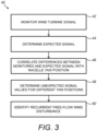
- a method of identifying recurrent free-flow wind disturbances associated with a wind turbine comprises monitoring a signal indicative of a parameter associated with operation of the wind turbine, determining an expected signal of the parameter based on the monitored signal, determining a difference between values of the monitored signal and the determined expected signal, and correlating the determined differences with yaw position of a nacelle of the wind turbine.
- the method includes determining, based on the correlated differences, unexpected values of the parameter for different yaw positions, and identifying, based on a frequency of occurrence of the determined unexpected values, a recurrent free-flow wind disturbance associated with a yaw position of the nacelle.
- the method may comprise a step of determining a normalised expected signal by normalising the expected signal based on a further signal indicative of a further parameter associated with operation of the wind turbine.
- the step of determining the expected signal may comprise determining one or more statistical properties of the monitored signal.
- the statistical properties include one or more of a statistical mean, a standard deviation, and a variance.
- the expected signal may be updated over time as the monitored signal is acquired.
- the expected signal is determined based on the monitored signal acquired in a prescribed time interval relative to, and prior to, a current time step.
- the step of determining unexpected values of the parameter may comprise determining, based on the correlated differences, a range of differences associated with normal operation of the wind turbine, and identifying correlated differences outside of the determined range to correspond to unexpected values of the parameter.
- the method may comprise a step of determining an intensity of the identified recurrent free-flow wind disturbance.
- the intensity may be based on a magnitude of the differences between the unexpected values and the expected signal.
- the method may comprise a step of determining a direction of the identified recurrent free-flow wind disturbance relative to the wind turbine.
- the direction may be determined as a derivative of the differences between the unexpected values and the expected signal with respect to a current yaw position of the nacelle.
- the method may comprise comparing measured wind turbine performance in the presence of the identified recurrent free-flow wind disturbance relative to an expected wind turbine performance.
- the method may comprise retaining the identified recurrent free-flow wind disturbance if a difference between the measured and expected wind turbine performance exceeds a prescribed performance threshold.
- wind turbine performance is a measure of power generated by the wind turbine or loading on one or more components of the wind turbine.
- the parameter may be one of: pitch angle of one or more rotor blades of the wind turbine; one or more loads on the rotor blades; acceleration of the top of a tower of the wind turbine; wind speed in the vicinity of the wind turbine; wind direction in the vicinity of the wind turbine; turbulence intensity in the vicinity of the wind turbine; and, grid power.
- the method may comprise performing the method steps for a plurality of different parameters.
- the method may comprise combining the identified recurrent free-flow wind disturbances for each of the different parameters to obtain an overall identification of one or more recurrent free-flow wind disturbances.
- the method may comprise determining a confidence level associated with the identified recurrent free-flow wind disturbance.
- the confidence level may be determined based on at least one of: a level of agreement between an output of the method steps for the plurality of different parameters; and, an amount of signal data on which the identification is based.
- the recurrent free-flow wind disturbance may be wake flow in the vicinity of the wind turbine.
- controlling operation of the wind turbine comprises at least one of controlling yaw position of the nacelle, controlling pitch angle of one or more wind turbine rotor blades, and controlling a speed of a generator of the wind turbine.
- a non-transitory, computer-readable storage medium storing instructions thereon that when executed by one or more processors cause the one or more processors to perform a method as described above.
- a controller for identifying recurrent free-flow wind disturbances associated with a wind turbine.
- the controller is configured to monitor a signal indicative of a parameter associated with operation of the wind turbine, determine an expected signal of the parameter based on the monitored signal, determine a difference between values of the monitored signal and the determined expected signal, and correlate the determined differences with yaw position of a nacelle of the wind turbine.
- the controller is configured to determine, based on the correlated differences, unexpected values of the parameter for different yaw positions, and identify, based on a frequency of occurrence of the determined unexpected values, a recurrent free-flow wind disturbance associated with a yaw position of the nacelle.
- a wind turbine comprising a controller as described above.
- wind field effects - or free-flow wind disturbances - in the vicinity of / proximal to a wind turbine can influence operation of the wind turbine, i.e. can cause changes in wind turbine states.
- certain wind field effects can negatively impact operating efficiency of the wind turbine, for instance by reducing the amount of wind energy being harvested by the wind turbine (and therefore reducing the power production of the wind turbine), and/or by increasing the loads experienced by components of the turbine (thereby potentially reducing lifespan of the components).
- wind field effects that are recurring, i.e. that are repeated in a predictable manner in certain operating conditions. It may therefore be possible to mitigate against the effects of such recurring wind field effects if their existence and effects can be predicted.
- One such recurring wind field effect is a static wake, detected over a longer period such that its future occurrence may be predictable. This would be in contrast to a new wake that is created in front of a wind turbine, and which is detected in real-time.
- the present invention provides for identifying recurrent free-flow wind disturbances (recurrent wind field effects) associated with a wind turbine.
- the invention is advantageous in that it provides for accurate identification of such recurrent disturbances - e.g. (static) wake flow - using the current hardware and signals of a wind turbine. That is, no external / additional hardware, such as sensors, are needed, thereby minimising costs. Also, no information external to the wind turbine is needed.
- the invention may therefore beneficially be retrofitted to / included in existing wind turbines.
- the invention is also advantageous in that it provides for real-time detection of wind field effects that may be recurring wind field effects. This is because the identification is based on measured or estimated signals from the wind turbine, e.g.
- the invention further advantageously identifies a recurrent wind field effect in association with at least one variable of the wind turbine operation.
- this variable is nacelle yaw position. This means that control of the wind turbine can be performed based on this association, for instance to avoid the wind turbine operating for extended periods at certain yaw positions of the nacelle.
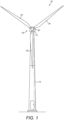
- FIG. 1 shows a wind turbine 10 in which an example of the disclosure may be incorporated.
- the wind turbine 10 comprises a tower 12 supporting a nacelle 14 to which a rotor 16 is mounted.
- the rotor 16 comprises a plurality of wind turbine blades 18 that extend radially from a hub 20.
- the rotor 16 comprises three blades 18 and a single rotor 16, although other configurations including any suitable number of blades and rotors are possible.
- the wind turbine 10 may be located on a wind farm (not shown) including a plurality of wind turbines. In particular, the wind turbine 10 may be located adjacent to one or more other wind turbines.
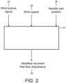
- FIG. 2 shows a wind turbine controller 22 in accordance with an example of the disclosure which may be implemented in the wind turbine 10 of Figure 1 .
- the controller 22 may be configured to output or transmit control signals for controlling operation of the wind turbine.
- the controller 22 may output signals to one or more actuator systems of the wind turbine 10 for adjusting a pitch angle of one or more of the rotor blades 18, and/or output signals to control a speed of a generator of the wind turbine 10.
- the controller 22 may output control signals to a yaw system of the wind turbine 10 to adjust a yaw position of the nacelle 14.
- the particular control signals, or other outputs, to be transmitted by the controller 22 may be determined by the controller 22 and be based on one or more inputs received by the controller 22. For instance, these inputs can include one or more measurements or signals received from sensors of the wind turbine 10, e.g. wind speed sensors, load sensors, accelerometers, etc.
- the controller 22 may be in the form of any suitable computing device, for instance one or more functional units or modules implemented on one or more computer processors. Such functional units may be provided by suitable software running on any suitable computing substrate using conventional or customer processors and memory. The one or more functional units may use a common computing substrate (for example, they may run on the same server) or separate substrates, or one or both may themselves be distributed between multiple computing devices.
- a computer memory may store instructions for performing the methods performed by the controller, and the processor(s) may execute the stored instructions to perform the method.
- the controller 22 illustrates inputs thereto, and outputs therefrom, for identifying recurrent wind field effects in accordance with an example of the invention.
- Figure 2 illustrates that the controller 22 receives the wind turbine signal 24.
- This signal can be indicative of how certain aspects of the wind turbine 10 is operating, and can include signals from one or more sensors of the wind turbine 10, for instance.
- the wind turbine signal 24 can include measured or estimated values of different parameters that are indicative of wind turbine operation, or that influence wind turbine operation.
- Such parameters can include one or more loads experienced by the rotor blades 18 (e.g. edgewise or flapwise loads), and a pitch angle of one or more of the rotor blades 18.
- the parameters can also include an acceleration of the top of the wind turbine tower 12, e.g.
- the parameters may include an intensity of turbulence that is present in the vicinity of the wind turbine 10, and a level of power that is being produced by the wind turbine 10 and provided to the grid.
- the parameters can also include environmental conditions in which the wind turbine 10 is operating, such as wind speed and/or wind direction. Some of the parameters may be directly measurable by sensors of the wind turbine (e.g. blade load sensors, accelerometers, etc), while some other parameters may be determined or estimated based on other sensor measurements and/or control signals output by the controller 22.
- the controller 22 may also receive an indication of wind speed 26 in the vicinity of the wind turbine 10. This may be obtained, for instance, from a suitable sensor of the wind turbine 10. In some examples, the wind speed is received by the controller 22 as part of the wind turbine signal 24.
- the controller 22 also receives an indication of the (current) yaw position of the nacelle 14 of the wind turbine 10. This may be in the form of a control signal indicative of a yaw position that the yaw system of the wind turbine 10 has controlled the nacelle 14 to assume.
- the controller 22 may output an indication of an identified recurrent free-flow disturbance, such as a static wake, determined based on the inputs.
- the indication may include determined details of the disturbance, such as one or more operating variables determined to be associated with the identified disturbance, as will be described below.
- the disturbance details may also include an intensity of the disturbance and/or a direction or location of the disturbance relative to the wind turbine 10, and may further include a confidence level indicative of a confidence that the identified disturbance is an accurate identification. This will be discussed further below.
- Figure 3 illustrates steps of a method 40, performed by the controller 22, for identifying recurrent free-flow wind disturbances in accordance with an example of the invention.
- the method 40 involves monitoring the signal 24 indicative of a parameter associated with operation of the wind turbine 10. Monitoring changes in the parameter - examples of which are provided above - over time can be used to identify the presence of wind field effects in the vicinity of the wind turbine 10, such as wake flow.
- the signal 24 may be monitored over a sufficiently long time period that typical values of the parameter in a variety of different wind turbine and environmental operating conditions may be ascertained and analysed. For instance, the initial monitoring may be over a period of a number of hours, but may typically be over a number of days or weeks.
- the monitored signal 24 is used to determine a so-called expected signal (or typical signal, or reference signal) of the parameter. This may involve recording one or more statistical properties of the monitored signal as the signal data is received by the controller 22.
- expected signal or typical signal, or reference signal
- wind turbines do not store acquired sensor signals for long periods of time, in order to reduce data storage requirements of the wind turbine 10. For instance, sensor data may be stored for a few hours - e.g. two hours - before being discarded. Therefore, it is generally not possible store all of the acquired data obtained while monitoring the wind turbine signal over an extended period and then determine the expected signal. Instead, the expected signal may be determined and updated (e.g.
- the expected signal may be in the form of (and therefore stored as) one or more statistical properties (statistical operation signals).
- Such properties can include a statistical mean, a standard deviation, a variance, or any other suitable statistical property of the monitored signal. It will be appreciated that storing determined statistical properties of a monitored signal in this way requires substantially less data storage than storing the monitored signal data itself.
- the expected signal may be updated to reflect all acquired data from when the wind turbine signal 24 starts being monitored. Alternatively, as the expected signal is updated to include the most recently acquired data, older data may be 'forgotten' so that it no longer contributes to the expected signal. Therefore, at any given time the expected signal may reflect monitored signal data acquired in a set period of time immediately prior to the current time.
- the expected signal is to be used as a reference point to identify when the monitored signal deviates from typical values thereof. This is because such deviation can be indicative of a change in wind turbine state caused by a wind field disturbance.
- a certain degree of variation in the monitored signal is to be expected during normal operation of the wind turbine 10 across different (but normal) operating conditions. Indeed, a different amount of variation in the monitored signal may be typical for different operating conditions.
- One example of such an operating condition is wind speed in the vicinity of the wind turbine 10. That is, different levels of variation in the monitored signal can be expected during normal operation of the wind turbine 10 for different wind speeds.
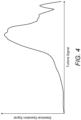
- Figure 4 illustrates an example of how the expected signal (statistical operation signal) may vary for different values of a particular wind turbine signal which, in this example, is different wind speeds.
- the parameter being monitored by the monitored signal is the pitch angle of the rotor blades 18, and the expected statistical variance of monitored values of the parameter is shown for different wind speeds.
- the variance in the monitored signal generally increases monotonically for increasing wind speed from 0 m/s to approximately 21 m/s.
- the variance generally decreases monotonically, before fluctuating between approximately 28 m/s and 30 m/s. It will be understood, therefore, that values of the monitored signal that deviate by a certain amount may be within a normal operating range for certain wind speeds, but outside of a normal operating range for other wind speeds.
- the expected signal may be normalised prior to being used to identify potential wind field disturbances.
- the expected signal may be normalised relative to (or based on) a dominant variable of wind turbine operation that causes fluctuation or variance in the monitored signal parameter.
- the expected signal is normalised based on the received or monitored wind speed 26 received by the controller 22; however, it will be appreciated that different variables or parameters may be used to normalise the expected signal.
- the particular parameter used for normalisation may be selected based on which variable or parameter is a dominant variable in the sense of impacting the results for the monitored variable.
- the expected signal can be used to determine whether parameter values from the monitored signal fall within an expected range for normal wind turbine operation, or whether they fall outside of the expected range, potentially indicating the presence of a wind field disturbance.
- the controller 22 determines a difference between values of the monitored signal and the determined expected signal.
- the determined differences are then correlated with yaw position 28 of the wind turbine nacelle 14, i.e. the yaw position of the nacelle 14 when the monitored signal value is acquired.
- the determined differences are binned against the yaw position of the nacelle 14, thereby mapping deviation from expected values for different nacelle positions. In this way, it can be ascertained whether certain yaw positions of the nacelle 14 are associated with deviations in the wind turbine signal, possibly as a result of wind field disturbances.
- Each bin can represent a suitable angle range of nacelle yaw position, e.g. each bin represent s a four-degree range, with bins being provided to cover the entire possible range of yaw positions of the nacelle 14.
- the controller 22 determines, based on the correlated differences, unexpected values of the parameter for different yaw positions. In particular, for each yaw position one or more statistical properties of the correlated differences may be determined. One or more techniques may then be applied to determine whether the correlated differences for each yaw position are larger than what would be expected during normal operation and, if so, this may be regarded as an unexpected signal.
- the controller 22 identifies, based on a frequency of occurrence of the determined unexpected values, a recurrent free-flow wind disturbance associated with a yaw position of the nacelle.
- the present disclosure is aimed at identifying wind field disturbances that occur over longer periods. For instance, the disclosure is aimed at identifying static wakes that impact on the performance of the wind turbine 10, rather than detection in real-time of a new wake created in front of the wind turbine 10.
- the method therefore analyses whether unexpected values or signals associated with a particular nacelle yaw position - i.e. a signal that is sufficiently different from the expected value - recur over time. If the unexpected signal is recorded as a moving variance, for instance, then a sufficiently high variance over time from the expected signal for a particular yaw position may indicate a relatively frequent occurrence of unexpected values at said yaw position, which may indicate the presence of a recurrent free-flow wind disturbance associated with said a yaw position.
- Figures 5(a) and 5(b) illustrate an example of the identification of wakes associated with certain nacelle yaw positions of the wind turbine 10, in accordance with the above-described method.
- the parameter being monitored by the monitored signal is the pitch angle of the rotor blades 18.
- Figure 5(a) illustrates a statistical operation signal - in this example, a moving variance of the blade pitch - for each yaw position of the nacelle 14. It may be seen that the variance is significantly higher for some yaw positions that others.
- Figure 5(a) indicates that in this example there are in fact static wakes associated with yaw positions corresponding to approximately 80 degree and approximately 230 degrees.
- the variance associated with some other yaw positions is also relatively high - e.g. a yaw position of approximately 200 degrees - and so the monitored signal is analysed in accordance with the above-described method in order to accurately identify yaw positions associated with wind field disturbances.
- the acquired signals are normalised based on a particular signal of the wind turbine which, in this example, is wind speed (as described above, and illustrated in Figure 4 ), and then the expected pattern or signal is removed from the monitored signal to indicate differences in the monitored signal from the expected signal for different yaw positions.
- the resulting signal is illustrated in Figure 5(b) .
- the method may include a step of determining an intensity of the identified disturbance.
- the intensity may be based on a magnitude of the differences between the unexpected values and the expected signal, e.g. a magnitude of the moving variance of the monitored signal.
- the differences may be normalised by (or relative to) the maximum absolute values, with peak intensity matching the (absolute) maximum difference to expected values.
- the intensity may be normalised to be between 0 and 1, for instance, with a disturbance intensity equal to 1 corresponding to the biggest spike, i.e. the biggest difference, and a disturbance intensity equal to 0 corresponding to no disturbance. This normalisation would need to be dynamic as it is unknown a priori what level of differences are to be expected.
- the method may include a step of determining a direction of the identified disturbance.
- the direction may be determined as a derivative of the differences between the unexpected values and the expected signal with respect to a current yaw position of the nacelle.
- the mapping of the deviation from expected values may be differentiated for the real-time nacelle yaw position and cross-referenced with the determined disturbance intensity.
- the disturbance direction may be determined to be one of left, centre or right relative to the wind turbine 10, in dependence on the determined derivative, e.g. an increasing difference with yaw position indicates 'left' and a decreasing difference with yaw position indicates 'right'. This may be represented by a range from -1 (left), through 0 (centre), to 1 (right).
- blade pitch angle is used as the parameter being monitored in the wind turbine signal in order to detect disturbances.
- many different parameters in the wind turbine signal may be used for this purpose.
- Figures 6(a) , 6(b) and 6(c) illustrate an example where the monitored parameter is side-to-side acceleration of the top of the wind turbine tower 12 (e.g. obtained from accelerometer measurements) in the case in which recurrent wake flow exists at the same yaw positions as Figure 5 , i.e. at approximately 80 and 230 degrees.
- Figure 6(a) illustrates a moving variance of the tower top acceleration (i.e. the statistical operation signal in this example) for each yaw position of the nacelle 14. It may be seen that the variance fluctuates to a greater degree for this parameter compared to for blade pitch (as illustrated in Figure 5(a) ).
- Figure 6(b) then illustrates how the expected signal for the tower top acceleration parameter may vary for different values of a particular wind turbine signal which, in this example, is different wind speeds.
- the monitored signal is normalised based on the monitored wind speed and the expected signal is removed from the monitored signal to obtain the moving variance signal illustrated in Figure 6(c) for different yaw position.
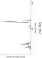
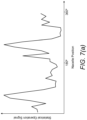
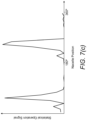
- Figures 7(a) , 7(b) and 7(c) illustrate an example where the monitored parameter is turbulence intensity in the case in which recurrent wake flow exists at approximately 80 and 230 degrees. As a wake will generate turbulence, then this parameter can also be useful for wake identification using the described method.
- Figure 7(a) illustrates a statistical operation signal in the form of a moving variance of the turbulence intensity for each yaw position of the nacelle 14
- Figure 7(b) illustrates how the expected signal for the turbulence intensity parameter varies for different wind speeds (i.e. the particular wind turbine signal in this example)
- Figure 7(c) illustrates the moving variance for different wind speeds after the monitored signal has been normalised by wind speed and the expected signal has been removed.
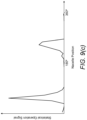
- Figures 8 and 9 illustrate further different parameters that may be monitored to identify recurrent wind field disturbances, specifically in the case in which recurrent wake flow exists at approximately 80 and 230 degrees.
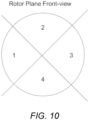
- Figures 8 and 9 illustrate examples in which the monitored parameter is loading on the wind turbine rotor blades 10.
- a wake will generate differences between forces applied to the rotor blades 18 in dependence on where a blade is positioned around its rotational path.
- Figure 10 schematically illustrates how the blade rotor plane may be split into quadrants, namely, left, right, upper and lower quadrants.
- the monitored parameter is a difference in blade loading between the left and right quadrants.
- Figure 8(a) illustrates a statistical operation signal in the form of a moving variance of the difference in blade loading between the left and right quadrants for each yaw position of the nacelle 14
- Figure 8(b) illustrates how the expected signal for the left-right loading difference parameter varies for different wind speeds (i.e. the particular wind turbine signal in this example)
- Figure 8(c) illustrates the moving variance for different wind speeds after the monitored signal has been normalised by wind speed and the expected signal has been removed.
- the monitored parameter is a difference in blade loading between the upper and lower quadrants.
- Figure 9(a) illustrates a statistical operation signal in the form of a moving variance of the difference in blade loading between the upper and lower quadrants for each yaw position of the nacelle 14
- Figure 9(b) illustrates an example of how the expected signal for the upper-lower loading difference parameter varies for different wind speeds (i.e. the particular wind turbine signal in this example)
- Figure 9(c) illustrates the moving variance for different wind speeds after the monitored signal has been normalised by wind speed and the expected signal has been removed.
- disturbances in the monitored signals may be identifiable to varying degrees for different monitored parameters. It may be that although there is general agreement between some of the different methods at certain points in time, there are differences between the results of different methods at other times.
- One option for improving the accuracy of identifications made according to the described method may be to combine or fuse together the results for different monitored parameters to make an overall identification of recurrent free-flow wind disturbances (as well as details such as their intensity, direction, etc.).
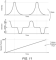
- Figure 11 illustrates plots of an example in which the identification results obtained based on different monitored parameters are combined, where Figure 11 in particular shows plots of wake intensity, direction and yaw position over time of an overall determination based on the individual results.
- the slope of the intensity in the first plot provides the direction of the disturbance in the second plot, where a value of -1 in the second plot indicates that the disturbance is to the left of the turbine 10 and a value of +1 indicates that the disturbance is to the right of the turbine 10.
- individual methods are combined, and in particular the results are combined using a simple weighted average.
- the weights associated with certain monitored parameter results may greater than for others if certain parameters tend to provide more accurate results than others.
- the method may further include determining a confidence level associated with the identified recurrent free-flow wind disturbance.
- This confidence level can indicate a level of certainty the method has in the accuracy of an identified disturbance, and its particular characteristics (intensity, etc.).
- the confidence level may be determined based on a level of agreement between the different methods. A greater level of agreement in the results of different methods may correspond to a greater confidence level being associated with the results.
- the confidence level may alternatively or additionally be determined based on an amount of signal data on which the identification analysis is based.
- the identification may have been made on the basis of limited data.
- an identification made on this basis may have a lower confidence level associated therewith than one made on the basis of a larger monitored data set.
- recurrent free-flow wind disturbances may be desirable because they can negatively impact the capability of a wind turbine to operate efficiently, for instance to maximise power production for the grid or minimise loading on the wind turbine components.
- one option may be to compare a measured wind turbine performance (e.g. power production to the grid, component loading, etc.) in the presence of the identified recurrent free-flow wind disturbance relative to an expected wind turbine performance in such operating conditions. If the identified disturbance does not in fact appear to significantly influence wind turbine performance then the identified disturbance may be discarded, or may not be considered in ongoing or future control of the wind turbine. On the other hand, if a difference between the measured and expected wind turbine performance exceeds a prescribed performance threshold, then the identified disturbance may be retained and taken into consideration for determining control steps performed by the turbine.
- a measured wind turbine performance e.g. power production to the grid, component loading, etc.
- operation of the wind turbine 10 may be controlled based on the identified recurrent free-flow wind disturbance. This may include controlling yaw position of the nacelle 14, controlling pitch angle of one or more of the wind turbine rotor blades 18, and/or controlling a speed of a generator of the wind turbine 10, for instance.
- the identified recurrent free-flow wind disturbance may also be used when designing a layout of a wind farm, for instance to position turbines relative to each other to reduce the impact of wakes generated by one turbine on other, adjacent turbines, so as to optimise operating efficiency of the wind farm, thereby maximising the economic returns of a wind farm.
- a wake (or other wind field effect) is identified as being associated with a particular yaw position of the wind turbine nacelle.
- wind field effects may be identified in association with different variables associated with the wind turbine.
- wind field effects could be identified in association with an absolute wind direction in the vicinity of the wind turbine.
- the variable considered in this regard may be an independent variable, i.e. one for which a degree of control is possible, such that the effects of an identified wind field effect may be mitigated.
- wind field effects in association with a plurality of different variables may also be considered.
Landscapes
- Engineering & Computer Science (AREA)
- Mechanical Engineering (AREA)
- Life Sciences & Earth Sciences (AREA)
- Sustainable Development (AREA)
- Sustainable Energy (AREA)
- Chemical & Material Sciences (AREA)
- Combustion & Propulsion (AREA)
- General Engineering & Computer Science (AREA)
- Evolutionary Computation (AREA)
- Theoretical Computer Science (AREA)
- Artificial Intelligence (AREA)
- Health & Medical Sciences (AREA)
- Toxicology (AREA)
- Wind Motors (AREA)
Claims (15)
- Verfahren zum Identifizieren von wiederkehrenden Störungen der freien Windströmung, die mit einer Windkraftanlage (10) zusammenhängen, wobei das Verfahren den Schritt umfasst zum:Überwachen (42) eines Signals, das auf einen Parameter hinweist, der mit dem Betrieb der Windkraftanlage zusammenhängt;wobei das Verfahren dadurch gekennzeichnet ist, dass es die Schritte umfasst zum:Bestimmen (44) eines erwarteten Signals des Parameters basierend auf dem überwachten Signal;Bestimmen einer Differenz zwischen Werten des überwachten Signals und des bestimmten erwarteten Signals und Korrelieren (46) der bestimmten Differenzen mit der Gier-Position einer Gondel der Windkraftanlage;Bestimmen (48) von unerwarteten Werten des Parameters für unterschiedliche Gier-Positionen basierend auf den korrelierten Differenzen; undIdentifizieren (50), basierend auf einer Häufigkeit des Auftretens der bestimmten unerwarteten Werte, einer wiederkehrenden Störung der freien Windströmung, die mit einer Gier-Position der Gondel zusammenhängt.
- Verfahren nach Anspruch 1, wobei das Verfahren einen Schritt des Bestimmens eines normalisierten erwarteten Signals durch Normalisieren des erwarteten Signals basierend auf einem weiteren Signal umfasst, das auf einen weiteren Parameter hinweist, der mit dem Betrieb der Windkraftanlage zusammenhängt, wobei das Bestimmen der Differenzen das Vergleichen von Werten des überwachten Signals, das basierend auf dem weiteren Signal normalisiert wurde, und des bestimmten normalisierten erwarteten Signals umfasst.
- Verfahren nach Anspruch 1 oder Anspruch 2, wobei der Schritt des Bestimmens des erwarteten Signals das Bestimmen einer oder mehrerer statistischer Eigenschaften des überwachten Signals umfasst; wobei die statistischen Eigenschaften optional eines oder mehrere von einem statistischen Mittel, einer Standardabweichung und einer Varianz beinhalten.
- Verfahren nach einem vorstehenden Anspruch, wobei das erwartete Signal über die Zeit hinweg aktualisiert wird, wenn das überwachte Signal erfasst wird; wobei das erwartete Signal optional basierend auf dem überwachten Signal, das in einem vorgeschriebenen Zeitintervall in Bezug auf den und vor einem aktuellen Zeitschritt erfasst wurde, bestimmt wird.
- Verfahren nach einem vorstehenden Anspruch, wobei der Schritt des Bestimmens von unerwarteten Werten des Parameters das Bestimmen eines Bereichs von Differenzen, die mit dem Normalbetrieb der Windkraftanlage zusammenhängen, basierend auf den korrelierten Differenzen, und das Identifizieren von korrelierten Differenzen außerhalb des bestimmten Bereichs umfasst, um unerwarteten Werten des Parameters zu entsprechen.
- Verfahren nach einem vorstehenden Anspruch, wobei das Verfahren einen Schritt des Bestimmens einer Intensität der identifizierten wiederkehrenden Störung der freien Windströmung umfasst, wobei die Intensität auf einer Größe der Differenzen zwischen den unerwarteten Werten und dem erwarteten Signal basiert.
- Verfahren nach einem vorstehenden Anspruch, wobei das Verfahren einen Schritt des Bestimmens einer Richtung der identifizierten wiederkehrenden Störung der freien Windströmung in Bezug zur Windkraftanlage umfasst, wobei die Richtung als Ableitung der Differenzen zwischen den unerwarteten Werten und dem erwarteten Signal in Bezug auf eine aktuelle Gier-Position der Gondel bestimmt wird.
- Verfahren nach einem vorstehenden Anspruch, wobei das Verfahren das Vergleichen einer gemessenen Windkraftanlagenleistung in Gegenwart der identifizierten wiederkehrenden Störung der freien Windströmung in Bezug zu einer erwarteten Windkraftanlagenleistung, und das Beibehalten der identifizierten wiederkehrenden Störung der freien Windströmung umfasst, wenn eine Differenz zwischen der gemessenen und erwarteten Windkraftanlagenleistung eine vorgeschriebene Leistungsschwelle überschreitet; wobei die Windkraftanlagenleistung optional die von der Windkraftanlage erzeugte Leistung oder die Belastung auf einer oder mehreren Komponenten der Windkraftanlage ist.
- Verfahren nach einem vorstehenden Anspruch, wobei der Parameter eines ist von:Blattwinkel eines oder mehrerer Rotorblätter der Windkraftanlage;einer oder mehreren Lasten auf den Rotorblättern;Beschleunigung der Spitze eines Turms der Windkraftanlage;Windgeschwindigkeit in der Nähe der Windkraftanlage;Windrichtung in der Nähe der Windkraftanlage;Turbulenzintensität in der Nähe der Windkraftanlage; undNetzleistung.
- Verfahren nach einem vorstehenden Anspruch, wobei das Verfahren Durchführen der Verfahrensschritte für eine Vielzahl von unterschiedlichen Parametern und das Kombinieren der identifizierten wiederkehrenden Störungen der freien Windströmung für jeden der unterschiedlichen Parameter umfasst, um eine Gesamtidentifikation einer oder mehrerer wiederkehrender Störungen der freien Windströmung zu erhalten.
- Verfahren nach einem vorstehenden Anspruch, wobei das Verfahren das Bestimmen einer Vertrauensstufe umfasst, die mit der identifizierten wiederkehrenden Störung der freien Windströmung zusammenhängt, wobei die Vertrauensstufe basierend auf mindestens einem bestimmt wird von:wenn von Anspruch 9 abhängig, einer Übereinstimmungsstufe zwischen einem Ausgang der Verfahrensschritte für die Vielzahl von unterschiedlichen Parametern; undeiner Menge von Signaldaten, auf denen die Identifizierung basiert.
- Verfahren nach einem vorstehenden Anspruch, wobei die wiederkehrende Störung der freien Windströmung eine Nachlaufströmung in der Nähe der Windkraftanlage ist.
- Verfahren nach einem vorstehenden Anspruch, wobei das Verfahren das Steuern des Betriebs der Windkraftanlage basierend auf identifizierten wiederkehrenden Störung der freien Windströmung umfasst; wobei das Steuern des Betriebs der Windkraftanlage optional mindestens eines von Steuern der Gier-Position der Gondel, Steuern des Blattwinkels eines oder mehrerer Windkraftanlagen-Rotorblätter, und Steuern einer Geschwindigkeit eines Generators der Windkraftanlage umfasst.
- Steuereinheit (22) zum Identifizieren von wiederkehrenden Störungen der freien Windströmung, die mit einer Windkraftanlage zusammenhängen, wobei die Steuereinheit konfiguriert ist, um:ein Signal zu überwachen (42), das auf einen Parameter hinweist, der mit dem Betrieb der Windkraftanlage zusammenhängt;wobei die Steuereinheit dadurch gekennzeichnet ist, dass sie weiter konfiguriert ist, um:basierend auf dem überwachten Signal ein erwartetes Signal des Parameters zu bestimmen (44);eine Differenz zwischen Werten des überwachten Signals und des bestimmten erwarteten Signals zu bestimmen und die bestimmten Differenzen mit einer Gier-Position einer Gondel der Windkraftanlage zu korrelieren (46);basierend auf den korrelierten Differenzen unerwartete Werte des Parameters für unterschiedliche Gier-Positionen zu bestimmen (48); undbasierend auf einer Häufigkeit des Auftretens der bestimmten unerwarteten Werte eine wiederkehrende Störung der freien Windströmung, die mit einer Gier-Position der Gondel zusammenhängt, zu identifizieren (50).
- Windkraftanlage (20), die eine Steuereinheit nach Anspruch 14 umfasst.
Applications Claiming Priority (2)
| Application Number | Priority Date | Filing Date | Title |
|---|---|---|---|
| DKPA202170423 | 2021-08-25 | ||
| PCT/DK2022/050173 WO2023025365A1 (en) | 2021-08-25 | 2022-08-25 | Identifying recurrent free-flow wind disturbances associated with a wind turbine |
Publications (3)
| Publication Number | Publication Date |
|---|---|
| EP4392669A1 EP4392669A1 (de) | 2024-07-03 |
| EP4392669B1 true EP4392669B1 (de) | 2025-03-12 |
| EP4392669C0 EP4392669C0 (de) | 2025-03-12 |
Family
ID=83191981
Family Applications (1)
| Application Number | Title | Priority Date | Filing Date |
|---|---|---|---|
| EP22764647.8A Active EP4392669B1 (de) | 2021-08-25 | 2022-08-25 | Identifizierung von wiederkehrenden freistromwindstörungen im zusammenhang mit einer windturbine |
Country Status (5)
| Country | Link |
|---|---|
| US (1) | US12247547B2 (de) |
| EP (1) | EP4392669B1 (de) |
| CN (1) | CN117836514A (de) |
| ES (1) | ES3017814T3 (de) |
| WO (1) | WO2023025365A1 (de) |
Families Citing this family (2)
| Publication number | Priority date | Publication date | Assignee | Title |
|---|---|---|---|---|
| CN118210086B (zh) * | 2024-05-22 | 2024-08-30 | 南京气象科技创新研究院 | 基于湿位涡的集合预报扰动方法 |
| WO2026008115A1 (en) | 2024-07-04 | 2026-01-08 | Vestas Wind Systems A/S | Calibrating a sensor of a wind turbine |
Family Cites Families (8)
| Publication number | Priority date | Publication date | Assignee | Title |
|---|---|---|---|---|
| US10100813B2 (en) | 2014-11-24 | 2018-10-16 | General Electric Company | Systems and methods for optimizing operation of a wind farm |
| DK3225837T3 (da) | 2016-03-30 | 2022-10-31 | Siemens Gamesa Renewable Energy As | Fremgangsmåde og anordning til kontinuerlig kalibrering af en vindretningsmåling |
| DK201670197A1 (en) | 2016-04-04 | 2017-10-23 | Mita-Teknik As | A system and a method for optimal yaw control |
| WO2018059641A1 (en) | 2016-09-29 | 2018-04-05 | Vestas Wind Systems A/S | Control method for a wind turbine |
| EP3536948A1 (de) | 2018-03-08 | 2019-09-11 | Siemens Gamesa Renewable Energy A/S | Bestimmung von steuerungseinstellungen für eine windturbine |
| EP3620649A1 (de) * | 2018-09-10 | 2020-03-11 | Siemens Gamesa Renewable Energy A/S | Steuerung von windturbinen in gegenwart von nachlaufimplikationen |
| EP3859147A1 (de) * | 2020-02-03 | 2021-08-04 | Ventus Engineering GmbH | Wecküberwachung, weckverwaltung und sensorische anordnungen dafür |
| US11231012B1 (en) * | 2020-09-22 | 2022-01-25 | General Electric Renovables Espana, S.L. | Systems and methods for controlling a wind turbine |
-
2022
- 2022-08-25 EP EP22764647.8A patent/EP4392669B1/de active Active
- 2022-08-25 CN CN202280057581.5A patent/CN117836514A/zh active Pending
- 2022-08-25 ES ES22764647T patent/ES3017814T3/es active Active
- 2022-08-25 US US18/686,367 patent/US12247547B2/en active Active
- 2022-08-25 WO PCT/DK2022/050173 patent/WO2023025365A1/en not_active Ceased
Also Published As
| Publication number | Publication date |
|---|---|
| US20240401571A1 (en) | 2024-12-05 |
| WO2023025365A1 (en) | 2023-03-02 |
| EP4392669A1 (de) | 2024-07-03 |
| EP4392669C0 (de) | 2025-03-12 |
| ES3017814T3 (en) | 2025-05-13 |
| US12247547B2 (en) | 2025-03-11 |
| CN117836514A (zh) | 2024-04-05 |
Similar Documents
| Publication | Publication Date | Title |
|---|---|---|
| EP4130459B1 (de) | Windturbinengeneratorsystem und steuerungsverfahren, steuergerät und steuerungssystem dafür | |
| US9366235B2 (en) | Estimation of wind conditions at a wind turbine | |
| DK1132614T3 (en) | A regulating system for a wind power plant | |
| EP2886853B1 (de) | Überwachungssystem und Überwachungsverfahren für einen Windturbinengenerator | |
| CN110168220B (zh) | 一种评估风力涡轮机发电机性能的方法和系统 | |
| US9086337B2 (en) | Detecting a wake situation in a wind farm | |
| TWI788290B (zh) | 風力渦輪機偏航失準估測 | |
| US10883475B2 (en) | Method for monitoring and assessing power performance changes of a wind turbine | |
| EP4194684B1 (de) | Laststeuerungsverfahren und -vorrichtung für ein windturbinengeneratorsystem | |
| EP4392669B1 (de) | Identifizierung von wiederkehrenden freistromwindstörungen im zusammenhang mit einer windturbine | |
| EP3623616A1 (de) | Erfassung abnormaler bedingungen in einem windturbinengenerator | |
| CN113574272B (zh) | 用于识别在风能设施上积冰的方法 | |
| CN108291527A (zh) | 一种监测和评估风力涡轮机功率性能变化的方法 | |
| WO2018059259A1 (en) | Method and system of yaw control of wind turbines in a wind turbine farm | |
| EP3249217A1 (de) | Verfahren zur identifizierung eines windverteilungsmusters über der rotorfläche und eine windturbine damit | |
| US20210148336A1 (en) | A method for determining wind turbine blade edgewise load recurrence | |
| EP3983672B1 (de) | Verfahren zur steuerung eines windparks unter turbulenten windverhältnissen | |
| US20230026286A1 (en) | Method for computer-implemented monitoring of a wind turbine | |
| US20110153097A1 (en) | System for triggering an emergency system of a wind turbine | |
| CN113027698A (zh) | 风力发电机组的变桨控制回路异常的检测方法和装置 | |
| CN119593968A (zh) | 一种基于振动的风电机组桨叶异常检测方法及系统 | |
| CN121958924A (zh) | 一种基于多源数据的风电功率优化方法及相关设备 | |
| CN120720167A (zh) | 复杂风况下液压变桨控制方法及系统 |
Legal Events
| Date | Code | Title | Description |
|---|---|---|---|
| STAA | Information on the status of an ep patent application or granted ep patent |
Free format text: STATUS: UNKNOWN |
|
| STAA | Information on the status of an ep patent application or granted ep patent |
Free format text: STATUS: THE INTERNATIONAL PUBLICATION HAS BEEN MADE |
|
| PUAI | Public reference made under article 153(3) epc to a published international application that has entered the european phase |
Free format text: ORIGINAL CODE: 0009012 |
|
| STAA | Information on the status of an ep patent application or granted ep patent |
Free format text: STATUS: REQUEST FOR EXAMINATION WAS MADE |
|
| 17P | Request for examination filed |
Effective date: 20240208 |
|
| AK | Designated contracting states |
Kind code of ref document: A1 Designated state(s): AL AT BE BG CH CY CZ DE DK EE ES FI FR GB GR HR HU IE IS IT LI LT LU LV MC MK MT NL NO PL PT RO RS SE SI SK SM TR |
|
| DAV | Request for validation of the european patent (deleted) | ||
| DAX | Request for extension of the european patent (deleted) | ||
| GRAP | Despatch of communication of intention to grant a patent |
Free format text: ORIGINAL CODE: EPIDOSNIGR1 |
|
| STAA | Information on the status of an ep patent application or granted ep patent |
Free format text: STATUS: GRANT OF PATENT IS INTENDED |
|
| INTG | Intention to grant announced |
Effective date: 20241218 |
|
| GRAS | Grant fee paid |
Free format text: ORIGINAL CODE: EPIDOSNIGR3 |
|
| GRAA | (expected) grant |
Free format text: ORIGINAL CODE: 0009210 |
|
| STAA | Information on the status of an ep patent application or granted ep patent |
Free format text: STATUS: THE PATENT HAS BEEN GRANTED |
|
| AK | Designated contracting states |
Kind code of ref document: B1 Designated state(s): AL AT BE BG CH CY CZ DE DK EE ES FI FR GB GR HR HU IE IS IT LI LT LU LV MC MK MT NL NO PL PT RO RS SE SI SK SM TR |
|
| REG | Reference to a national code |
Ref country code: GB Ref legal event code: FG4D |
|
| REG | Reference to a national code |
Ref country code: CH Ref legal event code: EP |
|
| REG | Reference to a national code |
Ref country code: DE Ref legal event code: R096 Ref document number: 602022011788 Country of ref document: DE |
|
| REG | Reference to a national code |
Ref country code: IE Ref legal event code: FG4D |
|
| U01 | Request for unitary effect filed |
Effective date: 20250321 |
|
| U07 | Unitary effect registered |
Designated state(s): AT BE BG DE DK EE FI FR IT LT LU LV MT NL PT RO SE SI Effective date: 20250327 |
|
| REG | Reference to a national code |
Ref country code: ES Ref legal event code: FG2A Ref document number: 3017814 Country of ref document: ES Kind code of ref document: T3 Effective date: 20250513 |
|
| PG25 | Lapsed in a contracting state [announced via postgrant information from national office to epo] |
Ref country code: RS Free format text: LAPSE BECAUSE OF FAILURE TO SUBMIT A TRANSLATION OF THE DESCRIPTION OR TO PAY THE FEE WITHIN THE PRESCRIBED TIME-LIMIT Effective date: 20250612 |
|
| PG25 | Lapsed in a contracting state [announced via postgrant information from national office to epo] |
Ref country code: NO Free format text: LAPSE BECAUSE OF FAILURE TO SUBMIT A TRANSLATION OF THE DESCRIPTION OR TO PAY THE FEE WITHIN THE PRESCRIBED TIME-LIMIT Effective date: 20250612 |
|
| PG25 | Lapsed in a contracting state [announced via postgrant information from national office to epo] |
Ref country code: HR Free format text: LAPSE BECAUSE OF FAILURE TO SUBMIT A TRANSLATION OF THE DESCRIPTION OR TO PAY THE FEE WITHIN THE PRESCRIBED TIME-LIMIT Effective date: 20250312 |
|
| PG25 | Lapsed in a contracting state [announced via postgrant information from national office to epo] |
Ref country code: GR Free format text: LAPSE BECAUSE OF FAILURE TO SUBMIT A TRANSLATION OF THE DESCRIPTION OR TO PAY THE FEE WITHIN THE PRESCRIBED TIME-LIMIT Effective date: 20250613 |
|
| U20 | Renewal fee for the european patent with unitary effect paid |
Year of fee payment: 4 Effective date: 20250825 |
|
| PG25 | Lapsed in a contracting state [announced via postgrant information from national office to epo] |
Ref country code: SM Free format text: LAPSE BECAUSE OF FAILURE TO SUBMIT A TRANSLATION OF THE DESCRIPTION OR TO PAY THE FEE WITHIN THE PRESCRIBED TIME-LIMIT Effective date: 20250312 |
|
| PGFP | Annual fee paid to national office [announced via postgrant information from national office to epo] |
Ref country code: ES Payment date: 20250916 Year of fee payment: 4 |
|
| PG25 | Lapsed in a contracting state [announced via postgrant information from national office to epo] |
Ref country code: PL Free format text: LAPSE BECAUSE OF FAILURE TO SUBMIT A TRANSLATION OF THE DESCRIPTION OR TO PAY THE FEE WITHIN THE PRESCRIBED TIME-LIMIT Effective date: 20250312 |
|
| PG25 | Lapsed in a contracting state [announced via postgrant information from national office to epo] |
Ref country code: CZ Free format text: LAPSE BECAUSE OF FAILURE TO SUBMIT A TRANSLATION OF THE DESCRIPTION OR TO PAY THE FEE WITHIN THE PRESCRIBED TIME-LIMIT Effective date: 20250312 |
|
| PG25 | Lapsed in a contracting state [announced via postgrant information from national office to epo] |
Ref country code: SK Free format text: LAPSE BECAUSE OF FAILURE TO SUBMIT A TRANSLATION OF THE DESCRIPTION OR TO PAY THE FEE WITHIN THE PRESCRIBED TIME-LIMIT Effective date: 20250312 |
|
| PG25 | Lapsed in a contracting state [announced via postgrant information from national office to epo] |
Ref country code: IS Free format text: LAPSE BECAUSE OF FAILURE TO SUBMIT A TRANSLATION OF THE DESCRIPTION OR TO PAY THE FEE WITHIN THE PRESCRIBED TIME-LIMIT Effective date: 20250712 |
|
| PLBE | No opposition filed within time limit |
Free format text: ORIGINAL CODE: 0009261 |
|
| STAA | Information on the status of an ep patent application or granted ep patent |
Free format text: STATUS: NO OPPOSITION FILED WITHIN TIME LIMIT |
|
| REG | Reference to a national code |
Ref country code: CH Ref legal event code: L10 Free format text: ST27 STATUS EVENT CODE: U-0-0-L10-L00 (AS PROVIDED BY THE NATIONAL OFFICE) Effective date: 20260121 |
|
| 26N | No opposition filed |
Effective date: 20251215 |
|
| REG | Reference to a national code |
Ref country code: CH Ref legal event code: H13 Free format text: ST27 STATUS EVENT CODE: U-0-0-H10-H13 (AS PROVIDED BY THE NATIONAL OFFICE) Effective date: 20260324 |
|
| PG25 | Lapsed in a contracting state [announced via postgrant information from national office to epo] |
Ref country code: MC Free format text: LAPSE BECAUSE OF FAILURE TO SUBMIT A TRANSLATION OF THE DESCRIPTION OR TO PAY THE FEE WITHIN THE PRESCRIBED TIME-LIMIT Effective date: 20250312 |