EP4392233B1 - 3d-drucker - Google Patents
3d-drucker Download PDFInfo
- Publication number
- EP4392233B1 EP4392233B1 EP22768376.0A EP22768376A EP4392233B1 EP 4392233 B1 EP4392233 B1 EP 4392233B1 EP 22768376 A EP22768376 A EP 22768376A EP 4392233 B1 EP4392233 B1 EP 4392233B1
- Authority
- EP
- European Patent Office
- Prior art keywords
- temperature
- printing
- sensor
- temperature sensor
- printer
- Prior art date
- Legal status (The legal status is an assumption and is not a legal conclusion. Google has not performed a legal analysis and makes no representation as to the accuracy of the status listed.)
- Active
Links
Images
Classifications
-
- B—PERFORMING OPERATIONS; TRANSPORTING
- B29—WORKING OF PLASTICS; WORKING OF SUBSTANCES IN A PLASTIC STATE IN GENERAL
- B29C—SHAPING OR JOINING OF PLASTICS; SHAPING OF MATERIAL IN A PLASTIC STATE, NOT OTHERWISE PROVIDED FOR; AFTER-TREATMENT OF THE SHAPED PRODUCTS, e.g. REPAIRING
- B29C64/00—Additive manufacturing, i.e. manufacturing of three-dimensional [3D] objects by additive deposition, additive agglomeration or additive layering, e.g. by 3D printing, stereolithography or selective laser sintering
- B29C64/30—Auxiliary operations or equipment
- B29C64/386—Data acquisition or data processing for additive manufacturing
- B29C64/393—Data acquisition or data processing for additive manufacturing for controlling or regulating additive manufacturing processes
-
- B—PERFORMING OPERATIONS; TRANSPORTING
- B29—WORKING OF PLASTICS; WORKING OF SUBSTANCES IN A PLASTIC STATE IN GENERAL
- B29C—SHAPING OR JOINING OF PLASTICS; SHAPING OF MATERIAL IN A PLASTIC STATE, NOT OTHERWISE PROVIDED FOR; AFTER-TREATMENT OF THE SHAPED PRODUCTS, e.g. REPAIRING
- B29C64/00—Additive manufacturing, i.e. manufacturing of three-dimensional [3D] objects by additive deposition, additive agglomeration or additive layering, e.g. by 3D printing, stereolithography or selective laser sintering
- B29C64/20—Apparatus for additive manufacturing; Details thereof or accessories therefor
- B29C64/205—Means for applying layers
- B29C64/209—Heads; Nozzles
-
- B—PERFORMING OPERATIONS; TRANSPORTING
- B29—WORKING OF PLASTICS; WORKING OF SUBSTANCES IN A PLASTIC STATE IN GENERAL
- B29C—SHAPING OR JOINING OF PLASTICS; SHAPING OF MATERIAL IN A PLASTIC STATE, NOT OTHERWISE PROVIDED FOR; AFTER-TREATMENT OF THE SHAPED PRODUCTS, e.g. REPAIRING
- B29C64/00—Additive manufacturing, i.e. manufacturing of three-dimensional [3D] objects by additive deposition, additive agglomeration or additive layering, e.g. by 3D printing, stereolithography or selective laser sintering
- B29C64/20—Apparatus for additive manufacturing; Details thereof or accessories therefor
- B29C64/295—Heating elements
-
- B—PERFORMING OPERATIONS; TRANSPORTING
- B33—ADDITIVE MANUFACTURING TECHNOLOGY
- B33Y—ADDITIVE MANUFACTURING, i.e. MANUFACTURING OF THREE-DIMENSIONAL [3-D] OBJECTS BY ADDITIVE DEPOSITION, ADDITIVE AGGLOMERATION OR ADDITIVE LAYERING, e.g. BY 3-D PRINTING, STEREOLITHOGRAPHY OR SELECTIVE LASER SINTERING
- B33Y50/00—Data acquisition or data processing for additive manufacturing
- B33Y50/02—Data acquisition or data processing for additive manufacturing for controlling or regulating additive manufacturing processes
-
- B—PERFORMING OPERATIONS; TRANSPORTING
- B29—WORKING OF PLASTICS; WORKING OF SUBSTANCES IN A PLASTIC STATE IN GENERAL
- B29C—SHAPING OR JOINING OF PLASTICS; SHAPING OF MATERIAL IN A PLASTIC STATE, NOT OTHERWISE PROVIDED FOR; AFTER-TREATMENT OF THE SHAPED PRODUCTS, e.g. REPAIRING
- B29C64/00—Additive manufacturing, i.e. manufacturing of three-dimensional [3D] objects by additive deposition, additive agglomeration or additive layering, e.g. by 3D printing, stereolithography or selective laser sintering
- B29C64/10—Processes of additive manufacturing
- B29C64/106—Processes of additive manufacturing using only liquids or viscous materials, e.g. depositing a continuous bead of viscous material
- B29C64/118—Processes of additive manufacturing using only liquids or viscous materials, e.g. depositing a continuous bead of viscous material using filamentary material being melted, e.g. fused deposition modelling [FDM]
-
- B—PERFORMING OPERATIONS; TRANSPORTING
- B33—ADDITIVE MANUFACTURING TECHNOLOGY
- B33Y—ADDITIVE MANUFACTURING, i.e. MANUFACTURING OF THREE-DIMENSIONAL [3-D] OBJECTS BY ADDITIVE DEPOSITION, ADDITIVE AGGLOMERATION OR ADDITIVE LAYERING, e.g. BY 3-D PRINTING, STEREOLITHOGRAPHY OR SELECTIVE LASER SINTERING
- B33Y30/00—Apparatus for additive manufacturing; Details thereof or accessories therefor
Definitions
- the invention relates to a 3D printer extruder unit, and a 3D printer comprising a 3D printer extruder unit.
- 3D printing is seen as a way forward to allow the flexible production of limited editions of components and products in a cost-effective manner.
- FDM Fused Deposition Modelling
- US 10265911 B1 discloses apparatuses and techniques for using an image-based monitoring and feedback system for three-dimensional printing.
- a camera captures images of objects being printed and an image-processing system compares the images with benchmark images to detect and correct differences between the object and the benchmark. The correction can be in real-time or applied to subsequent printing.
- Other aspects include a calibration system that prints predefined test objects and compares them to benchmarks to ensure that the printer operating parameters are properly set. The comparison can be manually performed by a user or automated as a part of the image-processing system.
- US-2021/170682 discloses a method of forming a part via additive manufacturing.
- the method includes depositing a first layer of thermoplastic material along a first path via an extruder head, initiating deposition of a second layer of thermoplastic material along a second path via the extruder head, and monitoring a thermal profile of the first layer along the first path while the second layer is deposited.
- One or more thermal imaging sensors may be positioned relative to a work area and layers such that they are configured to acquire thermal data associated with the part as it is being additively manufactured.
- the processing unit may monitor the temperature and in case of the temperature going away or deviates from an acceptable range, it notifies an operator or directly controls one or more printing parameters of the 3D printer to correct the temperature error, thereby avoiding processing error.
- the processing unit may monitor the temperature and in case of the temperature going away or deviates from an acceptable range, it notifies an operator or directly controls one or more printing parameters of the 3D printer to correct the temperature error, thereby avoiding processing error.
- the processing unit may monitor the temperature and in case of the temperature going away or deviates from an acceptable range, it notifies an operator or directly controls one or more printing parameters of the 3D printer to correct the temperature error, thereby avoiding processing error.
- at least one sensor has a good field of view of the printing material deposited by the printing nozzle, especially in situations where complex geometrical structures are printed and it may be vital to have the sensors arranged to measure on different positions to achieve a good field of view. Having a good field of view helps in achieving a good signal to noise ratio, thus allowing for further
- the printing nozzle may be configured for being used in, but not limited to Fused Deposition Modelling (FDM).
- FDM Fused Deposition Modelling
- the printing nozzle may be configured to receive a thermoplastic filament, heat the filament to melt the filament, and then extrude the melted filament through the printing nozzle to deposit the melted filament.
- the melted filament is deposited layer-by-layer to achieve the desired shape.
- the first temperature sensor and the second temperature sensor may be arranged at or near the printing nozzle.
- the first temperature sensor and the second temperature sensor may be arranged to move together with the printing nozzle during a printing process.
- the comparison of the sensor data to a predefined threshold data may be performed on the sensor signal information. Thereby, the translation of the sensor signal information into temperature, which would require detailed analysis, may be omitted.
- a comparison of the sensor data to a predefined threshold data may be performed by the processing unit interpreting the sensor data to convert or translate it into a temperature. That may, however, require a few assumed or predetermined additional values for reference purposes.
- the sensor data may be temperature data and the predefined threshold data may be a predefined temperature threshold.
- the processing unit may in an embodiment be configured to compare the sensor data to a predefined threshold data by interpreting the sensor data to provide temperature data and compare the temperature data to a predefined temperature threshold data.
- the 3D printer extruder unit may comprise three, four, five, or more temperature sensors each configured for measuring the temperature of deposited material at different positions.
- the processing unit is a unit comprising any circuit and/or device suitably adapted to perform the functions described herein.
- the control unit may comprise general-purpose or proprietary programmable microprocessors, such as Digital Signal Processors (DSP), Application-Specific Integrated Circuits (ASIC), Programmable Logic Arrays (PLA), Field Programmable Gate Arrays (FPGA), special-purpose electronic circuits, etc., or a combination thereof.
- DSP Digital Signal Processors
- ASIC Application-Specific Integrated Circuits
- PDA Programmable Logic Arrays
- FPGA Field Programmable Gate Arrays
- special-purpose electronic circuits etc., or a combination thereof.
- the processing unit may comprise a transmitter, a receiver, and/or a transceiver for transmitting and receiving signals.
- the predefined threshold data may be a maximum temperature that should not be exceeded and/or may be a minimum temperature that the first and/or second temperature should be kept above.
- the predefined threshold data may be a range of temperatures that should not be exceeded.
- the predefined threshold data may be a predetermined predefined threshold data determined before the initiation of a printing process.
- the predefined threshold data may comprise pre-recorded sensor data from an approved previous printing process performed by the 3D printer.
- the approval of the previous printing process may be carried out by an operator, e.g. by observation and/or manual measurements. Alternatively, the approval may be carried out automatically, e.g. by comparing the finished product of a printing process to a modeled point cloud of the desired product.
- an approved printing process is to be understood as a printing process resulting in a product that has passed pre-set quality standards.
- the predefined threshold data may be set as a range dependent on the pre-recorded sensor data, e.g. by setting the predefined threshold data as a range varying by a small amount from the pre-recorded sensor data, such as varying by 0 degrees Celsius - 5 degrees Celsius from the pre-recorded sensor data.
- the processing unit may be further configured to:
- the first temperature sensor and/or the second temperature sensor may be IR sensors.
- non-contact temperature sensors may be achieved, thus avoiding the risk of the temperature sensors deforming the deposited printing material while measuring the temperature of the deposited material.
- the first temperature sensor and/or the second temperature sensor may comprise a cold shield for shielding away stray IR radiation from the first temperature sensor and/or the second temperature sensor.
- the cold shield may reduce noise from external sources, thus leading to a better signal-to-noise ratio for the temperatures measured by the first temperature sensor and the second temperature sensor.
- the processing unit may be configured to:
- the noise may be removed at least partly from the sensor data, thus achieving an improved signal-to-noise ratio. Also, it is thereby enabled that the sensing system is enabled to use the thus estimated noise level of the sensor data to improve the signal to noise ratio.
- the controlled temperature may be a nozzle temperature, an ambient temperature, or a build plate temperature.
- the build plate is a plate on which printing material is deposited.
- An ambient temperature may be controlled via a fan setting, and/or by adjusting a chamber temperature of the associated 3D printer.
- a controlled temperature may be modulated with an amplitude of 0.1 degrees Celsius - 5 degrees Celsius and at a frequency of 0.1 Hz - 10 Hz.
- the first temperature sensor and/or the second temperature sensor may be contact temperature sensors.
- the contact temperature sensors may be slides or brushes.
- the contact sensors are configured to have a small enough contact force to avoid deforming deposited material.
- the printing nozzle comprises a nozzle opening, and at least one of the first, and second temperature sensors may be located in one of the following positions:
- the sensor data may give an insight into the cooling process of the deposited printing material.
- test when used herein in connection with a layer or filament of printing material, the term “latest” is intended to refer to the last layer of printing filament having been completed at a particular given point of time in a printing process.
- a position upstream of the nozzle opening is to be understood as a position behind the nozzle opening relative to, or when seen in, a printing direction in which the printing nozzle is moving during a printing process.
- the term "being deposited” is intended to refer to the layer or filament that is exiting the nozzle and to be deposited as a layer.
- a position downstream of the nozzle opening is to be understood as a position in front of the nozzle opening relative to, or when seen in, a printing direction in which the printing nozzle is moving during a printing process.
- At least one of the first and second temperature sensors are chosen from the group comprising non-contact temperature sensors, thermopiles, contact temperature sensors and brush/slide temperature sensors.
- At least one of the first, and second temperature sensors may be chosen from the group comprising contact temperature sensors and brush/slide temperature sensors, and a contact force is applied to at least one of the first and second sensors to provide contact between the respective sensor and the 3D printing material is chosen to be smaller than a force determined to deform the 3D printing material.
- the printing nozzle may comprise a nozzle opening, and the first and second temperature sensors may be located in a position at or near the nozzle opening.
- the printing nozzle may comprise a nozzle opening, and wherein the first and second temperature sensors are located within 2 cm of the nozzle opening.
- the temperature sensors may be arranged in accordance with their field of view, i.e. the area from which sensor data is collected. Consequently, if the sensors have a large field of view, they may be placed further away from the nozzle opening, than if the sensors have a small field of view.
- the temperature sensors may be arranged to have an overlapping field of views, the field of view may overlap 0 % to 10 %, preferably 1 % to 5 %.
- the location of the sensors may be related to the field of view of the sensors such that it may be prevented that the sensor picks up signals from the nozzle head itself.
- the 3D printer extruder unit may further comprises:
- Having the temperature sensors arranged symmetrically around the printing nozzle may ensure that at least one or more of the temperature sensors has a good field of view of material deposited by the printing nozzle. Furthermore, by arranging four temperature sensors symmetrically around the printing nozzle it may be assured that no matter the printing direction of the 3D printer extruder unit at least one temperature sensor will be upstream of the 3D printer extruder unit and at least one temperature sensor will be downstream of the 3D printer extruder unit.
- the processing unit may be configured to compare the sensor data to a predefined threshold data by interpreting the sensor data to provide temperature data and compare the temperature data to a predefined temperature threshold data.
- the processing unit may have a computational ability to perform a comparison between two or more data.
- the processing unit may also determine temperature from raw sensor data.
- the objects of the invention and other objects are achieved by a 3D printer comprising a 3D printer extruder unit according to the first aspect of the invention.
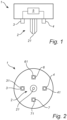
- the 3D printer extruder unit 1 comprises a printing nozzle 2, a first temperature sensor 3, a second temperature sensor 4, and a processing unit 5.
- the printing nozzle 2 is configured for receiving a printing material and depositing said printing material.
- the printing nozzle 2 is provided with a nozzle opening 21 allowing printing material to be deposited through the said nozzle opening 21.
- a filament is received by the 3D printer extruder unit 1 and heated up, the heated-up filament is passed through the printing nozzle 2 and deposited onto a collector plate (not shown) via the nozzle opening 21.
- the first temperature sensor 3 is arranged near the printing nozzle 2 and configured for measuring the first temperature of printing material deposited by the extruder unit 1 at a first position.
- the first temperature sensor 3 is an IR sensor configured for measuring the temperature of material deposited by the printing nozzle 2.
- the second temperature sensor 4 is arranged near the printing nozzle 2 and configured for measuring a second temperature of printing material deposited by the extruder unit 1 at a second position.
- the second temperature sensor 4 is an IR sensor configured for measuring the temperature of material deposited by the printing nozzle 2.
- the processing unit 5 is communicatively connected to the first temperature sensor 3 and the second temperature sensor 4.
- the processing unit 5 is configured to receive sensor data from the first temperature sensor 3 and the second temperature sensor 4.
- the sensor data received by processing unit 5 comprises the first temperature and the second temperature measured by the first temperature sensor 3 and the second temperature sensor 4, respectively.
- the processing unit 5 is configured to compare the received sensor data to a predefined threshold data.
- the predefined threshold data may be a predetermined predefined threshold data.
- the predefined threshold data may comprise pre-recorded sensor data from an approved previous printing process performed by the 3D printer extruder unit 1.
- the processing unit 5 is further configured to generate, based on the comparison between the sensor data and the predefined threshold data, one or more of an alert and a control instruction for controlling one or more printing parameters of a 3D printer.
- the processing unit 5 may further be configured to modulate a controlled temperature of the 3D printer in which the 3D printer extruder unit is mounted 1.
- the processing unit 5 may modulate the controlled temperature with different amplitudes and frequencies, such as an amplitude of 0.1 °C - 5 °C and a frequency of 0.1 Hz - 10 Hz.
- the processing unit 5 may further be configured to compare the sensor data to the modulation of the controlled temperature to estimate a noise level of the sensor data.
- the 3D printer extruder unit 1 comprises a first temperature sensor 3 arranged near the printing nozzle 2 and configured for measuring a first temperature of printing material deposited by the printing nozzle 2 at a first position.
- the 3D printer extruder unit 1 further comprises a second temperature sensor 4 arranged near the printing nozzle 2 and configured for measuring a second temperature of printing material deposited by the printing nozzle 2 at a second position.
- the 3D printer extruder unit 1 further comprises a third temperature sensor 6 arranged near the printing nozzle 2 and configured for measuring a third temperature of printing material deposited by the printing nozzle 2 at a third position.
- the 3D printer extruder unit 1 further comprises a fourth temperature sensor 7 arranged near the printing nozzle 2 and configured for measuring a fourth temperature of printing material deposited by the printing nozzle 2 at a fourth position.
- the first, second, third, and fourth temperature sensor 3, 4, 6, and 7 each comprise an associated cold shield 31, 41, 61, 71 for shielding away stray IR radiation from the first, second, third, fourth temperature sensor 3, 4, 6, and 7.
- the first temperature sensor 3, the second temperature sensor 4, the third temperature sensor 6, and the fourth temperature sensor 7 are arranged symmetrically relative to each other around the printing nozzle 2.
- One or more of the cold shields 31, 41, 61, 71 may be omitted.
- a 3D printing extruder unit according to the invention with another number of temperature sensors than two or four, such as e.g. three temperature sensors or five or more temperature sensors. It is noted that one or more of the first, second, third, and fourth temperature sensor 3, 4, 6, and 7 may also be arranged at or adjacent to the printing nozzle 2.
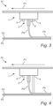
- the 3D printer 10 comprises a 3D printer extruder unit 1.
- the 3D printer extruder unit 1 comprises a first temperature sensor 3 located in a position downstream of the nozzle opening 21 during a 3D printing process such as to enable collecting sensor data indicative of a temperature of the latest deposited layer P3 completed by the 3D printer extruder unit 1.
- the 3D printer extruder unit 1 comprises a second temperature sensor 4 located in a position upstream of the nozzle opening 21 during a 3D printing process such as to enable collecting sensor data indicative of a temperature of a layer P4 while the layer P4 is being deposited by the 3D printer extruder unit 1.
- the 3D printer extruder unit 1 is moved in a printing direction P1 while depositing printing layers P2, P3, and P4.
- the first sensor 3 is arranged in front of the printing nozzle 21 while the 3D printer extruder unit 1 is moved along the printing direction P1
- the second sensor 4 is arranged behind the printing nozzle 21 while the 3D printer extruder unit 1 is moved along the printing direction P1.
- the first temperature sensor 3 and the second temperature sensor 4 are both non-contact temperature sensors configured for measuring the temperature of deposited material from a distance.
- the first sensor 3 may thus measure the temperature of the printing layer P3.
- the second sensor may thus measure the temperature of the freshly deposited printing layer P4, or the temperature of the printing material P5 shortly after leaving the printing nozzle 21.
- the 3D printer extruder unit 1 comprises four temperature sensors (cf. Fig. 2 ), the first sensor 3 may e.g. measure the temperature of the printing layer P3.
- the second sensor may e.g. measure the temperature of the freshly deposited printing layer P4.
- the third temperature sensor 6 may e.g. measure the temperature of the printing material P5 shortly after leaving the printing nozzle 21, i.e. the printing material that has just exited the nozzle opening and that is forming the freshly deposited printing layer P4.
- the third temperature sensor 6 or any other sensor for that matter may need to be configured such that the field of view of the sensor sufficiently focuses or overlap the printing material P5 shortly after leaving the printing nozzle 21, in order to measure its (P5) temperature.
- the fourth temperature sensor 7 may e.g. measure the temperature of a previously deposited printing layer P2 below the printing layer P3.
- the relative position of the temperature sensor with respect to the printing nozzle may be used to measure various temperatures of the printing or printed material, which are of interest in determining the quality of the printing process or the product.
- a schematic cross-sectional view of a 3D printer 10 is shown.
- the 3D printer 10 differs from the one shown in Fig. 3 in that the second temperature sensor 4 is a contact temperature sensor configured for measuring the temperature of deposited material by contacting it.
- the second temperature sensor 4 being a contact temperature sensor such as a brush/slide temperature sensor.
- a contact force applied to the second sensor 4 to provide contact between the second sensor 4 and the 3D printing material is chosen to be smaller than a force determined to deform the 3D printing material.
Landscapes
- Chemical & Material Sciences (AREA)
- Engineering & Computer Science (AREA)
- Materials Engineering (AREA)
- Manufacturing & Machinery (AREA)
- Physics & Mathematics (AREA)
- Mechanical Engineering (AREA)
- Optics & Photonics (AREA)
Claims (14)
- 3D-Drucker-Extrudereinheit (1) für einen 3D-Drucker, umfassend:eine Druckdüse (2), die zum Empfangen eines Druckmaterials und zum Auftragen des Druckmaterials konfiguriert ist, die Druckdüse (2) umfassend eine Düsenöffnung (21),einen ersten Temperatursensor (3), der an oder in der Nähe der Druckdüse angeordnet und zum Messen einer ersten Temperatur von Druckmaterial, das durch die Druckdüse an einer ersten Position aufgetragen wird, konfiguriert ist,einen zweiten Temperatursensor (4), der an oder in der Nähe der Druckdüse angeordnet und zum Messen einer zweiten Temperatur von Druckmaterial, das durch die Druckdüse an einer zweiten Position aufgetragen wird, konfiguriert ist, und wobei die erste Position von der zweiten Position verschieden ist, undeine Verarbeitungseinheit (5), die mit dem ersten Temperatursensor (3) und dem zweiten Temperatursensor (4) kommunikativ verbunden und konfiguriert ist zum:- Empfangen von Sensordaten von dem ersten Temperatursensor und dem zweiten Temperatursensor, wobei die Sensordaten die erste Temperatur und die zweite Temperatur umfassen,- Vergleichen der Sensordaten mit vordefinierten Schwellenwertdaten, und- Erzeugen, basierend auf dem Vergleich zwischen den Sensordaten und den vordefinierten Schwellenwertdaten, eines oder mehrerer Alarme und einer Steueranweisung zum Steuern eines oder mehrerer Druckparameter eines 3D-Druckers,wobei die 3D-Drucker-Extrudereinheit dadurch gekennzeichnet ist, dass, während eines 3D-Druckvorgangs, der erste Temperatursensor (3) sich in einer Position stromabwärts der Düsenöffnung (21) befindet, um so ein Sammeln von Sensordaten zu ermöglichen, die eine Temperatur der zuletzt aufgetragenen Schicht (P3; P2), die durch die 3D-Drucker-Extrudereinheit (1) fertiggestellt wird, anzeigen, und der zweite Temperatursensor (4) sich in einer Position stromaufwärts der Düsenöffnung (21) befindet, um so das Sammeln von Sensordaten zu ermöglichen, die eine Temperatur einer Schicht (P4; P5) anzeigen, während die Schicht (P4; P5) durch die 3D-Drucker-Extrudereinheit (1) gerade aufgetragen wird oder bereits aufgetragen ist.
- 3D-Drucker-Extrudereinheit nach Anspruch 1, wobei die vordefinierten Schwellendaten vorab aufgezeichnete Sensordaten aus einem genehmigten vorherigen Druckvorgang umfassen, der durch den 3D-Drucker durchgeführt wird.
- 3D-Drucker-Extrudereinheit nach Anspruch 1 oder 2, wobei der erste Temperatursensor (3) und/oder der zweite Temperatursensor (4) IR-Sensoren sind.
- 3D-Drucker-Extrudereinheit nach Anspruch 3, wobei der erste Temperatursensor (3) und/oder der zweite Temperatursensor (4) einen Kälteschild (31, 41) zum Abschirmen von Streu-IR-Strahlung umfasst.
- 3D-Drucker-Extrudereinheit nach einem der vorstehenden Ansprüche, wobei die Verarbeitungseinheit (5) konfiguriert ist zum:Regulieren einer gesteuerten Temperatur des 3D-Druckers, undVergleichen der Sensordaten mit der Regulierung der gesteuerten Temperatur, um einen Rauschpegel abzuschätzen und/oder ein Signal-RauschVerhältnis der Sensordaten zu verbessern.
- 3D-Drucker-Extrudereinheit nach Anspruch 5, wobei die gesteuerte Temperatur mit einer Amplitude von 0,1 Grad Celsius - 5 Grad Celsius und einer Frequenz von 0,1 Hz - 10 Hz reguliert wird.
- 3D-Drucker-Extrudereinheit nach einem der vorstehenden Ansprüche, wobei der erste Temperatursensor (3) und/oder der zweite Temperatursensor (4) Kontakttemperatursensoren sind.
- 3D-Drucker-Extrudereinheit nach einem der Ansprüche 1 bis 7, wobei mindestens einer des ersten und des zweiten Temperatursensors (3, 4) aus der Gruppe ausgewählt sind, umfassend berührungslose Temperatursensoren, Thermosäulen, Kontakttemperatursensoren und Bürsten-/Gleittemperatursensoren.
- 3D-Drucker-Extrudereinheit nach einem der Ansprüche 1 bis 7, wobei mindestens einer des ersten und des zweiten Temperatursensors (3, 4) aus der Gruppe ausgewählt sind, umfassend Kontakttemperatursensoren und Bürsten-/Gleittemperatursensoren, und wobei eine Kontaktkraft, die auf mindestens einen des ersten und des zweiten Sensors ausgeübt wird, um einen Kontakt zwischen dem jeweiligen Sensor und dem 3D-Druckmaterial bereitzustellen, kleiner gewählt ist als eine Kraft, die bestimmt ist, um das 3D-Druckmaterial zu verformen.
- 3D-Drucker-Extrudereinheit nach einem der oben genannten Ansprüche, wobei die Druckdüse (2) eine Düsenöffnung (21) umfasst und wobei sich der erste und der zweite Temperatursensor (3, 4) an einer Position an oder in der Nähe der Düsenöffnung befinden.
- 3D-Drucker-Extrudereinheit nach einem der oben genannten Ansprüche, wobei die Druckdüse (2) eine Düsenöffnung (21) umfasst und wobei sich mindestens einer des ersten und des zweiten Temperatursensors (3, 4) innerhalb von 2 cm von der Düsenöffnung befindet.
- 3D-Drucker-Extrudereinheit nach einem der vorstehenden Ansprüche, ferner umfassend:einen dritten Temperatursensor (6), der an oder in der Nähe der Druckdüse (2) angeordnet und zum Messen einer dritten Temperatur von Druckmaterial, das durch die Druckdüse an einer dritten Position aufgetragen wird, konfiguriert ist, und wobei die dritte Position von der ersten Position und der zweiten Position verschieden ist,einen vierten Temperatursensor (7), der an oder in der Nähe der Druckdüse (2) angeordnet und zum Messen einer vierten Temperatur von Druckmaterial, das durch die Druckdüse an einer vierten Position aufgetragen wird, konfiguriert ist, und wobei die vierte Position von der ersten Position, der zweiten Position und der dritten Position verschieden ist,und wobei der erste Temperatursensor (3), der zweite Temperatursensor (4), der dritte Temperatursensor (6) und der vierte Temperatursensor (7) relativ zueinander um die Druckdüse herum symmetrisch angeordnet sind.
- 3D-Drucker-Extrudereinheit nach einem der oben genannten Ansprüche, wobei die Verarbeitungseinheit (5) konfiguriert ist, um die Sensordaten mit vordefinierten Schwellenwertdaten zu vergleichen, durch Interpretieren der Sensordaten, um Temperaturdaten bereitzustellen, und die Temperaturdaten mit vordefinierten Temperaturschwellendaten zu vergleichen.
- 3D-Drucker, umfassend eine 3D-Drucker-Extrudereinheit (1) nach einem der oben genannten Ansprüche.
Applications Claiming Priority (3)
| Application Number | Priority Date | Filing Date | Title |
|---|---|---|---|
| US202163236322P | 2021-08-24 | 2021-08-24 | |
| EP21194127 | 2021-08-31 | ||
| PCT/EP2022/073266 WO2023025698A1 (en) | 2021-08-24 | 2022-08-22 | 3d printer |
Publications (2)
| Publication Number | Publication Date |
|---|---|
| EP4392233A1 EP4392233A1 (de) | 2024-07-03 |
| EP4392233B1 true EP4392233B1 (de) | 2025-03-05 |
Family
ID=83271624
Family Applications (1)
| Application Number | Title | Priority Date | Filing Date |
|---|---|---|---|
| EP22768376.0A Active EP4392233B1 (de) | 2021-08-24 | 2022-08-22 | 3d-drucker |
Country Status (3)
| Country | Link |
|---|---|
| US (1) | US20250187271A1 (de) |
| EP (1) | EP4392233B1 (de) |
| WO (1) | WO2023025698A1 (de) |
Family Cites Families (10)
| Publication number | Priority date | Publication date | Assignee | Title |
|---|---|---|---|---|
| JP6342912B2 (ja) * | 2012-11-08 | 2018-06-13 | ディーディーエム システムズ, インコーポレイテッド | 金属構成要素の加法的製造および修復 |
| FR3034691A1 (fr) * | 2015-04-07 | 2016-10-14 | Soc Eder | Dispositif d'impression en trois dimensions utilisant des dispositifs inductifs et resistifs |
| US10265911B1 (en) | 2015-05-13 | 2019-04-23 | Marvell International Ltd. | Image-based monitoring and feedback system for three-dimensional printing |
| US20170239891A1 (en) * | 2016-02-18 | 2017-08-24 | Velo3D, Inc. | Accurate three-dimensional printing |
| US11207834B2 (en) * | 2016-06-27 | 2021-12-28 | Sciperio, Inc | Selective laser sintered fused deposition printing |
| EP3363562A1 (de) * | 2017-02-16 | 2018-08-22 | Siemens Aktiengesellschaft | Verbesserte additive fertigung |
| GR1009361B (el) * | 2017-05-11 | 2018-09-17 | Κωνσταντινος Ηλια Θεοδοσοπουλος | Συστημα παραγωγης μεσω τρισδιαστατης εκτυπωσης, δισκιων, κοκκιων και καψουλων |
| US11020822B2 (en) * | 2017-08-10 | 2021-06-01 | Formalloy Technologies, Inc. | Active cooling of additive manufacturing process |
| US20210170682A1 (en) * | 2019-12-10 | 2021-06-10 | The Boeing Company | Methods and systems for increasing layer-to-layer bond strength |
| JP7428065B2 (ja) * | 2020-04-27 | 2024-02-06 | セイコーエプソン株式会社 | 三次元造形装置、及び、三次元造形物の製造方法 |
-
2022
- 2022-08-22 EP EP22768376.0A patent/EP4392233B1/de active Active
- 2022-08-22 WO PCT/EP2022/073266 patent/WO2023025698A1/en not_active Ceased
- 2022-08-22 US US18/686,275 patent/US20250187271A1/en active Pending
Also Published As
| Publication number | Publication date |
|---|---|
| US20250187271A1 (en) | 2025-06-12 |
| EP4392233A1 (de) | 2024-07-03 |
| WO2023025698A1 (en) | 2023-03-02 |
Similar Documents
| Publication | Publication Date | Title |
|---|---|---|
| US10981225B2 (en) | Method and device for manufacturing a three-dimensional object | |
| EP3119176B1 (de) | Qualitätsmanagementvorrichtung, qualitätsmanagementverfahren und programm | |
| US9764415B2 (en) | Height control and deposition measurement for the electron beam free form fabrication (EBF3) process | |
| US20170217104A1 (en) | Controlling heating of a surface | |
| EP3312009A1 (de) | Verfahren und system zur thermographischen inspektion von generativ gefertigten teilen | |
| EP3002109A1 (de) | Vorrichtung und verfahren zur prüfung von dreidimensionalem druck | |
| CN106794630B (zh) | 对用于生成三维物体的装置中的温度进行控制 | |
| CN108349005A (zh) | 用于增材制造过程和设备的机器控制 | |
| US20190061267A1 (en) | Thermal imaging device calibration | |
| CN113172240A (zh) | 基于选择性激光熔化的3d打印系统及方法 | |
| JP2019142184A (ja) | 付加造形体の製造システムおよび付加造形体の製造方法 | |
| KR102621920B1 (ko) | 시트의 두께 측정 및 이물질 검출장치 및 그 방법 | |
| US20210339495A1 (en) | Wood material panel hot press and method for operating a wood material panel hot press | |
| EP4392233B1 (de) | 3d-drucker | |
| US20170266886A1 (en) | Camera-based determining of roughness for additively manufactured components | |
| CN120347994B (zh) | 一种熔融沉积3d打印故障监测方法及3d打印设备 | |
| CN117836122A (zh) | 3d打印机 | |
| CA3037819C (en) | Wood material panel pressing device and method for operating a wood material panel pressing device | |
| Khandpur et al. | Development of a low-cost monitoring system for open 3 d printing | |
| US20220048113A1 (en) | Heat source calibration | |
| Imran et al. | In-situ process monitoring and defects detection based on geometrical topography with streaming point cloud processing in directed energy deposition | |
| Andrea et al. | In process monitoring of geometrical characteristics in laser metal deposition: A comparative study | |
| Binder et al. | Linking thermal images with 3D models for FFF printing | |
| EP3250365A1 (de) | Drucktotbereichsidentifizierung | |
| CN120355909A (zh) | 用于处理来自纺织机的输出中的织物的数字图像的方法 |
Legal Events
| Date | Code | Title | Description |
|---|---|---|---|
| STAA | Information on the status of an ep patent application or granted ep patent |
Free format text: STATUS: UNKNOWN |
|
| STAA | Information on the status of an ep patent application or granted ep patent |
Free format text: STATUS: THE INTERNATIONAL PUBLICATION HAS BEEN MADE |
|
| PUAI | Public reference made under article 153(3) epc to a published international application that has entered the european phase |
Free format text: ORIGINAL CODE: 0009012 |
|
| STAA | Information on the status of an ep patent application or granted ep patent |
Free format text: STATUS: REQUEST FOR EXAMINATION WAS MADE |
|
| 17P | Request for examination filed |
Effective date: 20240325 |
|
| AK | Designated contracting states |
Kind code of ref document: A1 Designated state(s): AL AT BE BG CH CY CZ DE DK EE ES FI FR GB GR HR HU IE IS IT LI LT LU LV MC MK MT NL NO PL PT RO RS SE SI SK SM TR |
|
| GRAP | Despatch of communication of intention to grant a patent |
Free format text: ORIGINAL CODE: EPIDOSNIGR1 |
|
| STAA | Information on the status of an ep patent application or granted ep patent |
Free format text: STATUS: GRANT OF PATENT IS INTENDED |
|
| INTG | Intention to grant announced |
Effective date: 20240927 |
|
| DAV | Request for validation of the european patent (deleted) | ||
| DAX | Request for extension of the european patent (deleted) | ||
| P01 | Opt-out of the competence of the unified patent court (upc) registered |
Free format text: CASE NUMBER: APP_61234/2024 Effective date: 20241114 |
|
| GRAS | Grant fee paid |
Free format text: ORIGINAL CODE: EPIDOSNIGR3 |
|
| GRAA | (expected) grant |
Free format text: ORIGINAL CODE: 0009210 |
|
| STAA | Information on the status of an ep patent application or granted ep patent |
Free format text: STATUS: THE PATENT HAS BEEN GRANTED |
|
| AK | Designated contracting states |
Kind code of ref document: B1 Designated state(s): AL AT BE BG CH CY CZ DE DK EE ES FI FR GB GR HR HU IE IS IT LI LT LU LV MC MK MT NL NO PL PT RO RS SE SI SK SM TR |
|
| REG | Reference to a national code |
Ref country code: GB Ref legal event code: FG4D |
|
| REG | Reference to a national code |
Ref country code: CH Ref legal event code: EP |
|
| REG | Reference to a national code |
Ref country code: IE Ref legal event code: FG4D |
|
| REG | Reference to a national code |
Ref country code: DE Ref legal event code: R096 Ref document number: 602022011518 Country of ref document: DE |
|
| PG25 | Lapsed in a contracting state [announced via postgrant information from national office to epo] |
Ref country code: RS Free format text: LAPSE BECAUSE OF FAILURE TO SUBMIT A TRANSLATION OF THE DESCRIPTION OR TO PAY THE FEE WITHIN THE PRESCRIBED TIME-LIMIT Effective date: 20250605 |
|
| PG25 | Lapsed in a contracting state [announced via postgrant information from national office to epo] |
Ref country code: FI Free format text: LAPSE BECAUSE OF FAILURE TO SUBMIT A TRANSLATION OF THE DESCRIPTION OR TO PAY THE FEE WITHIN THE PRESCRIBED TIME-LIMIT Effective date: 20250305 |
|
| REG | Reference to a national code |
Ref country code: NL Ref legal event code: MP Effective date: 20250305 |
|
| PG25 | Lapsed in a contracting state [announced via postgrant information from national office to epo] |
Ref country code: ES Free format text: LAPSE BECAUSE OF FAILURE TO SUBMIT A TRANSLATION OF THE DESCRIPTION OR TO PAY THE FEE WITHIN THE PRESCRIBED TIME-LIMIT Effective date: 20250305 |
|
| REG | Reference to a national code |
Ref country code: LT Ref legal event code: MG9D |
|
| PG25 | Lapsed in a contracting state [announced via postgrant information from national office to epo] |
Ref country code: NO Free format text: LAPSE BECAUSE OF FAILURE TO SUBMIT A TRANSLATION OF THE DESCRIPTION OR TO PAY THE FEE WITHIN THE PRESCRIBED TIME-LIMIT Effective date: 20250605 |
|
| PG25 | Lapsed in a contracting state [announced via postgrant information from national office to epo] |
Ref country code: HR Free format text: LAPSE BECAUSE OF FAILURE TO SUBMIT A TRANSLATION OF THE DESCRIPTION OR TO PAY THE FEE WITHIN THE PRESCRIBED TIME-LIMIT Effective date: 20250305 |
|
| PG25 | Lapsed in a contracting state [announced via postgrant information from national office to epo] |
Ref country code: LV Free format text: LAPSE BECAUSE OF FAILURE TO SUBMIT A TRANSLATION OF THE DESCRIPTION OR TO PAY THE FEE WITHIN THE PRESCRIBED TIME-LIMIT Effective date: 20250305 |
|
| PG25 | Lapsed in a contracting state [announced via postgrant information from national office to epo] |
Ref country code: GR Free format text: LAPSE BECAUSE OF FAILURE TO SUBMIT A TRANSLATION OF THE DESCRIPTION OR TO PAY THE FEE WITHIN THE PRESCRIBED TIME-LIMIT Effective date: 20250606 Ref country code: BG Free format text: LAPSE BECAUSE OF FAILURE TO SUBMIT A TRANSLATION OF THE DESCRIPTION OR TO PAY THE FEE WITHIN THE PRESCRIBED TIME-LIMIT Effective date: 20250305 |
|
| PG25 | Lapsed in a contracting state [announced via postgrant information from national office to epo] |
Ref country code: NL Free format text: LAPSE BECAUSE OF FAILURE TO SUBMIT A TRANSLATION OF THE DESCRIPTION OR TO PAY THE FEE WITHIN THE PRESCRIBED TIME-LIMIT Effective date: 20250305 |
|
| PG25 | Lapsed in a contracting state [announced via postgrant information from national office to epo] |
Ref country code: SE Free format text: LAPSE BECAUSE OF FAILURE TO SUBMIT A TRANSLATION OF THE DESCRIPTION OR TO PAY THE FEE WITHIN THE PRESCRIBED TIME-LIMIT Effective date: 20250305 |
|
| PG25 | Lapsed in a contracting state [announced via postgrant information from national office to epo] |
Ref country code: SM Free format text: LAPSE BECAUSE OF FAILURE TO SUBMIT A TRANSLATION OF THE DESCRIPTION OR TO PAY THE FEE WITHIN THE PRESCRIBED TIME-LIMIT Effective date: 20250305 |
|
| PG25 | Lapsed in a contracting state [announced via postgrant information from national office to epo] |
Ref country code: PT Free format text: LAPSE BECAUSE OF FAILURE TO SUBMIT A TRANSLATION OF THE DESCRIPTION OR TO PAY THE FEE WITHIN THE PRESCRIBED TIME-LIMIT Effective date: 20250707 |
|
| PG25 | Lapsed in a contracting state [announced via postgrant information from national office to epo] |
Ref country code: PL Free format text: LAPSE BECAUSE OF FAILURE TO SUBMIT A TRANSLATION OF THE DESCRIPTION OR TO PAY THE FEE WITHIN THE PRESCRIBED TIME-LIMIT Effective date: 20250305 Ref country code: IT Free format text: LAPSE BECAUSE OF FAILURE TO SUBMIT A TRANSLATION OF THE DESCRIPTION OR TO PAY THE FEE WITHIN THE PRESCRIBED TIME-LIMIT Effective date: 20250305 |
|
| PG25 | Lapsed in a contracting state [announced via postgrant information from national office to epo] |
Ref country code: AT Free format text: LAPSE BECAUSE OF FAILURE TO SUBMIT A TRANSLATION OF THE DESCRIPTION OR TO PAY THE FEE WITHIN THE PRESCRIBED TIME-LIMIT Effective date: 20250305 |
|
| PGFP | Annual fee paid to national office [announced via postgrant information from national office to epo] |
Ref country code: FR Payment date: 20250825 Year of fee payment: 4 |
|
| PG25 | Lapsed in a contracting state [announced via postgrant information from national office to epo] |
Ref country code: EE Free format text: LAPSE BECAUSE OF FAILURE TO SUBMIT A TRANSLATION OF THE DESCRIPTION OR TO PAY THE FEE WITHIN THE PRESCRIBED TIME-LIMIT Effective date: 20250305 Ref country code: CZ Free format text: LAPSE BECAUSE OF FAILURE TO SUBMIT A TRANSLATION OF THE DESCRIPTION OR TO PAY THE FEE WITHIN THE PRESCRIBED TIME-LIMIT Effective date: 20250305 |
|
| PG25 | Lapsed in a contracting state [announced via postgrant information from national office to epo] |
Ref country code: RO Free format text: LAPSE BECAUSE OF FAILURE TO SUBMIT A TRANSLATION OF THE DESCRIPTION OR TO PAY THE FEE WITHIN THE PRESCRIBED TIME-LIMIT Effective date: 20250305 |
|
| PG25 | Lapsed in a contracting state [announced via postgrant information from national office to epo] |
Ref country code: SK Free format text: LAPSE BECAUSE OF FAILURE TO SUBMIT A TRANSLATION OF THE DESCRIPTION OR TO PAY THE FEE WITHIN THE PRESCRIBED TIME-LIMIT Effective date: 20250305 |
|
| PG25 | Lapsed in a contracting state [announced via postgrant information from national office to epo] |
Ref country code: IS Free format text: LAPSE BECAUSE OF FAILURE TO SUBMIT A TRANSLATION OF THE DESCRIPTION OR TO PAY THE FEE WITHIN THE PRESCRIBED TIME-LIMIT Effective date: 20250705 |
|
| REG | Reference to a national code |
Ref country code: DE Ref legal event code: R097 Ref document number: 602022011518 Country of ref document: DE |
|
| PGFP | Annual fee paid to national office [announced via postgrant information from national office to epo] |
Ref country code: DE Payment date: 20251028 Year of fee payment: 4 |
|
| PLBE | No opposition filed within time limit |
Free format text: ORIGINAL CODE: 0009261 |
|
| STAA | Information on the status of an ep patent application or granted ep patent |
Free format text: STATUS: NO OPPOSITION FILED WITHIN TIME LIMIT |
|
| PG25 | Lapsed in a contracting state [announced via postgrant information from national office to epo] |
Ref country code: DK Free format text: LAPSE BECAUSE OF FAILURE TO SUBMIT A TRANSLATION OF THE DESCRIPTION OR TO PAY THE FEE WITHIN THE PRESCRIBED TIME-LIMIT Effective date: 20250305 |
|
| REG | Reference to a national code |
Ref country code: CH Ref legal event code: L10 Free format text: ST27 STATUS EVENT CODE: U-0-0-L10-L00 (AS PROVIDED BY THE NATIONAL OFFICE) Effective date: 20260114 |
|
| 26N | No opposition filed |
Effective date: 20251208 |