EP4391210A1 - Intermodular busbar including insulating layer and battery pack including same - Google Patents
Intermodular busbar including insulating layer and battery pack including same Download PDFInfo
- Publication number
- EP4391210A1 EP4391210A1 EP23863363.0A EP23863363A EP4391210A1 EP 4391210 A1 EP4391210 A1 EP 4391210A1 EP 23863363 A EP23863363 A EP 23863363A EP 4391210 A1 EP4391210 A1 EP 4391210A1
- Authority
- EP
- European Patent Office
- Prior art keywords
- insulating layer
- inter
- module busbar
- metal plate
- module
- Prior art date
- Legal status (The legal status is an assumption and is not a legal conclusion. Google has not performed a legal analysis and makes no representation as to the accuracy of the status listed.)
- Granted
Links
Images


Classifications
-
- B—PERFORMING OPERATIONS; TRANSPORTING
- B32—LAYERED PRODUCTS
- B32B—LAYERED PRODUCTS, i.e. PRODUCTS BUILT-UP OF STRATA OF FLAT OR NON-FLAT, e.g. CELLULAR OR HONEYCOMB, FORM
- B32B1/00—Layered products having a non-planar shape
- B32B1/08—Tubular products
-
- B—PERFORMING OPERATIONS; TRANSPORTING
- B32—LAYERED PRODUCTS
- B32B—LAYERED PRODUCTS, i.e. PRODUCTS BUILT-UP OF STRATA OF FLAT OR NON-FLAT, e.g. CELLULAR OR HONEYCOMB, FORM
- B32B27/00—Layered products comprising a layer of synthetic resin
- B32B27/06—Layered products comprising a layer of synthetic resin as the main or only constituent of a layer, which is next to another layer of the same or of a different material
- B32B27/08—Layered products comprising a layer of synthetic resin as the main or only constituent of a layer, which is next to another layer of the same or of a different material of synthetic resin
-
- B—PERFORMING OPERATIONS; TRANSPORTING
- B32—LAYERED PRODUCTS
- B32B—LAYERED PRODUCTS, i.e. PRODUCTS BUILT-UP OF STRATA OF FLAT OR NON-FLAT, e.g. CELLULAR OR HONEYCOMB, FORM
- B32B27/00—Layered products comprising a layer of synthetic resin
- B32B27/28—Layered products comprising a layer of synthetic resin comprising synthetic resins not wholly covered by any one of the sub-groups B32B27/30 - B32B27/42
- B32B27/281—Layered products comprising a layer of synthetic resin comprising synthetic resins not wholly covered by any one of the sub-groups B32B27/30 - B32B27/42 comprising polyimides
-
- B—PERFORMING OPERATIONS; TRANSPORTING
- B32—LAYERED PRODUCTS
- B32B—LAYERED PRODUCTS, i.e. PRODUCTS BUILT-UP OF STRATA OF FLAT OR NON-FLAT, e.g. CELLULAR OR HONEYCOMB, FORM
- B32B27/00—Layered products comprising a layer of synthetic resin
- B32B27/28—Layered products comprising a layer of synthetic resin comprising synthetic resins not wholly covered by any one of the sub-groups B32B27/30 - B32B27/42
- B32B27/283—Layered products comprising a layer of synthetic resin comprising synthetic resins not wholly covered by any one of the sub-groups B32B27/30 - B32B27/42 comprising polysiloxanes
-
- B—PERFORMING OPERATIONS; TRANSPORTING
- B32—LAYERED PRODUCTS
- B32B—LAYERED PRODUCTS, i.e. PRODUCTS BUILT-UP OF STRATA OF FLAT OR NON-FLAT, e.g. CELLULAR OR HONEYCOMB, FORM
- B32B27/00—Layered products comprising a layer of synthetic resin
- B32B27/28—Layered products comprising a layer of synthetic resin comprising synthetic resins not wholly covered by any one of the sub-groups B32B27/30 - B32B27/42
- B32B27/286—Layered products comprising a layer of synthetic resin comprising synthetic resins not wholly covered by any one of the sub-groups B32B27/30 - B32B27/42 comprising polysulphones; polysulfides
-
- B—PERFORMING OPERATIONS; TRANSPORTING
- B32—LAYERED PRODUCTS
- B32B—LAYERED PRODUCTS, i.e. PRODUCTS BUILT-UP OF STRATA OF FLAT OR NON-FLAT, e.g. CELLULAR OR HONEYCOMB, FORM
- B32B27/00—Layered products comprising a layer of synthetic resin
- B32B27/28—Layered products comprising a layer of synthetic resin comprising synthetic resins not wholly covered by any one of the sub-groups B32B27/30 - B32B27/42
- B32B27/288—Layered products comprising a layer of synthetic resin comprising synthetic resins not wholly covered by any one of the sub-groups B32B27/30 - B32B27/42 comprising polyketones
-
- B—PERFORMING OPERATIONS; TRANSPORTING
- B32—LAYERED PRODUCTS
- B32B—LAYERED PRODUCTS, i.e. PRODUCTS BUILT-UP OF STRATA OF FLAT OR NON-FLAT, e.g. CELLULAR OR HONEYCOMB, FORM
- B32B27/00—Layered products comprising a layer of synthetic resin
- B32B27/30—Layered products comprising a layer of synthetic resin comprising vinyl (co)polymers; comprising acrylic (co)polymers
- B32B27/308—Layered products comprising a layer of synthetic resin comprising vinyl (co)polymers; comprising acrylic (co)polymers comprising acrylic (co)polymers
-
- B—PERFORMING OPERATIONS; TRANSPORTING
- B32—LAYERED PRODUCTS
- B32B—LAYERED PRODUCTS, i.e. PRODUCTS BUILT-UP OF STRATA OF FLAT OR NON-FLAT, e.g. CELLULAR OR HONEYCOMB, FORM
- B32B27/00—Layered products comprising a layer of synthetic resin
- B32B27/34—Layered products comprising a layer of synthetic resin comprising polyamides
-
- H—ELECTRICITY
- H01—ELECTRIC ELEMENTS
- H01B—CABLES; CONDUCTORS; INSULATORS; SELECTION OF MATERIALS FOR THEIR CONDUCTIVE, INSULATING OR DIELECTRIC PROPERTIES
- H01B7/00—Insulated conductors or cables characterised by their form
- H01B7/17—Protection against damage caused by external factors, e.g. sheaths or armouring
- H01B7/29—Protection against damage caused by extremes of temperature or by flame
- H01B7/295—Protection against damage caused by extremes of temperature or by flame using material resistant to flame
-
- H—ELECTRICITY
- H01—ELECTRIC ELEMENTS
- H01M—PROCESSES OR MEANS, e.g. BATTERIES, FOR THE DIRECT CONVERSION OF CHEMICAL ENERGY INTO ELECTRICAL ENERGY
- H01M50/00—Constructional details or processes of manufacture of the non-active parts of electrochemical cells other than fuel cells, e.g. hybrid cells
- H01M50/20—Mountings; Secondary casings or frames; Racks, modules or packs; Suspension devices; Shock absorbers; Transport or carrying devices; Holders
- H01M50/204—Racks, modules or packs for multiple batteries or multiple cells
-
- H—ELECTRICITY
- H01—ELECTRIC ELEMENTS
- H01M—PROCESSES OR MEANS, e.g. BATTERIES, FOR THE DIRECT CONVERSION OF CHEMICAL ENERGY INTO ELECTRICAL ENERGY
- H01M50/00—Constructional details or processes of manufacture of the non-active parts of electrochemical cells other than fuel cells, e.g. hybrid cells
- H01M50/20—Mountings; Secondary casings or frames; Racks, modules or packs; Suspension devices; Shock absorbers; Transport or carrying devices; Holders
- H01M50/258—Modular batteries; Casings provided with means for assembling
-
- H—ELECTRICITY
- H01—ELECTRIC ELEMENTS
- H01M—PROCESSES OR MEANS, e.g. BATTERIES, FOR THE DIRECT CONVERSION OF CHEMICAL ENERGY INTO ELECTRICAL ENERGY
- H01M50/00—Constructional details or processes of manufacture of the non-active parts of electrochemical cells other than fuel cells, e.g. hybrid cells
- H01M50/50—Current conducting connections for cells or batteries
- H01M50/502—Interconnectors for connecting terminals of adjacent batteries; Interconnectors for connecting cells outside a battery casing
- H01M50/503—Interconnectors for connecting terminals of adjacent batteries; Interconnectors for connecting cells outside a battery casing characterised by the shape of the interconnectors
-
- H—ELECTRICITY
- H01—ELECTRIC ELEMENTS
- H01M—PROCESSES OR MEANS, e.g. BATTERIES, FOR THE DIRECT CONVERSION OF CHEMICAL ENERGY INTO ELECTRICAL ENERGY
- H01M50/00—Constructional details or processes of manufacture of the non-active parts of electrochemical cells other than fuel cells, e.g. hybrid cells
- H01M50/50—Current conducting connections for cells or batteries
- H01M50/502—Interconnectors for connecting terminals of adjacent batteries; Interconnectors for connecting cells outside a battery casing
- H01M50/521—Interconnectors for connecting terminals of adjacent batteries; Interconnectors for connecting cells outside a battery casing characterised by the material
- H01M50/522—Inorganic material
-
- H—ELECTRICITY
- H01—ELECTRIC ELEMENTS
- H01M—PROCESSES OR MEANS, e.g. BATTERIES, FOR THE DIRECT CONVERSION OF CHEMICAL ENERGY INTO ELECTRICAL ENERGY
- H01M50/00—Constructional details or processes of manufacture of the non-active parts of electrochemical cells other than fuel cells, e.g. hybrid cells
- H01M50/50—Current conducting connections for cells or batteries
- H01M50/502—Interconnectors for connecting terminals of adjacent batteries; Interconnectors for connecting cells outside a battery casing
- H01M50/521—Interconnectors for connecting terminals of adjacent batteries; Interconnectors for connecting cells outside a battery casing characterised by the material
- H01M50/524—Organic material
-
- H—ELECTRICITY
- H01—ELECTRIC ELEMENTS
- H01M—PROCESSES OR MEANS, e.g. BATTERIES, FOR THE DIRECT CONVERSION OF CHEMICAL ENERGY INTO ELECTRICAL ENERGY
- H01M50/00—Constructional details or processes of manufacture of the non-active parts of electrochemical cells other than fuel cells, e.g. hybrid cells
- H01M50/50—Current conducting connections for cells or batteries
- H01M50/502—Interconnectors for connecting terminals of adjacent batteries; Interconnectors for connecting cells outside a battery casing
- H01M50/521—Interconnectors for connecting terminals of adjacent batteries; Interconnectors for connecting cells outside a battery casing characterised by the material
- H01M50/526—Interconnectors for connecting terminals of adjacent batteries; Interconnectors for connecting cells outside a battery casing characterised by the material having a layered structure
-
- H—ELECTRICITY
- H01—ELECTRIC ELEMENTS
- H01M—PROCESSES OR MEANS, e.g. BATTERIES, FOR THE DIRECT CONVERSION OF CHEMICAL ENERGY INTO ELECTRICAL ENERGY
- H01M50/00—Constructional details or processes of manufacture of the non-active parts of electrochemical cells other than fuel cells, e.g. hybrid cells
- H01M50/50—Current conducting connections for cells or batteries
- H01M50/572—Means for preventing undesired use or discharge
- H01M50/584—Means for preventing undesired use or discharge for preventing incorrect connections inside or outside the batteries
- H01M50/588—Means for preventing undesired use or discharge for preventing incorrect connections inside or outside the batteries outside the batteries, e.g. incorrect connections of terminals or busbars
-
- H—ELECTRICITY
- H01—ELECTRIC ELEMENTS
- H01M—PROCESSES OR MEANS, e.g. BATTERIES, FOR THE DIRECT CONVERSION OF CHEMICAL ENERGY INTO ELECTRICAL ENERGY
- H01M50/00—Constructional details or processes of manufacture of the non-active parts of electrochemical cells other than fuel cells, e.g. hybrid cells
- H01M50/50—Current conducting connections for cells or batteries
- H01M50/572—Means for preventing undesired use or discharge
- H01M50/584—Means for preventing undesired use or discharge for preventing incorrect connections inside or outside the batteries
- H01M50/59—Means for preventing undesired use or discharge for preventing incorrect connections inside or outside the batteries characterised by the protection means
-
- H—ELECTRICITY
- H01—ELECTRIC ELEMENTS
- H01M—PROCESSES OR MEANS, e.g. BATTERIES, FOR THE DIRECT CONVERSION OF CHEMICAL ENERGY INTO ELECTRICAL ENERGY
- H01M50/00—Constructional details or processes of manufacture of the non-active parts of electrochemical cells other than fuel cells, e.g. hybrid cells
- H01M50/50—Current conducting connections for cells or batteries
- H01M50/572—Means for preventing undesired use or discharge
- H01M50/584—Means for preventing undesired use or discharge for preventing incorrect connections inside or outside the batteries
- H01M50/59—Means for preventing undesired use or discharge for preventing incorrect connections inside or outside the batteries characterised by the protection means
- H01M50/591—Covers
-
- Y—GENERAL TAGGING OF NEW TECHNOLOGICAL DEVELOPMENTS; GENERAL TAGGING OF CROSS-SECTIONAL TECHNOLOGIES SPANNING OVER SEVERAL SECTIONS OF THE IPC; TECHNICAL SUBJECTS COVERED BY FORMER USPC CROSS-REFERENCE ART COLLECTIONS [XRACs] AND DIGESTS
- Y02—TECHNOLOGIES OR APPLICATIONS FOR MITIGATION OR ADAPTATION AGAINST CLIMATE CHANGE
- Y02E—REDUCTION OF GREENHOUSE GAS [GHG] EMISSIONS, RELATED TO ENERGY GENERATION, TRANSMISSION OR DISTRIBUTION
- Y02E60/00—Enabling technologies; Technologies with a potential or indirect contribution to GHG emissions mitigation
- Y02E60/10—Energy storage using batteries
Definitions
- the present invention relates to an inter-module busbar including an insulating layer and a battery pack including the same. More particularly, the present invention relates to an inter-module busbar configured such that an insulated state of the inter-module busbar is maintained even when fire breaks out in a battery pack, whereby it is possible to prevent short circuit even when in contact with a peripheral portion, and a battery pack including the same.
- a lithium secondary battery which has high energy density per weight, is being used as an energy source not only for mobile devices, such as a cellular phone, a tablet, a Bluetooth earphone, and an electronic cigarette, but also for medium and large-sized devices, such as an electric bicycle, an electric kickboard, and electric vehicles.
- an inter-module busbar is widely used as a means for electrical connection between battery cells in the battery module and a means for electrical connection between battery modules in the battery pack.
- the inter-module busbar is useful as a large current conduction means since the inter-module busbar is capable of allowing large current to stably flow therethrough even with a relatively small thickness compared to a cable.
- the inter-module busbar may be used in a form in which a metal plate including copper or aluminum having excellent electrical conductivity is disposed inside and the remaining part of the outer surface of the metal plate, excluding opposite ends of the metal plate at which coupling is performed to secure electrical insulation, is covered with a tube or an injection-molded product.
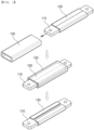
- FIG. 1 is a perspective view showing a conventional inter-module busbar before and after damage by fire.
- FIG. 1 shows the structure of the inter-module busbar and the state in which the inter-module busbar is damaged by fire.
- the conventional inter-module busbar includes a metal plate 110 made of an electrically conductive material, an insulating tape 120 configured to enclose the remaining part of an outer surface of the metal plate 110 excluding opposite ends thereof, and a silicone tube 130 added to an outer surface of the insulating tape 120.
- Each of the insulating tape 120 and the silicone tube 130 is made of an electrically insulating material, and therefore it is possible to secure insulation of configurations of the inter-module busbar other than a device coupled to opposite ends of the inter-module busbar.
- the insulation tape 120 may open up, whereby the metal plate 110 inside may be exposed.
- short circuit When the exposed metal plate comes into contact with a structure of the battery pack, short circuit may occur, and such internal short circuit may form an electrical closed circuit in the battery pack, which may accelerate thermal runaway in the battery pack.
- Patent Document 1 discloses a busbar including a metal bar made of a metal material, an insulative tube configured to cover the remaining part of the metal bar excluding opposite ends thereof, a fireproof tape configured to enclose the metal bar in the insulative tube, and a bandage member made of a fire-resistant material and interposed between the insulative tube and the fireproof tape, the bandage member being configured to fix the fireproof tape to the metal bar in a state of enclosing the fireproof tape.
- the fireproof tape is strongly fixed by the bandage member even though the insulative tube is burned away by fire, whereby it is possible to prevent the metal bar from directly contacting a surrounding metal object and thus to prevent short circuit.
- Patent Document 2 discloses a busbar including a metal bar made of a metal material, a bandage member configured to enclose the remaining part of the metal bar excluding opposite ends thereof, and an insulative tube configured to enclose both the metal bar and the bandage member.
- the bandage member on the surface of the metal bar remains attached to the surface of the metal bar even in the event of fire, whereby the metal bar does not directly contact a surrounding metal object, and therefore it is possible to prevent short circuit.
- each of the busbars of Patent Document 1 and Patent Document 2 further includes a bandage member, whereby the thickness and weight of the busbar may be increased.
- an inter-module busbar configured such that an increase in volume and weight of the inter-module busbar is minimized while exposure of a metal material inside is prevented even though an insulating material added to an outer surface of the busbar is burned away by fire.
- the present invention has been made in view of the above problems, and it is an object of the present invention to provide an inter-module busbar configured such that a metal plate inside is not exposed even though a second insulating layer, which is an outer surface, is ceramized and cracked in the event of fire, whereby it is possible to prevent short circuit caused by contact with a surrounding metal object.
- An inter-module busbar to accomplish the above object includes a metal plate for electrical connection, a first insulating layer configured to enclose at least a part of the metal plate, the first insulating layer being expandable at high temperatures, and a second insulating layer added to the first insulating layer, the second insulating layer being configured to be ceramized at high temperatures.
- the first insulating layer may include expandable flame-retardant silicone.
- the second insulating layer may include at least one selected from the group consisting of highly heat-resistant silicone, polyphenylene sulfide, polyetheretherketone, polyphthalamide, polyamide, polysulfone, polyethersulfone, polyetherimide, acrylic fiber, and polybenzimidazole.
- the second insulating layer may be ceramized at a temperature of at least 1,200°C.
- the first insulating layer may expand and may be inserted into the cracks to fill spaces in the cracks.
- the metal plate in the first insulating layer and the second insulating layer may not be exposed.
- the first insulating layer and the second insulating layer may not be added to opposite ends of the metal plate, and the metal plate may be exposed to constitute an electrical connection portion.
- the electrical connection portion may be provided with at least one opening for connection.
- the present invention provides a battery pack including battery modules electrically connected using the inter-module busbar.
- the battery pack may include a battery pack housing configured to receive two or more battery modules, a pack frame configured to allow the battery modules to be disposed in spaces partitioned therein in order to position the battery modules, and an inter-module busbar configured to electrically connect the battery modules to each other, wherein the inter-module busbar may be disposed such that a first insulating layer and a second insulating layer are located at an upper surface of the pack frame, and electrical connection portions provided at opposite ends of the inter-module busbar to which the first insulating layer and the second insulating layer are not added may be coupled to connectors of the battery modules.
- the insulated state of the inter-module busbar may be maintained while the metal plate is not exposed in the state in which the inter-module busbar is in contact with the pack frame.
- the present invention may provide various combinations of the above solving means.
- an inter-module busbar according to the present invention is configured such that, even though a second insulating layer is ceramized and cracked in the event of fire, a first insulation layer, which is expandable at high temperatures, penetrates into the cracks in the second insulation layer and fills gaps therein, whereby it is possible to prevent a metal plate from being exposed.
- An inter-module busbar according to the present invention is a type of busbar used as an electrical connection means, and refers to a means configured to interconnect battery modules disposed in a battery pack.
- the shape of the inter-module busbar may be configured in consideration of the positions of connectors of the battery modules, and the inter-module busbar may have various shapes, such as a shape in which the inter-module busbar is bent upwards or downwards so as to be parallel to the overall width, an L-shape in which the inter-module busbar is bent by 90 degrees in the plane, a [-shape in which the inter-module busbar is bent at opposite ends thereof in the plane, and a ⁇ -shape.
- each of the opposite ends of the inter-module busbar is usually used as a connection portion for coupling to an external device, a structure for connection, such as a fastening hole for bolt fastening, is provided.
- FIG. 2 is a plan view and a vertical sectional view of an inter-module busbar according to the present invention, wherein a section taken along A-A in the plan view at an upper part of FIG. 2 is shown as a vertical sectional view at a lower part of FIG. 2 .
- the inter-module busbar 200 includes a metal plate 210 for electrical connection, a first insulating layer 220 configured to enclose at least a part of the metal plate 210, the first insulating layer being expandable at high temperatures, and a second insulating layer 230 added to the first insulating layer 220, the second insulating layer being configured to be ceramized at high temperatures.
- the first insulating layer 220 and the second insulating layer 230 are not added to opposite ends of the metal plate 210, and the ends of the metal plate 210 are exposed to constitute electrical connection portions 240.
- At least one opening 241 for connection is formed in each of the electrical connection portions 240.
- One of the electrical connection portions 240 formed at the opposite ends of the inter-module busbar 200 may be connected to a positive electrode connector of a first battery module, and the other may be connected to a negative electrode connector of a second battery module.
- the bolts may be inserted into the openings 241 and the nuts may be fastened to the bolts, whereby the inter-module busbar 200 may be connected to the first battery module and the second battery module.
- the second insulating layer 230 constitutes the outermost surface with which flames come into direct contact in the event of fire, and therefore the second insulating layer may include at least one selected from the group consisting of highly heat-resistant silicone, polyphenylene sulfide, polyetheretherketone, polyphthalamide, polyamide, polysulfone, polyethersulfone, polyetherimide, acrylic fiber, and polybenzimidazole.
- the second insulating layer 230 may be highly heat-resistant silicone which is ceramized and in which small cracks are formed when exposed to flames or high-temperature gases.
- the highly heat-resistant silicone exhibits the performance of a general silicone resin at room temperature, but at high temperatures, the structure of the highly heat-resistant silicone is changed to a ceramized structure, whereby the highly heat-resistant silicone has ceramic properties, and therefore the highly heat-resistant silicone may withstand impact while maintaining certain strength.
- the second insulating layer 230 may be made of a material that is ceramized at high temperatures, and may be ceramized, for example, at 1,200°C or higher.
- the shape of the second insulating layer may be maintained and the second insulating layer may exhibit flame resistance below 1,200°C.
- the second insulating layer may be ceramized and cracked at 1,200°C or higher.
- the second insulating layer may be ceramized by gas or flames discharged from the battery cell, but the shape of the second insulating layer may be maintained.
- the first insulating layer 220 may include expandable flame-retardant silicone that is expandable at high temperatures.
- the thermal expansion temperature of the first insulating layer 220 may be higher than the temperature at which the second insulating layer 230 is ceramized.
- the second insulating layer is ceramized and cracked.
- the first insulating layer which is expandable at high temperatures, expands and fills gaps between the cracks.
- the metal plate is not exposed to the outside at the parts to the first and second insulating layers of the inter-module busbar are added, and therefore it is possible to secure insulation.
- FIG. 3 is a vertical sectional view showing the inter-module busbar according to the present invention before and after damage by fire.
- FIG. 3 shows three steps of a process in which the inter-module busbar is damaged by fire, wherein time progresses from top to bottom.
- FIG. 3 is a vertical sectional view of a normal inter-module busbar 200 in which no fire breaks out
- an outer surface of the innermost metal plate 210 is sequentially enclosed by the first insulating layer 220, which is expandable at high temperatures, and the second insulating layer 230, which is ceramized at high temperatures.
- the part of the inter-module busbar to which the first insulating layer 220 and the second insulating layer 230 are added may remain enclosed by the first insulating layer 220 and the second insulating layer 230 without communication with the outer surface of the second insulating layer 230.
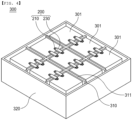
- FIG. 4 is a perspective view of a battery pack including the inter-module busbar of FIG. 2 .
- the battery pack shown in FIG. 4 is configured such that a plurality of battery modules 301 is electrically connected to each other via the inter-module busbar 200 according to the present invention.
- FIG. 4 shows a battery pack including nine battery modules, which is merely an example for illustrative purposes, the arrangement and number of the battery modules constituting the battery pack and the coupling position and shape of the inter-module busbar used to interconnect the battery modules are not limited thereto.
- the battery pack 300 includes a battery pack housing 320 configured to receive two or more battery modules 301, a pack frame 310 configured to allow the battery modules 301 to be disposed in spaces partitioned therein in order to position the battery modules, and an inter-module busbar 200 configured to electrically connect the battery modules 301 to each other, wherein the inter-module busbar 200 is disposed such that a first insulating layer and a second insulating layer 230 are located at an upper surface 311 of the pack frame, and electrical connection portions provided at opposite ends of a metal plate 210 to which the first insulating layer and the second insulating layer 230 are not added are coupled to connectors of the battery modules 301.
- the second insulating layer 230 of the inter-module busbar 200 is disposed in contact with the pack frame 310, as described above, it is possible to secure insulation between the inter-module busbar 200 and the pack frame 310 in a steady state of the battery pack 300 even though the pack frame 310 is made of an electrically conductive metal material.
- inter-module busbar is not disposed at the upper surface of the pack frame 310 and the inter-module busbar is disposed in contact with a component constituting the battery pack and made of an electrically conductive metal material, unlike what is shown in FIG. 4 , insulation between the inter-module busbar and the component made of the electrically conductive metal material may be maintained in the event of fire in the battery pack.
- the first insulating layer and the second insulating layer attached to the metal plate are not burned away and remain added to the outer surface of the metal plate in the event of fire.
- the metal plate since the first insulating layer that has expanded fills cracks formed in the second insulating layer, the metal plate may not be exposed to the outside. Therefore, the inter-module busbar may remain insulated even through the inter-module busbar is in contact with a metal component adjacent thereto.
Landscapes
- Chemical & Material Sciences (AREA)
- Chemical Kinetics & Catalysis (AREA)
- Electrochemistry (AREA)
- General Chemical & Material Sciences (AREA)
- Inorganic Chemistry (AREA)
- Engineering & Computer Science (AREA)
- Mechanical Engineering (AREA)
- Battery Mounting, Suspending (AREA)
- Connection Of Batteries Or Terminals (AREA)
Abstract
Description
- This application claims the benefit of priority to
Korean Patent Application No. 2022-0111786 filed on September 5, 2022 - The present invention relates to an inter-module busbar including an insulating layer and a battery pack including the same. More particularly, the present invention relates to an inter-module busbar configured such that an insulated state of the inter-module busbar is maintained even when fire breaks out in a battery pack, whereby it is possible to prevent short circuit even when in contact with a peripheral portion, and a battery pack including the same.
- There is growing demand for secondary batteries capable of addressing air pollution caused by the use of fossil fuels and storing electrical energy generated from alternative energy. For example, a lithium secondary battery, which has high energy density per weight, is being used as an energy source not only for mobile devices, such as a cellular phone, a tablet, a Bluetooth earphone, and an electronic cigarette, but also for medium and large-sized devices, such as an electric bicycle, an electric kickboard, and electric vehicles.
- As the kinds of devices using the lithium secondary battery as an energy source increase, application of the lithium secondary battery to devices that require high capacity and high power has expanded.
- In line with this trend, there has been an increase in manufacture and use of a battery module, in which a plurality of battery cells is electrically connected to each other, and a battery pack, in which battery modules are connected to each other in series and/or parallel.
- Meanwhile, an inter-module busbar is widely used as a means for electrical connection between battery cells in the battery module and a means for electrical connection between battery modules in the battery pack. The inter-module busbar is useful as a large current conduction means since the inter-module busbar is capable of allowing large current to stably flow therethrough even with a relatively small thickness compared to a cable.
- Generally, the inter-module busbar may be used in a form in which a metal plate including copper or aluminum having excellent electrical conductivity is disposed inside and the remaining part of the outer surface of the metal plate, excluding opposite ends of the metal plate at which coupling is performed to secure electrical insulation, is covered with a tube or an injection-molded product.
- In connection therewith,
FIG. 1 is a perspective view showing a conventional inter-module busbar before and after damage by fire. - An inter-module busbar is used for electrical connection between battery modules, and
FIG. 1 shows the structure of the inter-module busbar and the state in which the inter-module busbar is damaged by fire. - Referring to
FIG. 1 , the conventional inter-module busbar includes ametal plate 110 made of an electrically conductive material, aninsulating tape 120 configured to enclose the remaining part of an outer surface of themetal plate 110 excluding opposite ends thereof, and asilicone tube 130 added to an outer surface of theinsulating tape 120. - Each of the
insulating tape 120 and thesilicone tube 130 is made of an electrically insulating material, and therefore it is possible to secure insulation of configurations of the inter-module busbar other than a device coupled to opposite ends of the inter-module busbar. - When a battery cell in a battery pack ignites or explodes, thermal energy of the battery cell is transferred to neighboring cells, causing fire. When the
silicone tube 130 of the inter-module busbar, which connects battery modules to each other, is damaged by fire in the battery cell, theinsulation tape 120 may open up, whereby themetal plate 110 inside may be exposed. - When the exposed metal plate comes into contact with a structure of the battery pack, short circuit may occur, and such internal short circuit may form an electrical closed circuit in the battery pack, which may accelerate thermal runaway in the battery pack.
- In connection therewith, Patent Document 1 discloses a busbar including a metal bar made of a metal material, an insulative tube configured to cover the remaining part of the metal bar excluding opposite ends thereof, a fireproof tape configured to enclose the metal bar in the insulative tube, and a bandage member made of a fire-resistant material and interposed between the insulative tube and the fireproof tape, the bandage member being configured to fix the fireproof tape to the metal bar in a state of enclosing the fireproof tape.
- In Patent Document 1, the fireproof tape is strongly fixed by the bandage member even though the insulative tube is burned away by fire, whereby it is possible to prevent the metal bar from directly contacting a surrounding metal object and thus to prevent short circuit.
- Patent Document 2 discloses a busbar including a metal bar made of a metal material, a bandage member configured to enclose the remaining part of the metal bar excluding opposite ends thereof, and an insulative tube configured to enclose both the metal bar and the bandage member.
- In Patent Document 2, the bandage member on the surface of the metal bar remains attached to the surface of the metal bar even in the event of fire, whereby the metal bar does not directly contact a surrounding metal object, and therefore it is possible to prevent short circuit.
- However, each of the busbars of Patent Document 1 and Patent Document 2 further includes a bandage member, whereby the thickness and weight of the busbar may be increased.
- Therefore, there is a need for an inter-module busbar configured such that an increase in volume and weight of the inter-module busbar is minimized while exposure of a metal material inside is prevented even though an insulating material added to an outer surface of the busbar is burned away by fire.
-
- (Patent Document 1)
Korean Patent Application Publication No. 2021-0050983 2021.05.10 - (Patent Document 2)
Korean Patent Application Publication No. 2021-0141095 (2021.11.23 - The present invention has been made in view of the above problems, and it is an object of the present invention to provide an inter-module busbar configured such that a metal plate inside is not exposed even though a second insulating layer, which is an outer surface, is ceramized and cracked in the event of fire, whereby it is possible to prevent short circuit caused by contact with a surrounding metal object.
- An inter-module busbar according to the present invention to accomplish the above object includes a metal plate for electrical connection, a first insulating layer configured to enclose at least a part of the metal plate, the first insulating layer being expandable at high temperatures, and a second insulating layer added to the first insulating layer, the second insulating layer being configured to be ceramized at high temperatures.
- The first insulating layer may include expandable flame-retardant silicone.
- The second insulating layer may include at least one selected from the group consisting of highly heat-resistant silicone, polyphenylene sulfide, polyetheretherketone, polyphthalamide, polyamide, polysulfone, polyethersulfone, polyetherimide, acrylic fiber, and polybenzimidazole.
- The second insulating layer may be ceramized at a temperature of at least 1,200°C.
- When the second insulating layer is ceramized and cracks are formed in the second insulating layer due to an increase in temperature, the first insulating layer may expand and may be inserted into the cracks to fill spaces in the cracks.
- When the first insulating layer expands, the metal plate in the first insulating layer and the second insulating layer may not be exposed.
- The first insulating layer and the second insulating layer may not be added to opposite ends of the metal plate, and the metal plate may be exposed to constitute an electrical connection portion.
- The electrical connection portion may be provided with at least one opening for connection.
- The present invention provides a battery pack including battery modules electrically connected using the inter-module busbar.
- The battery pack may include a battery pack housing configured to receive two or more battery modules, a pack frame configured to allow the battery modules to be disposed in spaces partitioned therein in order to position the battery modules, and an inter-module busbar configured to electrically connect the battery modules to each other, wherein the inter-module busbar may be disposed such that a first insulating layer and a second insulating layer are located at an upper surface of the pack frame, and electrical connection portions provided at opposite ends of the inter-module busbar to which the first insulating layer and the second insulating layer are not added may be coupled to connectors of the battery modules.
- When the second insulating layer is ceramized and the first insulating layer expands due to an increase in temperature of the pack frame, the insulated state of the inter-module busbar may be maintained while the metal plate is not exposed in the state in which the inter-module busbar is in contact with the pack frame.
- In addition, the present invention may provide various combinations of the above solving means.
- As is apparent from the above description, an inter-module busbar according to the present invention is configured such that, even though a second insulating layer is ceramized and cracked in the event of fire, a first insulation layer, which is expandable at high temperatures, penetrates into the cracks in the second insulation layer and fills gaps therein, whereby it is possible to prevent a metal plate from being exposed.
- In the event of fire, therefore, it is possible to secure insulation of the busbar even though the busbar remains in contact with a surrounding metal object.
-
-
FIG. 1 is a perspective view showing a conventional inter-module busbar before and after damage by fire. -
FIG. 2 is a plan view and a vertical sectional view of an inter-module busbar according to the present invention. -
FIG. 3 is a vertical sectional view showing the inter-module busbar according to the present invention before and after damage by fire. -
FIG. 4 is a perspective view of a battery pack including the inter-module busbar ofFIG. 2 . - Now, preferred embodiments of the present invention will be described in detail with reference to the accompanying drawings such that the preferred embodiments of the present invention can be easily implemented by a person having ordinary skill in the art to which the present invention pertains. In describing the principle of operation of the preferred embodiments of the present invention in detail, however, a detailed description of known functions and configurations incorporated herein will be omitted when the same may obscure the subject matter of the present invention.
- In addition, the same reference numbers will be used throughout the drawings to refer to parts that perform similar functions or operations. In the case in which one part is said to be connected to another part throughout the specification, not only may the one part be directly connected to the other part, but also, the one part may be indirectly connected to the other part via a further part. In addition, that a certain element is included does not mean that other elements are excluded, but means that such elements may be further included unless mentioned otherwise.
- In addition, a description to embody elements through limitation or addition may be applied to all inventions, unless particularly restricted, and does not limit a specific invention.
- Also, in the description of the invention and the claims of the present application, singular forms are intended to include plural forms unless mentioned otherwise.
- Also, in the description of the invention and the claims of the present application, "or" includes "and" unless mentioned otherwise. Therefore, "including A or B" means three cases, namely, the case including A, the case including B, and the case including A and B.
- Hereinafter, embodiments of the present invention will be described in detail with reference to the drawings.
- An inter-module busbar according to the present invention is a type of busbar used as an electrical connection means, and refers to a means configured to interconnect battery modules disposed in a battery pack.
- Consequently, it is possible to set the length of the inter-module busbar in consideration of the distance between battery modules to be connected and to set the width and thickness of the inter-module busbar in consideration of the amount of current that passes through the inter-module busbar and the resistance of the inter-module busbar.
- In addition, the shape of the inter-module busbar may be configured in consideration of the positions of connectors of the battery modules, and the inter-module busbar may have various shapes, such as a shape in which the inter-module busbar is bent upwards or downwards so as to be parallel to the overall width, an L-shape in which the inter-module busbar is bent by 90 degrees in the plane, a [-shape in which the inter-module busbar is bent at opposite ends thereof in the plane, and a └┐-shape.
- Since each of the opposite ends of the inter-module busbar is usually used as a connection portion for coupling to an external device, a structure for connection, such as a fastening hole for bolt fastening, is provided.
-
FIG. 2 is a plan view and a vertical sectional view of an inter-module busbar according to the present invention, wherein a section taken along A-A in the plan view at an upper part ofFIG. 2 is shown as a vertical sectional view at a lower part ofFIG. 2 . - Referring to
FIG. 2 , theinter-module busbar 200 includes ametal plate 210 for electrical connection, a first insulatinglayer 220 configured to enclose at least a part of themetal plate 210, the first insulating layer being expandable at high temperatures, and a second insulatinglayer 230 added to the first insulatinglayer 220, the second insulating layer being configured to be ceramized at high temperatures. - The first insulating
layer 220 and the second insulatinglayer 230 are not added to opposite ends of themetal plate 210, and the ends of themetal plate 210 are exposed to constituteelectrical connection portions 240. - At least one
opening 241 for connection is formed in each of theelectrical connection portions 240. - One of the
electrical connection portions 240 formed at the opposite ends of theinter-module busbar 200 may be connected to a positive electrode connector of a first battery module, and the other may be connected to a negative electrode connector of a second battery module. Specifically, when a bolting operation utilizing bolts and nuts is performed such that the inter-module busbar is connected to the connectors of the battery modules, the bolts may be inserted into theopenings 241 and the nuts may be fastened to the bolts, whereby theinter-module busbar 200 may be connected to the first battery module and the second battery module. - The second
insulating layer 230 constitutes the outermost surface with which flames come into direct contact in the event of fire, and therefore the second insulating layer may include at least one selected from the group consisting of highly heat-resistant silicone, polyphenylene sulfide, polyetheretherketone, polyphthalamide, polyamide, polysulfone, polyethersulfone, polyetherimide, acrylic fiber, and polybenzimidazole. - Specifically, the second insulating
layer 230 may be highly heat-resistant silicone which is ceramized and in which small cracks are formed when exposed to flames or high-temperature gases. - The highly heat-resistant silicone exhibits the performance of a general silicone resin at room temperature, but at high temperatures, the structure of the highly heat-resistant silicone is changed to a ceramized structure, whereby the highly heat-resistant silicone has ceramic properties, and therefore the highly heat-resistant silicone may withstand impact while maintaining certain strength.
- The second
insulating layer 230 may be made of a material that is ceramized at high temperatures, and may be ceramized, for example, at 1,200°C or higher. - Consequently, the shape of the second insulating layer may be maintained and the second insulating layer may exhibit flame resistance below 1,200°C. However, the second insulating layer may be ceramized and cracked at 1,200°C or higher.
- When a battery cell in a battery pack ignites and explodes and heat is transferred to the inter-module busbar coupled to the battery modules, the second insulating layer may be ceramized by gas or flames discharged from the battery cell, but the shape of the second insulating layer may be maintained.
- Consequently, it is possible to prevent a conventional problem in which, when a silicone tube is added to an outer surface of a metal plate, the silicone tube is burned away, whereby the metal plate is exposed.
- The first insulating
layer 220 may include expandable flame-retardant silicone that is expandable at high temperatures. - The thermal expansion temperature of the first insulating
layer 220 may be higher than the temperature at which the second insulatinglayer 230 is ceramized. - That is, when a high-temperature environment is formed due to fire, the second insulating layer is ceramized and cracked. When flames or venting gases penetrate through the cracks and come into contact with the first insulating layer, the first insulating layer, which is expandable at high temperatures, expands and fills gaps between the cracks. As described above, the metal plate is not exposed to the outside at the parts to the first and second insulating layers of the inter-module busbar are added, and therefore it is possible to secure insulation.
-
FIG. 3 is a vertical sectional view showing the inter-module busbar according to the present invention before and after damage by fire. -
FIG. 3 shows three steps of a process in which the inter-module busbar is damaged by fire, wherein time progresses from top to bottom. - Referring to the first figure of
FIG. 3 , which is a vertical sectional view of a normalinter-module busbar 200 in which no fire breaks out, an outer surface of theinnermost metal plate 210 is sequentially enclosed by the first insulatinglayer 220, which is expandable at high temperatures, and the second insulatinglayer 230, which is ceramized at high temperatures. - Referring to the second figure of
FIG. 3 , when fire breaks out in the battery cell, flames or high-temperature gases are transferred to the inter-module busbar, whereby the second insulatinglayer 230, which is the outermost layer, is ceramized and cracked, and the first insulatinglayer 220 and the outside of the second insulatinglayer 230 communicate with each other through the cracks. - Referring to the third figure of
FIG. 3 , when the second insulatinglayer 230 is ceramized and cracked when the temperature increases, high-temperature gases and flames are transferred to the first insulatinglayer 220 through the cracks, whereby the first insulatinglayer 220 expands and is inserted into the cracks to fill spaces in the cracks. - Since the first insulating
layer 220 expands to fill the gaps in the cracks formed in the second insulatinglayer 230, as described above, the part of the inter-module busbar to which the first insulatinglayer 220 and the second insulatinglayer 230 are added may remain enclosed by the first insulatinglayer 220 and the second insulatinglayer 230 without communication with the outer surface of the second insulatinglayer 230. - When the second insulating layer is ceramized by fire and the first insulating layer expands, therefore, the part of the metal plate in the first insulating layer and the second insulating layer is not exposed.
-
FIG. 4 is a perspective view of a battery pack including the inter-module busbar ofFIG. 2 . - The battery pack shown in
FIG. 4 is configured such that a plurality ofbattery modules 301 is electrically connected to each other via theinter-module busbar 200 according to the present invention. AlthoughFIG. 4 shows a battery pack including nine battery modules, which is merely an example for illustrative purposes, the arrangement and number of the battery modules constituting the battery pack and the coupling position and shape of the inter-module busbar used to interconnect the battery modules are not limited thereto. - Referring to
FIG. 4 , the battery pack 300 according to the present invention includes abattery pack housing 320 configured to receive two ormore battery modules 301, apack frame 310 configured to allow thebattery modules 301 to be disposed in spaces partitioned therein in order to position the battery modules, and aninter-module busbar 200 configured to electrically connect thebattery modules 301 to each other, wherein theinter-module busbar 200 is disposed such that a first insulating layer and a second insulatinglayer 230 are located at anupper surface 311 of the pack frame, and electrical connection portions provided at opposite ends of ametal plate 210 to which the first insulating layer and the second insulatinglayer 230 are not added are coupled to connectors of thebattery modules 301. - Since the second insulating
layer 230 of theinter-module busbar 200 is disposed in contact with thepack frame 310, as described above, it is possible to secure insulation between theinter-module busbar 200 and thepack frame 310 in a steady state of the battery pack 300 even though thepack frame 310 is made of an electrically conductive metal material. - However, when flames or high-temperature gases are discharged from battery cells constituting the battery pack 300, whereby the temperature of the
pack frame 310 increases, the second insulatinglayer 230 is ceramized, and the first insulatinglayer 220 expands, insulation of theinter-module busbar 200 may be maintained even in the state in which the inter-module busbar is in contact with thepack frame 310. - Meanwhile, even when the inter-module busbar is not disposed at the upper surface of the
pack frame 310 and the inter-module busbar is disposed in contact with a component constituting the battery pack and made of an electrically conductive metal material, unlike what is shown inFIG. 4 , insulation between the inter-module busbar and the component made of the electrically conductive metal material may be maintained in the event of fire in the battery pack. - In the present invention, as described above, the first insulating layer and the second insulating layer attached to the metal plate are not burned away and remain added to the outer surface of the metal plate in the event of fire. In addition, since the first insulating layer that has expanded fills cracks formed in the second insulating layer, the metal plate may not be exposed to the outside. Therefore, the inter-module busbar may remain insulated even through the inter-module busbar is in contact with a metal component adjacent thereto.
- Those skilled in the art to which the present invention pertains will appreciate that various applications and modifications are possible within the category of the present invention based on the above description.
-
- 110, 210:
- Metal plates
- 120:
- Insulating tape
- 130:
- Silicone tube
- 200:
- Inter-module busbar
- 220:
- First insulating layer
- 230:
- Second insulating layer
- 240:
- Electrical connection portion
- 241:
- Opening
- 300:
- Battery pack
- 301:
- Battery module
- 310:
- Pack frame
- 311:
- Upper surface of pack frame
- 320:
- Battery pack housing
Claims (11)
- An inter-module busbar comprising:a metal plate for electrical connection;a first insulating layer configured to enclose at least a part of the metal plate, the first insulating layer being expandable at high temperatures; anda second insulating layer added to the first insulating layer, the second insulating layer being configured to be ceramized at high temperatures.
- The inter-module busbar according to claim 1, wherein the first insulating layer comprises expandable flame-retardant silicone.
- The inter-module busbar according to claim 1, wherein the second insulating layer comprises at least one selected from a group consisting of highly heat-resistant silicone, polyphenylene sulfide, polyetheretherketone, polyphthalamide, polyamide, polysulfone, polyethersulfone, polyetherimide, acrylic fiber, and polybenzimidazole.
- The inter-module busbar according to claim 3, wherein the second insulating layer is ceramized at a temperature of at least 1,200°C.
- The inter-module busbar according to claim 1, wherein, when the second insulating layer is ceramized and cracks are formed in the second insulating layer due to an increase in temperature, the first insulating layer expands and is inserted into the cracks to fill spaces in the cracks.
- The inter-module busbar according to claim 4, wherein, when the first insulating layer expands, the metal plate in the first insulating layer and the second insulating layer is not exposed.
- The inter-module busbar according to claim 1, wherein the first insulating layer and the second insulating layer are not added to opposite ends of the metal plate, and the metal plate is exposed to constitute an electrical connection portion.
- The inter-module busbar according to claim 6, wherein the electrical connection portion is provided with at least one opening for connection.
- A battery pack comprising battery modules electrically connected using the inter-module busbar according to any one of claims 1 to 8.
- The battery pack according to claim 9, wherein
the battery pack comprises:a battery pack housing configured to receive two or more battery modules;a pack frame configured to allow the battery modules to be disposed in spaces partitioned therein in order to position the battery modules; andan inter-module busbar configured to electrically connect the battery modules to each other, whereinthe inter-module busbar is disposed such that a first insulating layer and a second insulating layer are located at an upper surface of the pack frame, andelectrical connection portions provided at opposite ends of the inter-module busbar to which the first insulating layer and the second insulating layer are not added are coupled to connectors of the battery modules. - The battery pack according to claim 10, wherein, when the second insulating layer is ceramized and the first insulating layer expands due to an increase in temperature of the pack frame, an insulated state of the inter-module busbar is maintained while the metal plate is not exposed in a state in which the inter-module busbar is in contact with the pack frame.
Applications Claiming Priority (2)
| Application Number | Priority Date | Filing Date | Title |
|---|---|---|---|
| KR1020220111786A KR20240033312A (en) | 2022-09-05 | 2022-09-05 | Inter Module Bus Bar Comprising Insulating Layer and Battery Pack Having the same |
| PCT/KR2023/011965 WO2024053884A1 (en) | 2022-09-05 | 2023-08-11 | Intermodular busbar including insulating layer and battery pack including same |
Publications (3)
| Publication Number | Publication Date |
|---|---|
| EP4391210A1 true EP4391210A1 (en) | 2024-06-26 |
| EP4391210A4 EP4391210A4 (en) | 2025-07-30 |
| EP4391210B1 EP4391210B1 (en) | 2026-04-29 |
Family
ID=90191573
Family Applications (1)
| Application Number | Title | Priority Date | Filing Date |
|---|---|---|---|
| EP23863363.0A Active EP4391210B1 (en) | 2022-09-05 | 2023-08-11 | Intermodular busbar including insulating layer and battery pack including same |
Country Status (6)
| Country | Link |
|---|---|
| US (1) | US20240405381A1 (en) |
| EP (1) | EP4391210B1 (en) |
| JP (1) | JP7712030B2 (en) |
| KR (1) | KR20240033312A (en) |
| CN (1) | CN118044055A (en) |
| WO (1) | WO2024053884A1 (en) |
Cited By (1)
| Publication number | Priority date | Publication date | Assignee | Title |
|---|---|---|---|---|
| EP4443639A4 (en) * | 2022-09-08 | 2026-02-11 | Lg Energy Solution Ltd | Collection rail with improved flame resistance and battery pack so that |
Families Citing this family (2)
| Publication number | Priority date | Publication date | Assignee | Title |
|---|---|---|---|---|
| USD1082698S1 (en) * | 2023-08-08 | 2025-07-08 | The Noco Company | Busbar for a battery |
| JP2026067508A (en) * | 2024-10-09 | 2026-04-21 | 矢崎総業株式会社 | Terminal block structure and terminal block |
Family Cites Families (12)
| Publication number | Priority date | Publication date | Assignee | Title |
|---|---|---|---|---|
| KR101463196B1 (en) * | 2012-01-03 | 2014-11-21 | 주식회사 엘지화학 | Battery pack and Connecting bar applied for battery pack |
| KR102221801B1 (en) * | 2014-02-04 | 2021-03-02 | 삼성에스디아이 주식회사 | Busbar module |
| KR20160049260A (en) * | 2014-10-27 | 2016-05-09 | 엘에스전선 주식회사 | Flexible bus bar |
| US10559805B2 (en) * | 2017-02-01 | 2020-02-11 | GM Global Technology Operations LLC | Battery for an electric vehicle |
| CN107564610A (en) * | 2017-10-20 | 2018-01-09 | 浙江中大元通特种电缆有限公司 | A kind of chain armored fireproofing cable of Ceramic silicon rubber insulating sheath stainless steel |
| KR102946350B1 (en) | 2019-10-29 | 2026-03-30 | 주식회사 엘지에너지솔루션 | Bus-bar with safety against a fire |
| KR102926964B1 (en) | 2020-05-15 | 2026-02-11 | 주식회사 엘지에너지솔루션 | Bus-bar with safety against a fire |
| KR102951289B1 (en) * | 2020-09-28 | 2026-04-09 | 주식회사 엘지에너지솔루션 | Flat Flexible Cable busbar |
| JP7612404B2 (en) * | 2020-12-15 | 2025-01-14 | 日産自動車株式会社 | Vehicle Battery System |
| KR20220111786A (en) | 2021-02-02 | 2022-08-10 | 주식회사 크로스지 | A method of manufacturing a vehicle catalyst device and a vehicle catalyst device manufactured through the method |
| CN214624512U (en) * | 2021-05-13 | 2021-11-05 | 深圳市富程威科技有限公司 | A wrapping tape, a high-voltage connector and a power battery |
| CN215770643U (en) * | 2021-06-23 | 2022-02-08 | 深圳市沃尔热缩有限公司 | Busbar connecting piece |
-
2022
- 2022-09-05 KR KR1020220111786A patent/KR20240033312A/en active Pending
-
2023
- 2023-08-11 US US18/697,289 patent/US20240405381A1/en active Pending
- 2023-08-11 CN CN202380013213.5A patent/CN118044055A/en active Pending
- 2023-08-11 EP EP23863363.0A patent/EP4391210B1/en active Active
- 2023-08-11 JP JP2023580371A patent/JP7712030B2/en active Active
- 2023-08-11 WO PCT/KR2023/011965 patent/WO2024053884A1/en not_active Ceased
Cited By (1)
| Publication number | Priority date | Publication date | Assignee | Title |
|---|---|---|---|---|
| EP4443639A4 (en) * | 2022-09-08 | 2026-02-11 | Lg Energy Solution Ltd | Collection rail with improved flame resistance and battery pack so that |
Also Published As
| Publication number | Publication date |
|---|---|
| JP7712030B2 (en) | 2025-07-23 |
| EP4391210B1 (en) | 2026-04-29 |
| JP2024538476A (en) | 2024-10-23 |
| WO2024053884A1 (en) | 2024-03-14 |
| CN118044055A (en) | 2024-05-14 |
| US20240405381A1 (en) | 2024-12-05 |
| KR20240033312A (en) | 2024-03-12 |
| EP4391210A4 (en) | 2025-07-30 |
Similar Documents
| Publication | Publication Date | Title |
|---|---|---|
| KR102732262B1 (en) | Battery Module and Battery Pack Having the same | |
| EP4391210B1 (en) | Intermodular busbar including insulating layer and battery pack including same | |
| EP3176851B1 (en) | Electrical energy storage device | |
| KR102505613B1 (en) | Battery pack | |
| US20230291022A1 (en) | End plate assembly including thermistor, battery module and battery pack including the same | |
| CN111033878A (en) | Battery module and battery pack including the same | |
| KR102920181B1 (en) | Battery Cell Assembly Comprising Blocking Plate and Battery Pack Comprising the Same | |
| US20230073204A1 (en) | Battery pack | |
| EP4443639A1 (en) | Busbar having improved flame resistance, and battery pack including same | |
| CN115911677A (en) | Battery | |
| CN118523034A (en) | Battery device | |
| JP7808197B2 (en) | Busbar assembly including firewall and battery pack including same | |
| KR102872698B1 (en) | Busbar with improved flame resistance and battery pack comprising the same | |
| TWI800095B (en) | Battery module and battery pack | |
| JP7578375B2 (en) | Battery pack and device including same | |
| US20260088195A1 (en) | Wire for Electrical Connection and Battery Module in Which Electrical Connection is Formed Using the Same | |
| CN217468684U (en) | a battery device | |
| KR20240124709A (en) | Battery Device | |
| CN118556342A (en) | Bus bar having improved flame retardancy and battery pack including the same | |
| CN121444265A (en) | Battery modules, battery packs including battery modules, and vehicles including battery packs. | |
| WO2025258769A1 (en) | Battery module cover and battery pack, and vehicle including same | |
| JP2025539081A (en) | Busbar assembly and battery pack including same | |
| KR20240127560A (en) | Battery Device | |
| CN119999003A (en) | Bus bar assembly and battery pack including the same |
Legal Events
| Date | Code | Title | Description |
|---|---|---|---|
| STAA | Information on the status of an ep patent application or granted ep patent |
Free format text: STATUS: THE INTERNATIONAL PUBLICATION HAS BEEN MADE |
|
| PUAI | Public reference made under article 153(3) epc to a published international application that has entered the european phase |
Free format text: ORIGINAL CODE: 0009012 |
|
| STAA | Information on the status of an ep patent application or granted ep patent |
Free format text: STATUS: REQUEST FOR EXAMINATION WAS MADE |
|
| 17P | Request for examination filed |
Effective date: 20240321 |
|
| AK | Designated contracting states |
Kind code of ref document: A1 Designated state(s): AL AT BE BG CH CY CZ DE DK EE ES FI FR GB GR HR HU IE IS IT LI LT LU LV MC ME MK MT NL NO PL PT RO RS SE SI SK SM TR |
|
| A4 | Supplementary search report drawn up and despatched |
Effective date: 20250627 |
|
| RIC1 | Information provided on ipc code assigned before grant |
Ipc: H01M 50/591 20210101AFI20250623BHEP Ipc: H01M 50/503 20210101ALI20250623BHEP Ipc: B32B 27/08 20060101ALI20250623BHEP Ipc: B32B 27/28 20060101ALI20250623BHEP Ipc: B32B 27/34 20060101ALI20250623BHEP Ipc: B32B 27/30 20060101ALI20250623BHEP Ipc: B32B 1/08 20060101ALI20250623BHEP Ipc: H01M 50/526 20210101ALI20250623BHEP Ipc: H01M 50/588 20210101ALI20250623BHEP |
|
| DAV | Request for validation of the european patent (deleted) | ||
| DAX | Request for extension of the european patent (deleted) | ||
| GRAP | Despatch of communication of intention to grant a patent |
Free format text: ORIGINAL CODE: EPIDOSNIGR1 |
|
| STAA | Information on the status of an ep patent application or granted ep patent |
Free format text: STATUS: GRANT OF PATENT IS INTENDED |
|
| RIC1 | Information provided on ipc code assigned before grant |
Ipc: H01M 50/591 20210101AFI20260107BHEP Ipc: H01M 50/503 20210101ALI20260107BHEP Ipc: B32B 27/08 20060101ALI20260107BHEP Ipc: B32B 27/28 20060101ALI20260107BHEP Ipc: B32B 27/34 20060101ALI20260107BHEP Ipc: B32B 27/30 20060101ALI20260107BHEP Ipc: B32B 1/08 20060101ALI20260107BHEP Ipc: H01M 50/526 20210101ALI20260107BHEP Ipc: H01M 50/588 20210101ALI20260107BHEP |
|
| INTG | Intention to grant announced |
Effective date: 20260116 |
|
| GRAS | Grant fee paid |
Free format text: ORIGINAL CODE: EPIDOSNIGR3 |
|
| GRAA | (expected) grant |
Free format text: ORIGINAL CODE: 0009210 |
|
| STAA | Information on the status of an ep patent application or granted ep patent |
Free format text: STATUS: THE PATENT HAS BEEN GRANTED |
|
| P01 | Opt-out of the competence of the unified patent court (upc) registered |
Free format text: CASE NUMBER: UPC_APP_0008760_4391210/2026 Effective date: 20260305 |
|
| AK | Designated contracting states |
Kind code of ref document: B1 Designated state(s): AL AT BE BG CH CY CZ DE DK EE ES FI FR GB GR HR HU IE IS IT LI LT LU LV MC ME MK MT NL NO PL PT RO RS SE SI SK SM TR |
|
| REG | Reference to a national code |
Ref country code: CH Ref legal event code: F10 Free format text: ST27 STATUS EVENT CODE: U-0-0-F10-F00 (AS PROVIDED BY THE NATIONAL OFFICE) Effective date: 20260429 Ref country code: GB Ref legal event code: FG4D |