EP4391203A1 - Battery module - Google Patents
Battery module Download PDFInfo
- Publication number
- EP4391203A1 EP4391203A1 EP22932493.4A EP22932493A EP4391203A1 EP 4391203 A1 EP4391203 A1 EP 4391203A1 EP 22932493 A EP22932493 A EP 22932493A EP 4391203 A1 EP4391203 A1 EP 4391203A1
- Authority
- EP
- European Patent Office
- Prior art keywords
- battery module
- mounting surface
- mounting bracket
- cells
- fpc
- Prior art date
- Legal status (The legal status is an assumption and is not a legal conclusion. Google has not performed a legal analysis and makes no representation as to the accuracy of the status listed.)
- Pending
Links
Images



Classifications
-
- H—ELECTRICITY
- H01—ELECTRIC ELEMENTS
- H01M—PROCESSES OR MEANS, e.g. BATTERIES, FOR THE DIRECT CONVERSION OF CHEMICAL ENERGY INTO ELECTRICAL ENERGY
- H01M50/00—Constructional details or processes of manufacture of the non-active parts of electrochemical cells other than fuel cells, e.g. hybrid cells
- H01M50/20—Mountings; Secondary casings or frames; Racks, modules or packs; Suspension devices; Shock absorbers; Transport or carrying devices; Holders
- H01M50/233—Mountings; Secondary casings or frames; Racks, modules or packs; Suspension devices; Shock absorbers; Transport or carrying devices; Holders characterised by physical properties of casings or racks, e.g. dimensions
- H01M50/242—Mountings; Secondary casings or frames; Racks, modules or packs; Suspension devices; Shock absorbers; Transport or carrying devices; Holders characterised by physical properties of casings or racks, e.g. dimensions adapted for protecting batteries against vibrations, collision impact or swelling
-
- H—ELECTRICITY
- H01—ELECTRIC ELEMENTS
- H01M—PROCESSES OR MEANS, e.g. BATTERIES, FOR THE DIRECT CONVERSION OF CHEMICAL ENERGY INTO ELECTRICAL ENERGY
- H01M10/00—Secondary cells; Manufacture thereof
- H01M10/42—Methods or arrangements for servicing or maintenance of secondary cells or secondary half-cells
- H01M10/425—Structural combination with electronic components, e.g. electronic circuits integrated to the outside of the casing
-
- H—ELECTRICITY
- H01—ELECTRIC ELEMENTS
- H01M—PROCESSES OR MEANS, e.g. BATTERIES, FOR THE DIRECT CONVERSION OF CHEMICAL ENERGY INTO ELECTRICAL ENERGY
- H01M50/00—Constructional details or processes of manufacture of the non-active parts of electrochemical cells other than fuel cells, e.g. hybrid cells
- H01M50/20—Mountings; Secondary casings or frames; Racks, modules or packs; Suspension devices; Shock absorbers; Transport or carrying devices; Holders
- H01M50/204—Racks, modules or packs for multiple batteries or multiple cells
- H01M50/207—Racks, modules or packs for multiple batteries or multiple cells characterised by their shape
- H01M50/209—Racks, modules or packs for multiple batteries or multiple cells characterised by their shape adapted for prismatic or rectangular cells
-
- H—ELECTRICITY
- H01—ELECTRIC ELEMENTS
- H01M—PROCESSES OR MEANS, e.g. BATTERIES, FOR THE DIRECT CONVERSION OF CHEMICAL ENERGY INTO ELECTRICAL ENERGY
- H01M50/00—Constructional details or processes of manufacture of the non-active parts of electrochemical cells other than fuel cells, e.g. hybrid cells
- H01M50/20—Mountings; Secondary casings or frames; Racks, modules or packs; Suspension devices; Shock absorbers; Transport or carrying devices; Holders
- H01M50/204—Racks, modules or packs for multiple batteries or multiple cells
- H01M50/207—Racks, modules or packs for multiple batteries or multiple cells characterised by their shape
- H01M50/213—Racks, modules or packs for multiple batteries or multiple cells characterised by their shape adapted for cells having curved cross-section, e.g. round or elliptic
-
- H—ELECTRICITY
- H01—ELECTRIC ELEMENTS
- H01M—PROCESSES OR MEANS, e.g. BATTERIES, FOR THE DIRECT CONVERSION OF CHEMICAL ENERGY INTO ELECTRICAL ENERGY
- H01M50/00—Constructional details or processes of manufacture of the non-active parts of electrochemical cells other than fuel cells, e.g. hybrid cells
- H01M50/20—Mountings; Secondary casings or frames; Racks, modules or packs; Suspension devices; Shock absorbers; Transport or carrying devices; Holders
- H01M50/244—Secondary casings; Racks; Suspension devices; Carrying devices; Holders characterised by their mounting method
-
- H—ELECTRICITY
- H01—ELECTRIC ELEMENTS
- H01M—PROCESSES OR MEANS, e.g. BATTERIES, FOR THE DIRECT CONVERSION OF CHEMICAL ENERGY INTO ELECTRICAL ENERGY
- H01M50/00—Constructional details or processes of manufacture of the non-active parts of electrochemical cells other than fuel cells, e.g. hybrid cells
- H01M50/20—Mountings; Secondary casings or frames; Racks, modules or packs; Suspension devices; Shock absorbers; Transport or carrying devices; Holders
- H01M50/258—Modular batteries; Casings provided with means for assembling
-
- H—ELECTRICITY
- H01—ELECTRIC ELEMENTS
- H01M—PROCESSES OR MEANS, e.g. BATTERIES, FOR THE DIRECT CONVERSION OF CHEMICAL ENERGY INTO ELECTRICAL ENERGY
- H01M50/00—Constructional details or processes of manufacture of the non-active parts of electrochemical cells other than fuel cells, e.g. hybrid cells
- H01M50/20—Mountings; Secondary casings or frames; Racks, modules or packs; Suspension devices; Shock absorbers; Transport or carrying devices; Holders
- H01M50/262—Mountings; Secondary casings or frames; Racks, modules or packs; Suspension devices; Shock absorbers; Transport or carrying devices; Holders with fastening means, e.g. locks
-
- H—ELECTRICITY
- H01—ELECTRIC ELEMENTS
- H01M—PROCESSES OR MEANS, e.g. BATTERIES, FOR THE DIRECT CONVERSION OF CHEMICAL ENERGY INTO ELECTRICAL ENERGY
- H01M50/00—Constructional details or processes of manufacture of the non-active parts of electrochemical cells other than fuel cells, e.g. hybrid cells
- H01M50/20—Mountings; Secondary casings or frames; Racks, modules or packs; Suspension devices; Shock absorbers; Transport or carrying devices; Holders
- H01M50/284—Mountings; Secondary casings or frames; Racks, modules or packs; Suspension devices; Shock absorbers; Transport or carrying devices; Holders with incorporated circuit boards, e.g. printed circuit boards [PCB]
-
- H—ELECTRICITY
- H01—ELECTRIC ELEMENTS
- H01M—PROCESSES OR MEANS, e.g. BATTERIES, FOR THE DIRECT CONVERSION OF CHEMICAL ENERGY INTO ELECTRICAL ENERGY
- H01M50/00—Constructional details or processes of manufacture of the non-active parts of electrochemical cells other than fuel cells, e.g. hybrid cells
- H01M50/20—Mountings; Secondary casings or frames; Racks, modules or packs; Suspension devices; Shock absorbers; Transport or carrying devices; Holders
- H01M50/289—Mountings; Secondary casings or frames; Racks, modules or packs; Suspension devices; Shock absorbers; Transport or carrying devices; Holders characterised by spacing elements or positioning means within frames, racks or packs
-
- H—ELECTRICITY
- H01—ELECTRIC ELEMENTS
- H01M—PROCESSES OR MEANS, e.g. BATTERIES, FOR THE DIRECT CONVERSION OF CHEMICAL ENERGY INTO ELECTRICAL ENERGY
- H01M50/00—Constructional details or processes of manufacture of the non-active parts of electrochemical cells other than fuel cells, e.g. hybrid cells
- H01M50/50—Current conducting connections for cells or batteries
- H01M50/502—Interconnectors for connecting terminals of adjacent batteries; Interconnectors for connecting cells outside a battery casing
- H01M50/505—Interconnectors for connecting terminals of adjacent batteries; Interconnectors for connecting cells outside a battery casing comprising a single busbar
-
- H—ELECTRICITY
- H01—ELECTRIC ELEMENTS
- H01M—PROCESSES OR MEANS, e.g. BATTERIES, FOR THE DIRECT CONVERSION OF CHEMICAL ENERGY INTO ELECTRICAL ENERGY
- H01M50/00—Constructional details or processes of manufacture of the non-active parts of electrochemical cells other than fuel cells, e.g. hybrid cells
- H01M50/50—Current conducting connections for cells or batteries
- H01M50/502—Interconnectors for connecting terminals of adjacent batteries; Interconnectors for connecting cells outside a battery casing
- H01M50/507—Interconnectors for connecting terminals of adjacent batteries; Interconnectors for connecting cells outside a battery casing comprising an arrangement of two or more busbars within a container structure, e.g. busbar modules
-
- H—ELECTRICITY
- H01—ELECTRIC ELEMENTS
- H01M—PROCESSES OR MEANS, e.g. BATTERIES, FOR THE DIRECT CONVERSION OF CHEMICAL ENERGY INTO ELECTRICAL ENERGY
- H01M50/00—Constructional details or processes of manufacture of the non-active parts of electrochemical cells other than fuel cells, e.g. hybrid cells
- H01M50/50—Current conducting connections for cells or batteries
- H01M50/502—Interconnectors for connecting terminals of adjacent batteries; Interconnectors for connecting cells outside a battery casing
- H01M50/514—Methods for interconnecting adjacent batteries or cells
-
- H—ELECTRICITY
- H01—ELECTRIC ELEMENTS
- H01M—PROCESSES OR MEANS, e.g. BATTERIES, FOR THE DIRECT CONVERSION OF CHEMICAL ENERGY INTO ELECTRICAL ENERGY
- H01M50/00—Constructional details or processes of manufacture of the non-active parts of electrochemical cells other than fuel cells, e.g. hybrid cells
- H01M50/50—Current conducting connections for cells or batteries
- H01M50/502—Interconnectors for connecting terminals of adjacent batteries; Interconnectors for connecting cells outside a battery casing
- H01M50/519—Interconnectors for connecting terminals of adjacent batteries; Interconnectors for connecting cells outside a battery casing comprising printed circuit boards [PCB]
-
- H—ELECTRICITY
- H05—ELECTRIC TECHNIQUES NOT OTHERWISE PROVIDED FOR
- H05K—PRINTED CIRCUITS; CASINGS OR CONSTRUCTIONAL DETAILS OF ELECTRIC APPARATUS; MANUFACTURE OF ASSEMBLAGES OF ELECTRICAL COMPONENTS
- H05K1/00—Printed circuits
- H05K1/02—Details
- H05K1/0213—Electrical arrangements not otherwise provided for
- H05K1/0263—High current adaptations, e.g. printed high current conductors or using auxiliary non-printed means; Fine and coarse circuit patterns on one circuit board
-
- H—ELECTRICITY
- H05—ELECTRIC TECHNIQUES NOT OTHERWISE PROVIDED FOR
- H05K—PRINTED CIRCUITS; CASINGS OR CONSTRUCTIONAL DETAILS OF ELECTRIC APPARATUS; MANUFACTURE OF ASSEMBLAGES OF ELECTRICAL COMPONENTS
- H05K1/00—Printed circuits
- H05K1/18—Printed circuits structurally associated with non-printed electric components
- H05K1/189—Printed circuits structurally associated with non-printed electric components characterised by the use of flexible or folded printed circuits
-
- H—ELECTRICITY
- H05—ELECTRIC TECHNIQUES NOT OTHERWISE PROVIDED FOR
- H05K—PRINTED CIRCUITS; CASINGS OR CONSTRUCTIONAL DETAILS OF ELECTRIC APPARATUS; MANUFACTURE OF ASSEMBLAGES OF ELECTRICAL COMPONENTS
- H05K1/00—Printed circuits
- H05K1/02—Details
- H05K1/0277—Bendability or stretchability details
- H05K1/028—Bending or folding regions of flexible printed circuits
- H05K1/0281—Reinforcement details thereof
-
- H—ELECTRICITY
- H05—ELECTRIC TECHNIQUES NOT OTHERWISE PROVIDED FOR
- H05K—PRINTED CIRCUITS; CASINGS OR CONSTRUCTIONAL DETAILS OF ELECTRIC APPARATUS; MANUFACTURE OF ASSEMBLAGES OF ELECTRICAL COMPONENTS
- H05K2201/00—Indexing scheme relating to printed circuits covered by H05K1/00
- H05K2201/10—Details of components or other objects attached to or integrated in a printed circuit board
- H05K2201/10007—Types of components
- H05K2201/10037—Printed or non-printed battery
-
- Y—GENERAL TAGGING OF NEW TECHNOLOGICAL DEVELOPMENTS; GENERAL TAGGING OF CROSS-SECTIONAL TECHNOLOGIES SPANNING OVER SEVERAL SECTIONS OF THE IPC; TECHNICAL SUBJECTS COVERED BY FORMER USPC CROSS-REFERENCE ART COLLECTIONS [XRACs] AND DIGESTS
- Y02—TECHNOLOGIES OR APPLICATIONS FOR MITIGATION OR ADAPTATION AGAINST CLIMATE CHANGE
- Y02E—REDUCTION OF GREENHOUSE GAS [GHG] EMISSIONS, RELATED TO ENERGY GENERATION, TRANSMISSION OR DISTRIBUTION
- Y02E60/00—Enabling technologies; Technologies with a potential or indirect contribution to GHG emissions mitigation
- Y02E60/10—Energy storage using batteries
Definitions
- the present application relates to the field of battery technologies, and for example to a battery module.
- the smallest unit of a power battery is a cell.
- One power battery includes hundreds of individual cells, where a group of cells may form a battery module, and a plurality of battery modules may form the power battery.
- the battery module is generally provided with a mounting bracket, and assembling of the battery module includes fixing structural members such as cells, an Flexible Printed Circuit (FPC) board, an acquisition wiring harness, a connector, and a busbar to the mounting bracket. If these structural members are all separately fed, it will result in an increase in the types of materials, an increase in the difficulty of material management and control, and an impact on assembly efficiency and product quality at an assembling station of the battery module.
- FPC Flexible Printed Circuit
- the connector is generally installed in a manner of snap connection for the battery module in the related art and fixed to the mounting bracket by the snap. Since the snap is easily loosened and vibration of the battery module in use may cause the connector to shake, resulting in a poor acquisition contact and affecting reliability of the battery module.
- the present application provides a battery module capable of realizing integrated feeding at a cell assembling station, and reliable riveting connection between a connector and a mounting bracket, thereby improving assembly efficiency and assembly quality and ensuring work reliability.
- the present application provides a battery module, including:
- the FPC board assembly further includes a reinforcing plate connected to a side of the connection end away from the connector and riveted to the fixing plate.
- the fixing plate is provided with a plurality of riveting posts
- the reinforcing plate and the connection end both are provided with a plurality of positioning holes through which the riveting posts can pass and be riveted to the reinforcing plate and the connection end.
- the mounting bracket further includes a plurality of reinforcing ribs each connected to a side of the fixing plate away from the connection end.
- the busbar assembly includes a negative output busbar, where the negative output busbar includes a bent output end parallel to an axial direction of the cell and configured to connect an adjacent battery module.
- the bent output end is attached to the mounting bracket and provided with a connection bolt, an axial direction of the connection bolt is perpendicular to a side surface of the mounting bracket, and the connection bolt is configured to connect the adjacent battery module and screwed to a mounting hole of the bent output end.
- the plurality of FPC boards include a first FPC board embedded among the plurality of cells and a second FPC board disposed around an outer periphery of the cells.
- the first FPC board includes a bent extension portion capable of attaching a side of the plurality of cells.
- the mounting bracket includes a plurality of first limiting members protruded on the first mounting surface and configured to snap-fit the cells.
- the mounting bracket includes a plurality of second limiting members protruded on the second mounting surface and configured to snap-fit the busbar assembly.
- the FPC boards are vertically arranged on the first mounting surface, and thus the FPC boards do not affect the assembling of the cells, so that the busbar assembly, the mounting bracket, and the FPC board assembly can be pre-assembled in advance.
- the busbar assembly, the mounting bracket, and the FPC board assembly are assembled in a preceding working procedure, so that the integrated feeding is realized, the types of the materials are reduced, difficulty of the material management and control is reduced, the occupation of equipment and a field is reduced, and the assembly efficiency and the product quality are improved.
- connection end of the FPC board is fixedly connected to the connector and riveted to the fixing plate, so that the installation of the connector is realized, the manufacturing process is simple, the processing cost is low, the fixing is reliable, the looseness does not occur, even the vibration of the battery module in use is difficult to cause the vibration of the connector, the poor acquisition contact is avoided, and the working reliability of the battery module is ensured.
- FIGS In FIGS: 1. Mounting bracket; 11. First mounting surface; 12. Second mounting surface; 13. Fixing plate; 131. Riveting post; 14. Reinforcing rib; 15. First limiting member; 16. Second limiting member; 2. Busbar assembly; 21. Negative output busbar; 211. Bent output end; 2111. Mounting hole; 212. Connection bolt; 3. Cell; 4. FPC board assembly; 40. Positioning hole; 41. FPC board; 411. Connection end; 412. First FPC board; 413. Second FPC board; 42. Connector; 43. Reinforcing plate.
- connection can be a fixed connection, a detachable connection, or integrated connection. It can be a mechanical connection or an electrical connection. It can be directly connected or indirectly connected through an intermediary. It can also be the connection between two elements or the interaction between two elements. Those ordinary skilled in the art can understand the meanings of the above terms in the present application according to actual situations.
- a first feature "on” or “under” a second feature may mean that the first feature directly contacts the second feature, or that the first feature contacts the second feature via an additional feature there between instead of directly contacting the second feature.
- the first feature "on”, “above”, and “over” the second feature may mean that the first feature is right over or obliquely upward over the second feature or mean that the first feature has a horizontal height higher than that of the second feature.
- the first feature "under”, “below”, and “beneath” the second feature may mean that the first feature is right beneath or obliquely downward beneath the second feature or mean that horizontal height of the first feature is lower than that of the second feature.
- orientations or position relationships indicated by the terms “upper”, “lower”, “left”, “right” are based on orientations or position relationships illustrated in the drawings. The terms are used to facilitate the description and simplify the operations, rather than indicate or imply that the devices or elements referred to herein are required to have specific orientations or be constructed or operate in the specific orientations.
- first and second are used solely for the purpose of distinguishing elements in terms of description of the elements and not in a particular sense.
- the smallest unit of a power battery is a cell.
- the power battery includes hundreds of individual cells, where a group of cells may form a battery module, and a plurality of battery modules may form the power battery.
- the assembling of the battery module includes fixing the structural members such as the cells, the FPC board, the acquisition wiring harness, the connector, and the busbar to the mounting bracket. If these structural members are all separately fed, it will result in the increase in the types of materials, the increase in the difficulty of material management and control, and the impact on the assembly efficiency and the product quality at the assembling station of the battery module.
- the structural members such as the FPC board, the connector, and the busbar, and the mounting bracket are integrally assembled and fed together in a preceding working procedure, the FPC board and the busbar occupy a larger space area, and is easily interfered with the fixing mounting of the cells. It is also necessary to disassemble the FPC board, and then assemble the FPC board to the mounting bracket after completing installation of the cells, thereby adding additional process and seriously affecting the mounting efficiency.
- the connector is generally installed in a manner of snap connection for the battery module in the related art and fixed to the mounting bracket by the snap. Since the snap is easily loosened and vibration of the battery module in use may cause the connector to shake, resulting in the poor acquisition contact and affecting reliability of the battery module.
- embodiments of the present application provide a battery module.
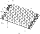
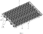
- a battery module including a mounting bracket 1, a bus bar assembly 2, a plurality of cells 3, and an FPC board assembly 4.
- the mounting bracket 1 includes a first mounting surface 11 and a second mounting surface 12 disposed opposite to each other 1, where the first mounting surface 11 is provided with a plurality of fixing plates 13.
- the busbar assembly 2 is detachably connected to the mounting bracket 1 and disposed on the second mounting surface 12.
- the plurality of cells 3 are arranged on the first mounting surface 11 and connected to the bus bar assembly 2.
- the FPC board assembly 4 includes a plurality of FPC boards 41 and a plurality of connectors 42.
- the FPC boards 41 are vertically arranged on the first mounting surface 11, and thus the FPC boards 41 do not affect the assembling of the cells 3, so that the busbar assembly 2, the mounting bracket 1, and the FPC board assembly 4 can be pre-assembled in advance.
- the busbar assembly 2, the mounting bracket 1, and the FPC board assembly 4 are assembled in the preceding working procedure, so that the integrated feeding is realized at the assembling station of the cells 3, the types of the materials are reduced, difficulty of the material management and control is reduced, the occupation of equipment and a field is reduced, and the assembly efficiency and the product quality are improved.
- connection end 411 of each of the FPC boards 41 is fixedly connected to respective one of the connectors 42 and riveted to respective one of the fixing boards 13, so that installation of the connector 42 is implemented.
- the mounting bracket 1 is manufactured from a plastic material, and is easily riveted to the connection end 411 by a hot riveting connection. The manufacturing process is simple, the manufacturing cost is low, the fixing is reliable, and no looseness is generated. The vibration of the battery module in use makes it difficult to cause the vibration of the connector 42, thereby avoiding poor acquisition contact and ensuring the working reliability of the battery module.
- the FPC board assembly further includes a plurality of reinforcing plates 43.
- each of the reinforcing plates 43 is connected to a side of respective one of the connection ends 411 away from respective one of the connectors 42 and riveted to respective one of the fixing plates 13.
- the reinforcing plate 43 is capable of increasing the strength of the connection end 411 and fixing the connector 42 more firmly.
- the fixing plate 13 is provided with a plurality of riveting posts 131, the reinforcing plate 43 and the connection end 411 both are provided with a plurality of positioning holes 40 through which the riveting posts 131 can pass and be riveted to the reinforcing plate 43 and the connection end 411.
- the mounting bracket 1 further includes a plurality of reinforcing ribs 14. As shown in FIG. 3 , each of the reinforcing ribs 14 is connected to a side of respective one of the fixing plates 13 away from respective one of the connection ends 411.
- the mounting bracket 1 of the present embodiment is provided with four reinforcing ribs 14, which are parallel to each other and arranged at intervals. One end of the reinforcing rib 14 is connected to one side of the fixing plate 13 away from the connection end 411, and the other end of the reinforcing rib 14 is connected to the first mounting surface 11.
- the reinforcing ribs 14 can increase the strength of the mounting bracket 1 and prevent the mounting of the FPC board assembly 4 from being insufficient.
- the busbar assembly 2 includes a negative output busbar 21.
- the negative output busbar 21 includes a bent output end 211 parallel to an axial direction of the cells 3 and configured to connect an adjacent battery module.
- the bent output end 211 is attached to the mounting bracket 1 and provided with a connection bolt 212, an axial direction of the connection bolt 212 is perpendicular to a side surface of the mounting bracket 1, and the connection bolt 212 is configured to connect the adjacent battery module and screwed to a mounting hole 2111 of the bent output end 211.
- the bent output end 211 is formed by a sheet metal bending process, and the length of the bent output end 211 extends along the axial direction of the cells 3.
- the bent output end 211 does not increase the length of each of the cells 3 in the horizontal direction, thereby reducing space occupation.
- the battery module and the adjacent battery module can be tightened by the connection bolt 212 in the horizontal direction, thereby greatly increasing the space utilization rate.
- the plurality of FPC boards 41 include a first FPC board 412 embedded among the plurality of cells 3 and a second FPC board 413 disposed around an outer periphery of the cells 3.
- the battery module of the present embodiment includes two first FPC boards 412 and one second FPC board 413.
- the two first FPC boards 412 are penetrated among the plurality of cells 3 to reduce the space occupation and do not block the first mounting surface 11 or the second mounting surface 12, and do not affect a welding connection between each of the cells 3 and the busbar assembly 2, thereby facilitating the integrated feeding.
- the first FPC board 412 includes a bent extension portion capable of attaching a side of the plurality of cells 3.
- the bent extension portion has a wavy cross section and easily attaches an outer surface of a cylindrical cell 3.
- the first FPC plate 412 extends in a straight line at both ends of the bent extension portion to facilitate the fixing.
- the mounting bracket 1 includes a plurality of first limiting members 15. As shown in FIGS. 6 and 7 , the first limiting members 15 are protruded on the first mounting surface 11 and configured to snap-fit the cells 3. Illustratively, the mounting bracket 1 further includes a plurality of second limiting members 16. As shown in FIGS. 8 and 9 , the second limiting members 16 are protruded on the second mounting surface 12 and configured to snap-fit the busbar assembly 2.
- each of the cells 3 is cylindrical in shape
- each of the first limiting members 15 is composed of six protrusions with arc surfaces, where the protrusions are protruded on the first mounting surface 11, and the arc surfaces of the six protrusions are provided concentrically, so that the protrusions can be attached to the cell 3, the positioning accuracy of the cell 3 is increased, and the assembly efficiency of the cell 3 is improved.
- Each of the second limiting members 16 is designed according to an appearance shape of the bus bar assembly 2 and consists of a plurality of protrusions including curved surfaces and flat surfaces.
- the configuration of the first limiting members 15 and the second limiting members 16 may vary depending on the appearance shapes of the cell 3 and the busbar assembly 2.
Landscapes
- Chemical & Material Sciences (AREA)
- Chemical Kinetics & Catalysis (AREA)
- Electrochemistry (AREA)
- General Chemical & Material Sciences (AREA)
- Engineering & Computer Science (AREA)
- Microelectronics & Electronic Packaging (AREA)
- Manufacturing & Machinery (AREA)
- Battery Mounting, Suspending (AREA)
- Connection Of Batteries Or Terminals (AREA)
Abstract
Description
- This application claims priority to
Chinese Patent Application No. 202222956571.5, filed with the Chinese Patent Office on November 7, 2022 - The present application relates to the field of battery technologies, and for example to a battery module.
- The smallest unit of a power battery is a cell. One power battery includes hundreds of individual cells, where a group of cells may form a battery module, and a plurality of battery modules may form the power battery. In order to fix position of the cells, the battery module is generally provided with a mounting bracket, and assembling of the battery module includes fixing structural members such as cells, an Flexible Printed Circuit (FPC) board, an acquisition wiring harness, a connector, and a busbar to the mounting bracket. If these structural members are all separately fed, it will result in an increase in the types of materials, an increase in the difficulty of material management and control, and an impact on assembly efficiency and product quality at an assembling station of the battery module.
- In addition, the connector is generally installed in a manner of snap connection for the battery module in the related art and fixed to the mounting bracket by the snap. Since the snap is easily loosened and vibration of the battery module in use may cause the connector to shake, resulting in a poor acquisition contact and affecting reliability of the battery module.
- The present application provides a battery module capable of realizing integrated feeding at a cell assembling station, and reliable riveting connection between a connector and a mounting bracket, thereby improving assembly efficiency and assembly quality and ensuring work reliability.
- The present application provides a battery module, including:
- a mounting bracket including a first mounting surface and a second mounting surface disposed opposite to each other, where the first mounting surface is provided with a plurality of fixing plates;
- a busbar assembly detachably connected to the mounting bracket and disposed on the second mounting surface;
- a plurality of cells arranged on the first mounting surface and connected to the busbar assembly; and
- an FPC board assembly including a plurality of FPC boards and a plurality of connectors, where the FPC boards are vertically disposed on the first mounting surface, and a connection end of each of the FPC boards is fixedly connected to respective one of the connectors and riveted to respective one of the fixing plates.
- In an embodiment, the FPC board assembly further includes a reinforcing plate connected to a side of the connection end away from the connector and riveted to the fixing plate.
- In an embodiment, the fixing plate is provided with a plurality of riveting posts, the reinforcing plate and the connection end both are provided with a plurality of positioning holes through which the riveting posts can pass and be riveted to the reinforcing plate and the connection end.
- In an embodiment, the mounting bracket further includes a plurality of reinforcing ribs each connected to a side of the fixing plate away from the connection end.
- In an embodiment, the busbar assembly includes a negative output busbar, where the negative output busbar includes a bent output end parallel to an axial direction of the cell and configured to connect an adjacent battery module.
- In an embodiment, the bent output end is attached to the mounting bracket and provided with a connection bolt, an axial direction of the connection bolt is perpendicular to a side surface of the mounting bracket, and the connection bolt is configured to connect the adjacent battery module and screwed to a mounting hole of the bent output end.
- In an embodiment, the plurality of FPC boards include a first FPC board embedded among the plurality of cells and a second FPC board disposed around an outer periphery of the cells.
- In an embodiment, the first FPC board includes a bent extension portion capable of attaching a side of the plurality of cells.
- In an embodiment, the mounting bracket includes a plurality of first limiting members protruded on the first mounting surface and configured to snap-fit the cells.
- In an embodiment, the mounting bracket includes a plurality of second limiting members protruded on the second mounting surface and configured to snap-fit the busbar assembly.
- According to the battery module provided in the present application, the FPC boards are vertically arranged on the first mounting surface, and thus the FPC boards do not affect the assembling of the cells, so that the busbar assembly, the mounting bracket, and the FPC board assembly can be pre-assembled in advance. The busbar assembly, the mounting bracket, and the FPC board assembly are assembled in a preceding working procedure, so that the integrated feeding is realized, the types of the materials are reduced, difficulty of the material management and control is reduced, the occupation of equipment and a field is reduced, and the assembly efficiency and the product quality are improved. At the same time, the connection end of the FPC board is fixedly connected to the connector and riveted to the fixing plate, so that the installation of the connector is realized, the manufacturing process is simple, the processing cost is low, the fixing is reliable, the looseness does not occur, even the vibration of the battery module in use is difficult to cause the vibration of the connector, the poor acquisition contact is avoided, and the working reliability of the battery module is ensured.
-
-
FIG. 1 is a first schematic structural diagram of a battery module according to some embodiments of the present application. -
FIG. 2 is a second schematic structural diagram of a battery module according to some embodiments of the present application. -
FIG. 3 is a partially enlarged view of a portion A of the battery module inFIG. 1 . -
FIG. 4 is a partially enlarged view of a portion B of the battery module inFIG. 2 . -
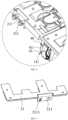
FIG. 5 is a schematic structural diagram of a negative output busbar according to some embodiments of the present application. -
FIG. 6 is a first schematic structural diagram of a mounting bracket according to some embodiments of the present application. -
FIG. 7 is a partially enlarged view of a portion C of the battery module inFIG. 6 . -
FIG. 8 is a second schematic structural diagram of a mounting bracket according to some embodiments of the present application. -
FIG. 9 is a partially enlarged view of a portion D of the battery module inFIG. 8 . - In FIGS:
1. Mounting bracket; 11. First mounting surface; 12. Second mounting surface; 13. Fixing plate; 131. Riveting post; 14. Reinforcing rib; 15. First limiting member; 16. Second limiting member; 2. Busbar assembly; 21. Negative output busbar; 211. Bent output end; 2111. Mounting hole; 212. Connection bolt; 3. Cell; 4. FPC board assembly; 40. Positioning hole; 41. FPC board; 411. Connection end; 412. First FPC board; 413. Second FPC board; 42. Connector; 43. Reinforcing plate. - In description of the present application, it should be noted that the terms "interconnection", "connection" and "fixing" should be understood in a broad sense, unless otherwise clearly specified. For example, "fixing" can be a fixed connection, a detachable connection, or integrated connection. It can be a mechanical connection or an electrical connection. It can be directly connected or indirectly connected through an intermediary. It can also be the connection between two elements or the interaction between two elements. Those ordinary skilled in the art can understand the meanings of the above terms in the present application according to actual situations.
- In the present application, it should he noted that unless otherwise clearly specified, a first feature "on" or "under" a second feature may mean that the first feature directly contacts the second feature, or that the first feature contacts the second feature via an additional feature there between instead of directly contacting the second feature. Moreover, the first feature "on", "above", and "over" the second feature may mean that the first feature is right over or obliquely upward over the second feature or mean that the first feature has a horizontal height higher than that of the second feature. The first feature "under", "below", and "beneath" the second feature may mean that the first feature is right beneath or obliquely downward beneath the second feature or mean that horizontal height of the first feature is lower than that of the second feature.
- In the description of the embodiments, orientations or position relationships indicated by the terms "upper", "lower", "left", "right" are based on orientations or position relationships illustrated in the drawings. The terms are used to facilitate the description and simplify the operations, rather than indicate or imply that the devices or elements referred to herein are required to have specific orientations or be constructed or operate in the specific orientations. In addition, the terms "first" and "second" are used solely for the purpose of distinguishing elements in terms of description of the elements and not in a particular sense.
- The smallest unit of a power battery is a cell. The power battery includes hundreds of individual cells, where a group of cells may form a battery module, and a plurality of battery modules may form the power battery. The assembling of the battery module includes fixing the structural members such as the cells, the FPC board, the acquisition wiring harness, the connector, and the busbar to the mounting bracket. If these structural members are all separately fed, it will result in the increase in the types of materials, the increase in the difficulty of material management and control, and the impact on the assembly efficiency and the product quality at the assembling station of the battery module. If the structural members such as the FPC board, the connector, and the busbar, and the mounting bracket are integrally assembled and fed together in a preceding working procedure, the FPC board and the busbar occupy a larger space area, and is easily interfered with the fixing mounting of the cells. It is also necessary to disassemble the FPC board, and then assemble the FPC board to the mounting bracket after completing installation of the cells, thereby adding additional process and seriously affecting the mounting efficiency.
- In addition, the connector is generally installed in a manner of snap connection for the battery module in the related art and fixed to the mounting bracket by the snap. Since the snap is easily loosened and vibration of the battery module in use may cause the connector to shake, resulting in the poor acquisition contact and affecting reliability of the battery module. In order to solve the above technical problems, embodiments of the present application provide a battery module.
- As shown in
FIGS. 1 to 9 , embodiments of the present application provide a battery module, including a mountingbracket 1, abus bar assembly 2, a plurality ofcells 3, and anFPC board assembly 4. The mountingbracket 1 includes a first mountingsurface 11 and a second mountingsurface 12 disposed opposite to each other 1, where the first mountingsurface 11 is provided with a plurality of fixingplates 13. Thebusbar assembly 2 is detachably connected to the mountingbracket 1 and disposed on the second mountingsurface 12. The plurality ofcells 3 are arranged on the first mountingsurface 11 and connected to thebus bar assembly 2. TheFPC board assembly 4 includes a plurality ofFPC boards 41 and a plurality ofconnectors 42. TheFPC boards 41 are vertically arranged on the first mountingsurface 11, and thus theFPC boards 41 do not affect the assembling of thecells 3, so that thebusbar assembly 2, the mountingbracket 1, and theFPC board assembly 4 can be pre-assembled in advance. Thebusbar assembly 2, the mountingbracket 1, and theFPC board assembly 4 are assembled in the preceding working procedure, so that the integrated feeding is realized at the assembling station of thecells 3, the types of the materials are reduced, difficulty of the material management and control is reduced, the occupation of equipment and a field is reduced, and the assembly efficiency and the product quality are improved. - A
connection end 411 of each of theFPC boards 41 is fixedly connected to respective one of theconnectors 42 and riveted to respective one of the fixingboards 13, so that installation of theconnector 42 is implemented. Alternatively, the mountingbracket 1 is manufactured from a plastic material, and is easily riveted to theconnection end 411 by a hot riveting connection. The manufacturing process is simple, the manufacturing cost is low, the fixing is reliable, and no looseness is generated. The vibration of the battery module in use makes it difficult to cause the vibration of theconnector 42, thereby avoiding poor acquisition contact and ensuring the working reliability of the battery module. - In an embodiment, the FPC board assembly further includes a plurality of reinforcing
plates 43. As shown inFIGS. 3 and4 , each of the reinforcingplates 43 is connected to a side of respective one of the connection ends 411 away from respective one of theconnectors 42 and riveted to respective one of the fixingplates 13. The reinforcingplate 43 is capable of increasing the strength of theconnection end 411 and fixing theconnector 42 more firmly. Illustratively, the fixingplate 13 is provided with a plurality ofriveting posts 131, the reinforcingplate 43 and theconnection end 411 both are provided with a plurality of positioning holes 40 through which theriveting posts 131 can pass and be riveted to the reinforcingplate 43 and theconnection end 411. - In an embodiment, the mounting
bracket 1 further includes a plurality of reinforcingribs 14. As shown inFIG. 3 , each of the reinforcingribs 14 is connected to a side of respective one of the fixingplates 13 away from respective one of the connection ends 411. The mountingbracket 1 of the present embodiment is provided with four reinforcingribs 14, which are parallel to each other and arranged at intervals. One end of the reinforcingrib 14 is connected to one side of the fixingplate 13 away from theconnection end 411, and the other end of the reinforcingrib 14 is connected to the first mountingsurface 11. The reinforcingribs 14 can increase the strength of the mountingbracket 1 and prevent the mounting of theFPC board assembly 4 from being insufficient. - In an embodiment, the
busbar assembly 2 includes anegative output busbar 21. As shown inFIG. 5 , thenegative output busbar 21 includes abent output end 211 parallel to an axial direction of thecells 3 and configured to connect an adjacent battery module. Illustratively, thebent output end 211 is attached to the mountingbracket 1 and provided with aconnection bolt 212, an axial direction of theconnection bolt 212 is perpendicular to a side surface of the mountingbracket 1, and theconnection bolt 212 is configured to connect the adjacent battery module and screwed to a mountinghole 2111 of thebent output end 211. Thebent output end 211 is formed by a sheet metal bending process, and the length of thebent output end 211 extends along the axial direction of thecells 3. Therefore, thebent output end 211 does not increase the length of each of thecells 3 in the horizontal direction, thereby reducing space occupation. When the battery module is connected to the adjacent battery module, the battery module and the adjacent battery module can be tightened by theconnection bolt 212 in the horizontal direction, thereby greatly increasing the space utilization rate. - In an embodiment, the plurality of
FPC boards 41 include afirst FPC board 412 embedded among the plurality ofcells 3 and asecond FPC board 413 disposed around an outer periphery of thecells 3. The battery module of the present embodiment includes twofirst FPC boards 412 and onesecond FPC board 413. The twofirst FPC boards 412 are penetrated among the plurality ofcells 3 to reduce the space occupation and do not block the first mountingsurface 11 or the second mountingsurface 12, and do not affect a welding connection between each of thecells 3 and thebusbar assembly 2, thereby facilitating the integrated feeding. - In an embodiment, the
first FPC board 412 includes a bent extension portion capable of attaching a side of the plurality ofcells 3. The bent extension portion has a wavy cross section and easily attaches an outer surface of acylindrical cell 3. Thefirst FPC plate 412 extends in a straight line at both ends of the bent extension portion to facilitate the fixing. - In an embodiment, the mounting
bracket 1 includes a plurality of first limitingmembers 15. As shown inFIGS. 6 and7 , the first limitingmembers 15 are protruded on the first mountingsurface 11 and configured to snap-fit thecells 3. Illustratively, the mountingbracket 1 further includes a plurality of second limitingmembers 16. As shown inFIGS. 8 and9 , the second limitingmembers 16 are protruded on the second mountingsurface 12 and configured to snap-fit thebusbar assembly 2. In the present embodiment, each of thecells 3 is cylindrical in shape, and each of the first limitingmembers 15 is composed of six protrusions with arc surfaces, where the protrusions are protruded on the first mountingsurface 11, and the arc surfaces of the six protrusions are provided concentrically, so that the protrusions can be attached to thecell 3, the positioning accuracy of thecell 3 is increased, and the assembly efficiency of thecell 3 is improved. Each of the second limitingmembers 16 is designed according to an appearance shape of thebus bar assembly 2 and consists of a plurality of protrusions including curved surfaces and flat surfaces. Of course, in other embodiments, the configuration of the first limitingmembers 15 and the second limitingmembers 16 may vary depending on the appearance shapes of thecell 3 and thebusbar assembly 2.
Claims (10)
- A battery module, comprising:a mounting bracket (1) comprising a first mounting surface (11) and a second mounting surface (12) disposed opposite to each other, wherein the first mounting surface (11) is provided with a plurality of fixing plates (13);a busbar assembly (2) detachably connected to the mounting bracket (1) and disposed on the second mounting surface (12);a plurality of cells (3) arranged on the first mounting surface (11) and connected to the busbar assembly (2); andan Flexible Printed Circuit (FPC) board assembly (4) comprising a plurality of FPC boards (41) and a plurality of connectors (42), wherein the FPC boards (41) are vertically disposed on the first mounting surface (11), and a connection end (411) of each of the FPC boards (41) is fixedly connected to respective one of the connectors (42) and riveted to respective one of the fixing plates (13).
- The battery module of claim 1, wherein the FPC board assembly further comprises a plurality of reinforcing plates (43), each of the reinforcing plates (43) is connected to a side of respective one of the connection ends (411) away from respective one of the connectors and riveted to respective one of the fixing plates (13).
- The battery module of claim 2, wherein the fixing plate (13) is provided with a plurality of riveting posts (131), the reinforcing plate (43) and the connection end (411) both are provided with a plurality of positioning holes (40), and each of the riveting posts (131) is able to pass through respective one of the positioning holes (40) and riveted to the reinforcing plate (43) and the connection end (411).
- The battery module of claim 1, wherein the mounting bracket (1) further comprises a plurality of reinforcing ribs (14) connected to a side of the fixing plates (13) away from the connection ends (411).
- The battery module of claim 1, wherein the busbar assembly (2) comprises a negative output busbar (21), and the negative output busbar (21) comprises a bent output end (211) parallel to an axial direction of the cells (3) and configured to connect an adjacent battery module.
- The battery module of claim 5, wherein the bent output end (211) is attached to the mounting bracket (1) and provided with a connection bolt (212), an axial direction of the connection bolt (211) is perpendicular to a side surface of the mounting bracket (1), and the connection bolt (212) is configured to connect the adjacent battery module and screwed to a mounting hole (2111) of the bent output end (211).
- The battery module of claim 1, wherein the plurality of FPC boards (41) comprise a first FPC board (412) embedded among the plurality of cells (3) and a second FPC board (413) disposed around an outer periphery of the cells (3).
- The battery module of claim 7, wherein the first FPC board comprises a bent extension portion capable of attaching a side surface of each of the plurality of cells (3).
- The battery module of any of claims 1-8, wherein the mounting bracket (1) comprises a plurality of first limiting members (15) protruded on the first mounting surface (11) and configured to snap-fit the cells (3).
- The battery module of any of claims 1-8, wherein the mounting bracket (1) comprises a plurality of second limiting members (16) protruded on the second mounting surface (12) and configured to snap-fit the busbar assembly (2).
Applications Claiming Priority (2)
| Application Number | Priority Date | Filing Date | Title |
|---|---|---|---|
| CN202222956571.5U CN218731649U (en) | 2022-11-07 | 2022-11-07 | Battery module |
| PCT/CN2022/135749 WO2024098478A1 (en) | 2022-11-07 | 2022-12-01 | Battery module |
Publications (2)
| Publication Number | Publication Date |
|---|---|
| EP4391203A1 true EP4391203A1 (en) | 2024-06-26 |
| EP4391203A4 EP4391203A4 (en) | 2025-01-22 |
Family
ID=85609024
Family Applications (1)
| Application Number | Title | Priority Date | Filing Date |
|---|---|---|---|
| EP22932493.4A Pending EP4391203A4 (en) | 2022-11-07 | 2022-12-01 | BATTERY MODULE |
Country Status (4)
| Country | Link |
|---|---|
| US (1) | US20240322327A1 (en) |
| EP (1) | EP4391203A4 (en) |
| CN (1) | CN218731649U (en) |
| WO (1) | WO2024098478A1 (en) |
Families Citing this family (1)
| Publication number | Priority date | Publication date | Assignee | Title |
|---|---|---|---|---|
| EP4693653A4 (en) * | 2023-04-07 | 2026-08-05 | Eve Energy Co Ltd | BATTERY CELL COMPARTMENT, BATTERY MODULE AND BATTERY PACK |
Family Cites Families (14)
| Publication number | Priority date | Publication date | Assignee | Title |
|---|---|---|---|---|
| JP6757856B2 (en) * | 2016-12-27 | 2020-09-23 | ユラ・コーポレイション・カンパニー・リミテッドYura Corporation Co., Ltd. | Busbar assembly and frame assembly |
| KR101996449B1 (en) * | 2017-09-06 | 2019-07-03 | 주식회사 유라코퍼레이션 | Battery cell module with protective structure of fpcb |
| CN109301634B (en) * | 2017-07-24 | 2020-06-19 | 莫仕连接器(成都)有限公司 | Battery connection module |
| US20190131672A1 (en) * | 2017-11-01 | 2019-05-02 | Lithos Energy, Inc. | High power battery modules with pcb sensing assembly |
| CN111699571B (en) * | 2018-02-22 | 2023-01-17 | 三洋电机株式会社 | Battery pack and its manufacturing method |
| EP3678213A1 (en) * | 2019-01-07 | 2020-07-08 | Andreas Stihl AG & Co. KG | Cell holder structure for holding battery cells |
| CN211530005U (en) * | 2019-12-20 | 2020-09-18 | 十堰猛狮新能源科技有限公司 | Electric motor car battery module and be used for busbar of battery module |
| JP7367182B2 (en) * | 2020-01-08 | 2023-10-23 | エルジー エナジー ソリューション リミテッド | Battery packs, electronic devices and automobiles |
| CN212808546U (en) * | 2020-07-13 | 2021-03-26 | 东莞市硅翔绝缘材料有限公司 | Integrated device for voltage acquisition and battery monitoring |
| CN213340487U (en) * | 2020-10-10 | 2021-06-01 | 湖北亿纬动力有限公司 | battery module |
| CN213816347U (en) * | 2020-11-09 | 2021-07-27 | 湖北亿纬动力有限公司 | A battery module |
| CN214313459U (en) * | 2021-09-06 | 2021-09-28 | 江苏索尔新能源科技股份有限公司 | A sampling subassembly for battery module |
| CN216251013U (en) * | 2021-09-30 | 2022-04-08 | 蜂巢能源科技有限公司 | Cylindrical battery module |
| CN217656040U (en) * | 2022-06-29 | 2022-10-25 | 蜂巢能源科技股份有限公司 | Battery module and energy storage equipment |
-
2022
- 2022-11-07 CN CN202222956571.5U patent/CN218731649U/en active Active
- 2022-12-01 WO PCT/CN2022/135749 patent/WO2024098478A1/en not_active Ceased
- 2022-12-01 US US18/284,370 patent/US20240322327A1/en not_active Abandoned
- 2022-12-01 EP EP22932493.4A patent/EP4391203A4/en active Pending
Also Published As
| Publication number | Publication date |
|---|---|
| EP4391203A4 (en) | 2025-01-22 |
| WO2024098478A1 (en) | 2024-05-16 |
| US20240322327A1 (en) | 2024-09-26 |
| CN218731649U (en) | 2023-03-24 |
Similar Documents
| Publication | Publication Date | Title |
|---|---|---|
| EP3599652B1 (en) | Isolation board assembly and battery module | |
| EP4254630A1 (en) | Wire harness isolation plate and battery module | |
| CN218602661U (en) | Partition plate assembly and battery module | |
| EP3905363B1 (en) | Battery module | |
| CN221281488U (en) | Beam module and server | |
| US20240322327A1 (en) | Battery module | |
| EP3754746B1 (en) | Bus bar module | |
| CN215266595U (en) | A battery module | |
| EP4210180A1 (en) | Connector assembly and manufacturing method therefor, and electronic device | |
| CN211150540U (en) | Diode fixing structure and solar cell module junction box | |
| EP4432316A1 (en) | Reactor and electrical device | |
| WO2021049667A1 (en) | Secondary cell module | |
| CN223141234U (en) | A CCS bracket, CCS component and battery module | |
| CN216819796U (en) | Axial diode and photovoltaic junction box and photovoltaic module comprising same | |
| CN217048246U (en) | A installing support and vehicle for battery | |
| CN210628522U (en) | A ladder type wiring device | |
| CN222940140U (en) | CCS components and batteries | |
| CN220606219U (en) | Converter components and fuel cell systems | |
| EP4404351B1 (en) | Battery module | |
| CN217741646U (en) | Photovoltaic module and C shaped steel connecting device | |
| CN224264288U (en) | Copper bar assembly and power backboard | |
| EP4708598A1 (en) | Bracket structure and battery pack | |
| CN223956751U (en) | A battery pack | |
| CN224204277U (en) | Battery pack and battery pack | |
| CN218351910U (en) | Mounting structure of wiring bracket for secondary wire of switch cabinet |
Legal Events
| Date | Code | Title | Description |
|---|---|---|---|
| STAA | Information on the status of an ep patent application or granted ep patent |
Free format text: STATUS: UNKNOWN |
|
| STAA | Information on the status of an ep patent application or granted ep patent |
Free format text: STATUS: THE INTERNATIONAL PUBLICATION HAS BEEN MADE |
|
| PUAI | Public reference made under article 153(3) epc to a published international application that has entered the european phase |
Free format text: ORIGINAL CODE: 0009012 |
|
| STAA | Information on the status of an ep patent application or granted ep patent |
Free format text: STATUS: REQUEST FOR EXAMINATION WAS MADE |
|
| 17P | Request for examination filed |
Effective date: 20230928 |
|
| AK | Designated contracting states |
Kind code of ref document: A1 Designated state(s): AL AT BE BG CH CY CZ DE DK EE ES FI FR GB GR HR HU IE IS IT LI LT LU LV MC ME MK MT NL NO PL PT RO RS SE SI SK SM TR |
|
| A4 | Supplementary search report drawn up and despatched |
Effective date: 20241223 |
|
| RIC1 | Information provided on ipc code assigned before grant |
Ipc: H01M 50/244 20210101ALI20241217BHEP Ipc: H01M 50/209 20210101ALI20241217BHEP Ipc: H01M 10/42 20060101ALI20241217BHEP Ipc: H01M 50/258 20210101ALI20241217BHEP Ipc: H01M 50/213 20210101ALI20241217BHEP Ipc: H01M 50/284 20210101ALI20241217BHEP Ipc: H05K 1/02 20060101ALI20241217BHEP Ipc: H05K 1/18 20060101ALI20241217BHEP Ipc: H01M 50/507 20210101ALI20241217BHEP Ipc: H01M 50/519 20210101AFI20241217BHEP |
|
| DAV | Request for validation of the european patent (deleted) | ||
| DAX | Request for extension of the european patent (deleted) | ||
| GRAP | Despatch of communication of intention to grant a patent |
Free format text: ORIGINAL CODE: EPIDOSNIGR1 |
|
| STAA | Information on the status of an ep patent application or granted ep patent |
Free format text: STATUS: GRANT OF PATENT IS INTENDED |
|
| RIC1 | Information provided on ipc code assigned before grant |
Ipc: H01M 50/519 20210101AFI20260430BHEP Ipc: H01M 50/209 20210101ALI20260430BHEP Ipc: H01M 50/244 20210101ALI20260430BHEP Ipc: H05K 1/189 20260101ALI20260430BHEP Ipc: H01M 50/507 20210101ALI20260430BHEP Ipc: H05K 1/18 20060101ALI20260430BHEP Ipc: H01M 10/42 20060101ALI20260430BHEP Ipc: H05K 1/02 20060101ALI20260430BHEP Ipc: H01M 50/284 20210101ALI20260430BHEP Ipc: H01M 50/258 20210101ALI20260430BHEP Ipc: H01M 50/213 20210101ALI20260430BHEP |
|
| INTG | Intention to grant announced |
Effective date: 20260528 |