EP4391184A1 - Battery pack having double top cover with venting gas discharge passage180324 - Google Patents
Battery pack having double top cover with venting gas discharge passage180324 Download PDFInfo
- Publication number
- EP4391184A1 EP4391184A1 EP23855092.5A EP23855092A EP4391184A1 EP 4391184 A1 EP4391184 A1 EP 4391184A1 EP 23855092 A EP23855092 A EP 23855092A EP 4391184 A1 EP4391184 A1 EP 4391184A1
- Authority
- EP
- European Patent Office
- Prior art keywords
- battery pack
- battery
- flame
- pack
- battery module
- Prior art date
- Legal status (The legal status is an assumption and is not a legal conclusion. Google has not performed a legal analysis and makes no representation as to the accuracy of the status listed.)
- Granted
Links
Images


Classifications
-
- H—ELECTRICITY
- H01—ELECTRIC ELEMENTS
- H01M—PROCESSES OR MEANS, e.g. BATTERIES, FOR THE DIRECT CONVERSION OF CHEMICAL ENERGY INTO ELECTRICAL ENERGY
- H01M50/00—Constructional details or processes of manufacture of the non-active parts of electrochemical cells other than fuel cells, e.g. hybrid cells
- H01M50/30—Arrangements for facilitating escape of gases
-
- H—ELECTRICITY
- H01—ELECTRIC ELEMENTS
- H01M—PROCESSES OR MEANS, e.g. BATTERIES, FOR THE DIRECT CONVERSION OF CHEMICAL ENERGY INTO ELECTRICAL ENERGY
- H01M50/00—Constructional details or processes of manufacture of the non-active parts of electrochemical cells other than fuel cells, e.g. hybrid cells
- H01M50/20—Mountings; Secondary casings or frames; Racks, modules or packs; Suspension devices; Shock absorbers; Transport or carrying devices; Holders
- H01M50/204—Racks, modules or packs for multiple batteries or multiple cells
-
- H—ELECTRICITY
- H01—ELECTRIC ELEMENTS
- H01M—PROCESSES OR MEANS, e.g. BATTERIES, FOR THE DIRECT CONVERSION OF CHEMICAL ENERGY INTO ELECTRICAL ENERGY
- H01M50/00—Constructional details or processes of manufacture of the non-active parts of electrochemical cells other than fuel cells, e.g. hybrid cells
- H01M50/20—Mountings; Secondary casings or frames; Racks, modules or packs; Suspension devices; Shock absorbers; Transport or carrying devices; Holders
- H01M50/249—Mountings; Secondary casings or frames; Racks, modules or packs; Suspension devices; Shock absorbers; Transport or carrying devices; Holders specially adapted for aircraft or vehicles, e.g. cars or trains
-
- H—ELECTRICITY
- H01—ELECTRIC ELEMENTS
- H01M—PROCESSES OR MEANS, e.g. BATTERIES, FOR THE DIRECT CONVERSION OF CHEMICAL ENERGY INTO ELECTRICAL ENERGY
- H01M50/00—Constructional details or processes of manufacture of the non-active parts of electrochemical cells other than fuel cells, e.g. hybrid cells
- H01M50/20—Mountings; Secondary casings or frames; Racks, modules or packs; Suspension devices; Shock absorbers; Transport or carrying devices; Holders
- H01M50/271—Lids or covers for the racks or secondary casings
-
- H—ELECTRICITY
- H01—ELECTRIC ELEMENTS
- H01M—PROCESSES OR MEANS, e.g. BATTERIES, FOR THE DIRECT CONVERSION OF CHEMICAL ENERGY INTO ELECTRICAL ENERGY
- H01M50/00—Constructional details or processes of manufacture of the non-active parts of electrochemical cells other than fuel cells, e.g. hybrid cells
- H01M50/20—Mountings; Secondary casings or frames; Racks, modules or packs; Suspension devices; Shock absorbers; Transport or carrying devices; Holders
- H01M50/289—Mountings; Secondary casings or frames; Racks, modules or packs; Suspension devices; Shock absorbers; Transport or carrying devices; Holders characterised by spacing elements or positioning means within frames, racks or packs
-
- H—ELECTRICITY
- H01—ELECTRIC ELEMENTS
- H01M—PROCESSES OR MEANS, e.g. BATTERIES, FOR THE DIRECT CONVERSION OF CHEMICAL ENERGY INTO ELECTRICAL ENERGY
- H01M50/00—Constructional details or processes of manufacture of the non-active parts of electrochemical cells other than fuel cells, e.g. hybrid cells
- H01M50/30—Arrangements for facilitating escape of gases
- H01M50/342—Non-re-sealable arrangements
- H01M50/3425—Non-re-sealable arrangements in the form of rupturable membranes or weakened parts, e.g. pierced with the aid of a sharp member
-
- H—ELECTRICITY
- H01—ELECTRIC ELEMENTS
- H01M—PROCESSES OR MEANS, e.g. BATTERIES, FOR THE DIRECT CONVERSION OF CHEMICAL ENERGY INTO ELECTRICAL ENERGY
- H01M50/00—Constructional details or processes of manufacture of the non-active parts of electrochemical cells other than fuel cells, e.g. hybrid cells
- H01M50/30—Arrangements for facilitating escape of gases
- H01M50/35—Gas exhaust passages comprising elongated, tortuous or labyrinth-shaped exhaust passages
- H01M50/367—Internal gas exhaust passages forming part of the battery cover or case; Double cover vent systems
-
- H—ELECTRICITY
- H01—ELECTRIC ELEMENTS
- H01M—PROCESSES OR MEANS, e.g. BATTERIES, FOR THE DIRECT CONVERSION OF CHEMICAL ENERGY INTO ELECTRICAL ENERGY
- H01M50/00—Constructional details or processes of manufacture of the non-active parts of electrochemical cells other than fuel cells, e.g. hybrid cells
- H01M50/30—Arrangements for facilitating escape of gases
- H01M50/383—Flame arresting or ignition-preventing means
-
- H—ELECTRICITY
- H01—ELECTRIC ELEMENTS
- H01M—PROCESSES OR MEANS, e.g. BATTERIES, FOR THE DIRECT CONVERSION OF CHEMICAL ENERGY INTO ELECTRICAL ENERGY
- H01M50/00—Constructional details or processes of manufacture of the non-active parts of electrochemical cells other than fuel cells, e.g. hybrid cells
- H01M50/30—Arrangements for facilitating escape of gases
- H01M50/394—Gas-pervious parts or elements
-
- H—ELECTRICITY
- H01—ELECTRIC ELEMENTS
- H01M—PROCESSES OR MEANS, e.g. BATTERIES, FOR THE DIRECT CONVERSION OF CHEMICAL ENERGY INTO ELECTRICAL ENERGY
- H01M2220/00—Batteries for particular applications
- H01M2220/20—Batteries in motive systems, e.g. vehicle, ship, plane
-
- Y—GENERAL TAGGING OF NEW TECHNOLOGICAL DEVELOPMENTS; GENERAL TAGGING OF CROSS-SECTIONAL TECHNOLOGIES SPANNING OVER SEVERAL SECTIONS OF THE IPC; TECHNICAL SUBJECTS COVERED BY FORMER USPC CROSS-REFERENCE ART COLLECTIONS [XRACs] AND DIGESTS
- Y02—TECHNOLOGIES OR APPLICATIONS FOR MITIGATION OR ADAPTATION AGAINST CLIMATE CHANGE
- Y02E—REDUCTION OF GREENHOUSE GAS [GHG] EMISSIONS, RELATED TO ENERGY GENERATION, TRANSMISSION OR DISTRIBUTION
- Y02E60/00—Enabling technologies; Technologies with a potential or indirect contribution to GHG emissions mitigation
- Y02E60/10—Energy storage using batteries
Definitions
- the present disclosure relates to a battery pack, and more particularly, to a battery pack for allowing gases to be easily vented to the outdoors and preventing leakage of flames or high temperature particles in the event of a fire in a battery module, thereby preventing or delaying the fire spread to adjacent other battery modules.
- secondary batteries convert electrical energy to chemical energy and can be recharged in a semi-permanent manner.
- Secondary batteries include lithium secondary batteries, nickel-cadmium (Ni-Cd) batteries, lead-acid batteries, nickel-hydrogen (Ni-MH) batteries, zinc-air batteries, alkaline manganese batteries and the like.
- lead-acid batteries and lithium secondary batteries are the most popular secondary batteries.
- lithium secondary batteries have high energy storage density, light weight, compact size, high safety, low discharge rate and long life, and due to these advantages, they are being widely used as electric car batteries in recent years.
- lithium secondary batteries are classified into cylindrical, prismatic and pouch type according to the manufacturing process, and have a wide range of applications including electric cars as well as energy storage systems (ESS) and other electric devices.
- ESS energy storage systems
- a lithium secondary battery cell has an operating voltage of about 2.5V to 4.5V. Accordingly, to use secondary batteries as an energy source for electric vehicles, a plurality of lithium ion battery cells is connected in series and/or in parallel to form a battery module, and battery modules are connected in series and/or in parallel to form a battery pack.
- secondary batteries involve chemical reactions during charging and discharging, when they are used in higher temperature environments than the optimal temperature, performance degradation may occur, and in the case where thermal control to the optimal temperature fails, there are unexpected fire or explosion risks.
- the battery module has a structure in which secondary batteries are densely packed in a module housing, when thermal runaway (heat propagation) occurs or is triggered in any one secondary battery, a large amount of gases may be generated from secondary batteries, and in worse cases, flames and high temperature particles including electrode active materials and aluminum particles may be produced, and during gas venting, the flames and high temperature particles may come out of the corresponding battery module, causing thermal damage to other battery module adjacent to the corresponding battery module, accelerating fires in other battery modules.
- the present disclosure is directed to providing a battery pack for allowing gases to be easily vented to the outdoors through a vent passage and preventing leakage of flames or high temperature particles in the event of a fire in a battery module, thereby preventing or delaying the fire spread to adjacent other battery modules.
- a battery pack includes a pack tray accommodating at least one battery module; a pack cover covering a top of the pack tray, and having a vent passage of venting gas; and a top plate portion disposed between the pack tray and the pack cover and having a lower part facing the battery module and an upper part communicating with the vent passage, wherein the top plate portion is configured to selectively vent the venting gas among flame, high temperature particle and the venting gas generated from the battery module.
- the top plate portion may include a support frame provided in a shape of framework; an upper plate and a lower plate stacked upon each other, with edges supported by the support frame, and having venting holes through which the venting gas is vented; and a flame barrier mesh layer disposed between the upper plate and the lower plate, and configured to prevent leakage of the flame or high temperature particle.
- the top plate portion may further include a flame-retardant pad layer below the lower plate, and the flame-retardant pad layer may have a vent slit in an area corresponding to the venting holes of the lower plate, wherein the vent slit is configured to be torn when higher pressure than an allowable pressure is applied.
- the flame barrier mesh layer may have a mesh structure.
- the pack tray may have an internal partition wall to separate spaces in which the battery modules are disposed, and the top plate portion may be fixed and coupled to the pack tray and the internal partition wall.
- the top plate portion may be coupled to the pack tray and the internal partition wall with fixing screws, and a sealing member may be disposed between the top plate portion and the pack tray.
- the flame-retardant pad layer may include an inlet region portion on a side of the battery module, wherein the inlet region portion is tapered inward in a thicknesswise direction to guide entry of the venting gas.
- the flame-retardant pad layer may include an outlet region portion on a side of the lower plate, wherein the outlet region portion is tapered to expand as much as an inner diameter of the venting hole.
- the vent slit may be in a shape of an H- or I-shaped cut dashed line.
- the vent slit may include a plurality of oval or elliptical shapes having a gradual increase in size.
- a vehicle including the battery pack.
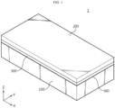
- FIG. 1 is a schematic perspective view of a battery pack according to an embodiment of the present disclosure
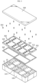
- FIG. 2 is an exploded perspective view of the main components of the battery pack of FIG. 1 .
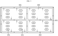
- the battery pack 1 may include a pack tray 100 accommodating at least one battery module 10; a pack cover 200 covering the top of the pack tray 100, and having a vent passage of venting gases inside; and a top plate portion 300 disposed between the pack tray 100 and the pack cover 200, and having a lower part facing the battery module 10 and an upper part communicating with the vent passage, and configured to selectively vent only gases among flames, high temperature particles and gases generated from the battery module 10.
- the pack tray 100 is the component for protecting the battery modules 10 from external impacts, and may be made of a material having high mechanical strength, and as shown in FIGS. 1 and 2 , accommodates the at least one battery module 10.
- the pack tray 100 has a plurality of internal partition walls 110 to separate spaces in which the battery modules 10 are disposed. Although this embodiment shows the pack tray 100 accommodating four battery modules 10, the scope of protection of the present disclosure is not limited to the number of battery modules 10 or the number of internal partition walls 110 of this embodiment.
- the pack cover 200 is configured to cover the top of the pack tray 100, and has the vent passage 210 of venting gases.
- the vent passage 210 may be a sort of gas discharge space or retention or temporary storage space, and although not shown, may have a partition wall, a slit or a baffle to guide a plurality of vent paths. Additionally, for example, bolting, welding, adhesion, hooking or any other coupling method may be used to couple the pack tray 100 to the pack cover 200.
- the battery module 10 is surrounded by a module case 12 (see FIG. 6 ) when received in the pack tray 100.
- the module case 12 has a plurality of holes 11 at two regions on the upper surface, and through which venting gases are vented in the event of a fire in the battery module 10.
- this embodiment discloses top covering of double structure having the vent passage on top of the battery module 10 with the top plate portion 300 interposed between the pack tray 100 and the pack cover 200.
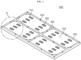
- FIG. 3 is a schematic perspective view of the top plate portion of FIG. 2
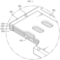
- FIG. 4 is a partial cutaway perspective view of the top plate portion according to an embodiment of the present disclosure
- FIG. 5 is a schematic bottom view of the top plate portion according to an embodiment of the present disclosure
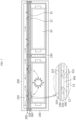
- FIG. 6 is a schematic longitudinal cross-sectional view of the battery pack according to an embodiment of the present disclosure, taken along an X axis direction.
- the top plate portion 300 may be disposed between the pack tray 100 and the pack cover 200 such that the lower part faces the battery module 10 and the upper part communicates with the vent passage 210, and configured to selectively vent only gases among flames, high temperature particles and gases generated from the battery module 10.
- the top plate portion 300 may include a support frame 301 provided in a shape of framework; upper and lower plates 310, 320 stacked upon each other, with edges supported by the support frame 301, and having venting holes 311, 321 through which venting gases are vented, respectively; a flame barrier mesh layer 330 between the upper and lower plates 310, 320 to prevent leakage of flames or high temperature particles; and a flame-retardant pad layer 340 below the lower plate 320.
- the support frame 301 is the framework of the top plate portion 300.
- the support frame 301 accommodates the upper plate and the lower plate, and the support frame 301 is mounted and supported on the upper surface of the pack tray 100 and the internal partition wall 110.
- the support frame 301 has a plurality of screw coupling holes 302, and is screwcoupled along the periphery of the battery module 10 at an area on top of the battery module 10 through fixing screws 350.
- the support frame 301 may be made of a material having high mechanical strength.
- the upper plate 310 has a size corresponding to the size of the battery module 10 to cover the open top of the battery module 10. Additionally, the upper plate 310 is disposed inside the support frame 301 and when disposed inside the support frame 301, there is no height difference between the plate surface of the upper plate 310 and the plate surface of the support frame 301, but in terms of convenience in processing or assembling, the plate surface of the upper plate 310 may be higher or lower than the plate surface of the support frame 301. Meanwhile, in this embodiment, the upper plate 310 is made of stainless steel (SUS) and has high heat absorption and thermal conductivity and high durability against high temperature gases or sparks.
- SUS stainless steel
- the lower plate 320 has substantially the same size and shape as the upper plate 310, and is also made of SUS.
- the plate surface of the upper and lower plates 310, 320 has the plurality of venting holes 311, 321 at the location corresponding to the holes 11 of the battery module 10.
- the venting gases may be vented through the venting holes 311, 321.
- the flame barrier mesh layer 330 is interposed between the upper and lower plates 310, 320. That is, the flame barrier mesh layer 330 closes the venting holes 311, 321 between the upper and lower plates 310, 320.
- the flame barrier mesh layer 330 may have a mesh structure, and be made of a metal that does not easily melt by heat. Accordingly, when flames, high temperature particles and gases generated from the battery module 10 come out of the venting holes 311, 321 via the holes 11, the flames and high temperature particles are blocked by the flame barrier mesh layer 330 so as to prevent leakage, and only the gases are selectively vented.
- the flames, sparks and high temperature particles may be isolated in the corresponding battery module 10 so as to prevent leakage, thereby minimizing thermal damage that may occur to other battery modules 10. Additionally, the large volume of gases that needs to be managed to deal with risks may be easily vented to the outdoors, thereby preventing or delaying thermal runaway in the battery pack.
- the flame-retardant pad layer 340 is disposed in contact with the lower plate 320, and comes into close contact with the battery module 10.
- the flame-retardant pad layer 340 may be made of a material having low thermal conductivity and high heat resistance (for example, silicon, mica). In the presence of the flame-retardant pad layer 340, when a fire occurs in the battery module 10, it is possible to minimize the movement of heat, high temperature particles, flames generated from the corresponding battery module 10 to the upper part of the battery module 10 and propagation to the adjacent battery cells 111.
- the flame-retardant pad layer 340 has a vent slit 341 in an area corresponding to the venting holes 321 of the lower plate 320, and the vent slit 341 is configured to be torn when higher pressure than the allowable pressure is applied.
- the vent slit 341 may be in the shape of an H- or I-shaped cut dashed line. For example, when higher pressure than the allowable design pressure is applied to the battery module 10 in which the fire occurred, the vent slit 341 is torn to allow venting gases to exit.
- the vent slit 341B may include a plurality of oval or elliptical shapes having a gradual increase in size as shown in FIG. 10 .
- the size of the vent slit 341B differentially cut at higher pressure than the allowable design pressure may vary, and in turn, the vent area of venting gases may change.
- the smallest oval or elliptical vent slit 341B may be broken and venting gases may be vented
- the intermediate oval or elliptical vent slit 341B or the largest oval or elliptical vent slit 341B may be broken as well and a larger amount of venting gases may be vented.
- the top plate portion 300 may be coupled to the pack tray 100 and the internal partition wall 110 with the fixing screws 350. Additionally, a sealing member 360 may be disposed between the top plate portion 300 and the pack tray 100 to completely isolate the battery module 10 and the adjacent other battery module 10 from each other.
- FIG. 7 is a diagram showing the vent path of venting gases along the passage in the battery pack according to an embodiment of the present disclosure.
- venting process of venting gases according to this embodiment will be described in detail with reference to FIGS. 1 to 7 .
- the vent slit 341 of the flame-retardant pad layer 340 adjacent to the corresponding battery module 10 is torn and cut and flames and high temperature particles including the venting gases flow upward.
- the mesh structure of the flame barrier mesh layer 330 present on the venting holes 311, 321 of the upper and lower plates 310, 320 allows the venting gases to pass through and does not allow the flames or particles to pass through. Accordingly, it may be possible to easily vent the venting gases to the outdoors and prevent leakage of the flames or high temperature particles, thereby minimizing thermal damage that may occur to other battery modules 10 and preventing or delaying thermal runaway in the battery pack.
- venting gases may pass through the venting holes 311 of the upper plate 310 and temporarily flow or move in the vent passage 210, and although not shown, may be safely vented to the outdoors through an additional vent line.
- the venting gases may enter the adjacent battery module 10, but as shown in FIG. 7 , the vent slit 341 of the flame-retardant pad layer present on the adjacent battery module 10 is still closed, so it may be possible to prevent the venting gases from entering other battery module 10, thereby minimizing thermal damage that may occur to other battery modules 10.
- vent passage 210 takes into account the volume of venting gases, it may be possible to delay thermal damage all over the other battery modules 10 in the battery pack and obtain the evacuation time before thermal runaway.
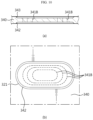
- FIG. 8 is a schematic cross-sectional view and a bottom view of the flame-retardant pad layer according to another embodiment of the present disclosure
- FIG. 9 is a schematic longitudinal cross-sectional view of the battery pack including the top plate portion with the flame-retardant pad layer according to another embodiment of the present disclosure.
- the battery module 10 When compared with the previous embodiment, the battery module 10 according to another embodiment of the present disclosure has an additional configuration to the flame-retardant pad layer 340.
- the flame-retardant pad layer 340 may include an inlet region portion 342 disposed on the battery module 10 side and tapered inward in the thicknesswise direction to guide the entry of venting gases, and an outlet region portion 343 disposed on the lower plate 320 side and tapered to expand as much as the inner diameter of the venting hole 311.
- the inlet region portion 342 is tapered inward in the thicknesswise direction, allowing gases generated from the battery module 10 to enter the venting hole 321 more easily. Additionally, the outlet region portion 343 is disposed on the lower plate 320 side, and tapered to expand as much as the inner diameter of the venting hole 311, allowing easier venting through the venting holes 311 and the vent passage 210.
- vent passage 210 it may be possible to easily vent the gases to the outdoors through the vent passage 210, thereby minimizing thermal damage that may occur to other battery modules 10 and preventing or delaying thermal runaway in the battery pack.
- the flame-retardant pad layer 340 of the second embodiment has the vent slit 341A of smaller thickness or size, and accordingly it may be possible to precisely adjust the pressure range in which the vent slit 341A is cut, thereby achieving fine control of the gas venting according to the amount of venting gases.
- the battery pack 1 may further include a variety of devices for controlling the charge and discharge of the battery modules 10, for example, Battery Management System (BMS), a current sensor, a fuse and the like.
- BMS Battery Management System
- the battery pack 1 according to the present disclosure may be applied to a vehicle such as an electric vehicle or a hybrid electric vehicle. That is, the vehicle according to the present disclosure may include the battery pack 1 according to the present disclosure.
- the battery pack 1 may be installed at a vehicle body frame below the seat or a trunk space, and when installed in the vehicle, the battery pack may be placed upside down where necessary.
Landscapes
- Chemical & Material Sciences (AREA)
- Chemical Kinetics & Catalysis (AREA)
- Electrochemistry (AREA)
- General Chemical & Material Sciences (AREA)
- Engineering & Computer Science (AREA)
- Aviation & Aerospace Engineering (AREA)
- Battery Mounting, Suspending (AREA)
- Gas Exhaust Devices For Batteries (AREA)
- Secondary Cells (AREA)
Abstract
Description
- The present application claims priority to
Korean Patent Application No. 10-2022-0102972 filed on August 17, 2022 - The present disclosure relates to a battery pack, and more particularly, to a battery pack for allowing gases to be easily vented to the outdoors and preventing leakage of flames or high temperature particles in the event of a fire in a battery module, thereby preventing or delaying the fire spread to adjacent other battery modules.
- As opposed to primary batteries that cannot be used again after they are used once, secondary batteries convert electrical energy to chemical energy and can be recharged in a semi-permanent manner.
- Secondary batteries include lithium secondary batteries, nickel-cadmium (Ni-Cd) batteries, lead-acid batteries, nickel-hydrogen (Ni-MH) batteries, zinc-air batteries, alkaline manganese batteries and the like. Among them, lead-acid batteries and lithium secondary batteries are the most popular secondary batteries.
- In particular, lithium secondary batteries have high energy storage density, light weight, compact size, high safety, low discharge rate and long life, and due to these advantages, they are being widely used as electric car batteries in recent years. For reference, in general, lithium secondary batteries are classified into cylindrical, prismatic and pouch type according to the manufacturing process, and have a wide range of applications including electric cars as well as energy storage systems (ESS) and other electric devices.
- Currently, a lithium secondary battery cell has an operating voltage of about 2.5V to 4.5V. Accordingly, to use secondary batteries as an energy source for electric vehicles, a plurality of lithium ion battery cells is connected in series and/or in parallel to form a battery module, and battery modules are connected in series and/or in parallel to form a battery pack.
- Since secondary batteries involve chemical reactions during charging and discharging, when they are used in higher temperature environments than the optimal temperature, performance degradation may occur, and in the case where thermal control to the optimal temperature fails, there are unexpected fire or explosion risks. Additionally, since the battery module has a structure in which secondary batteries are densely packed in a module housing, when thermal runaway (heat propagation) occurs or is triggered in any one secondary battery, a large amount of gases may be generated from secondary batteries, and in worse cases, flames and high temperature particles including electrode active materials and aluminum particles may be produced, and during gas venting, the flames and high temperature particles may come out of the corresponding battery module, causing thermal damage to other battery module adjacent to the corresponding battery module, accelerating fires in other battery modules.
- Accordingly, there is an urgent need for an improved structure of a battery pack for allowing gases to be easily vented to the outdoors and preventing leakage of flames and high temperature sparks in the event of a fire in a battery module.
- To address the above-described problems, the present disclosure is directed to providing a battery pack for allowing gases to be easily vented to the outdoors through a vent passage and preventing leakage of flames or high temperature particles in the event of a fire in a battery module, thereby preventing or delaying the fire spread to adjacent other battery modules.
- The technical problem to be solved by the present disclosure is not limited to the above-described problems, and these and other problems will be clearly understood by those skilled in the art from the following description.
- A battery pack according to the present disclosure includes a pack tray accommodating at least one battery module; a pack cover covering a top of the pack tray, and having a vent passage of venting gas; and a top plate portion disposed between the pack tray and the pack cover and having a lower part facing the battery module and an upper part communicating with the vent passage, wherein the top plate portion is configured to selectively vent the venting gas among flame, high temperature particle and the venting gas generated from the battery module.
- The top plate portion may include a support frame provided in a shape of framework; an upper plate and a lower plate stacked upon each other, with edges supported by the support frame, and having venting holes through which the venting gas is vented; and a flame barrier mesh layer disposed between the upper plate and the lower plate, and configured to prevent leakage of the flame or high temperature particle.
- The top plate portion may further include a flame-retardant pad layer below the lower plate, and the flame-retardant pad layer may have a vent slit in an area corresponding to the venting holes of the lower plate, wherein the vent slit is configured to be torn when higher pressure than an allowable pressure is applied.
- The flame barrier mesh layer may have a mesh structure.
- The pack tray may have an internal partition wall to separate spaces in which the battery modules are disposed, and the top plate portion may be fixed and coupled to the pack tray and the internal partition wall.
- The top plate portion may be coupled to the pack tray and the internal partition wall with fixing screws, and a sealing member may be disposed between the top plate portion and the pack tray.
- The flame-retardant pad layer may include an inlet region portion on a side of the battery module, wherein the inlet region portion is tapered inward in a thicknesswise direction to guide entry of the venting gas.
- The flame-retardant pad layer may include an outlet region portion on a side of the lower plate, wherein the outlet region portion is tapered to expand as much as an inner diameter of the venting hole.
- The vent slit may be in a shape of an H- or I-shaped cut dashed line.
- The vent slit may include a plurality of oval or elliptical shapes having a gradual increase in size.
- According to another aspect of the present disclosure, there is provided a vehicle including the battery pack.
- According to an aspect of the present disclosure, it may be possible to easily vent gases to the outdoors through the vent passage and prevent leakage of flames or high temperature particles in the event of a fire in a battery module, thereby preventing or delaying the fire spread to adjacent other battery modules.
- It may be possible to minimize thermal damage that may occur to other battery modules due to gases and sparks generated from the battery module in which the fire occurred, thereby enhancing durability of the battery pack and reducing the maintenance and repair costs.
- The effect of the present disclosure is not limited to the above-described effects, and these and other effects will be clearly understood by those skilled in the art from this disclosure and the accompanying drawings.
- The accompanying drawings illustrate exemplary embodiments of the present disclosure and together with the following detailed description, serve to provide a further understanding of the technical aspect of the present disclosure, and thus the present disclosure should not be construed as being limited to the drawings.
-
FIG. 1 is a schematic perspective view of a battery pack according to an embodiment of the present disclosure. -
FIG. 2 is an exploded perspective view of the main components of the battery pack ofFIG. 1 . -
FIG. 3 is a schematic perspective view of a top plate portion ofFIG. 2 . -
FIG. 4 is a partial cutaway perspective view of a top plate portion according to an embodiment of the present disclosure. -
FIG. 5 is a schematic bottom view of a top plate portion according to an embodiment of the present disclosure. -
FIG. 6 is a schematic longitudinal cross-sectional view of a battery pack according to an embodiment of the present disclosure, taken along an X axis direction. -
FIG. 7 is a diagram showing a vent path of venting gas along a passage in a battery pack according to an embodiment of the present disclosure. -
FIG. 8 is a schematic cross-sectional view and a bottom view of a flame-retardant pad layer according to another embodiment of the present disclosure. -
FIG. 9 is a schematic longitudinal cross-sectional view of a battery pack including a top plate portion with a flame-retardant pad layer according to another embodiment of the present disclosure. -
FIG. 10 is a diagram showing a different shape of a vent slit according to still another embodiment of the present disclosure. - Hereinafter, exemplary embodiments of the present disclosure will be described in detail with reference to the accompanying drawings. Prior to the description, it should be understood that the terms or words used in the specification and the appended claims should not be construed as being limited to general and dictionary meanings, but rather interpreted based on the meanings and concepts corresponding to the technical aspect of the present disclosure on the basis of the principle that the inventor is allowed to define the terms appropriately for the best explanation. Therefore, the embodiments described herein and the illustrations shown in the drawings are exemplary embodiments of the present disclosure to describe the technical aspect of the present disclosure and are not intended to be limiting, so it should be understood that a variety of other equivalents and modifications could have been made thereto at the time that the application was filed.
-
FIG. 1 is a schematic perspective view of a battery pack according to an embodiment of the present disclosure, andFIG. 2 is an exploded perspective view of the main components of the battery pack ofFIG. 1 . - The
battery pack 1 according to this embodiment may include apack tray 100 accommodating at least onebattery module 10; apack cover 200 covering the top of thepack tray 100, and having a vent passage of venting gases inside; and atop plate portion 300 disposed between thepack tray 100 and thepack cover 200, and having a lower part facing thebattery module 10 and an upper part communicating with the vent passage, and configured to selectively vent only gases among flames, high temperature particles and gases generated from thebattery module 10. - The
pack tray 100 is the component for protecting thebattery modules 10 from external impacts, and may be made of a material having high mechanical strength, and as shown inFIGS. 1 and2 , accommodates the at least onebattery module 10. - The
pack tray 100 has a plurality ofinternal partition walls 110 to separate spaces in which thebattery modules 10 are disposed. Although this embodiment shows the pack tray 100 accommodating fourbattery modules 10, the scope of protection of the present disclosure is not limited to the number ofbattery modules 10 or the number ofinternal partition walls 110 of this embodiment. - The
pack cover 200 is configured to cover the top of thepack tray 100, and has thevent passage 210 of venting gases. Thevent passage 210 may be a sort of gas discharge space or retention or temporary storage space, and although not shown, may have a partition wall, a slit or a baffle to guide a plurality of vent paths. Additionally, for example, bolting, welding, adhesion, hooking or any other coupling method may be used to couple thepack tray 100 to thepack cover 200. - The
battery module 10 is surrounded by a module case 12 (seeFIG. 6 ) when received in thepack tray 100. Themodule case 12 has a plurality ofholes 11 at two regions on the upper surface, and through which venting gases are vented in the event of a fire in thebattery module 10. - Meanwhile, there is an urgent need for improved structure of the battery pack for allowing gases to be easily vented to the outdoors and preventing leakage of flames and high temperature sparks in the event of a fire in the
battery module 10, and accordingly, this embodiment discloses top covering of double structure having the vent passage on top of thebattery module 10 with thetop plate portion 300 interposed between thepack tray 100 and thepack cover 200. -
FIG. 3 is a schematic perspective view of the top plate portion ofFIG. 2 ,FIG. 4 is a partial cutaway perspective view of the top plate portion according to an embodiment of the present disclosure,FIG. 5 is a schematic bottom view of the top plate portion according to an embodiment of the present disclosure, andFIG. 6 is a schematic longitudinal cross-sectional view of the battery pack according to an embodiment of the present disclosure, taken along an X axis direction. - The
top plate portion 300 may be disposed between thepack tray 100 and thepack cover 200 such that the lower part faces thebattery module 10 and the upper part communicates with thevent passage 210, and configured to selectively vent only gases among flames, high temperature particles and gases generated from thebattery module 10. - To this end, the
top plate portion 300 may include asupport frame 301 provided in a shape of framework; upper andlower plates support frame 301, and havingventing holes barrier mesh layer 330 between the upper andlower plates retardant pad layer 340 below thelower plate 320. - The
support frame 301 is the framework of thetop plate portion 300. Thesupport frame 301 accommodates the upper plate and the lower plate, and thesupport frame 301 is mounted and supported on the upper surface of thepack tray 100 and theinternal partition wall 110. Thesupport frame 301 has a plurality ofscrew coupling holes 302, and is screwcoupled along the periphery of thebattery module 10 at an area on top of thebattery module 10 throughfixing screws 350. Meanwhile, in this embodiment, thesupport frame 301 may be made of a material having high mechanical strength. - The
upper plate 310 has a size corresponding to the size of thebattery module 10 to cover the open top of thebattery module 10. Additionally, theupper plate 310 is disposed inside thesupport frame 301 and when disposed inside thesupport frame 301, there is no height difference between the plate surface of theupper plate 310 and the plate surface of thesupport frame 301, but in terms of convenience in processing or assembling, the plate surface of theupper plate 310 may be higher or lower than the plate surface of thesupport frame 301. Meanwhile, in this embodiment, theupper plate 310 is made of stainless steel (SUS) and has high heat absorption and thermal conductivity and high durability against high temperature gases or sparks. - The
lower plate 320 has substantially the same size and shape as theupper plate 310, and is also made of SUS. - The plate surface of the upper and
lower plates holes holes 11 of thebattery module 10. The venting gases may be vented through the venting holes 311, 321. - Referring primarily to
FIGS. 4 and6 , the flamebarrier mesh layer 330 is interposed between the upper andlower plates barrier mesh layer 330 closes the venting holes 311, 321 between the upper andlower plates barrier mesh layer 330 may have a mesh structure, and be made of a metal that does not easily melt by heat. Accordingly, when flames, high temperature particles and gases generated from thebattery module 10 come out of the venting holes 311, 321 via theholes 11, the flames and high temperature particles are blocked by the flamebarrier mesh layer 330 so as to prevent leakage, and only the gases are selectively vented. - In the end, when flames, sparks and high temperature particles are generated from the
battery module 10 in which the fire occurred, the flames, sparks and high temperature particles may be isolated in thecorresponding battery module 10 so as to prevent leakage, thereby minimizing thermal damage that may occur toother battery modules 10. Additionally, the large volume of gases that needs to be managed to deal with risks may be easily vented to the outdoors, thereby preventing or delaying thermal runaway in the battery pack. - The flame-
retardant pad layer 340 is disposed in contact with thelower plate 320, and comes into close contact with thebattery module 10. Here, the flame-retardant pad layer 340 may be made of a material having low thermal conductivity and high heat resistance (for example, silicon, mica). In the presence of the flame-retardant pad layer 340, when a fire occurs in thebattery module 10, it is possible to minimize the movement of heat, high temperature particles, flames generated from the correspondingbattery module 10 to the upper part of thebattery module 10 and propagation to the adjacent battery cells 111. - The flame-
retardant pad layer 340 has avent slit 341 in an area corresponding to the venting holes 321 of thelower plate 320, and the vent slit 341 is configured to be torn when higher pressure than the allowable pressure is applied. The vent slit 341 may be in the shape of an H- or I-shaped cut dashed line. For example, when higher pressure than the allowable design pressure is applied to thebattery module 10 in which the fire occurred, the vent slit 341 is torn to allow venting gases to exit. - Alternatively, the vent slit 341B may include a plurality of oval or elliptical shapes having a gradual increase in size as shown in
FIG. 10 . In this case, the size of the vent slit 341B differentially cut at higher pressure than the allowable design pressure may vary, and in turn, the vent area of venting gases may change. For example, within a preset pressure range, the smallest oval or elliptical vent slit 341B may be broken and venting gases may be vented, and above the preset pressure range, the intermediate oval or elliptical vent slit 341B or the largest oval or elliptical vent slit 341B may be broken as well and a larger amount of venting gases may be vented. - The
top plate portion 300 may be coupled to thepack tray 100 and theinternal partition wall 110 with the fixing screws 350. Additionally, a sealingmember 360 may be disposed between thetop plate portion 300 and thepack tray 100 to completely isolate thebattery module 10 and the adjacentother battery module 10 from each other. - According to the above-described exemplary configuration, it may be possible to easily vent gases to the outdoors and prevent leakage of flames or high temperature particles in the event of the fire in the
battery module 10. - Additionally, according to the above-described exemplary configuration, it may be possible to minimize thermal damage that may occur to
other battery modules 10 due to gases and sparks generated from thebattery module 10 in which the fire occurred, thereby preventing or delaying thermal runaway in the battery pack. -
FIG. 7 is a diagram showing the vent path of venting gases along the passage in the battery pack according to an embodiment of the present disclosure. - Hereinafter, the venting process of venting gases according to this embodiment will be described in detail with reference to
FIGS. 1 to 7 . - First, as shown in
FIG. 7 , in the event of a fire in thespecific battery module 10, the pressure in themodule case 12 of thecorresponding battery module 10 rises, and accordingly, the pressure below the flame-retardant pad layer 340 rises by venting gases released along theholes 11. - Subsequently, when the pressure rises above the design pressure, the vent slit 341 of the flame-
retardant pad layer 340 adjacent to thecorresponding battery module 10 is torn and cut and flames and high temperature particles including the venting gases flow upward. - Subsequently, the mesh structure of the flame
barrier mesh layer 330 present on the venting holes 311, 321 of the upper andlower plates other battery modules 10 and preventing or delaying thermal runaway in the battery pack. - Subsequently, the venting gases may pass through the venting holes 311 of the
upper plate 310 and temporarily flow or move in thevent passage 210, and although not shown, may be safely vented to the outdoors through an additional vent line. In this process, there is a likelihood that the venting gases may enter theadjacent battery module 10, but as shown inFIG. 7 , the vent slit 341 of the flame-retardant pad layer present on theadjacent battery module 10 is still closed, so it may be possible to prevent the venting gases from enteringother battery module 10, thereby minimizing thermal damage that may occur toother battery modules 10. - In addition, since the
vent passage 210 takes into account the volume of venting gases, it may be possible to delay thermal damage all over theother battery modules 10 in the battery pack and obtain the evacuation time before thermal runaway. - Subsequently, other embodiments of the
battery module 10 of the present disclosure will be briefly described with reference toFIGS. 8 and9 . -
FIG. 8 is a schematic cross-sectional view and a bottom view of the flame-retardant pad layer according to another embodiment of the present disclosure, andFIG. 9 is a schematic longitudinal cross-sectional view of the battery pack including the top plate portion with the flame-retardant pad layer according to another embodiment of the present disclosure. - The same reference numerals as the previous drawings indicate the same elements, and redundant description of the same elements is omitted and difference(s) between this embodiment and the previous embodiment will be described.
- When compared with the previous embodiment, the
battery module 10 according to another embodiment of the present disclosure has an additional configuration to the flame-retardant pad layer 340. The flame-retardant pad layer 340 may include aninlet region portion 342 disposed on thebattery module 10 side and tapered inward in the thicknesswise direction to guide the entry of venting gases, and anoutlet region portion 343 disposed on thelower plate 320 side and tapered to expand as much as the inner diameter of theventing hole 311. - As shown in
FIG. 8 , theinlet region portion 342 is tapered inward in the thicknesswise direction, allowing gases generated from thebattery module 10 to enter theventing hole 321 more easily. Additionally, theoutlet region portion 343 is disposed on thelower plate 320 side, and tapered to expand as much as the inner diameter of theventing hole 311, allowing easier venting through the venting holes 311 and thevent passage 210. - Accordingly, it may be possible to easily vent the gases to the outdoors through the
vent passage 210, thereby minimizing thermal damage that may occur toother battery modules 10 and preventing or delaying thermal runaway in the battery pack. - Additionally, compared to the first embodiment, the flame-
retardant pad layer 340 of the second embodiment has the vent slit 341A of smaller thickness or size, and accordingly it may be possible to precisely adjust the pressure range in which the vent slit 341A is cut, thereby achieving fine control of the gas venting according to the amount of venting gases. - Although not shown, the
battery pack 1 according to the present disclosure may further include a variety of devices for controlling the charge and discharge of thebattery modules 10, for example, Battery Management System (BMS), a current sensor, a fuse and the like. - The
battery pack 1 according to the present disclosure may be applied to a vehicle such as an electric vehicle or a hybrid electric vehicle. That is, the vehicle according to the present disclosure may include thebattery pack 1 according to the present disclosure. Thebattery pack 1 may be installed at a vehicle body frame below the seat or a trunk space, and when installed in the vehicle, the battery pack may be placed upside down where necessary. - The terms indicating directions such as upper, lower, left, right, front and rear are used for convenience of description, but it is obvious to those skilled in the art that the terms may change depending on the position of the stated element or an observer.
- While the present disclosure has been hereinabove described with regard to a limited number of embodiments and drawings, the present disclosure is not limited thereto and it is apparent that a variety of changes and modifications may be made by those skilled in the art within the technical aspect of the present disclosure and the scope of the appended claims and their equivalents.
Claims (11)
- A battery pack, comprising:a pack tray accommodating at least one battery module;a pack cover covering a top of the pack tray, and having a vent passage of venting gas; anda top plate portion disposed between the pack tray and the pack cover and having a lower part facing the battery module and an upper part communicating with the vent passage,wherein the top plate portion is configured to selectively vent the venting gas among flame, high temperature particle and the venting gas generated from the battery module.
- The battery pack according to claim 1, wherein the top plate portion includes:a support frame provided in a shape of framework;an upper plate and a lower plate stacked upon each other, with edges supported by the support frame, and having venting holes through which the venting gas is vented; anda flame barrier mesh layer disposed between the upper plate and the lower plate, and configured to prevent leakage of the flame or high temperature particle.
- The battery pack according to claim 2, wherein the top plate portion further includes a flame-retardant pad layer below the lower plate, and
wherein the flame-retardant pad layer has a vent slit in an area corresponding to the venting holes of the lower plate, wherein the vent slit is configured to be torn when higher pressure than an allowable pressure is applied. - The battery pack according to claim 2, wherein the flame barrier mesh layer has a mesh structure.
- The battery pack according to claim 1, wherein the pack tray has an internal partition wall to separate spaces in which the battery modules are disposed, and
wherein the top plate portion is fixed and coupled to the pack tray and the internal partition wall. - The battery pack according to claim 5, wherein the top plate portion is coupled to the pack tray and the internal partition wall with fixing screws, and
wherein a sealing member is disposed between the top plate portion and the pack tray. - The battery pack according to claim 3, wherein the flame-retardant pad layer includes an inlet region portion on a side of the battery module, wherein the inlet region portion is tapered inward in a thicknesswise direction to guide entry of the venting gas.
- The battery pack according to claim 3, wherein the flame-retardant pad layer includes an outlet region portion on a side of the lower plate, wherein the outlet region portion is tapered to expand as much as an inner diameter of the venting hole.
- The battery pack according to claim 3, wherein the vent slit is in a shape of an H- or I-shaped cut dashed line.
- The battery pack according to claim 3, wherein the vent slit includes a plurality of oval or elliptical shapes having a gradual increase in size.
- A vehicle comprising the battery pack according to any one of claims 1 to 10.
Applications Claiming Priority (2)
| Application Number | Priority Date | Filing Date | Title |
|---|---|---|---|
| KR1020220102972A KR20240024684A (en) | 2022-08-17 | 2022-08-17 | Battery pack having double top cover with venting gas passage |
| PCT/KR2023/011617 WO2024039125A1 (en) | 2022-08-17 | 2023-08-07 | Battery pack having double top cover with venting gas discharge passage |
Publications (3)
| Publication Number | Publication Date |
|---|---|
| EP4391184A1 true EP4391184A1 (en) | 2024-06-26 |
| EP4391184A4 EP4391184A4 (en) | 2025-02-12 |
| EP4391184B1 EP4391184B1 (en) | 2025-11-05 |
Family
ID=89941869
Family Applications (1)
| Application Number | Title | Priority Date | Filing Date |
|---|---|---|---|
| EP23855092.5A Active EP4391184B1 (en) | 2022-08-17 | 2023-08-07 | Battery pack having double top cover with venting gas passage |
Country Status (6)
| Country | Link |
|---|---|
| EP (1) | EP4391184B1 (en) |
| JP (1) | JP7797647B2 (en) |
| KR (1) | KR20240024684A (en) |
| CN (1) | CN118160138A (en) |
| ES (1) | ES3055878T3 (en) |
| WO (1) | WO2024039125A1 (en) |
Cited By (1)
| Publication number | Priority date | Publication date | Assignee | Title |
|---|---|---|---|---|
| EP4478512A4 (en) * | 2022-10-21 | 2025-07-09 | Lg Energy Solution Ltd | BATTERY PACK |
Families Citing this family (11)
| Publication number | Priority date | Publication date | Assignee | Title |
|---|---|---|---|---|
| WO2025198296A1 (en) * | 2024-03-20 | 2025-09-25 | 주식회사 엘지에너지솔루션 | Battery assembly and battery pack comprising same |
| CN222072112U (en) * | 2024-04-01 | 2024-11-26 | 株式会社Aesc日本 | Battery Pack |
| JP2025157844A (en) * | 2024-04-03 | 2025-10-16 | 株式会社Aescジャパン | Battery module |
| KR20250148209A (en) * | 2024-04-05 | 2025-10-14 | 주식회사 엘지에너지솔루션 | Battery pack and vehicle including the same |
| KR20250150407A (en) * | 2024-04-11 | 2025-10-20 | 주식회사 엘지에너지솔루션 | Battery pack and vehicle including the same |
| KR20250158433A (en) * | 2024-04-30 | 2025-11-06 | 주식회사 엘지에너지솔루션 | Battery pack and device including the same |
| KR20250175642A (en) * | 2024-06-10 | 2025-12-17 | 주식회사 엘지에너지솔루션 | Battery module cover assembly, battery pack and vehicle comprising the same |
| KR20250176418A (en) * | 2024-06-12 | 2025-12-19 | 주식회사 엘지에너지솔루션 | Battery module cover, battery pack and vehicle comprising the same |
| KR20260011897A (en) * | 2024-07-17 | 2026-01-26 | 주식회사 엘지에너지솔루션 | Battery pack and vehicle including the same |
| KR20260025457A (en) * | 2024-08-16 | 2026-02-24 | 주식회사 엘지에너지솔루션 | Battery module and battery pack and vehicle including the same |
| KR20260048903A (en) * | 2024-10-04 | 2026-04-13 | 주식회사 엘지에너지솔루션 | Battery pack and vehicle comprising the same |
Family Cites Families (17)
| Publication number | Priority date | Publication date | Assignee | Title |
|---|---|---|---|---|
| JP2011204574A (en) * | 2010-03-26 | 2011-10-13 | Panasonic Corp | Battery pack |
| JP4605823B1 (en) * | 2010-03-29 | 2011-01-05 | 章 池田 | Sealed battery safety valve and sealed battery using the same |
| DE102011054775B4 (en) * | 2011-10-18 | 2018-01-11 | Abertax Research & Development Ltd. | Valve-controlled battery with pressure equalization system |
| KR20130054310A (en) * | 2013-05-08 | 2013-05-24 | 삼성에스디아이 주식회사 | Rechargeable battery |
| JP6427941B2 (en) * | 2014-04-30 | 2018-11-28 | 株式会社Gsユアサ | Power storage device |
| KR102337492B1 (en) * | 2017-04-07 | 2021-12-09 | 삼성에스디아이 주식회사 | Secondary battery |
| US20200112009A1 (en) * | 2018-10-04 | 2020-04-09 | Sargent Manufacturing Company | Electrochemical cell enclosure including a flame arrestor |
| US20200403201A1 (en) * | 2019-06-21 | 2020-12-24 | All Cell Technologies, Llc | Apparatus and method for thermal runaway propagation prevention |
| KR102748983B1 (en) * | 2019-07-03 | 2024-12-30 | 주식회사 엘지에너지솔루션 | Battery Module Including Flame Retardant Plate, Battery Rack and Power Storage Device Including the Same |
| CN112310533B (en) * | 2019-11-15 | 2022-03-01 | 宁德时代新能源科技股份有限公司 | Battery box and device |
| CN112310552B (en) * | 2020-02-28 | 2023-01-31 | 宁德时代新能源科技股份有限公司 | Explosion-proof valve, battery pack and device |
| KR102844872B1 (en) * | 2020-04-17 | 2025-08-08 | 주식회사 엘지에너지솔루션 | A battery module having a flame discharge prevention structure, a battery pack, a vehicle and an energy storage system including the same |
| JP7507002B2 (en) * | 2020-04-24 | 2024-06-27 | パナソニックエナジー株式会社 | Battery pack |
| KR102922131B1 (en) * | 2020-04-29 | 2026-02-02 | 주식회사 엘지에너지솔루션 | Battery pack and device including the same |
| JP7329181B2 (en) * | 2020-06-04 | 2023-08-18 | トヨタ自動車株式会社 | Battery units, battery modules and battery packs |
| WO2022133780A1 (en) * | 2020-12-23 | 2022-06-30 | 3M Innovative Properties Company | Battery module and process for making same |
| KR102521120B1 (en) | 2021-01-14 | 2023-04-12 | 대영코어텍(주) | Semi-Auto Electric Vehicle Charging Device for the Tanspotation Vulnerable And Its Operation Method |
-
2022
- 2022-08-17 KR KR1020220102972A patent/KR20240024684A/en active Pending
-
2023
- 2023-08-07 EP EP23855092.5A patent/EP4391184B1/en active Active
- 2023-08-07 WO PCT/KR2023/011617 patent/WO2024039125A1/en not_active Ceased
- 2023-08-07 JP JP2024531368A patent/JP7797647B2/en active Active
- 2023-08-07 CN CN202380013905.XA patent/CN118160138A/en active Pending
- 2023-08-07 ES ES23855092T patent/ES3055878T3/en active Active
Cited By (1)
| Publication number | Priority date | Publication date | Assignee | Title |
|---|---|---|---|---|
| EP4478512A4 (en) * | 2022-10-21 | 2025-07-09 | Lg Energy Solution Ltd | BATTERY PACK |
Also Published As
| Publication number | Publication date |
|---|---|
| ES3055878T3 (en) | 2026-02-16 |
| JP2024543919A (en) | 2024-11-26 |
| KR20240024684A (en) | 2024-02-26 |
| WO2024039125A1 (en) | 2024-02-22 |
| EP4391184B1 (en) | 2025-11-05 |
| JP7797647B2 (en) | 2026-01-13 |
| EP4391184A4 (en) | 2025-02-12 |
| CN118160138A (en) | 2024-06-07 |
Similar Documents
| Publication | Publication Date | Title |
|---|---|---|
| EP4391184A1 (en) | Battery pack having double top cover with venting gas discharge passage180324 | |
| US12586865B2 (en) | Battery module, and battery pack and vehicle comprising the same | |
| KR102061872B1 (en) | Case for Secondary Battery Pack and Secondary Battery Pack including the same | |
| KR20220114354A (en) | Battery Pack | |
| KR20230160176A (en) | Battery pack and vehicle including the same | |
| JP7605972B2 (en) | Battery pack and automobile including same | |
| KR20190031835A (en) | Battery case, battery pack including the same, and vehicle including the same | |
| EP3972040B1 (en) | Battery pack | |
| JP7785784B2 (en) | Battery Module | |
| CN119013833A (en) | Battery pack having variable coupling part for preventing structural collapse | |
| JP7783981B2 (en) | Battery module, battery pack, and automobile including the same | |
| JP7714681B2 (en) | Battery module, battery pack, and automobile including the same | |
| EP4379932A1 (en) | Battery pack and device including same | |
| KR102948971B1 (en) | Battery pack and vehicle including the same | |
| KR20240051647A (en) | Battery pack and vehicle including the same | |
| KR20250166789A (en) | Battery pack and Energy storage system including the same | |
| KR20240116261A (en) | Battery pack and vehicle including the same | |
| EP4475315A1 (en) | Battery module having discharge material separation and discharge unit, and battery pack comprising same | |
| JP7841191B2 (en) | Battery pack and automobile including said battery pack | |
| JP7804835B2 (en) | Battery pack and automobile including the battery pack | |
| EP4475280A1 (en) | Battery pack and vehicle including same | |
| CN121909559A (en) | Battery pack | |
| KR20260001403A (en) | Battery assembly | |
| KR20260051814A (en) | Battery module | |
| KR20260016250A (en) | Battery module |
Legal Events
| Date | Code | Title | Description |
|---|---|---|---|
| STAA | Information on the status of an ep patent application or granted ep patent |
Free format text: STATUS: THE INTERNATIONAL PUBLICATION HAS BEEN MADE |
|
| PUAI | Public reference made under article 153(3) epc to a published international application that has entered the european phase |
Free format text: ORIGINAL CODE: 0009012 |
|
| STAA | Information on the status of an ep patent application or granted ep patent |
Free format text: STATUS: REQUEST FOR EXAMINATION WAS MADE |
|
| 17P | Request for examination filed |
Effective date: 20240318 |
|
| AK | Designated contracting states |
Kind code of ref document: A1 Designated state(s): AL AT BE BG CH CY CZ DE DK EE ES FI FR GB GR HR HU IE IS IT LI LT LU LV MC ME MK MT NL NO PL PT RO RS SE SI SK SM TR |
|
| A4 | Supplementary search report drawn up and despatched |
Effective date: 20250114 |
|
| RIC1 | Information provided on ipc code assigned before grant |
Ipc: H01M 50/204 20210101ALI20250108BHEP Ipc: H01M 50/249 20210101ALI20250108BHEP Ipc: H01M 50/271 20210101ALI20250108BHEP Ipc: H01M 50/367 20210101ALI20250108BHEP Ipc: H01M 50/289 20210101ALI20250108BHEP Ipc: H01M 50/342 20210101ALI20250108BHEP Ipc: H01M 50/383 20210101ALI20250108BHEP Ipc: H01M 50/30 20210101AFI20250108BHEP |
|
| GRAP | Despatch of communication of intention to grant a patent |
Free format text: ORIGINAL CODE: EPIDOSNIGR1 |
|
| STAA | Information on the status of an ep patent application or granted ep patent |
Free format text: STATUS: GRANT OF PATENT IS INTENDED |
|
| RIC1 | Information provided on ipc code assigned before grant |
Ipc: H01M 50/30 20210101AFI20250704BHEP Ipc: H01M 50/383 20210101ALI20250704BHEP Ipc: H01M 50/342 20210101ALI20250704BHEP Ipc: H01M 50/289 20210101ALI20250704BHEP Ipc: H01M 50/367 20210101ALI20250704BHEP Ipc: H01M 50/271 20210101ALI20250704BHEP Ipc: H01M 50/249 20210101ALI20250704BHEP Ipc: H01M 50/204 20210101ALI20250704BHEP |
|
| DAV | Request for validation of the european patent (deleted) | ||
| DAX | Request for extension of the european patent (deleted) | ||
| INTG | Intention to grant announced |
Effective date: 20250725 |
|
| GRAS | Grant fee paid |
Free format text: ORIGINAL CODE: EPIDOSNIGR3 |
|
| P01 | Opt-out of the competence of the unified patent court (upc) registered |
Free format text: CASE NUMBER: UPC_APP_4925_4391184/2025 Effective date: 20250827 |
|
| GRAA | (expected) grant |
Free format text: ORIGINAL CODE: 0009210 |
|
| STAA | Information on the status of an ep patent application or granted ep patent |
Free format text: STATUS: THE PATENT HAS BEEN GRANTED |
|
| AK | Designated contracting states |
Kind code of ref document: B1 Designated state(s): AL AT BE BG CH CY CZ DE DK EE ES FI FR GB GR HR HU IE IS IT LI LT LU LV MC ME MK MT NL NO PL PT RO RS SE SI SK SM TR |
|
| REG | Reference to a national code |
Ref country code: CH Ref legal event code: F10 Free format text: ST27 STATUS EVENT CODE: U-0-0-F10-F00 (AS PROVIDED BY THE NATIONAL OFFICE) Effective date: 20251105 Ref country code: GB Ref legal event code: FG4D |
|
| REG | Reference to a national code |
Ref country code: DE Ref legal event code: R096 Ref document number: 602023008404 Country of ref document: DE |
|
| REG | Reference to a national code |
Ref country code: IE Ref legal event code: FG4D |
|
| REG | Reference to a national code |
Ref country code: ES Ref legal event code: FG2A Ref document number: 3055878 Country of ref document: ES Kind code of ref document: T3 Effective date: 20260216 |
|
| REG | Reference to a national code |
Ref country code: NL Ref legal event code: MP Effective date: 20251105 |
|
| REG | Reference to a national code |
Ref country code: LT Ref legal event code: MG9D |
|
| PG25 | Lapsed in a contracting state [announced via postgrant information from national office to epo] |
Ref country code: NO Free format text: LAPSE BECAUSE OF FAILURE TO SUBMIT A TRANSLATION OF THE DESCRIPTION OR TO PAY THE FEE WITHIN THE PRESCRIBED TIME-LIMIT Effective date: 20260205 |
|
| PG25 | Lapsed in a contracting state [announced via postgrant information from national office to epo] |
Ref country code: FI Free format text: LAPSE BECAUSE OF FAILURE TO SUBMIT A TRANSLATION OF THE DESCRIPTION OR TO PAY THE FEE WITHIN THE PRESCRIBED TIME-LIMIT Effective date: 20251105 Ref country code: AT Free format text: LAPSE BECAUSE OF FAILURE TO SUBMIT A TRANSLATION OF THE DESCRIPTION OR TO PAY THE FEE WITHIN THE PRESCRIBED TIME-LIMIT Effective date: 20251105 Ref country code: HR Free format text: LAPSE BECAUSE OF FAILURE TO SUBMIT A TRANSLATION OF THE DESCRIPTION OR TO PAY THE FEE WITHIN THE PRESCRIBED TIME-LIMIT Effective date: 20251105 |
|
| REG | Reference to a national code |
Ref country code: AT Ref legal event code: MK05 Ref document number: 1855413 Country of ref document: AT Kind code of ref document: T Effective date: 20251105 |
|
| PG25 | Lapsed in a contracting state [announced via postgrant information from national office to epo] |
Ref country code: NL Free format text: LAPSE BECAUSE OF FAILURE TO SUBMIT A TRANSLATION OF THE DESCRIPTION OR TO PAY THE FEE WITHIN THE PRESCRIBED TIME-LIMIT Effective date: 20251105 |
|
| PG25 | Lapsed in a contracting state [announced via postgrant information from national office to epo] |
Ref country code: RS Free format text: LAPSE BECAUSE OF FAILURE TO SUBMIT A TRANSLATION OF THE DESCRIPTION OR TO PAY THE FEE WITHIN THE PRESCRIBED TIME-LIMIT Effective date: 20260205 |
|
| PG25 | Lapsed in a contracting state [announced via postgrant information from national office to epo] |
Ref country code: IS Free format text: LAPSE BECAUSE OF FAILURE TO SUBMIT A TRANSLATION OF THE DESCRIPTION OR TO PAY THE FEE WITHIN THE PRESCRIBED TIME-LIMIT Effective date: 20260305 |
|
| PG25 | Lapsed in a contracting state [announced via postgrant information from national office to epo] |
Ref country code: PT Free format text: LAPSE BECAUSE OF FAILURE TO SUBMIT A TRANSLATION OF THE DESCRIPTION OR TO PAY THE FEE WITHIN THE PRESCRIBED TIME-LIMIT Effective date: 20260305 |
|
| PG25 | Lapsed in a contracting state [announced via postgrant information from national office to epo] |
Ref country code: PL Free format text: LAPSE BECAUSE OF FAILURE TO SUBMIT A TRANSLATION OF THE DESCRIPTION OR TO PAY THE FEE WITHIN THE PRESCRIBED TIME-LIMIT Effective date: 20251105 |
|
| PG25 | Lapsed in a contracting state [announced via postgrant information from national office to epo] |
Ref country code: LV Free format text: LAPSE BECAUSE OF FAILURE TO SUBMIT A TRANSLATION OF THE DESCRIPTION OR TO PAY THE FEE WITHIN THE PRESCRIBED TIME-LIMIT Effective date: 20251105 |