EP4391100A1 - Slot die coater and electrode coating device including same - Google Patents
Slot die coater and electrode coating device including same Download PDFInfo
- Publication number
- EP4391100A1 EP4391100A1 EP23846878.9A EP23846878A EP4391100A1 EP 4391100 A1 EP4391100 A1 EP 4391100A1 EP 23846878 A EP23846878 A EP 23846878A EP 4391100 A1 EP4391100 A1 EP 4391100A1
- Authority
- EP
- European Patent Office
- Prior art keywords
- die
- slot
- lip
- substrate
- coating material
- Prior art date
- Legal status (The legal status is an assumption and is not a legal conclusion. Google has not performed a legal analysis and makes no representation as to the accuracy of the status listed.)
- Granted
Links
Images


Classifications
-
- H—ELECTRICITY
- H01—ELECTRIC ELEMENTS
- H01M—PROCESSES OR MEANS, e.g. BATTERIES, FOR THE DIRECT CONVERSION OF CHEMICAL ENERGY INTO ELECTRICAL ENERGY
- H01M4/00—Electrodes
- H01M4/02—Electrodes composed of, or comprising, active material
- H01M4/04—Processes of manufacture in general
- H01M4/0402—Methods of deposition of the material
-
- B—PERFORMING OPERATIONS; TRANSPORTING
- B05—SPRAYING OR ATOMISING IN GENERAL; APPLYING FLUENT MATERIALS TO SURFACES, IN GENERAL
- B05C—APPARATUS FOR APPLYING FLUENT MATERIALS TO SURFACES, IN GENERAL
- B05C5/00—Apparatus in which liquid or other fluent material is projected, poured or allowed to flow on to the surface of the work
- B05C5/02—Apparatus in which liquid or other fluent material is projected, poured or allowed to flow on to the surface of the work the liquid or other fluent material being discharged through an outlet orifice by pressure, e.g. from an outlet device in contact or almost in contact, with the work
- B05C5/0254—Coating heads with slot-shaped outlet
-
- H—ELECTRICITY
- H01—ELECTRIC ELEMENTS
- H01M—PROCESSES OR MEANS, e.g. BATTERIES, FOR THE DIRECT CONVERSION OF CHEMICAL ENERGY INTO ELECTRICAL ENERGY
- H01M4/00—Electrodes
- H01M4/02—Electrodes composed of, or comprising, active material
- H01M4/04—Processes of manufacture in general
- H01M4/0402—Methods of deposition of the material
- H01M4/0404—Methods of deposition of the material by coating on electrode collectors
-
- H—ELECTRICITY
- H01—ELECTRIC ELEMENTS
- H01M—PROCESSES OR MEANS, e.g. BATTERIES, FOR THE DIRECT CONVERSION OF CHEMICAL ENERGY INTO ELECTRICAL ENERGY
- H01M4/00—Electrodes
- H01M4/02—Electrodes composed of, or comprising, active material
- H01M4/04—Processes of manufacture in general
- H01M4/0402—Methods of deposition of the material
- H01M4/0409—Methods of deposition of the material by a doctor blade method, slip-casting or roller coating
-
- H—ELECTRICITY
- H01—ELECTRIC ELEMENTS
- H01M—PROCESSES OR MEANS, e.g. BATTERIES, FOR THE DIRECT CONVERSION OF CHEMICAL ENERGY INTO ELECTRICAL ENERGY
- H01M10/00—Secondary cells; Manufacture thereof
- H01M10/05—Accumulators with non-aqueous electrolyte
- H01M10/052—Li-accumulators
-
- H—ELECTRICITY
- H01—ELECTRIC ELEMENTS
- H01M—PROCESSES OR MEANS, e.g. BATTERIES, FOR THE DIRECT CONVERSION OF CHEMICAL ENERGY INTO ELECTRICAL ENERGY
- H01M4/00—Electrodes
- H01M4/02—Electrodes composed of, or comprising, active material
- H01M4/04—Processes of manufacture in general
- H01M4/0402—Methods of deposition of the material
- H01M4/0411—Methods of deposition of the material by extrusion
-
- Y—GENERAL TAGGING OF NEW TECHNOLOGICAL DEVELOPMENTS; GENERAL TAGGING OF CROSS-SECTIONAL TECHNOLOGIES SPANNING OVER SEVERAL SECTIONS OF THE IPC; TECHNICAL SUBJECTS COVERED BY FORMER USPC CROSS-REFERENCE ART COLLECTIONS [XRACs] AND DIGESTS
- Y02—TECHNOLOGIES OR APPLICATIONS FOR MITIGATION OR ADAPTATION AGAINST CLIMATE CHANGE
- Y02E—REDUCTION OF GREENHOUSE GAS [GHG] EMISSIONS, RELATED TO ENERGY GENERATION, TRANSMISSION OR DISTRIBUTION
- Y02E60/00—Enabling technologies; Technologies with a potential or indirect contribution to GHG emissions mitigation
- Y02E60/10—Energy storage using batteries
Definitions
- the present disclosure relates to a slot die coater and an electrode coating device including the same and, more specifically, relates to a slot die coater that discharges a coating material onto a surface of a substrate through a slot, and an electrode coating device including the same.
- an electrode assembly of a secondary battery capable of being repeatedly charged and discharged is manufactured by stacking or winding multiple layers in a laminated structure in which a separator is interposed between a first electrode corresponding to the positive electrode (cathode) and a second electrode corresponding to the negative electrode (anode).
- each electrode is manufactured by applying a slurry coating material containing a positive-electrode active material or a negative-electrode active material onto an electrode substrate made of aluminum or copper and drying the same.
- the slot die coater is a device that discharges a coating material through a slot to coat the surface of a substrate to be coated.
- the existing technology has a problem in which the width of the discharged coating material becomes uneven due to the pulsation of pressure applied into the slot die coater.
- the present disclosure is designed to solve the problems of the related art, and therefore the present disclosure is directed to providing a slot die coater capable of preventing a phenomenon in which the width of the coating material discharged onto the surface of the substrate through the slot expands beyond the width of the slot opening due to the discharge pressure and atmospheric pressure and a phenomenon in which the width of the coating material becomes uneven due to the pulsation of discharge pressure, and an electrode coating device including the same.
- a slot die coater is a device configured to discharge a coating material onto a surface of a substrate, and may include: a first die having a first surface; a second die having a second surface facing the first surface; and a shim plate interposed between the first surface of the first die and the second surface of the second die to form a slot through which the coating material is discharged, wherein the second die may include a pair of guide lips protruding from both ends of the opening of the slot toward the substrate.
- the pair of guide lips may be configured to come into contact with both side edge portions of the coating material discharged onto the surface of the substrate so as to guide the movement of the coating material according to the movement of the substrate.
- the first die may further include an accommodation groove configured to accommodate the coating material and lead to the slot.
- the first die may include: a body portion having the first surface and the opening located at the front end thereof; and a support portion extending from the rear end of the body portion toward the second die and supporting the second die.
- the first die may include a first die lip protruding toward the substrate so as to form one side wall of the opening.
- the second die may further include a second die lip protruding toward the substrate between the pair of guide lips so as to form the other side wall of the opening, and the pair of guide lips may be configured to protrude more than the second die lip toward the substrate.
- the protruding length of the pair of guide lips toward the substrate may be configured to be greater than that of the second die lip in the range of 100,um to 300 ⁇ m.
- the pair of guide lips and the second die lip may be configured to have a predetermined thickness, respectively, and protrude toward the substrate, and the pair of guide lips may be configured to be thicker than the second die lip.
- the second die may further include a second die lip protruding toward the substrate between the pair of guide lips so as to form the other side wall of the opening, and the first die lip may be configured to protrude more than the second die lip toward the substrate.
- the second die may include: a first die block disposed at a predetermined gap from the first die so as to form the slot; a second die block having a first guide lip among the pair of guide lips and disposed on one side of the first die block; and a third die block having a second guide lip among the pair of guide lips and disposed on the other side of the first die block
- the first die block may include: a first support protrusion protruding from one side of the first die block facing the second die block toward the second die block; and a second support protrusion protruding from the other side of the first die block facing the third die block toward the third die block
- the second die block may further include a first support groove configured to receive the first support protrusion to support the first die block
- the third die block may further include a second support groove configured to receive the second support protrusion to support the first die block.
- An electrode coating device is a device including the slot die coater according to one of the embodiments described above, and may be configured to coat an electrode substrate using the slot die coater.
- a pair of guide lips respectively protruding from both widthwise ends of the opening of the slot toward the substrate to be coated may come into contact with both side edge portions of the coating material discharged onto the surface of the substrate to block the coating material from expanding in the side direction of the coating material and to guide the movement of the coating material according to the movement of the substrate, thereby minimizing the phenomenon in which the width of the discharged coating material expands beyond the width of the slot opening due to the discharge pressure or atmospheric pressure and preventing the phenomenon in which the width of the discharged coating material becomes uneven due to pulsation of the discharge pressure.
- a first die lip that earlier meets the substrate moving in one direction may be configured to protrude more toward the substrate than the second die lip that later meets the substrate, thereby preventing the coating material discharged through the slot from leaking in the opposite direction of the movement direction of the substrate due to the discharge pressure or atmospheric pressure.
- the second die having the pair of guide lips may be configured by coupling of a first die block forming the slot together with the first die, a second die block having a first guide lip among the pair of guide lips, and a third die block having a second guide lip among the pair of guide lips, it is possible to easily implement a fine step structure formed between the pair of guide lips and the opening of the slot without precision machining and reduce manufacturing time and manufacturing cost while improving the precision of the slot die coater.
- a support structure may be provided to support the first die block without using additional fastening members so as to maintain the gap between the first die and the first die block of the second die, even if the slot die coater is manufactured using the second die configured as a combination of die blocks, instead of an integrated block, the durability and reliability of the slot die coater is able to be guaranteed.
- FIG. 1 is a perspective view illustrating a slot die coater 10 according to an embodiment of the present disclosure.
- the slot die coater 10 may be configured to discharge a coating material through a slot 12 to the transfer path of a target substrate transferred in one direction by a predetermined transfer means so as to coat the surface of the target substrate.
- the slot die coater 10 may include a first die 100, a second die 200, and a shim plate 300.
- the first die 100 may be configured to have a first surface facing the second die 200 and to be combined with the second die 200 to form an accommodation space for accommodating a coating material.
- the first die 100 may include a body portion 110 that has the first surface and an opening 12a of the slot located at the front end thereof, and a support portion 120 that extends from the rear end of the body portion 110 toward the second die 200 so as to support the second die 200.
- the body portion 110 of the first die 100 may have a first die lip 112 that protrudes toward the target substrate (X-axis direction) and forms one side wall of the opening 12a.
- the opening 12a located at the end of the slot 12 may have a predetermined height and width, but may have a width considerably greater than its height. As will be described again below, the width of the opening 12a located at the end of the slot 12 may correspond to the width of a coating layer formed on the surface of the substrate.
- the second die 200 may be configured to have a second surface facing the first surface of the first die 100 and to be combined with the first die 100 to form the accommodation space for accommodating the coating material.
- the second die 200 may have a pair of guide lips 222 and 232 that respectively protrudes from both widthwise ends of the opening 12a toward the target substrate (X-axis direction).
- the pair of guide lips 222 and 232 may be configured to come into contact with the edge portions of both sides in the width direction of the coating material discharged onto the surface of the target substrate to prevent the coating material from expanding in the edge direction thereof due to discharge pressure or atmospheric pressure and guide the movement of the coating material according to the movement of the target substrate.
- the second die 200 may include a second die lip 212 that protrudes toward the target substrate (X-axis direction) between the pair of guide lips 222 and 232 so as to form the other side wall of the opening 12a.
- the pair of guide lips 222 and 232 may be configured to protrude more than the second die lip 212 toward the target substrate.
- the protruding length of the pair of guide lips 222 and 232 toward the target substrate may be configured to be greater than that of the second die lip 212 in the range of 100,um to 300 ⁇ m.
- first die lip 112 of the first die 100 may be configured to protrude more than the second die lip 212 toward the target substrate.
- the protruding length of the first die lip 112 toward the target substrate may be configured to be greater than that of the second die lip 212 in the range of 100 ⁇ m to 300 ⁇ m.
- the first die lip 112 may be configured to protrude by the same length as the second die lip 212.
- the second die 200 may include a first die block 210, a second die block 220, and a third die block 230.
- the second die 200 may be formed by coupling of the first die block 210, the second die block 220, and the third die block 230. That is, the second die 200 may be configured by coupling three die blocks 210, 220, and 230 side by side along the width direction of the opening 12a.
- the first die block 210 may include the second die lip 212 and may be configured to be disposed at a certain gap from the first die 100 to form the slot 12.
- the second die block 220 may include the first guide lip 222 among the pair of guide lips 222 and 232 and may be configured to be disposed on one side of the first die block 210.
- the third die block 230 may include the second guide lip 232 among the pair of guide lips 222 and 232 and may be configured to be disposed on the other side of the first die block 210.
- the first die block 210, the second die block 220, and the third die block 230 may be configured to be coupled to the first die 100 by fastening members 214, 224, and 234, respectively, such as bolts.
- the second die 200 constituting the slot die coater 10 may be configured by coupling of the die blocks 210, 220, and 230 each having only one of the guide lip and die lip, it is possible to easily implement a fine step structure formed between the pair of guide lips 222 and 232 and the second die lip 212 without precision machining and reduce manufacturing time and manufacturing cost while improving the precision of the slot die coater.
- the shim plate 300 may be configured to be interposed between the first surface of the first die 100 and the second surface of the second die 200 so as to form the slot 12 through which the coating material is discharged.
- the substrate to be coated by the slot die coater 10 may be an electrode substrate used in manufacturing electrodes of secondary batteries.
- the electrode substrate may be a metal foil used in manufacturing the positive or negative electrode, or a sheet of PE (polyethylene) or PP (polypropylene) used in manufacturing a separator.
- the coating material discharged from the slot die coater 10 may be a slurry containing a conductive agent and a binder along with a positive-electrode active material or negative-electrode active material, or may be a coating material containing a ceramic material.
- materials such as LiCoO 2 , LiMn 2 O 4 , LiFePO 4 , LiNiCoAlO 2 , LiNiMnCoO 2 , or Li 2 TiO 3 may be used as the positive-electrode active material.
- materials such as natural graphite, artificial graphite, or low-crystalline carbon may be used as the negative-electrode active material.
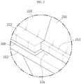
- FIG. 2 is an enlarged view illustrating the area M1 in FIG. 1 .
- the first die lip 112 of the first die 100 and the second die lip 212 of the first die block 210 constituting the second die 200 may be disposed to have a gap equal to the thickness of the shim plate 300 therebetween, thereby forming the opening 12a of the slot through which the coating material is discharged.
- first guide lip 222 of the second die block 220 disposed on one side of the first die block 210 may protrude more than the opening 12a of the slot or the second die lip 212 of the first die block 210 toward the substrate, that is, in the discharge direction of the coating material.
- a first step surface provided due to the difference in protruding length between the first guide lip 222 and the second die lip 212 serves to guide the movement of the coating material discharged through the opening 12a of the slot.
- a second step surface provided due to the difference in protruding length between the second guide lip 232 of the second die block 220 and the second die lip 212 also serves to guide the movement of the coating material discharged through the opening 12a of the slot.
- the first step surface of the first guide lip 222 and the second step surface of the second guide lip 232 may be configured as planes facing each other in parallel.
- the protruding lengths of the first guide lip 222 and the second guide lip 232 may be the same.
- FIG. 3 is an exploded perspective view illustrating the slot die coater 10 shown in FIG. 1 .
- the slot die coater 10 may include a first die 100, die blocks 210, 220, and 230, and a shim plate 300.
- the first die 100 may include the body portion 110 and the support portion 120.
- a first die lip 112 forming the opening 12a of the slot may be provided at the front end of the body portion 110, and an accommodation groove 116 may be provided on the upper surface 114 of the body portion 110 facing the die blocks 210, 220, and 230.
- the accommodation groove 116 may be configured to accommodate the coating material and lead to the slot 12. This accommodation groove 116 may serve as a manifold that delivers the coating material to the slot 12. To this end, the accommodation groove 116 may be configured to be connected to a coating material supply chamber (not shown) installed at the outside through a pipe to receive the coating material from the chamber.
- a coating material supply chamber (not shown) installed at the outside through a pipe to receive the coating material from the chamber.
- the body portion 110 may have a fastening groove 118 through which a predetermined fastening member used to couple the die blocks 210, 220, and 230 and the shim plate 300 to the body portion 110 is fastened.
- the support portion 120 may be configured to extend upwards from the rear end of the body portion 110 so as to support the die blocks 210, 220, and 230.
- the body portion 110 and the support portion 120 may be formed integrally with each other.
- the die blocks 210, 220, and 230 coupled to the first die 100 may be configured to have lower surfaces facing the upper surface 114 of the first die 100, respectively, and to be coupled to the first die 100 to form the accommodation space for accommodate the coating material and the slot 12 for discharging the coating material.
- the first die block 210 may include a second die lip 212 that forms the opening 12a of the slot together with the first die lip 212 of the first die 100.
- the first die block 210 may have an insertion hole 216 into which a fastening member used to couple the first die block 210 to the first die 100 is inserted.
- the second die block 220 may be configured to have a first guide lip 222 among the pair of guide lips 222 and 232 and to be disposed on one side of the first die block 210.
- the second die block 220 may have an insertion hole 226 into which a fastening member used to couple the second die block 220 to the first die 100 is inserted.
- the third die block 230 may be configured to have a second guide lip 232 among the pair of guide lips 222 and 232 and to be disposed on the other side of the first die block 210.
- the third die block 230 may have an insertion hole 236 into which a fastening member used to couple the third die block 230 to the first die 100 is inserted.
- the first die 100 and the die blocks 210, 220, and 230 of the second die 200 may be made of a material including stainless steel.
- the first die 100 and the die blocks 210, 220, and 230 of the second die 200 may be made of a stainless steel material that is easy to process and has high corrosion resistance, such as SUS304, SUS316L, SUS420J2, SUS440C, SUS630, or the like.
- the shim plate 300 may be configured to be interposed between the upper surface of the first die 100 and the lower surfaces of the die blocks 210, 220, and 230 so as to form the slot 12 through which the coating material is discharged.
- the shim plate 300 may determine the shape of the slot 12 through which the coating material is discharged and serve as a gasket that prevents leakage of the coating material to the outside in portions other than the slot 12 of the slot die coater 10.
- the shim plate 300 may have a plate structure that entirely covers the upper surface 114 of the first die 100.
- the shim plate 300 may have a hollow 310 formed in the center thereof so as to correspond to the accommodation groove 116 of the first die 100, and an opening 320 formed on one side thereof so as to lead to the hollow 310.
- This shim plate 300 may determine the shape of the opening 12a of the slot through which the coating material is discharged. That is, the thickness Ts of the shim plate 300 may determine the height of the opening 12a of the slot, and the opening width Ws of the shim plate 300 may determine the width of the opening 12a of the slot.
- the shim plate 300 may have an insertion hole 302 into which a fastening member used to couple the shim plate 300 to the first die 100 is inserted.
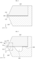
- FIG. 4 is a cross-sectional view taken along line A-A' of the slot die coater 10 shown in FIG. 1 .
- the third die block 230 corresponding to the side portion of the second die 200 may be coupled to the first die 100 with the shim plate 300 interposed therebetween.
- the guide lip 232 of the third die block 230 may protrude toward the substrate (in the X-axis direction).
- the die lip 112 of the first die 100 may protrude by the same length as the guide lip 232 of the third die block 230.
- the die lip 112 of the first die 100 may be configured to protrude by a length shorter than the guide lip 232 of the die block 230.
- the second die block 220 corresponding to the other side portion of the second die 200 may have a structure corresponding to the third die block 230 described above.
- FIG. 5 is a cross-sectional view taken along line B-B' of the slot die coater 10 shown in FIG. 1 .
- the first die block 210 corresponding to the center portion of the second die 200 may be coupled to the first die 100 with the shim plate 300 interposed therebetween so as to form the slot 12 leading to the accommodation groove 116 of the first die 100.
- the rear end of the first die block 210 may be coupled to and supported by the first die 100 with the shim plate 300 interposed therebetween.
- the front end of the first die block 210 may be spaced apart from the first die 100 by a gap corresponding to the thickness of and the shim plate 300, thereby forming the slot 12.
- the die lip 112 of the first die 100 and the die lip 212 of the die block 210 may form the opening 12a of the slot.
- the height of the opening 12a may correspond to the thickness of the shim plate 300
- the width of the opening 12a may correspond to the width of the opening 320 provided in the shim plate 300.
- the movement of the coating material discharged through the opening 12a of the slot formed above may be guided by the guide lips 222 and 232 protruding from both widthwise ends of the opening 12a, respectively.
- FIG. 6 is an enlarged view illustrating the area M2 in FIG. 5 .
- the first die lip 112 provided in the first die 100 and the second die lip 212 provided in the first die block 210 among the die blocks 210, 220, and 230 of the second die 200 may form the opening 12a of the slot through which the coating material is discharged.
- the length L1 of the first die lip 112 may be configured to be greater than the length L2 of the second die lip 212. In another embodiment, the length L1 of the first die lip 112 may be configured to be the same as the length L2 of the second die lip 212.
- the first guide lip 222 of the second die block 220 may have a predetermined thickness and protrude from the opening 12a toward the substrate by a predetermined length Lg. That is, the first guide lip 222 may protrude more than the second die lip 212, which determines the position of the opening 12a, toward the substrate. In other words, the second die lip 212 may be configured to be shorter than the first guide lip 222.
- the length difference (Lg-L2) between the guide lip 222 and the second die lip 212 may be determined in the range of 100 ⁇ m to 300 ⁇ m.
- both side edges of the coating material discharged onto the surface of the target substrate may be mostly exposed to the atmosphere without coming into contact with the first guide lip 222, so the width of the discharged coating material may expand more than the width of the opening 12a and become uneven.
- the length difference (Lg-L2) exceeds 300 ⁇ m, since the opening 12a must be spaced from the target substrate by a certain distance or more to ensure a minimum gap between the first guide lip 222 and the target substrate, it is difficult to control the thickness of the coating layer formed on the target substrate.
- a coating gap refers to the distance between the end of the die lip and the substrate. This coating gap influences the pressure of the coating bead during coating, thereby affecting the coating width. If the coating gap changes, the width of both side edges of the coating material changes until it reaches an equilibrium with atmospheric pressure.
- the coating gap at the end of the first guide lip 222 is smaller than the coating gap at the end of the second die lip 212. Accordingly, the edge portion of the coating material in contact with the first guide lip 222 has a smaller surface area in contact with air and becomes insensitive to pressure changes. As a result, deformation of the edge portion in contact with the first guide lip 222 may be reduced, and uniformity of the overall coating width may be secured.
- the protruding lengths of the first guide lip 222 and the second guide lip 232 may be the same. Therefore, the effect of uniform coating width due to the difference in length between the first guide lip 222 and the second die lip 212 is the same even between the second guide lip 232 and the second die lip 212.
- the first guide lip 222 may be configured to have a length Lg greater than the length L1 of the first die lip 112.
- the length difference (Lg-L2) between the first guide lip 222 and the first die lip 112 may be determined in the range of 100 ⁇ m to 300 ⁇ m.
- FIG. 7 is a cross-sectional view illustrating the lip structure of a slot die coater according to a modified embodiment of the present disclosure.
- the guide lip 222' may have a predetermined thickness Tg and protrude toward the substrate.
- the second die lip 212 may also have a predetermined thickness Td and protrude toward the substrate.
- the guide lip 222' may be configured to be thicker than the second die lip 212.
- the coating material discharged onto the surface of the target substrate through the opening 12a of the slot moves in the thickness direction of the guide lip 222' (e.g., the upward direction in FIG. 7 ) along the target substrate. Accordingly, as the thickness Tg of the guide lip 222' increases, the distance over which the discharged coating material is guided by the guide lip 222' increases. As a result, the effect of the guide lip 222' preventing the discharged coating material from spreading in the width direction (both side directions) and making the edges of the discharged coating material uniform while guiding the movement of the discharged coating material may be further improved.
- FIG. 8 is a diagram illustrating the coating method of a slot die coater according to an embodiment of the present disclosure.
- the coating material C discharged onto the surface of the substrate E through the opening 12a of the slot may expand in the width direction (or the direction of CD) of the substrate E or coating material C, which intersect the movement direction (or the direction of MD) of the substrate E, due to discharge pressure and atmospheric pressure.
- the guide lip 222 may guide the movement of the coating material C according to the movement of the target substrate E while blocking the expansion of the discharged coating material C. Therefore, it is possible to prevent the coating width from changing.
- the coating material C forms a coating bead after being guided by the guide lip 222, instead of spreading immediately after leaving the opening 12a of the slot, it is possible to alleviate sliding in which the edge portions of the coating material collapse and form a gentle boundary surface, and the reproducibility of sliding is also increased.
- the coating material C discharged onto the surface of the target substrate E through the opening 12a of the slot may leak in the opposite direction of the movement direction of the target substrate E due to the discharge pressure and atmospheric pressure.
- This instability in which some of the coating material is lost upstream from the outside of the die lip is referred to as leaking.
- This leaking indicates loss of pre-metered coating material, which makes the final coating thickness unpredictable.
- This leaking may cause the coating material to remain for a long period of time and solidify, or cause a difference in the coating thickness in the width direction.
- the above-described leaking may become worse.
- the first die lip 112 protruding from the opening 12a of the slot toward the substrate E may come into contact with the discharged coating material C to prevent the coating material C from leaking in the opposite direction. Accordingly, it is possible to minimize the occurrence of licking and prevent the coating width from becoming uneven due to pulsation of discharge pressure, and the reproducibility of sliding with respect to the edge portion of the coating material also increases.
- FIG. 9 is a diagram illustrating a coating layer formed by a general slot die coater 20.
- the width Wc1 of the coating material C1 discharged onto the surface of the substrate E through the slot 22 of a general slot die coater 20 expands wider than the opening width Ws1 of the slot 22 due to discharge pressure or atmospheric pressure, bringing about a different result from the design intention.
- the width Wc1 of the coating material C1 is formed non-uniformly depending on the pulsation of the pressure for discharging the coating material C1.
- FIG. 10 is a diagram illustrating a coating layer formed by a slot die coater 10 according to an embodiment of the present disclosure.
- the slot die coater 10 includes a pair of guide lips 222 and 232 that has a predetermined thickness and protrudes from both ends of the opening 12a of the slot toward the substrate E.
- the pair of guide lips 222 and 232 comes into contact with both side edge portions of the coating material C2 discharged onto the surface of the substrate E to block the coating material C2 from expanding in the width direction thereof (or the direction of CD). As a result, the difference between the width Ws2 of the opening 12a of the slot and the width Wc2 of the coating material C2 discharged through the opening 12a may be minimized.
- the pair of guide lips 222 and 232 may guide the movement of the coating material C2 through step surfaces facing each other in parallel, thereby making the edges of the coating material C2 uniform. As a result, it is possible to prevent the width Wc2 of the coating material C2 from becoming uneven due to pulsation of the pressure for discharging the coating material C2.
- the slot die coater 10 may be insensitive to factors that cause changes in coating width, compared to the conventional slot die coater, thereby performing the coating process without a change in the coating width.
- FIG. 11 is a diagram illustrating a second die 200' of a slot die coater according to a modified embodiment of the present disclosure.
- the second die 200' of a slot die coater may include a first die block 210' forming the center portion thereof, and a second die block 220' and a third die block 230' forming side portions thereof.
- the first die block 210' may include a first support protrusion 218a protruding from one side facing the second die block 220' toward the second die block 220', and a second support protrusion 218b protruding from other side facing the third die block 230' toward the third die block 230'.
- the second die block 220' may have a first support groove 228 configured to receive the first support protrusion 218a of the first die block 210' so as to support the first die block 210'.
- the third die block 230' may have a second support groove 238 configured to receive the second support protrusion 218b of the first die block 210' so as to support the first die block 210'.
- the supporting structures 218a, 218b, 228, and 238 supporting the first die block 210' may be provided to maintain the gap between the first die 100 and the first die block 210' of the second die 200' without using additional fastening members, thereby ensuring durability and reliability of the slot die coater even if the slot die coater is manufactured using the second die 200' configured by a combination of die blocks, instead of an integral block.
- FIG. 12 is a diagram illustrating an electrode coating device 400 according to an embodiment of the present disclosure.
- the electrode coating device 400 may be configured to include a slot die coater 10 according to an embodiment of the present disclosure and coat the surface of the electrode substrate using the slot die coater 10.
- the electrode coating device 400 may further include a transfer unit 410, a drying unit 420, and a control unit 430.
- the transfer unit 410 may be configured to transfer an electrode substrate E to be used in electrode manufacturing to the drying unit 420 via the slot die coater 10.
- the transfer unit 410 may include an unwinder 412, a transfer roll 414, a rolling roll 416, and a rewinder 418.
- the unwinder 412 may be configured to unwind and move the electrode substrate E that is generally wound in a roll shape.
- the unwinder 412 may include a wheel on which the electrode substrate E wound in a roll is fixed, and a motor (not shown) that rotates the wheel at a predetermined direction and speed to unwind the electrode substrate E fixed on the wheel.
- the "electrode substrate” may indicate various sheets used in manufacturing electrode assemblies of secondary batteries, such as sheets for manufacturing positive electrodes, sheets for manufacturing negative electrodes, and sheets for manufacturing separators.
- the transfer roll 414 may be configured to be disposed at various positions of the electrode coating device 400 to facilitate movement of the electrode substrate E.
- the rolling roll 416 may be configured to roll the electrode substrate E having a coating layer formed thereon and dried by the drying unit 420.
- the rewinder 418 may be configured to rewind the rolled electrode substrate E.
- the rewinder 418 may include a wheel for rewinding the rolled electrode substrate E and a motor (not shown) that rotates the wheel at a predetermined direction and speed to rewind the rolled electrode substrate E.
- the electrode coating device 400 may be configured to perform a slitting process before transferring the electrode substrate E rolled by the rolling roll 416 to the rewinder 418.
- the slot die coater 10 may apply a coating material onto the surface of the electrode substrate E, which is unwound and transferred by the unwinder 412.
- the drying unit 420 may be configured to dry the electrode substrate E onto which the coating material is applied.
- the drying unit 420 may include a chamber 422 with an internal space, a heating unit 424 that provides hot air to the electrode substrate E, and a lamp 426 that radiates electromagnetic waves in a predetermined wavelength band.
- the lamp 426 may be configured as a MIR (Medium wave Infra-Red) lamp that emits mid-infrared rays in a wavelength band ranging from 1400 nm to 3000 nm.
- MIR Medium wave Infra-Red
- the control unit 430 may be configured to control the overall operation of the electrode coating device 400.
- the control unit 430 may be configured to control the operation of the heating unit 424 and the lamp 426 disposed inside the chamber 422 of the drying unit 420.
- control unit 430 may optionally include hardware such as a general-purpose processor for executing control logic, an Application-Specific Integrated Circuit (ASIC), other chipsets, logic circuits, registers, memory, and the like.
- ASIC Application-Specific Integrated Circuit
- control unit 430 may further include a temperature sensor 432 that measures the temperature inside the chamber 422 and a gas sensor 434 that measures the gas concentration inside the chamber 422.
- control unit 430 may control the operation of the heating unit 424 and the lamp 426 on the basis of temperature information measured by the temperature sensor 432 and gas concentration information measured by the gas sensor 434.
- a pair of guide lips respectively protruding from both widthwise ends of the opening of the slot toward the substrate to be coated may come into contact with both side edge portions of the coating material discharged onto the surface of the substrate to block the coating material from expanding in the side direction of the coating material and to guide the movement of the coating material according to the movement of the substrate, thereby minimizing the phenomenon in which the width of the discharged coating material expands beyond the width of the slot opening due to the discharge pressure or atmospheric pressure and preventing the phenomenon in which the width of the discharged coating material becomes uneven due to pulsation of the discharge pressure.
- a first die lip that earlier meets the substrate moving in one direction may be configured to protrude more toward the substrate than the second die lip that later meets the substrate, thereby preventing the coating material discharged through the slot from leaking in the opposite direction of the movement direction of the substrate due to the discharge pressure or atmospheric pressure.
- the second die having the pair of guide lips may be configured by coupling of a first die block forming the slot together with the first die, a second die block having a first guide lip among the pair of guide lips, and a third die block having a second guide lip among the pair of guide lips, it is possible to easily implement a fine step structure formed between the pair of guide lips and the opening of the slot without precision machining and reduce manufacturing time and manufacturing cost while improving the precision of the slot die coater.
- a support structure may be provided to support the first die block without using additional fastening members so as to maintain the gap between the first die and the first die block of the second die, even if the slot die coater is manufactured using the second die configured as a combination of die blocks, instead of an integrated block, the durability and reliability of the slot die coater may be guaranteed.
Landscapes
- Engineering & Computer Science (AREA)
- Manufacturing & Machinery (AREA)
- Chemical & Material Sciences (AREA)
- Chemical Kinetics & Catalysis (AREA)
- Electrochemistry (AREA)
- General Chemical & Material Sciences (AREA)
- Coating Apparatus (AREA)
- Battery Electrode And Active Subsutance (AREA)
Abstract
Description
- The present application claims priority to
Korean Patent Application No. 10-2022-0092930 filed on July 27, 2022 - The present disclosure relates to a slot die coater and an electrode coating device including the same and, more specifically, relates to a slot die coater that discharges a coating material onto a surface of a substrate through a slot, and an electrode coating device including the same.
- In general, an electrode assembly of a secondary battery capable of being repeatedly charged and discharged is manufactured by stacking or winding multiple layers in a laminated structure in which a separator is interposed between a first electrode corresponding to the positive electrode (cathode) and a second electrode corresponding to the negative electrode (anode). In this case, each electrode is manufactured by applying a slurry coating material containing a positive-electrode active material or a negative-electrode active material onto an electrode substrate made of aluminum or copper and drying the same.
- Recently, slot die coaters have been used in the coating process of this electrode substrate. The slot die coater is a device that discharges a coating material through a slot to coat the surface of a substrate to be coated.
- However, as disclosed in
Korean Unexamined Patent Publication No. 10-2019-0060557 - Moreover, the existing technology has a problem in which the width of the discharged coating material becomes uneven due to the pulsation of pressure applied into the slot die coater.
- The present disclosure is designed to solve the problems of the related art, and therefore the present disclosure is directed to providing a slot die coater capable of preventing a phenomenon in which the width of the coating material discharged onto the surface of the substrate through the slot expands beyond the width of the slot opening due to the discharge pressure and atmospheric pressure and a phenomenon in which the width of the coating material becomes uneven due to the pulsation of discharge pressure, and an electrode coating device including the same.
- A slot die coater according to an embodiment of the present disclosure is a device configured to discharge a coating material onto a surface of a substrate, and may include: a first die having a first surface; a second die having a second surface facing the first surface; and a shim plate interposed between the first surface of the first die and the second surface of the second die to form a slot through which the coating material is discharged, wherein the second die may include a pair of guide lips protruding from both ends of the opening of the slot toward the substrate.
- In an embodiment, the pair of guide lips may be configured to come into contact with both side edge portions of the coating material discharged onto the surface of the substrate so as to guide the movement of the coating material according to the movement of the substrate.
- In an embodiment, the first die may further include an accommodation groove configured to accommodate the coating material and lead to the slot.
- In an embodiment, the first die may include: a body portion having the first surface and the opening located at the front end thereof; and a support portion extending from the rear end of the body portion toward the second die and supporting the second die.
- In an embodiment, the first die may include a first die lip protruding toward the substrate so as to form one side wall of the opening.
- In an embodiment, the second die may further include a second die lip protruding toward the substrate between the pair of guide lips so as to form the other side wall of the opening, and the pair of guide lips may be configured to protrude more than the second die lip toward the substrate.
- In an embodiment, the protruding length of the pair of guide lips toward the substrate may be configured to be greater than that of the second die lip in the range of 100,um to 300µm.
- In an embodiment, the pair of guide lips and the second die lip may be configured to have a predetermined thickness, respectively, and protrude toward the substrate, and the pair of guide lips may be configured to be thicker than the second die lip.
- In an embodiment, the second die may further include a second die lip protruding toward the substrate between the pair of guide lips so as to form the other side wall of the opening, and the first die lip may be configured to protrude more than the second die lip toward the substrate.
- In an embodiment, the second die may include: a first die block disposed at a predetermined gap from the first die so as to form the slot; a second die block having a first guide lip among the pair of guide lips and disposed on one side of the first die block; and a third die block having a second guide lip among the pair of guide lips and disposed on the other side of the first die block, and the first die block may include: a first support protrusion protruding from one side of the first die block facing the second die block toward the second die block; and a second support protrusion protruding from the other side of the first die block facing the third die block toward the third die block, and the second die block may further include a first support groove configured to receive the first support protrusion to support the first die block, and the third die block may further include a second support groove configured to receive the second support protrusion to support the first die block.
- An electrode coating device according to an embodiment of the present disclosure is a device including the slot die coater according to one of the embodiments described above, and may be configured to coat an electrode substrate using the slot die coater.
- According to the present disclosure, a pair of guide lips respectively protruding from both widthwise ends of the opening of the slot toward the substrate to be coated may come into contact with both side edge portions of the coating material discharged onto the surface of the substrate to block the coating material from expanding in the side direction of the coating material and to guide the movement of the coating material according to the movement of the substrate, thereby minimizing the phenomenon in which the width of the discharged coating material expands beyond the width of the slot opening due to the discharge pressure or atmospheric pressure and preventing the phenomenon in which the width of the discharged coating material becomes uneven due to pulsation of the discharge pressure.
- In addition, among the two die lips that form the opening of the slot, a first die lip that earlier meets the substrate moving in one direction may be configured to protrude more toward the substrate than the second die lip that later meets the substrate, thereby preventing the coating material discharged through the slot from leaking in the opposite direction of the movement direction of the substrate due to the discharge pressure or atmospheric pressure.
- In addition, among the first die and the second die constituting the slot die coater, since the second die having the pair of guide lips may be configured by coupling of a first die block forming the slot together with the first die, a second die block having a first guide lip among the pair of guide lips, and a third die block having a second guide lip among the pair of guide lips, it is possible to easily implement a fine step structure formed between the pair of guide lips and the opening of the slot without precision machining and reduce manufacturing time and manufacturing cost while improving the precision of the slot die coater.
- In addition, since a support structure may be provided to support the first die block without using additional fastening members so as to maintain the gap between the first die and the first die block of the second die, even if the slot die coater is manufactured using the second die configured as a combination of die blocks, instead of an integrated block, the durability and reliability of the slot die coater is able to be guaranteed.
- Furthermore, those skilled in the art to which the present disclosure pertains will be able to clearly understand from the following description that various embodiments according to the present disclosure can solve various technical problems not mentioned above.
-
-
FIG. 1 is a perspective view illustrating a slot die coater according to an embodiment of the present disclosure. -
FIG. 2 is an enlarged view illustrating the area M1 inFIG. 1 . -
FIG. 3 is an exploded perspective view illustrating the slot die coater shown inFIG. 1 . -
FIG. 4 is a cross-sectional view taken along line A-A' of the slot die coater shown inFIG. 1 . -
FIG. 5 is a cross-sectional view taken along line B-B' of the slot die coater shown inFIG. 1 . -
FIG. 6 is an enlarged view illustrating the area M2 inFIG. 5 . -
FIG. 7 is a cross-sectional view illustrating the lip structure of a slot die coater according to a modified embodiment of the present disclosure. -
FIG. 8 is a diagram illustrating the coating method of a slot die coater according to an embodiment of the present disclosure. -
FIG. 9 is a diagram illustrating a coating layer formed by a general slot die coater. -
FIG. 10 is a diagram illustrating a coating layer formed by a slot die coater according to an embodiment of the present disclosure. -
FIG. 11 is a diagram illustrating a second die of a slot die coater according to a modified embodiment of the present disclosure. -
FIG. 12 is a diagram illustrating an electrode coating device according to an embodiment of the present disclosure. - Hereinafter, embodiments according to the present disclosure will be described in detail with reference to the accompanying drawings to clarify solutions corresponding to the technical problems of the present disclosure. However, in describing the present disclosure, a description of related known technology, which may obscure the subject matter of the present disclosure, may be omitted. In addition, the terms used in this specification are defined in consideration of the functions in the present disclosure and may vary depending on the intention of the designer, manufacturer, etc. or custom thereof. Therefore, definitions of the terms described below should be made based on the description throughout this specification.
- Meanwhile, the same reference numerals indicate the same components in the attached drawings. In addition, the components of the present disclosure or parts of each component shown in the attached drawings may be exaggerated, reduced, or simplified in order to effectively explain the technical features of the present disclosure.
-
FIG. 1 is a perspective view illustrating aslot die coater 10 according to an embodiment of the present disclosure. - As shown in
FIG. 1 , theslot die coater 10 according to an embodiment of the present disclosure may be configured to discharge a coating material through aslot 12 to the transfer path of a target substrate transferred in one direction by a predetermined transfer means so as to coat the surface of the target substrate. To this end, theslot die coater 10 may include afirst die 100, asecond die 200, and ashim plate 300. - The
first die 100 may be configured to have a first surface facing thesecond die 200 and to be combined with thesecond die 200 to form an accommodation space for accommodating a coating material. - In this case, the
first die 100 may include abody portion 110 that has the first surface and an opening 12a of the slot located at the front end thereof, and asupport portion 120 that extends from the rear end of thebody portion 110 toward thesecond die 200 so as to support thesecond die 200. In addition, thebody portion 110 of thefirst die 100 may have afirst die lip 112 that protrudes toward the target substrate (X-axis direction) and forms one side wall of the opening 12a. - The opening 12a located at the end of the
slot 12 may have a predetermined height and width, but may have a width considerably greater than its height. As will be described again below, the width of the opening 12a located at the end of theslot 12 may correspond to the width of a coating layer formed on the surface of the substrate. - The
second die 200 may be configured to have a second surface facing the first surface of thefirst die 100 and to be combined with thefirst die 100 to form the accommodation space for accommodating the coating material. - In addition, the
second die 200 may have a pair ofguide lips - The pair of
guide lips - In addition, the
second die 200 may include asecond die lip 212 that protrudes toward the target substrate (X-axis direction) between the pair ofguide lips - In this case, the pair of
guide lips second die lip 212 toward the target substrate. As will be described again below, the protruding length of the pair ofguide lips second die lip 212 in the range of 100,um to 300µm. - In addition, the
first die lip 112 of thefirst die 100 may be configured to protrude more than thesecond die lip 212 toward the target substrate. In this case, the protruding length of thefirst die lip 112 toward the target substrate may be configured to be greater than that of thesecond die lip 212 in the range of 100µm to 300µm. Depending on the embodiment, thefirst die lip 112 may be configured to protrude by the same length as thesecond die lip 212. - In an embodiment, the
second die 200 may include afirst die block 210, asecond die block 220, and athird die block 230. Thesecond die 200 may be formed by coupling of thefirst die block 210, thesecond die block 220, and thethird die block 230. That is, thesecond die 200 may be configured by coupling three dieblocks opening 12a. - In this case, the
first die block 210 may include thesecond die lip 212 and may be configured to be disposed at a certain gap from thefirst die 100 to form theslot 12. - The
second die block 220 may include thefirst guide lip 222 among the pair ofguide lips first die block 210. - The
third die block 230 may include thesecond guide lip 232 among the pair ofguide lips first die block 210. - The
first die block 210, thesecond die block 220, and thethird die block 230 may be configured to be coupled to thefirst die 100 by fasteningmembers - As described above, since the
second die 200 constituting the slot diecoater 10 may be configured by coupling of the die blocks 210, 220, and 230 each having only one of the guide lip and die lip, it is possible to easily implement a fine step structure formed between the pair ofguide lips second die lip 212 without precision machining and reduce manufacturing time and manufacturing cost while improving the precision of the slot die coater. - As will be described again below, the
shim plate 300 may be configured to be interposed between the first surface of thefirst die 100 and the second surface of thesecond die 200 so as to form theslot 12 through which the coating material is discharged. - Meanwhile, the substrate to be coated by the slot die
coater 10 may be an electrode substrate used in manufacturing electrodes of secondary batteries. In this case, the electrode substrate may be a metal foil used in manufacturing the positive or negative electrode, or a sheet of PE (polyethylene) or PP (polypropylene) used in manufacturing a separator. - In addition, the coating material discharged from the slot die
coater 10 may be a slurry containing a conductive agent and a binder along with a positive-electrode active material or negative-electrode active material, or may be a coating material containing a ceramic material. In this case, materials such as LiCoO2, LiMn2O4, LiFePO4, LiNiCoAlO2, LiNiMnCoO2, or Li2TiO3 may be used as the positive-electrode active material. In addition, materials such as natural graphite, artificial graphite, or low-crystalline carbon may be used as the negative-electrode active material. -
FIG. 2 is an enlarged view illustrating the area M1 inFIG. 1 . - As shown in
FIG. 2 , thefirst die lip 112 of thefirst die 100 and thesecond die lip 212 of thefirst die block 210 constituting thesecond die 200 may be disposed to have a gap equal to the thickness of theshim plate 300 therebetween, thereby forming theopening 12a of the slot through which the coating material is discharged. - In addition, the
first guide lip 222 of thesecond die block 220 disposed on one side of thefirst die block 210 may protrude more than theopening 12a of the slot or thesecond die lip 212 of thefirst die block 210 toward the substrate, that is, in the discharge direction of the coating material. - A first step surface provided due to the difference in protruding length between the
first guide lip 222 and thesecond die lip 212 serves to guide the movement of the coating material discharged through theopening 12a of the slot. - Likewise, a second step surface provided due to the difference in protruding length between the
second guide lip 232 of thesecond die block 220 and thesecond die lip 212 also serves to guide the movement of the coating material discharged through theopening 12a of the slot. In this case, the first step surface of thefirst guide lip 222 and the second step surface of thesecond guide lip 232 may be configured as planes facing each other in parallel. - In addition, the protruding lengths of the
first guide lip 222 and thesecond guide lip 232 may be the same. -
FIG. 3 is an exploded perspective view illustrating the slot diecoater 10 shown inFIG. 1 . - As shown in
FIG. 3 , the slot diecoater 10 may include afirst die 100, dieblocks shim plate 300. - As described above, the
first die 100 may include thebody portion 110 and thesupport portion 120. Afirst die lip 112 forming theopening 12a of the slot may be provided at the front end of thebody portion 110, and anaccommodation groove 116 may be provided on theupper surface 114 of thebody portion 110 facing the die blocks 210, 220, and 230. - The
accommodation groove 116 may be configured to accommodate the coating material and lead to theslot 12. Thisaccommodation groove 116 may serve as a manifold that delivers the coating material to theslot 12. To this end, theaccommodation groove 116 may be configured to be connected to a coating material supply chamber (not shown) installed at the outside through a pipe to receive the coating material from the chamber. - Depending on the embodiment, the
body portion 110 may have afastening groove 118 through which a predetermined fastening member used to couple the die blocks 210, 220, and 230 and theshim plate 300 to thebody portion 110 is fastened. - The
support portion 120 may be configured to extend upwards from the rear end of thebody portion 110 so as to support the die blocks 210, 220, and 230. In this case, thebody portion 110 and thesupport portion 120 may be formed integrally with each other. - The die blocks 210, 220, and 230 coupled to the
first die 100 may be configured to have lower surfaces facing theupper surface 114 of thefirst die 100, respectively, and to be coupled to thefirst die 100 to form the accommodation space for accommodate the coating material and theslot 12 for discharging the coating material. - To this end, the
first die block 210 may include asecond die lip 212 that forms theopening 12a of the slot together with thefirst die lip 212 of thefirst die 100. Depending on the embodiment, thefirst die block 210 may have aninsertion hole 216 into which a fastening member used to couple thefirst die block 210 to thefirst die 100 is inserted. - In addition, the
second die block 220 may be configured to have afirst guide lip 222 among the pair ofguide lips first die block 210. Depending on the embodiment, thesecond die block 220 may have aninsertion hole 226 into which a fastening member used to couple thesecond die block 220 to thefirst die 100 is inserted. - The
third die block 230 may be configured to have asecond guide lip 232 among the pair ofguide lips first die block 210. Depending on the embodiment, thethird die block 230 may have aninsertion hole 236 into which a fastening member used to couple thethird die block 230 to thefirst die 100 is inserted. - The
first die 100 and the die blocks 210, 220, and 230 of thesecond die 200 may be made of a material including stainless steel. For example, thefirst die 100 and the die blocks 210, 220, and 230 of thesecond die 200 may be made of a stainless steel material that is easy to process and has high corrosion resistance, such as SUS304, SUS316L, SUS420J2, SUS440C, SUS630, or the like. - The
shim plate 300 may be configured to be interposed between the upper surface of thefirst die 100 and the lower surfaces of the die blocks 210, 220, and 230 so as to form theslot 12 through which the coating material is discharged. Theshim plate 300 may determine the shape of theslot 12 through which the coating material is discharged and serve as a gasket that prevents leakage of the coating material to the outside in portions other than theslot 12 of the slot diecoater 10. - To this end, the
shim plate 300 may have a plate structure that entirely covers theupper surface 114 of thefirst die 100. In addition, theshim plate 300 may have a hollow 310 formed in the center thereof so as to correspond to theaccommodation groove 116 of thefirst die 100, and anopening 320 formed on one side thereof so as to lead to the hollow 310. - This
shim plate 300 may determine the shape of theopening 12a of the slot through which the coating material is discharged. That is, the thickness Ts of theshim plate 300 may determine the height of theopening 12a of the slot, and the opening width Ws of theshim plate 300 may determine the width of theopening 12a of the slot. - Depending on the embodiment, the
shim plate 300 may have aninsertion hole 302 into which a fastening member used to couple theshim plate 300 to thefirst die 100 is inserted. -
FIG. 4 is a cross-sectional view taken along line A-A' of the slot diecoater 10 shown inFIG. 1 . - As shown in
FIG. 4 , thethird die block 230 corresponding to the side portion of thesecond die 200 may be coupled to thefirst die 100 with theshim plate 300 interposed therebetween. Theguide lip 232 of thethird die block 230 may protrude toward the substrate (in the X-axis direction). In this case, thedie lip 112 of thefirst die 100 may protrude by the same length as theguide lip 232 of thethird die block 230. - Depending on the embodiment, the
die lip 112 of thefirst die 100 may be configured to protrude by a length shorter than theguide lip 232 of thedie block 230. - The
second die block 220 corresponding to the other side portion of thesecond die 200 may have a structure corresponding to thethird die block 230 described above. -
FIG. 5 is a cross-sectional view taken along line B-B' of the slot diecoater 10 shown inFIG. 1 . - As shown in
FIG. 5 , thefirst die block 210 corresponding to the center portion of thesecond die 200 may be coupled to thefirst die 100 with theshim plate 300 interposed therebetween so as to form theslot 12 leading to theaccommodation groove 116 of thefirst die 100. - That is, the rear end of the
first die block 210 may be coupled to and supported by thefirst die 100 with theshim plate 300 interposed therebetween. On the other hand, the front end of thefirst die block 210 may be spaced apart from thefirst die 100 by a gap corresponding to the thickness of and theshim plate 300, thereby forming theslot 12. - Meanwhile, the
die lip 112 of thefirst die 100 and thedie lip 212 of thedie block 210 may form theopening 12a of the slot. As described above, the height of theopening 12a may correspond to the thickness of theshim plate 300, and the width of theopening 12a may correspond to the width of theopening 320 provided in theshim plate 300. - The movement of the coating material discharged through the
opening 12a of the slot formed above may be guided by theguide lips opening 12a, respectively. -
FIG. 6 is an enlarged view illustrating the area M2 inFIG. 5 . - As shown in
FIG. 6 , thefirst die lip 112 provided in thefirst die 100 and thesecond die lip 212 provided in thefirst die block 210 among the die blocks 210, 220, and 230 of thesecond die 200 may form theopening 12a of the slot through which the coating material is discharged. - In this case, the length L1 of the
first die lip 112 may be configured to be greater than the length L2 of thesecond die lip 212. In another embodiment, the length L1 of thefirst die lip 112 may be configured to be the same as the length L2 of thesecond die lip 212. - Meanwhile, the
first guide lip 222 of thesecond die block 220 may have a predetermined thickness and protrude from theopening 12a toward the substrate by a predetermined length Lg. That is, thefirst guide lip 222 may protrude more than thesecond die lip 212, which determines the position of theopening 12a, toward the substrate. In other words, thesecond die lip 212 may be configured to be shorter than thefirst guide lip 222. - In this case, the length difference (Lg-L2) between the
guide lip 222 and thesecond die lip 212 may be determined in the range of 100µm to 300µm. - If the length difference (Lg-L2) is less than 100,um, both side edges of the coating material discharged onto the surface of the target substrate may be mostly exposed to the atmosphere without coming into contact with the
first guide lip 222, so the width of the discharged coating material may expand more than the width of theopening 12a and become uneven. - On the other hand, if the length difference (Lg-L2) exceeds 300µm, since the
opening 12a must be spaced from the target substrate by a certain distance or more to ensure a minimum gap between thefirst guide lip 222 and the target substrate, it is difficult to control the thickness of the coating layer formed on the target substrate. - A coating gap refers to the distance between the end of the die lip and the substrate. This coating gap influences the pressure of the coating bead during coating, thereby affecting the coating width. If the coating gap changes, the width of both side edges of the coating material changes until it reaches an equilibrium with atmospheric pressure.
- In the present disclosure, since the
second die lip 212 is shorter than thefirst guide lip 222, the coating gap at the end of thefirst guide lip 222 is smaller than the coating gap at the end of thesecond die lip 212. Accordingly, the edge portion of the coating material in contact with thefirst guide lip 222 has a smaller surface area in contact with air and becomes insensitive to pressure changes. As a result, deformation of the edge portion in contact with thefirst guide lip 222 may be reduced, and uniformity of the overall coating width may be secured. - The protruding lengths of the
first guide lip 222 and thesecond guide lip 232 may be the same. Therefore, the effect of uniform coating width due to the difference in length between thefirst guide lip 222 and thesecond die lip 212 is the same even between thesecond guide lip 232 and thesecond die lip 212. - Meanwhile, although the length Lg of the
first guide lip 222 and the length L1 of thefirst die lip 112 are illustrated as being the same or similar to each other inFIG. 6 , depending on the embodiment, thefirst guide lip 222 may be configured to have a length Lg greater than the length L1 of thefirst die lip 112. In this case, the length difference (Lg-L2) between thefirst guide lip 222 and thefirst die lip 112 may be determined in the range of 100µm to 300µm. -
FIG. 7 is a cross-sectional view illustrating the lip structure of a slot die coater according to a modified embodiment of the present disclosure. - As shown in
FIG. 7 , the guide lip 222' may have a predetermined thickness Tg and protrude toward the substrate. In addition, thesecond die lip 212 may also have a predetermined thickness Td and protrude toward the substrate. In this case, the guide lip 222' may be configured to be thicker than thesecond die lip 212. - As will be described again below, the coating material discharged onto the surface of the target substrate through the
opening 12a of the slot moves in the thickness direction of the guide lip 222' (e.g., the upward direction inFIG. 7 ) along the target substrate. Accordingly, as the thickness Tg of the guide lip 222' increases, the distance over which the discharged coating material is guided by the guide lip 222' increases. As a result, the effect of the guide lip 222' preventing the discharged coating material from spreading in the width direction (both side directions) and making the edges of the discharged coating material uniform while guiding the movement of the discharged coating material may be further improved. -
FIG. 8 is a diagram illustrating the coating method of a slot die coater according to an embodiment of the present disclosure. - As shown in
FIG. 8 , the coating material C discharged onto the surface of the substrate E through theopening 12a of the slot may expand in the width direction (or the direction of CD) of the substrate E or coating material C, which intersect the movement direction (or the direction of MD) of the substrate E, due to discharge pressure and atmospheric pressure. - In this case, the
guide lip 222 may guide the movement of the coating material C according to the movement of the target substrate E while blocking the expansion of the discharged coating material C. Therefore, it is possible to prevent the coating width from changing. In addition, since the coating material C forms a coating bead after being guided by theguide lip 222, instead of spreading immediately after leaving theopening 12a of the slot, it is possible to alleviate sliding in which the edge portions of the coating material collapse and form a gentle boundary surface, and the reproducibility of sliding is also increased. - Meanwhile, the coating material C discharged onto the surface of the target substrate E through the
opening 12a of the slot may leak in the opposite direction of the movement direction of the target substrate E due to the discharge pressure and atmospheric pressure. This instability in which some of the coating material is lost upstream from the outside of the die lip is referred to as leaking. This leaking indicates loss of pre-metered coating material, which makes the final coating thickness unpredictable. This leaking may cause the coating material to remain for a long period of time and solidify, or cause a difference in the coating thickness in the width direction. In particular, when the coating material is ejected at high pressure for the purpose of thin film coating or in the state in which the coating gap is lowered to hundreds of µm to reduce the thickness difference in the width direction of the coating layer, the above-described leaking may become worse. - In this case, the
first die lip 112 protruding from theopening 12a of the slot toward the substrate E may come into contact with the discharged coating material C to prevent the coating material C from leaking in the opposite direction. Accordingly, it is possible to minimize the occurrence of licking and prevent the coating width from becoming uneven due to pulsation of discharge pressure, and the reproducibility of sliding with respect to the edge portion of the coating material also increases. -
FIG. 9 is a diagram illustrating a coating layer formed by a general slot die coater 20. - As shown in
FIG. 9 , the width Wc1 of the coating material C1 discharged onto the surface of the substrate E through theslot 22 of a general slot die coater 20 expands wider than the opening width Ws1 of theslot 22 due to discharge pressure or atmospheric pressure, bringing about a different result from the design intention. - Moreover, the width Wc1 of the coating material C1 is formed non-uniformly depending on the pulsation of the pressure for discharging the coating material C1.
-
FIG. 10 is a diagram illustrating a coating layer formed by aslot die coater 10 according to an embodiment of the present disclosure. - As shown in
FIG. 10 , the slot diecoater 10 according to an embodiment of the present disclosure includes a pair ofguide lips opening 12a of the slot toward the substrate E. - The pair of
guide lips opening 12a of the slot and the width Wc2 of the coating material C2 discharged through theopening 12a may be minimized. - In addition, the pair of
guide lips - As described above, the slot die
coater 10 according to the present disclosure may be insensitive to factors that cause changes in coating width, compared to the conventional slot die coater, thereby performing the coating process without a change in the coating width. -
FIG. 11 is a diagram illustrating a second die 200' of a slot die coater according to a modified embodiment of the present disclosure. - As shown in
FIG. 11 , the second die 200' of a slot die coater according to a modified embodiment of the present disclosure may include a first die block 210' forming the center portion thereof, and a second die block 220' and a third die block 230' forming side portions thereof. - In this case, the first die block 210' may include a
first support protrusion 218a protruding from one side facing the second die block 220' toward the second die block 220', and asecond support protrusion 218b protruding from other side facing the third die block 230' toward the third die block 230'. - The second die block 220' may have a
first support groove 228 configured to receive thefirst support protrusion 218a of the first die block 210' so as to support the first die block 210'. - The third die block 230' may have a
second support groove 238 configured to receive thesecond support protrusion 218b of the first die block 210' so as to support the first die block 210'. - As described above, the supporting
structures first die 100 and the first die block 210' of the second die 200' without using additional fastening members, thereby ensuring durability and reliability of the slot die coater even if the slot die coater is manufactured using the second die 200' configured by a combination of die blocks, instead of an integral block. -
FIG. 12 is a diagram illustrating anelectrode coating device 400 according to an embodiment of the present disclosure. - As shown in
FIG. 12 , theelectrode coating device 400 may be configured to include aslot die coater 10 according to an embodiment of the present disclosure and coat the surface of the electrode substrate using the slot diecoater 10. - To this end, the
electrode coating device 400 may further include atransfer unit 410, adrying unit 420, and acontrol unit 430. - The
transfer unit 410 may be configured to transfer an electrode substrate E to be used in electrode manufacturing to thedrying unit 420 via the slot diecoater 10. To this end, thetransfer unit 410 may include anunwinder 412, atransfer roll 414, a rollingroll 416, and arewinder 418. - The
unwinder 412 may be configured to unwind and move the electrode substrate E that is generally wound in a roll shape. In this case, theunwinder 412 may include a wheel on which the electrode substrate E wound in a roll is fixed, and a motor (not shown) that rotates the wheel at a predetermined direction and speed to unwind the electrode substrate E fixed on the wheel. In this specification, the "electrode substrate" may indicate various sheets used in manufacturing electrode assemblies of secondary batteries, such as sheets for manufacturing positive electrodes, sheets for manufacturing negative electrodes, and sheets for manufacturing separators. - The
transfer roll 414 may be configured to be disposed at various positions of theelectrode coating device 400 to facilitate movement of the electrode substrate E. - The rolling
roll 416 may be configured to roll the electrode substrate E having a coating layer formed thereon and dried by the dryingunit 420. - The
rewinder 418 may be configured to rewind the rolled electrode substrate E. To this end, therewinder 418 may include a wheel for rewinding the rolled electrode substrate E and a motor (not shown) that rotates the wheel at a predetermined direction and speed to rewind the rolled electrode substrate E. - Depending on the embodiment, the
electrode coating device 400 may be configured to perform a slitting process before transferring the electrode substrate E rolled by the rollingroll 416 to therewinder 418. - Meanwhile, the slot die
coater 10 may apply a coating material onto the surface of the electrode substrate E, which is unwound and transferred by theunwinder 412. - The drying
unit 420 may be configured to dry the electrode substrate E onto which the coating material is applied. - To this end, the drying
unit 420 may include achamber 422 with an internal space, aheating unit 424 that provides hot air to the electrode substrate E, and alamp 426 that radiates electromagnetic waves in a predetermined wavelength band. In this case, thelamp 426 may be configured as a MIR (Medium wave Infra-Red) lamp that emits mid-infrared rays in a wavelength band ranging from 1400 nm to 3000 nm. - The
control unit 430 may be configured to control the overall operation of theelectrode coating device 400. In particular, thecontrol unit 430 may be configured to control the operation of theheating unit 424 and thelamp 426 disposed inside thechamber 422 of thedrying unit 420. - To this end, the
control unit 430 may optionally include hardware such as a general-purpose processor for executing control logic, an Application-Specific Integrated Circuit (ASIC), other chipsets, logic circuits, registers, memory, and the like. - In addition, the
control unit 430 may further include atemperature sensor 432 that measures the temperature inside thechamber 422 and agas sensor 434 that measures the gas concentration inside thechamber 422. In this case, thecontrol unit 430 may control the operation of theheating unit 424 and thelamp 426 on the basis of temperature information measured by thetemperature sensor 432 and gas concentration information measured by thegas sensor 434. - As described above, according to the present disclosure, a pair of guide lips respectively protruding from both widthwise ends of the opening of the slot toward the substrate to be coated may come into contact with both side edge portions of the coating material discharged onto the surface of the substrate to block the coating material from expanding in the side direction of the coating material and to guide the movement of the coating material according to the movement of the substrate, thereby minimizing the phenomenon in which the width of the discharged coating material expands beyond the width of the slot opening due to the discharge pressure or atmospheric pressure and preventing the phenomenon in which the width of the discharged coating material becomes uneven due to pulsation of the discharge pressure.
- In addition, among the two die lips that form the opening of the slot, a first die lip that earlier meets the substrate moving in one direction may be configured to protrude more toward the substrate than the second die lip that later meets the substrate, thereby preventing the coating material discharged through the slot from leaking in the opposite direction of the movement direction of the substrate due to the discharge pressure or atmospheric pressure.
- In addition, among the first die and the second die constituting the slot die coater, since the second die having the pair of guide lips may be configured by coupling of a first die block forming the slot together with the first die, a second die block having a first guide lip among the pair of guide lips, and a third die block having a second guide lip among the pair of guide lips, it is possible to easily implement a fine step structure formed between the pair of guide lips and the opening of the slot without precision machining and reduce manufacturing time and manufacturing cost while improving the precision of the slot die coater.
- In addition, since a support structure may be provided to support the first die block without using additional fastening members so as to maintain the gap between the first die and the first die block of the second die, even if the slot die coater is manufactured using the second die configured as a combination of die blocks, instead of an integrated block, the durability and reliability of the slot die coater may be guaranteed.
- Furthermore, it goes without saying that the embodiments according to the present disclosure are able to solve various technical problems other than those mentioned in this specification in the relevant technical fields as well as this technical field.
- So far, the present disclosure has been described with reference to specific embodiments. However, those skilled in the art will clearly understand that various modified embodiments may be implemented within the technical scope of the present disclosure. Therefore, the previously disclosed embodiments should be considered as those intended to describe the present disclosure, instead of those intended to limit the present disclosure. In other words, the true scope of the technical idea of the present disclosure is shown in the claims, and all differences within the scope equivalent thereto should be construed as being included in the present disclosure.
Claims (12)
- A slot die coater configured to discharge a coating material onto a surface of a substrate, the slot die coater comprising:a first die having a first surface;a second die having a second surface facing the first surface; anda shim plate interposed between the first surface of the first die and the second surface of the second die to form a slot through which the coating material is discharged,wherein the second die comprises a pair of guide lips protruding from both ends of the opening of the slot toward the substrate.
- The slot die coater according to claim 1,
wherein the pair of guide lips is configured to come into contact with both side edge portions of the coating material discharged onto the surface of the substrate so as to guide the movement of the coating material according to the movement of the substrate. - The slot die coater according to claim 1,
wherein the first die further comprises an accommodation groove configured to accommodate the coating material and lead to the slot. - The slot die coater according to claim 1,
wherein the first die comprises:a body portion having the first surface and the opening located at the front end thereof; anda support portion extending from the rear end of the body portion toward the second die and supporting the second die. - The slot die coater according to claim 1,
wherein the first die comprises a first die lip protruding toward the substrate so as to form one side wall of the opening. - The slot die coater according to claim 1,wherein the second die further comprises a second die lip protruding toward the substrate between the pair of guide lips so as to form one side wall of the opening, andwherein the pair of guide lips is configured to protrude more than the second die lip toward the substrate.
- The slot die coater according to claim 6,
wherein the protruding length of the pair of guide lips toward the substrate is configured to be greater than that of the second die lip in the range of 100µm to 300µm. - The slot die coater according to claim 6,wherein the pair of guide lips and the second die lip are configured to have a predetermined thickness, respectively, and protrude toward the substrate, andwherein the pair of guide lips is configured to be thicker than the second die lip.
- The slot die coater according to claim 5,
wherein the second die further comprisesa second die lip protruding toward the substrate between the pair of guide lips so as to form the other side wall of the opening, andwherein the first die lip is configured to protrude more than the second die lip toward the substrate. - The slot die coater according to claim 1,
wherein the second die comprises:a first die block disposed at a predetermined gap from the first die so as to form the slot;a second die block having a first guide lip among the pair of guide lips and disposed on one side of the first die block; anda third die block having a second guide lip among the pair of guide lips and disposed on the other side of the first die block. - The slot die coater according to claim 10,
wherein the first die block comprises:a first support protrusion protruding from one side of the first die block facing the second die block toward the second die block; anda second support protrusion protruding from the other side of the first die block facing the third die block toward the third die block,wherein the second die block further comprises a first support groove configured to receive the first support protrusion to support the first die block,wherein the third die block further comprises a second support groove configured to receive the second support protrusion to support the first die block. - An electrode coating device comprising the slot die coater according to any one of claims 1 to 11, configured to coat an electrode substrate using the slot die coater.
Applications Claiming Priority (2)
| Application Number | Priority Date | Filing Date | Title |
|---|---|---|---|
| KR1020220092930A KR102936588B1 (en) | 2022-07-27 | 2022-07-27 | Slot die coater and electrode coating device including same |
| PCT/KR2023/009976 WO2024025219A1 (en) | 2022-07-27 | 2023-07-12 | Slot die coater and electrode coating device including same |
Publications (3)
| Publication Number | Publication Date |
|---|---|
| EP4391100A1 true EP4391100A1 (en) | 2024-06-26 |
| EP4391100A4 EP4391100A4 (en) | 2025-02-12 |
| EP4391100B1 EP4391100B1 (en) | 2026-02-18 |
Family
ID=89706806
Family Applications (1)
| Application Number | Title | Priority Date | Filing Date |
|---|---|---|---|
| EP23846878.9A Active EP4391100B1 (en) | 2022-07-27 | 2023-07-12 | Slot die coater and electrode coating device including same |
Country Status (7)
| Country | Link |
|---|---|
| US (1) | US20250091083A1 (en) |
| EP (1) | EP4391100B1 (en) |
| JP (1) | JP7806231B2 (en) |
| KR (1) | KR102936588B1 (en) |
| CN (1) | CN117897823A (en) |
| ES (1) | ES3064322T3 (en) |
| WO (1) | WO2024025219A1 (en) |
Families Citing this family (6)
| Publication number | Priority date | Publication date | Assignee | Title |
|---|---|---|---|---|
| KR20220094459A (en) * | 2020-12-29 | 2022-07-06 | 주식회사 엘지에너지솔루션 | Dual slot die coater |
| EP4260949B1 (en) * | 2021-11-29 | 2025-12-24 | LG Energy Solution, Ltd. | Dual slot die coater |
| KR102947414B1 (en) | 2024-01-31 | 2026-04-01 | 주식회사 엘지에너지솔루션 | Apparatus and method for diagnosing battery |
| KR20250144682A (en) * | 2024-03-27 | 2025-10-13 | 주식회사 엘지에너지솔루션 | Slot die device |
| CN118080223B (en) * | 2024-04-28 | 2024-06-21 | 常州市芳烨印铁制罐有限公司 | Metal material coating equipment and coating method |
| KR20250176020A (en) * | 2024-06-11 | 2025-12-18 | 주식회사 엘지에너지솔루션 | Coating apparatus |
Family Cites Families (10)
| Publication number | Priority date | Publication date | Assignee | Title |
|---|---|---|---|---|
| JP2001327906A (en) * | 2000-05-24 | 2001-11-27 | Matsushita Electric Ind Co Ltd | Stripe coating equipment |
| KR101057359B1 (en) | 2009-12-18 | 2011-08-17 | 주식회사 나래나노텍 | A Device and A Method of Preventing Flowing of Coating Liquid for Slit Die, and A Slit Die and A Coating Apparatus Having the Same |
| JP2013208600A (en) | 2012-03-30 | 2013-10-10 | Toppan Printing Co Ltd | Coating apparatus |
| KR101750326B1 (en) * | 2012-12-07 | 2017-06-23 | 주식회사 엘지화학 | Improved slot die for chamber structure and coating apparatus having the same |
| JP2015136675A (en) * | 2014-01-24 | 2015-07-30 | Necエナジーデバイス株式会社 | Coating apparatus, assembly method of coating apparatus, and manufacturing method of electrode for secondary battery |
| KR102248306B1 (en) * | 2017-07-13 | 2021-05-03 | 주식회사 엘지화학 | Coating Apparatus |
| KR101990704B1 (en) | 2017-11-24 | 2019-06-18 | 고려대학교 산학협력단 | Slot coating equipment with improved coating bead region |
| KR102048775B1 (en) * | 2017-12-29 | 2019-11-26 | 한국기술교육대학교 산학협력단 | A multi-way array slot die head for pixel coating and a coating method using it |
| KR102362174B1 (en) * | 2018-10-01 | 2022-02-10 | 주식회사 엘지에너지솔루션 | Slot die coater adjusting device for adjusting the distance between the upper discharge port and the lower discharge port of the slot die coater and Electrode active material coating system comprising the same |
| WO2021217617A1 (en) | 2020-04-30 | 2021-11-04 | 宁德时代新能源科技股份有限公司 | Negative electrode active material, manufacturing method therefor, secondary battery, and device comprising secondary battery |
-
2022
- 2022-07-27 KR KR1020220092930A patent/KR102936588B1/en active Active
-
2023
- 2023-07-12 US US18/291,480 patent/US20250091083A1/en active Pending
- 2023-07-12 JP JP2024521164A patent/JP7806231B2/en active Active
- 2023-07-12 ES ES23846878T patent/ES3064322T3/en active Active
- 2023-07-12 WO PCT/KR2023/009976 patent/WO2024025219A1/en not_active Ceased
- 2023-07-12 EP EP23846878.9A patent/EP4391100B1/en active Active
- 2023-07-12 CN CN202380013287.9A patent/CN117897823A/en active Pending
Also Published As
| Publication number | Publication date |
|---|---|
| JP2024535544A (en) | 2024-09-30 |
| EP4391100A4 (en) | 2025-02-12 |
| KR102936588B1 (en) | 2026-03-06 |
| JP7806231B2 (en) | 2026-01-26 |
| KR20240015281A (en) | 2024-02-05 |
| WO2024025219A1 (en) | 2024-02-01 |
| EP4391100B1 (en) | 2026-02-18 |
| CN117897823A (en) | 2024-04-16 |
| US20250091083A1 (en) | 2025-03-20 |
| ES3064322T3 (en) | 2026-04-23 |
Similar Documents
| Publication | Publication Date | Title |
|---|---|---|
| EP4391100B1 (en) | Slot die coater and electrode coating device including same | |
| US20240066547A1 (en) | Coating die, coating device, coating method, and method for manufacturing secondary cell | |
| US20230361358A1 (en) | Battery | |
| US9067229B2 (en) | Active material coating apparatus and coating method using the same | |
| EP4272878B1 (en) | Slot die shim and slot die including same | |
| US12132189B2 (en) | System and method for manufacturing positive electrode for secondary battery | |
| EP4243109B1 (en) | Die coater shim and die coater for coating active material on current collector for secondary battery | |
| JP7566152B2 (en) | Dual Slot Die Coater | |
| US20190103598A1 (en) | Method of manufacturing battery electrode and electrode manufacturing apparatus | |
| JP7842904B2 (en) | Method for manufacturing ribbon-shaped electrodes and device therefor | |
| US20240118028A1 (en) | Infrared Heat Source Module and Method of Manufacturing an Electrode Using the Module | |
| US12155059B2 (en) | Secondary battery and method for manufacturing the same | |
| KR102699653B1 (en) | Slot die coater | |
| EP4732962A1 (en) | Slot die coater | |
| JP7701164B2 (en) | Battery plate manufacturing equipment | |
| CN222241034U (en) | Coating device and battery production system | |
| KR20240136038A (en) | Air knife for manufacturing electrode | |
| US20250174735A1 (en) | Secondary battery and method of manufacturing secondary battery | |
| EP4661087A1 (en) | Electrode material coating back roll having inflow air discharge function | |
| CN120513522A (en) | Electrode manufacturing system, electrode manufacturing method, and electrode | |
| US20250216191A1 (en) | Apparatus and method for measuring electrode plate thickness | |
| KR20250083945A (en) | Stamp punching oil applicator and method for manufacturing electrode plate for secondary battery using the same | |
| CN118973719A (en) | Gasket and slot die coater including the same | |
| KR20250010882A (en) | Electrode manufacturing apparatus and electrode manufacturing method using the same | |
| KR20260039456A (en) | Apparatus and method for coating |
Legal Events
| Date | Code | Title | Description |
|---|---|---|---|
| STAA | Information on the status of an ep patent application or granted ep patent |
Free format text: STATUS: THE INTERNATIONAL PUBLICATION HAS BEEN MADE |
|
| PUAI | Public reference made under article 153(3) epc to a published international application that has entered the european phase |
Free format text: ORIGINAL CODE: 0009012 |
|
| STAA | Information on the status of an ep patent application or granted ep patent |
Free format text: STATUS: REQUEST FOR EXAMINATION WAS MADE |
|
| 17P | Request for examination filed |
Effective date: 20240322 |
|
| AK | Designated contracting states |
Kind code of ref document: A1 Designated state(s): AL AT BE BG CH CY CZ DE DK EE ES FI FR GB GR HR HU IE IS IT LI LT LU LV MC ME MK MT NL NO PL PT RO RS SE SI SK SM TR |
|
| A4 | Supplementary search report drawn up and despatched |
Effective date: 20250113 |
|
| RIC1 | Information provided on ipc code assigned before grant |
Ipc: B05C 5/02 20060101ALI20250107BHEP Ipc: H01M 4/04 20060101AFI20250107BHEP |
|
| GRAP | Despatch of communication of intention to grant a patent |
Free format text: ORIGINAL CODE: EPIDOSNIGR1 |
|
| STAA | Information on the status of an ep patent application or granted ep patent |
Free format text: STATUS: GRANT OF PATENT IS INTENDED |
|
| INTG | Intention to grant announced |
Effective date: 20250916 |
|
| DAV | Request for validation of the european patent (deleted) | ||
| DAX | Request for extension of the european patent (deleted) | ||
| P01 | Opt-out of the competence of the unified patent court (upc) registered |
Free format text: CASE NUMBER: UPC_APP_8752_4391100/2025 Effective date: 20251002 |
|
| GRAS | Grant fee paid |
Free format text: ORIGINAL CODE: EPIDOSNIGR3 |
|
| GRAA | (expected) grant |
Free format text: ORIGINAL CODE: 0009210 |
|
| STAA | Information on the status of an ep patent application or granted ep patent |
Free format text: STATUS: THE PATENT HAS BEEN GRANTED |
|
| AK | Designated contracting states |
Kind code of ref document: B1 Designated state(s): AL AT BE BG CH CY CZ DE DK EE ES FI FR GB GR HR HU IE IS IT LI LT LU LV MC ME MK MT NL NO PL PT RO RS SE SI SK SM TR |
|
| REG | Reference to a national code |
Ref country code: CH Ref legal event code: F10 Free format text: ST27 STATUS EVENT CODE: U-0-0-F10-F00 (AS PROVIDED BY THE NATIONAL OFFICE) Effective date: 20260218 Ref country code: GB Ref legal event code: FG4D |
|
| REG | Reference to a national code |
Ref country code: IE Ref legal event code: FG4D |
|
| REG | Reference to a national code |
Ref country code: DE Ref legal event code: R096 Ref document number: 602023012359 Country of ref document: DE |
|
| REG | Reference to a national code |
Ref country code: ES Ref legal event code: FG2A Ref document number: 3064322 Country of ref document: ES Kind code of ref document: T3 Effective date: 20260423 |