EP4390289A1 - Heat exchanger with fluids in inverted counter-current configuration and operating method thereof - Google Patents
Heat exchanger with fluids in inverted counter-current configuration and operating method thereof Download PDFInfo
- Publication number
- EP4390289A1 EP4390289A1 EP23020452.1A EP23020452A EP4390289A1 EP 4390289 A1 EP4390289 A1 EP 4390289A1 EP 23020452 A EP23020452 A EP 23020452A EP 4390289 A1 EP4390289 A1 EP 4390289A1
- Authority
- EP
- European Patent Office
- Prior art keywords
- shell
- tube
- fluid
- legs
- heat exchanger
- Prior art date
- Legal status (The legal status is an assumption and is not a legal conclusion. Google has not performed a legal analysis and makes no representation as to the accuracy of the status listed.)
- Granted
Links
Images



Classifications
-
- F—MECHANICAL ENGINEERING; LIGHTING; HEATING; WEAPONS; BLASTING
- F28—HEAT EXCHANGE IN GENERAL
- F28D—HEAT-EXCHANGE APPARATUS, NOT PROVIDED FOR IN ANOTHER SUBCLASS, IN WHICH THE HEAT-EXCHANGE MEDIA DO NOT COME INTO DIRECT CONTACT
- F28D7/00—Heat-exchange apparatus having stationary tubular conduit assemblies for both heat-exchange media, the media being in contact with different sides of a conduit wall
- F28D7/16—Heat-exchange apparatus having stationary tubular conduit assemblies for both heat-exchange media, the media being in contact with different sides of a conduit wall the conduits being arranged in parallel spaced relation
- F28D7/1607—Heat-exchange apparatus having stationary tubular conduit assemblies for both heat-exchange media, the media being in contact with different sides of a conduit wall the conduits being arranged in parallel spaced relation with particular pattern of flow of the heat exchange media, e.g. change of flow direction
-
- F—MECHANICAL ENGINEERING; LIGHTING; HEATING; WEAPONS; BLASTING
- F28—HEAT EXCHANGE IN GENERAL
- F28D—HEAT-EXCHANGE APPARATUS, NOT PROVIDED FOR IN ANOTHER SUBCLASS, IN WHICH THE HEAT-EXCHANGE MEDIA DO NOT COME INTO DIRECT CONTACT
- F28D7/00—Heat-exchange apparatus having stationary tubular conduit assemblies for both heat-exchange media, the media being in contact with different sides of a conduit wall
- F28D7/16—Heat-exchange apparatus having stationary tubular conduit assemblies for both heat-exchange media, the media being in contact with different sides of a conduit wall the conduits being arranged in parallel spaced relation
-
- F—MECHANICAL ENGINEERING; LIGHTING; HEATING; WEAPONS; BLASTING
- F28—HEAT EXCHANGE IN GENERAL
- F28F—DETAILS OF HEAT-EXCHANGE AND HEAT-TRANSFER APPARATUS, OF GENERAL APPLICATION
- F28F9/00—Casings; Header boxes; Auxiliary supports for elements; Auxiliary members within casings
- F28F9/22—Arrangements for directing heat-exchange media into successive compartments, e.g. arrangements of guide plates
- F28F2009/222—Particular guide plates, baffles or deflectors, e.g. having particular orientation relative to an elongated casing or conduit
- F28F2009/226—Transversal partitions
-
- F—MECHANICAL ENGINEERING; LIGHTING; HEATING; WEAPONS; BLASTING
- F28—HEAT EXCHANGE IN GENERAL
- F28F—DETAILS OF HEAT-EXCHANGE AND HEAT-TRANSFER APPARATUS, OF GENERAL APPLICATION
- F28F9/00—Casings; Header boxes; Auxiliary supports for elements; Auxiliary members within casings
- F28F9/22—Arrangements for directing heat-exchange media into successive compartments, e.g. arrangements of guide plates
- F28F2009/222—Particular guide plates, baffles or deflectors, e.g. having particular orientation relative to an elongated casing or conduit
- F28F2009/228—Oblique partitions
Definitions
- the present invention refers to a shell-and-tube heat exchanger, with U-tubes, where the two sets of straight legs of the exchanging tubes distinctly belong to two shell-side zones.
- the two zones are separated by a longitudinally extended dividing system, substantially fluid-tight with respect to the shell-side fluid, and are each other in fluid communication adjacent to the tube-sheet.
- This configuration allows to indirectly contact the tube-side fluid and the shell-side fluid, for a heat exchange, according to an unconventional or inverted counter-current configuration.
- the heat exchange between two fluids at high temperature and pressure and characterized by a temperatures cross or proximate inlet and outlet temperatures is often performed by means of a shell-and-tube heat exchanger where the exchanging tubes are "U" shaped and the fluids are in counter-current.
- the U-tubes are efficient in eliminating stresses due to thermal expansion, significant at high temperatures; the configuration with counter-current fluids allows to increase the overall heat exchange efficiency and, when present, to control the temperatures cross.
- the synthesis gas at high temperature and pressure for the production of hydrogen or ammonia from hydrocarbons is often cooled with steam or boiler feed-water whose outlet temperatures sometimes cross with, or are proximate to, the synthesis gas outlet temperatures.
- Such heat exchangers installed in process plants are usually called gas-gas exchangers, or steam superheaters, or feed-water preheaters.
- the path of counter-current fluids is obtained by means of baffles installed in the shell, which divide the shell in two or more zones, crossed or not crossed by the tube-bundle.
- the baffles divert and convey the shell-side fluid so that it moves in the opposite sense from the tube-side fluid.
- the baffles make the shell-side fluid to flow in longitudinal direction first along one sense, contacting the first leg of the U-tubes, and then along the opposite sense, contacting the second leg of the U-tubes.
- one of the ends of the exchanging tubes adjacent to the tube-sheet is in contact with the tube-side fluid at the inlet temperature and with the shell-side fluid at the outlet temperature, while the other end of the exchanging tubes adjacent to the tube-sheet is in contact with the tube-side fluid at the outlet temperature and with the shell-side fluid at the inlet temperature.
- the two fluids reverse the sense of their flows and have intermediate temperatures at the U-bends.
- This conventional counter-current configuration presents a high heat exchange efficiency, or a high average temperature difference between the two fluids, and often allows to neutralize the temperature cross.
- one of the ends of the exchanging tubes adjacent to the tube-sheet is exposed to both the highest tube-side temperature and the highest shell-side temperature.
- a terminal portion of the tube-bundle, and possibly also a portion of the tube-sheet and cross-baffles may work at high metal temperatures. This can force, if the fluids are at high temperature, to adopt high thicknesses and/or more valuable materials; in any case, this may entail the risk of overheating and/or corrosion.
- the other end of the exchanging tubes adjacent to the tube-sheet is exposed to both the lowest tube-side temperature and the lowest shell-side temperature.
- a terminal portion of the tube-bundle, and possibly also a portion of the tube-sheet and cross-baffles may work at low metal temperatures. This may entail, if the fluids are at low temperatures or close to the pour point, risks of freezing or excessive viscosity.
- This inverted counter-current configuration presents a heat exchange efficiency, or an average temperature difference between the two fluids, and an efficiency for neutralizing the temperature cross that are lower than the conventional counter-current configuration.
- the inverted counter-current configuration described here has the advantage that the fluids do not cross each other either at their maximum or minimum temperatures and consequently the exchanging tubes and the tube-sheet work at more moderate metal temperatures than those generally experienced in a conventional counter-current configuration. This may allow the use of reduced thicknesses and/or less valuable metallurgy, limit/eliminate the risk of local overheating and corrosion, or limit/eliminate the risk of freezing, condensation or excessive viscosity.
- Scope of the present invention is to provide a heat exchanger alternate to existing solutions, less problematic from a thermo-mechanical and metallurgical standpoint for high temperatures fluids, and less problematic from a fluid-dynamics standpoint for low temperatures fluids.
- the present invention provides a heat exchanger that can be useful for cooling a process fluid or heat carrier, such as a synthesis gas or a molten salt or a thermal oil or a slurry, at high temperature and circulating on shell-side, by means of steam or boiler water circulating in tubes, keeping operating temperatures and thermo-mechanical stresses of metal parts, such as exchanging tubes and tube-sheet, within moderate values.
- a process fluid or heat carrier such as a synthesis gas or a molten salt or a thermal oil or a slurry
- the present invention provides a heat exchanger that can be useful for processing a cryogenic fluid or a high-viscosity hydrocarbon while maintaining the metal temperatures of tubes and tube-sheet above the condensation or pour point.
- the heat exchanger object of the present invention also allows the control of the heat exchange performance by means of internal bypass devices.
- the patent document No. US3437077 which represents the closest prior-art document to the present invention, describes a shell-and-tube heat exchanger, with U-tubes, designed to generate and superheat steam circulating on shell-side.
- the exchanging tubes are arranged with axial-symmetric configuration and concentric tube-layout.
- the shell comprises longitudinal and transversal baffles that surround a portion of the exchanging tubes and form a separate passage for the shell-side fluid.
- the heat exchanger described in the patent document No. US3437077 substantially differs from the heat exchanger object of the present invention because the patent document No. US3437077 describes:
- Patent documents No. US2774575 and No. US5915465 describe shell-and-tube heat exchangers, with U-tubes arranged with axial-symmetric and concentric tube-layout. These heat exchangers are characterized by longitudinal baffles, cylindrical in shape, installed in the shell.
- Patent document No. EP3169963 describes a shell-and-tube heat exchanger, with U-tubes and shell-side longitudinal baffles, where a baffle envelops the entire tube-bundle.
- Patent document no. EP1610081 describes a shell-and-tube heat exchanger with U-tubes.
- the shell contains two concentric tube-bundles and dividing baffles.
- Patent document no. EP3406999 describes a shell-and-tube heat exchanger, with U-tubes, where the shell contains a cylindrical longitudinal baffle connected to the tube-sheet such that a portion of the exchanging tubes does not contribute to the heat exchange.
- the heat exchanger object of the present invention is of the shell-and-tube type, has substantially cylindrical geometry and U-tubes.
- the tube-layout of the exchanging tubes is axial-symmetric and concentric.
- the U-tubes consist of two straight legs where two ends are hydraulically connected to each other by a U-bend and the other two ends are connected to the bores of a tube-sheet.
- the straight legs form two sets of legs, related to the two tube-side and shell-side fluid passes.
- the heat exchanger object of the present invention comprises a shell-side dividing system, substantially fluid-tight with respect to the shell-side fluid, which longitudinally divides the tube-bundle in two exchanging zones in fluid communication with each other by means of a passage or opening formed by one end of the dividing system adjacent to the tube-sheet.
- the first and the second exchanging zone are longitudinally adjacent and comprise respectively the first set and the second set of legs of the exchanging tubes.
- the end of the dividing system forming the passage or opening between the two exchanging zones is free and preferably open.
- the dividing system related to the present invention therefore, longitudinally divides the tube-bundle in two zones without surrounding them, contrary to what is taught by the aforementioned patent document No. US3437077 .
- the dividing system is configured to contact the fluids according to an inverted counter-current configuration.
- the inverted counter-current configuration requires that the fluids are contacted in pure counter-current, contrary to what is taught by the cited patent documents No. US3437077 , No. EP1610081 and No. EP3406999 , and foresees that the shell-side fluid, after the first shell-side pass, reverses the sense of the longitudinal flow at the tube-sheet, instead of at the U-bends as contrarily taught by the cited patent documents No. US2774575 , No. US5915465 and No. EP3169963 .
- the dividing system consists of a longitudinal baffle, a transversal baffle and preferably also of a wall, attached to each other in a substantially fluid-tight manner.
- the transversal baffle forms a substantially fluid-tight fastening with at least one of the two sets of legs of the exchanging tubes.
- the substantially fluid-tight fastenings or joints can be obtained by welding, bolting, interlocking or simple juxtaposition, with or without interposed gaskets, installing a crossflow area so small to make the leakage between two structural parts negligible.
- the longitudinal baffle covered by this invention is essentially a cylindrical sheet; the transversal baffle covered by the present invention is essentially a ring-shaped disc or portion of disc.
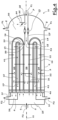
- Fig.1 schematically shows the longitudinal view of the heat exchanger (1a) according to a preferred configuration of the present invention.
- the heat exchanger (1a) shown in Fig.1 is of shell-and-tube type, has a substantially cylindrical geometry and comprises U-tubes (3) consisting of a first straight leg (12) and a second straight leg (13) hydraulically connected to each other at one end by U-bends (14) and connected to the other end at the first bores (4b) of a tube-sheet (4a).
- the first and second legs (12,13) of the exchanging tubes (3) form a first and second set of legs respectively (12,13).
- the heat exchanger (1a) also comprises a shell (2) enveloping the tube-bundle and connected to the tube-sheet (4a), a tube-side distributor (5) connected to the tube-sheet (4a) on the side opposite the tube-bundle, first and second tube-side connections (9,10) placed on the distributor (5) to enter and extract the tube-side fluid (F2), first and second shell-side connections (7,8) placed on the shell (2) to enter and extract the shell-side fluid (F1).
- the distributor (5) is divided in two distributing zones (25,26), not directly in fluid communication with each other, by means of at least one first wall (6); the first distributing zone (25) is in fluid communication with the first tube-side connection (9) and with the first set of legs (12), the second distributing zone (26) is in fluid communication with the second tube-side connections (10) and with the second set of legs (13).
- the heat exchanger (1a) of Fig.1 has a substantially axial-symmetric tube-bundle and a concentric tube-layout of the exchanging tubes (3).
- the first set of legs (12) forms a first ring-shaped tube-layout, inside which there is a circular area not crossed by the exchanging tubes (3); the second set of legs (13) forms a second ring-shaped tube-layout surrounding the first tube-layout.
- the first and second sets of legs (12,13) are respectively provided with first and second cross-baffles (21,22).
- the legs (12,13) cross the cross-baffles (21,22).
- the heat exchanger (1a) of Fig.1 also comprises a first longitudinal baffle (15), a first transversal baffle (16) and a second wall (27).
- the first longitudinal baffle (15), of substantially cylindrical geometry and not crossed by the exchanging tubes (3), is concentrically installed relative to the shell (2) and placed between the two sets of legs (12,13), i.e. between the first and second tube-layout of the exchanging tubes (3), and longitudinally extends for almost the entire length of the legs (12,13).
- the first longitudinal baffle (15) has a first end (17) facing the tube-sheet (4a) and a second end (18) facing the U-bends (14) and adjacent to the U-bends.
- the first end (17) is free, and preferably open, so as to form a first passage or opening (42) for the shell-side fluid (F1) between the first longitudinal baffle (15) and the tube-sheet (4a).
- the first end (17) of the first longitudinal baffle (15) is preferably adjacent to the tube-sheet (4a).
- the first transversal baffle (16) is orthogonal to the longitudinal axis (11) and adjacent to the U-bends (14), and basically is a ring-shaped portion of disc. Essentially, the first transversal baffle (16) has a shape corresponding to the second tube-layout of the second set of legs (13).
- the first transversal baffle (16) therefore, has an inner end (33) and an outer end (20), corresponding respectively to the diameter of the inner circle and the diameter of the outer circle of the ring.
- the inner end (33) forms a second passage or opening (43) through which the shell-side fluid (F1) flows.
- the outer end (20) is radially spaced from the shell (2) to form an annular passage or opening for the shell-side fluid (F1).
- the first transversal baffle (16) is provided with second bores (19) so to be crossed by the second set of legs (13).
- the first longitudinal baffle (15) is attached to the first transversal baffle (16) in a substantially fluid-tight manner.
- the first longitudinal baffle (15) is attached to the first transversal baffle (16) near the second end (18); preferably, the second end (18) is attached near the inner end (33) of the first transversal baffle (16).
- the first transversal baffle (16), at the second bores (19), forms a substantially fluid-tight fastening with the second legs (13).
- the first transversal baffle (16) forms a terminal fastening (28) substantially fluid-tight with the shell (2) or the first shell-side connection (7) via the second wall (27).
- the first transversal baffle (16) is attached to the second wall (27) in a substantially fluid-tight manner and the second wall (27) forms the terminal fastening (28) with the shell (2) or with the first shell-side connection (7).
- the first transversal baffle (16) is attached to the second wall (27) near the outer end (20).
- the second wall (27) is not crossed by the exchanging tubes (3). Consequently, the first longitudinal baffle (15), the first transversal baffle (16) and the second wall (27) form a dividing system (41) substantially fluid-tight with respect to the shell-side fluid (F1).
- the dividing system (41) and the cross-baffles (21,22) are substantially axial-symmetrical with respect to the longitudinal axis (11).
- the second legs (13) are juxtaposed to or hydraulically rolled against the second bores (19) of the first transversal baffle (16).
- the second wall (27) is provided with at least one expansion element or joint (29) substantially fluid-tight that allows the tube-bundle to lengthen and the first baffles (15,16) to move, due to thermal expansion, without excessive mechanical stress.
- This expansion element or joint (29) may be a bellows or a low-friction sliding joint; in the case of a sliding joint, the hydraulic sealing is preferably obtained with a gasket interposed to the two sliding parts.
- the terminal fastening (28) corresponds to an expansion element or joint (29); preferably, the expansion joint (29) is a sliding joint formed by the second wall (27) and the shell (2) side by side each other.
- the dividing system (41) longitudinally divides the tube-bundle in two zones useful for heat exchange; therefore, the exchanging zones are longitudinally adjacent and are not surrounded by the dividing system (41).
- the first exchanging zone ( 23 ), corresponding to a first pass of the shell-side fluid (F1), comprises the first set of legs (12), while the second exchanging zone ( 24 ), corresponding to a second pass of the shell-side fluid (F1), comprises the second set of legs (13).
- the first exchanging zone ( 23 ) is in fluid communication with the first shell-side connection (7) and the second exchanging zone ( 24 ) is in fluid communication with the second shell side connections (8); the two exchanging zones ( 23 , 24 ) are in fluid communication with each other by means of the first passage or opening (42) at the first end (17) of the first longitudinal baffle (15).
- the U-bends (14) are part of the first exchanging zone ( 23 ).
- the tube-side fluid (F2) is introduced into the first distributing zone (25) through the first tube-side connection (9) and then distributed inside the tubes of the first set of legs (12), where it flows towards the U-bends.
- the shell-side fluid (F1) is introduced into the shell (2) through the first shell-side connection (7) in opposite position with respect to the tube-sheet (4a), is channeled by the second wall (27) and then enters the first exchanging zone ( 23 ) through a second passage or opening (43) delimited by the inner end (33) of the first transversal baffle (16).
- the shell-side fluid (F1) in the first exchanging zone ( 23 ) flows towards the tube-sheet (4a) in counter-current with the tube-side fluid (F2), crosses the first set of legs (12), indirectly exchanges heat with the tube-side fluid (F2), arrives at the first end (17) of the first longitudinal baffle (15) and then, through the first passage or opening (42), enters the second exchanging zone ( 24 ) by reversing the sense of the flow.
- the shell-side fluid (F1) in the second exchanging zone ( 24 ) flows towards the U-bends (14) in counter-current with the tube-side fluid (F2), crosses the second set of legs (13), indirectly exchanges heat with the tube-side fluid (F2), arrives at the annular opening delimited by the outer end (20) of the first transversal baffle (16) and then flows towards the second shell-side connections (8) to exit the shell (2).
- Fig.2 shows a cross-sectional view (X-X') of the heat exchanger (1a) shown in Fig.1 and, more specifically, shows the tube-layout of the exchanging tubes (3).
- the tube-layout is essentially axial-symmetric and concentric. Starting from the center of the shell (2) and proceeding in a radial direction, there is a central circular area (37) not crossed by the exchanging tubes (3), an innermost ring corresponding to the first tube-layout (38) of the first set of legs (12) surrounding the central circular area (37), and an outermost ring corresponding to the second tube-layout (39) of the second set of legs (13) surrounding the first tube-layout (38).
- the U-bends (14) connect the legs (12,13) relative to the two tubelayouts (38,39).
- the first longitudinal baffle (15) is concentrically interposed to the two tubelayouts (38,39); the first tube-layout (38) and the central circular area (37) relate to the first exchanging zone ( 23 ), while the second tube-layout (39) relates to the second exchanging zone ( 24 ).
- the central circular area (37) not crossed by the exchanging tubes (3) has a diameter between 100mm and 1000mm.
- Fig.3 schematically shows the longitudinal view of the heat exchanger (1b) according to a preferred configuration of the present invention.
- the heat exchanger (1b) of Fig.3 is structurally equivalent to that of Fig.1 except for the presence of a second longitudinal baffle; in other words, the elements and construction details, and the relative numbering, of the heat exchanger (1b) shown in Fig.3 are equivalent to those of the heat exchanger (1a) shown in Fig. 1 , except for the second longitudinal baffle. So, for simplicity, the description of the heat exchanger (1b) of Fig.3 is partially omitted.
- the heat exchanger (1b) of Fig.3 is characterized by the presence in the shell (2) of a second longitudinal baffle (30), substantially cylindrical in shape, installed concentrically with respect to the shell (2) and interposed to the second set of legs (13) and the shell (2).
- the second longitudinal baffle (30) has a third end (31) substantially fluid-tight connected to the tube-sheet (4a) and a fourth end (32) facing the U-bends (14) which is free and, preferably, open.
- the fourth end (32) is near the U-bends (14) or placed after the U-bends (14).
- the second longitudinal baffle (30) forms a conveying zone ( 40 ) with the shell (2) not crossed by the exchanging tubes (3) and in fluid communication with the second exchanging zone ( 24 ) near the fourth end (32).
- the second shell-side connections (8) are positioned near the tube-sheet (4a).
- the shell-side fluid (F1) after having crossed the second exchanging zone ( 24 ), where it flows from the tube-sheet (4a) towards the U-bends (14) in counter-current with the tube-side fluid (F2), at the fourth end (32) enters the conveying zone ( 40 ) and reverses the sense of its flow, flowing towards the tube-sheet (4a) to exit the shell (2) through the second shell-side connections (8).
- the conveying zone ( 40 ) has the function of thermally shielding the shell (2) if the shell-side fluid (F1) still has a too high temperature at the entrance to the second exchanging zone ( 24 ).
- Fig.4 schematically shows the longitudinal view of the heat exchanger (1c) according to a preferred configuration of the present invention.
- the heat exchanger (1c) of Fig.4 is structurally equivalent to that of Fig.1 except for the position of the first transversal baffle and the position of the second wall; in other words, the elements and construction details, and the relative numbering, of the heat exchanger (1c) shown in Fig.4 are equivalent to those of the heat exchanger (1a) shown in Fig.1 , except for the first transversal baffle and for the second wall. So, for simplicity, the description of the heat exchanger (1c) of Fig.4 is partially omitted.
- the heat exchanger (1c) of Fig.4 is characterized by the fact that the first transversal baffle (16) is crossed by the first set of legs (12).
- the first transversal baffle (16) is orthogonal to the longitudinal axis (11) and adjacent to the U-bends (14), and basically corresponds to a ring-shaped portion of disc.
- the first transversal baffle (16) has a shape corresponding to the first tube-layout (38) of the first set of legs (12).
- the first transversal baffle (16) therefore, has an inner end (33) and an outer end (20), corresponding respectively to the diameter of the inner circle and the diameter of the outer circle of the ring.
- the inner end (33) forms a second passage or opening (43) through which the shell-side fluid (F1) flows.
- the first transversal baffle (16) is provided with second bores (19) so to be crossed by the first set of legs (12).
- the first longitudinal baffle (15) is attached to the first transversal baffle (16) in a substantially fluid-tight manner.
- the first longitudinal baffle (15) is attached to the first transversal baffle (16) near the second extremity (18); preferably, the second end (18) is attached near the outer end (20) of the first transversal baffle (16).
- the first transversal baffle (16), near the second bores (19), forms a substantially fluid-tight fastening with the first legs (12).
- the first transversal baffle (16) forms a terminal fastening (28) substantially fluid-tight with the shell (2) or with the first shell-side connection (7) through the second wall (27).
- the first transversal baffle (16) is attached to the second wall (27) in a substantially fluid-tight manner and the second wall (27) forms the terminal fastening (28) with the shell (2) or with the first shell-side connection (7).
- the first transversal baffle (16) is attached to the second wall (27) near the inner end (33). Consequently, the first longitudinal baffle (15), the first transversal baffle (16) and the second wall (27) form a dividing system (41) substantially fluid-tight with respect to the shell-side fluid (F1).
- the dividing system (41) and the cross-baffles (21,22) are substantially axial-symmetric with respect to the longitudinal axis (11).
- the first legs (12) are juxtaposed to or hydraulically rolled against the second bores (19) of the first transversal baffle (16).
- the dividing system (41) longitudinally divides the tube-bundle in two zones useful for heat exchange; therefore, the exchanging zones are longitudinally adjacent and are not surrounded by the dividing system (41).
- the first exchanging zone ( 23 ), corresponding to a first pass of the shell-side fluid (F1), comprises the first set of legs (12), while the second exchanging zone ( 24 ), corresponding to a second pass of the shell-side fluid (F1), comprises the second set of legs (13).
- the first exchanging zone ( 23 ) is in fluid communication with the first shell-side connection (7) and the second exchanging zone ( 24 ) is in fluid communication with the second shell side connections (8); the two exchanging zones ( 23 , 24 ) are in fluid communication with each other by means of the first passage or opening (42) at the first end (17) of the first longitudinal baffle (15).
- the U-bends (14) are part of the second exchanging zone ( 24 ).
- the heat exchanger (1c) of Fig.4 also comprises a bypass duct or opening (34), mounted on the second wall (27), which directly connects the shell-side fluid (F1) flowing in the first shell-side connection (7) with the shell-side fluid (F1) flowing in the second shell-side connections (8).
- the first and second exchanging zones ( 23 , 24 ) are in fluid communication with each other also through the bypass duct (34).
- the bypass duct (34) is installed in a shell-side mixing area (36) corresponding to the shell area (2) after the U-bends (14) and opposite the tube-sheet (4a); in other words, the bypass duct (34) is installed in an area of the shell (2) relatively distant from the exchanging tubes (3).
- the bypass duct (34) is equipped with a regulating element (35), such as a valve or plunger, which opens or closes the bypass duct (34).
- the shell-side fluid (F1) enters the shell (2) through the first shell-side connection (7) and is conveyed by the second wall (27) to the first exchanging zone (23).
- the regulating element (35) opens the bypass duct (34)
- a fraction of the shell-side fluid (F1) coming from the first shell-side connection (7) is conveyed into the bypass duct (34) substantially bypassing the tube-bundle and thus substantially avoiding participating in the heat exchange with the tube-side fluid (F2).
- the bypassed fraction of the shell-side fluid (F1) which is at temperature T1, mixes with the fraction of the shell-side fluid (F1) leaving the second exchanging zone ( 24 ), which is at temperature T2; mixing takes place mainly in the shell mixing area (36).
- the shell-side fluid (F1) exiting the shell (2), through the second shell-side connections (8), is therefore at a temperature T3, intermediate between temperatures T1 and T2. It follows that the heat exchanger (1c) of Fig.4 , by opening and closing the regulating element (35), i.e. by increasing and decreasing the fraction of the bypassed shell-side fluid (F1), is able to operate with a control of the heat exchange performance.
- Fig.5 schematically shows the longitudinal view of the heat exchanger (1d) according to a preferred configuration of the present invention.
- the heat exchanger (1d) of Fig.5 is structurally equivalent to that of Fig.1 except for the absence of the second wall; in other words, the elements and construction details, and the relative numbering, of the heat exchanger (1d) shown in Fig.5 are equivalent to those of the heat exchanger (1a) shown in Fig.1 , except for the second wall. So, for simplicity, the description of the heat exchanger (1d) of Fig.5 is partially omitted.
- the heat exchanger (1d) of Fig.5 is characterized by the fact that the terminal fastening (28) is formed directly by the first transversal baffle (16) and the shell (2) and corresponds to an expansion element or joint (29); preferably, the expansion element or joint (29) is a low-friction sliding joint between the first transversal baffle (16) and the shell (2), suitably placed side by side each other.
- the substantially fluid-tight sliding joint (29) is preferably obtained by contact between the first transversal baffle (16) and the shell (2) or, preferably, by means of a gasket interposed between the first transversal baffle (16) and the shell (2) or by any other sealing device installed at the outer end (20) of the first transversal baffle (16).
- the expansion element or joint (29) therefore corresponds to the substantially fluid-tight terminal fastening (28) between the first transversal baffle (16) and the shell (2). Consequently, the first longitudinal baffle (15) and the first transversal baffle (16) form a dividing system (41) substantially fluid-tight with respect to the shell-side fluid (F1).
- the second shell-side connections (8) are positioned between the tube-sheet (4a) and the first transversal baffle (16).
- the dividing system (41) longitudinally divides the tube-bundle in two zones useful for heat exchange; therefore, the exchanging zones are longitudinally adjacent and are not surrounded by the dividing system (41).
- the first exchanging zone ( 23 ), corresponding to a first pass of shell-side fluid (F1), comprises the first set of legs (12), while the second exchanging zone ( 24 ), corresponding to a second pass of shell-side fluid (F1), comprises the second set of legs (13).
- the first exchanging zone ( 23 ) is in fluid communication with the first shell-side connection (7) and the second exchanging zone ( 24 ) is in fluid communication with the second shell-side connections (8); the two exchanging zones ( 23 , 24 ) are in fluid communication with each other by means of the first passage or opening (42) at the first end (17) of the first longitudinal baffle (15).
- the U-bends (14) are part of the first exchanging zone ( 23 ).
- the heat exchanger of Fig.5 also comprises a second transversal baffle (44) installed in the shell (2) adjacent to the tube-sheet (4a) and, specifically, positioned between the tube-sheet (4a) and the first end (17) of the first longitudinal baffle (15) so that the shell-side fluid (F1) can flow between the first longitudinal baffle (15) and the second transversal baffle (44).
- the first passage or opening (42) is formed between the first longitudinal baffle (15) and the second transversal baffle (44).
- the second transversal baffle (44) essentially a disc crossed by the first and second sets of legs (12,13), is orthogonal to the longitudinal axis (11), has a diameter comparable to or greater than the external diameter of the second tube-layout (39) and has the function of forming a stagnation zone (45) between the tube-sheet (4a) and the second transversal baffle (44), where the shell-side fluid (F1) is essentially stagnant.
- this stagnation zone (45) is filled or provided with thermally insulating material and/or with material with low radiative emissivity.
- the second transversal baffle (44) is spaced from the tube-sheet by about 50-100mm. The stagnation zone (45) allows to thermally shield the tube-sheet (4a) if the shell-side fluid (F1) at the tube-sheet (4a) still has a too high temperature.
- the shell-side fluid (F1) is introduced into the shell (2) through the first shell-side connection (7) in the opposite position with respect to the tube-sheet (4a), and enters the first exchanging zone ( 23 ) through the second passage or opening (43) delimited by the inner end (33) of the first transversal baffle (16).
- the shell-side fluid (F1) in the first exchanging zone ( 23 ) flows towards the tube-sheet (4a) in counter-current with the tube-side fluid (F2), crosses the first set of legs (12), indirectly exchanges heat with the tube-side fluid (F2), arrives at the first end (17) of the first longitudinal baffle (15) and then enters, through the first passage or opening (42), in the second exchanging zone ( 24 ) reversing the sense of the flow.
- the shell-side fluid (F1) in the second exchanging zone ( 24 ) flows towards the U-bends (14) in counter-current with the tube-side fluid (F2), crosses the second set of legs (13), indirectly exchanges heat with the tube-side fluid (F2) and then exits from the shell (2) through the second shell-side connections (8).
- the heat exchanger (1a,1b,1c,1d) object of the present invention has the first transversal baffle (16) crossed by all the straight legs of the exchanging tubes (3).
- the first transversal baffle (16) is basically a portion of a disc with a ring shape with an inner end (33) forming the second passage or opening (43) for the shell-side fluid (F1) and with an outer end (20), and is provided with second (19) and third bores so as to be crossed by both the first and second legs (12,13).
- the first transversal baffle (16) is substantially fluid-tight, at the second bores (19), relative to a single set of legs.
- the first transversal baffle (16) is substantially fluid-tight relative to only one set of legs.
- Such sealing between the second bores (19) of the first transversal baffle (16) and the legs of one of the two sets can be obtained, for example, by juxtaposing or hydraulic rolling the legs to the bores or by drilling bores with a diameter such as to leave a leakage of shell-side fluid that is negligible.
- the heat exchanger (1a, 1b, 1c, 1d) object of the present invention comprises on shell-side a screen for the U-bends (14) so that the curves are marginally crossed by the shell-side fluid (F1) and therefore are not subjected to vibrations.
- the U-curves (14) are negligible for heat exchange.
- the longitudinal baffles (15,30) can be formed by two sheets placed side by side and forming a small gap in between; in other words, a longitudinal baffle (15,30) covered by the present invention can have a sandwich configuration.
- the gap has a radial size of about 4 ⁇ 12mm.
- the gap is in fluid communication with the shell (2) through openings such that the circulation of shell-side fluid (F1) in the gap is marginal during the operation of the heat exchanger (1a, 1b, 1c, 1d); in other words, the shell-side fluid (F1) in the gap is essentially stagnant.
- the gap is useful in order to limit or avoid the heat exchange on shell-side between adjacent areas of the tube-bundle, and therefore it is useful in order to increase the overall heat exchange efficiency.
- the first shell-side connection (7) is positioned on the cylindrical portion of the shell (2); preferably, the first shell-side connection (7) is positioned after the U-bends (14) on the cylindrical portion of the shell (2) and opposite the tube-sheet (4a).
- the heat exchanger (1a, 1b, 1c) shown in Fig.1 , Fig.3 and Fig.4 has a non-axial-symmetric second wall (27).
- the heat exchanger (1a, 1b, 1c, 1d) object of the present invention is configured so that:
- the sense of the shell-side fluid (F1) related to the first and second shell-side connections (7,8) and the sense of the tube-side fluid (F2) related to the first and second tube-side connections (9,10), as shown in Fig.1 , Fig.2 , Fig.3 , Fig.4 and Fig.5 can be reversed without departing from the inventive concept of the present invention.
- the shell-side fluid (F1) enters from the second shell-side connections (8) and exits from the first shell-side connection (7)
- the tube-side fluid (F2) enters from the second tube-side connections (10) and exits from the first tube-side connection (9).
- the fluids (F1,F2) contact each other in pure counter-current, the shell-side fluid (F2) performs two passes and inverts the sense of the flow, after passing through a heat exchanging zone, adjacently to the tube-sheet (4a).
- the operating method of the heat exchanger (1a, 1b, 1c, 1d) covered by the present invention comprises following operations that are not necessarily sequential:
- the present invention achieves the scope to provide a heat exchanger (1a, 1b, 1c, 1d) where an indirect heat exchange is carried out between two fluids flowing in inverted counter-current configuration and therefore wherein the two counter-current fluids do not contact either at their highest temperatures or at their lowest temperatures.
- the heat exchanger (1a, 1b, 1c, 1d) disclosed here is able to operate with metal temperatures of the exchanging tubes (3) and tube-sheet (4a) that are more moderate compared to conventional heat exchangers, and therefore is able to mitigate or eliminate risks of localized overheating and corrosion, to allow the use of lower thicknesses and/or less expensive metallurgy, or to mitigate or eliminate risks of condensing/freezing or fluids flowing with excessive viscosity when operating at low temperatures or close to the pour point.
- the heat exchanger (1a,1b,1c,1d) disclosed here is also able to operate by performing a control of the heat exchange performance by means of the bypass device (34,35) inside the shell.
- heat exchanger object of the present invention is subjected in any case to numerous modifications and variants, all attributable to the same inventive concept.
- all details can be replaced with technically equivalent elements.
- construction materials, shapes and sizes can be of any type according to technical requirements.
Landscapes
- Engineering & Computer Science (AREA)
- Physics & Mathematics (AREA)
- Thermal Sciences (AREA)
- Mechanical Engineering (AREA)
- General Engineering & Computer Science (AREA)
- Heat-Exchange Devices With Radiators And Conduit Assemblies (AREA)
Abstract
Description
- The present invention refers to a shell-and-tube heat exchanger, with U-tubes, where the two sets of straight legs of the exchanging tubes distinctly belong to two shell-side zones. The two zones are separated by a longitudinally extended dividing system, substantially fluid-tight with respect to the shell-side fluid, and are each other in fluid communication adjacent to the tube-sheet. This configuration allows to indirectly contact the tube-side fluid and the shell-side fluid, for a heat exchange, according to an unconventional or inverted counter-current configuration.
- The heat exchange between two fluids at high temperature and pressure and characterized by a temperatures cross or proximate inlet and outlet temperatures is often performed by means of a shell-and-tube heat exchanger where the exchanging tubes are "U" shaped and the fluids are in counter-current. The U-tubes are efficient in eliminating stresses due to thermal expansion, significant at high temperatures; the configuration with counter-current fluids allows to increase the overall heat exchange efficiency and, when present, to control the temperatures cross.
- For example, the synthesis gas at high temperature and pressure for the production of hydrogen or ammonia from hydrocarbons is often cooled with steam or boiler feed-water whose outlet temperatures sometimes cross with, or are proximate to, the synthesis gas outlet temperatures. Such heat exchangers installed in process plants are usually called gas-gas exchangers, or steam superheaters, or feed-water preheaters.
- In shell-and-tube heat exchangers with U-tubes, the path of counter-current fluids is obtained by means of baffles installed in the shell, which divide the shell in two or more zones, crossed or not crossed by the tube-bundle. The baffles divert and convey the shell-side fluid so that it moves in the opposite sense from the tube-side fluid. In practice, the baffles make the shell-side fluid to flow in longitudinal direction first along one sense, contacting the first leg of the U-tubes, and then along the opposite sense, contacting the second leg of the U-tubes.
- Referring to a shell-and-tube heat exchanger with U-tubes and fluids in conventional counter-current configuration, one of the ends of the exchanging tubes adjacent to the tube-sheet is in contact with the tube-side fluid at the inlet temperature and with the shell-side fluid at the outlet temperature, while the other end of the exchanging tubes adjacent to the tube-sheet is in contact with the tube-side fluid at the outlet temperature and with the shell-side fluid at the inlet temperature. According to this conventional counter-current configuration, the two fluids reverse the sense of their flows and have intermediate temperatures at the U-bends.
- This conventional counter-current configuration presents a high heat exchange efficiency, or a high average temperature difference between the two fluids, and often allows to neutralize the temperature cross. However, one of the ends of the exchanging tubes adjacent to the tube-sheet is exposed to both the highest tube-side temperature and the highest shell-side temperature. As a result, a terminal portion of the tube-bundle, and possibly also a portion of the tube-sheet and cross-baffles, may work at high metal temperatures. This can force, if the fluids are at high temperature, to adopt high thicknesses and/or more valuable materials; in any case, this may entail the risk of overheating and/or corrosion. Similarly, the other end of the exchanging tubes adjacent to the tube-sheet is exposed to both the lowest tube-side temperature and the lowest shell-side temperature. As a result, a terminal portion of the tube-bundle, and possibly also a portion of the tube-sheet and cross-baffles, may work at low metal temperatures. This may entail, if the fluids are at low temperatures or close to the pour point, risks of freezing or excessive viscosity.
- On the contrary, referring to a shell-and-tube heat exchanger with U-tubes and with fluids according to an unconventional, or inverted, counter-current configuration as described by this invention, one end of the exchanging tubes adjacent to the tube-sheet is in contact with the tube-side fluid at inlet temperature and with the shell-side fluid at an intermediate temperature, while the other end of the exchanging tubes adjacent to the tube-sheet is in contact with the tube-side fluid at the outlet temperature and with the shell-side fluid at said intermediate temperature. According to this inverted counter-current configuration:
- the tube-side fluid and the shell-side fluid reverse the sense of their flows respectively at the U-bends and at the tube-sheet,
- the tube-side fluid has an intermediate temperature at the U-bends, and
- the shell-side fluid has an intermediate temperature at the tube-sheet.
- This inverted counter-current configuration presents a heat exchange efficiency, or an average temperature difference between the two fluids, and an efficiency for neutralizing the temperature cross that are lower than the conventional counter-current configuration. However, the inverted counter-current configuration described here has the advantage that the fluids do not cross each other either at their maximum or minimum temperatures and consequently the exchanging tubes and the tube-sheet work at more moderate metal temperatures than those generally experienced in a conventional counter-current configuration. This may allow the use of reduced thicknesses and/or less valuable metallurgy, limit/eliminate the risk of local overheating and corrosion, or limit/eliminate the risk of freezing, condensation or excessive viscosity.
- Scope of the present invention, therefore, is to provide a heat exchanger alternate to existing solutions, less problematic from a thermo-mechanical and metallurgical standpoint for high temperatures fluids, and less problematic from a fluid-dynamics standpoint for low temperatures fluids.
- In particular, the present invention provides a heat exchanger that can be useful for cooling a process fluid or heat carrier, such as a synthesis gas or a molten salt or a thermal oil or a slurry, at high temperature and circulating on shell-side, by means of steam or boiler water circulating in tubes, keeping operating temperatures and thermo-mechanical stresses of metal parts, such as exchanging tubes and tube-sheet, within moderate values. Alternatively, the present invention provides a heat exchanger that can be useful for processing a cryogenic fluid or a high-viscosity hydrocarbon while maintaining the metal temperatures of tubes and tube-sheet above the condensation or pour point.
- Optionally, the heat exchanger object of the present invention also allows the control of the heat exchange performance by means of internal bypass devices.
- The patent document No.
US3437077 , which represents the closest prior-art document to the present invention, describes a shell-and-tube heat exchanger, with U-tubes, designed to generate and superheat steam circulating on shell-side. The exchanging tubes are arranged with axial-symmetric configuration and concentric tube-layout. The shell comprises longitudinal and transversal baffles that surround a portion of the exchanging tubes and form a separate passage for the shell-side fluid. The heat exchanger described in the patent document No.US3437077 substantially differs from the heat exchanger object of the present invention because the patent document No.US3437077 describes: - a shell-side dividing system surrounding a portion of the tube-bundle,
- a set of straight legs of the U-tubes running through both the tube-bundle zones delimited by the dividing system, and
- two fluids contacted both in counter-current and, for a large portion of the tube-bundle, in co-current.
- As a result, the heat exchanger described in the patent document No.
US3437077 is not so efficient in attempering the metal temperatures of structural components and is inadequate to contact two fluids that have proximate or crossing inlet/outlet temperatures. - The available literature describes several technological solutions, of shell-and-tube type, apt to perform the heat exchange between two fluids characterized by high temperatures, high pressures and proximate or crossing inlet/outlet temperatures.
-
- Patent document No.
EP3169963 describes a shell-and-tube heat exchanger, with U-tubes and shell-side longitudinal baffles, where a baffle envelops the entire tube-bundle. -
- Patent document no.
EP1610081 describes a shell-and-tube heat exchanger with U-tubes. The shell contains two concentric tube-bundles and dividing baffles. - Patent document no.
EP3406999 describes a shell-and-tube heat exchanger, with U-tubes, where the shell contains a cylindrical longitudinal baffle connected to the tube-sheet such that a portion of the exchanging tubes does not contribute to the heat exchange. -
- The heat exchanger object of the present invention is of the shell-and-tube type, has substantially cylindrical geometry and U-tubes. The tube-layout of the exchanging tubes is axial-symmetric and concentric.
- The U-tubes consist of two straight legs where two ends are hydraulically connected to each other by a U-bend and the other two ends are connected to the bores of a tube-sheet. The straight legs form two sets of legs, related to the two tube-side and shell-side fluid passes.
- The heat exchanger object of the present invention comprises a shell-side dividing system, substantially fluid-tight with respect to the shell-side fluid, which longitudinally divides the tube-bundle in two exchanging zones in fluid communication with each other by means of a passage or opening formed by one end of the dividing system adjacent to the tube-sheet. The first and the second exchanging zone are longitudinally adjacent and comprise respectively the first set and the second set of legs of the exchanging tubes.
- The end of the dividing system forming the passage or opening between the two exchanging zones is free and preferably open. The dividing system related to the present invention, therefore, longitudinally divides the tube-bundle in two zones without surrounding them, contrary to what is taught by the aforementioned patent document No.
US3437077 . - The dividing system is configured to contact the fluids according to an inverted counter-current configuration. As described above, the inverted counter-current configuration requires that the fluids are contacted in pure counter-current, contrary to what is taught by the cited patent documents No.
US3437077 , No.EP1610081 and No.EP3406999 , and foresees that the shell-side fluid, after the first shell-side pass, reverses the sense of the longitudinal flow at the tube-sheet, instead of at the U-bends as contrarily taught by the cited patent documents No.US2774575 , No.US5915465 and No.EP3169963 . - The dividing system consists of a longitudinal baffle, a transversal baffle and preferably also of a wall, attached to each other in a substantially fluid-tight manner. The transversal baffle forms a substantially fluid-tight fastening with at least one of the two sets of legs of the exchanging tubes.
- Herein, reference is made to substantially fluid-tight fastenings or joints when the fastening or joint is configured to avoid the flow of the shell-side fluid or to make the flow of the shell-side fluid between the components attached to each other negligible.
- The substantially fluid-tight fastenings or joints can be obtained by welding, bolting, interlocking or simple juxtaposition, with or without interposed gaskets, installing a crossflow area so small to make the leakage between two structural parts negligible.
- The longitudinal baffle covered by this invention is essentially a cylindrical sheet; the transversal baffle covered by the present invention is essentially a ring-shaped disc or portion of disc.
- The detailed description of the heat exchanger object of this invention is accompanied by following figures:
-
Fig. 1 , where the longitudinal view of the heat exchanger is schematically shown according to a preferred configuration of the present invention; -
Fig.2 , where a cross-sectional view of the heat exchanger is schematically shown according to a preferred configuration of the present invention; -
Fig.3 , where the longitudinal view of the heat exchanger is schematically shown according to a preferred configuration of the present invention; -
Fig.4 , where the longitudinal view of the heat exchanger is schematically shown according to preferred configuration of the present invention; -
Fig.5 , where the longitudinal view of the heat exchanger is schematically shown according to a preferred configuration of the present invention. -
Fig.1 schematically shows the longitudinal view of the heat exchanger (1a) according to a preferred configuration of the present invention. - The heat exchanger (1a) shown in
Fig.1 is of shell-and-tube type, has a substantially cylindrical geometry and comprises U-tubes (3) consisting of a first straight leg (12) and a second straight leg (13) hydraulically connected to each other at one end by U-bends (14) and connected to the other end at the first bores (4b) of a tube-sheet (4a). The first and second legs (12,13) of the exchanging tubes (3) form a first and second set of legs respectively (12,13). The heat exchanger (1a) also comprises a shell (2) enveloping the tube-bundle and connected to the tube-sheet (4a), a tube-side distributor (5) connected to the tube-sheet (4a) on the side opposite the tube-bundle, first and second tube-side connections (9,10) placed on the distributor (5) to enter and extract the tube-side fluid (F2), first and second shell-side connections (7,8) placed on the shell (2) to enter and extract the shell-side fluid (F1). The distributor (5) is divided in two distributing zones (25,26), not directly in fluid communication with each other, by means of at least one first wall (6); the first distributing zone (25) is in fluid communication with the first tube-side connection (9) and with the first set of legs (12), the second distributing zone (26) is in fluid communication with the second tube-side connections (10) and with the second set of legs (13). - The heat exchanger (1a) of
Fig.1 has a substantially axial-symmetric tube-bundle and a concentric tube-layout of the exchanging tubes (3). The first set of legs (12) forms a first ring-shaped tube-layout, inside which there is a circular area not crossed by the exchanging tubes (3); the second set of legs (13) forms a second ring-shaped tube-layout surrounding the first tube-layout. The first and second sets of legs (12,13) are respectively provided with first and second cross-baffles (21,22). The cross-baffles (21,22), substantially portions of disc orthogonal to the longitudinal axis (11), support the exchanging tubes (3) and make tortuous the longitudinal flow of the shell-side fluid (F1). The legs (12,13) cross the cross-baffles (21,22). - The heat exchanger (1a) of
Fig.1 , on shell-side, also comprises a first longitudinal baffle (15), a first transversal baffle (16) and a second wall (27). The first longitudinal baffle (15), of substantially cylindrical geometry and not crossed by the exchanging tubes (3), is concentrically installed relative to the shell (2) and placed between the two sets of legs (12,13), i.e. between the first and second tube-layout of the exchanging tubes (3), and longitudinally extends for almost the entire length of the legs (12,13). The first longitudinal baffle (15) has a first end (17) facing the tube-sheet (4a) and a second end (18) facing the U-bends (14) and adjacent to the U-bends. The first end (17) is free, and preferably open, so as to form a first passage or opening (42) for the shell-side fluid (F1) between the first longitudinal baffle (15) and the tube-sheet (4a). The first end (17) of the first longitudinal baffle (15) is preferably adjacent to the tube-sheet (4a). The first transversal baffle (16) is orthogonal to the longitudinal axis (11) and adjacent to the U-bends (14), and basically is a ring-shaped portion of disc. Essentially, the first transversal baffle (16) has a shape corresponding to the second tube-layout of the second set of legs (13). The first transversal baffle (16), therefore, has an inner end (33) and an outer end (20), corresponding respectively to the diameter of the inner circle and the diameter of the outer circle of the ring. The inner end (33) forms a second passage or opening (43) through which the shell-side fluid (F1) flows. The outer end (20) is radially spaced from the shell (2) to form an annular passage or opening for the shell-side fluid (F1). The first transversal baffle (16) is provided with second bores (19) so to be crossed by the second set of legs (13). - The first longitudinal baffle (15) is attached to the first transversal baffle (16) in a substantially fluid-tight manner. Preferably, the first longitudinal baffle (15) is attached to the first transversal baffle (16) near the second end (18); preferably, the second end (18) is attached near the inner end (33) of the first transversal baffle (16). The first transversal baffle (16), at the second bores (19), forms a substantially fluid-tight fastening with the second legs (13). The first transversal baffle (16) forms a terminal fastening (28) substantially fluid-tight with the shell (2) or the first shell-side connection (7) via the second wall (27). More specifically, the first transversal baffle (16) is attached to the second wall (27) in a substantially fluid-tight manner and the second wall (27) forms the terminal fastening (28) with the shell (2) or with the first shell-side connection (7). Preferably, the first transversal baffle (16) is attached to the second wall (27) near the outer end (20). The second wall (27) is not crossed by the exchanging tubes (3). Consequently, the first longitudinal baffle (15), the first transversal baffle (16) and the second wall (27) form a dividing system (41) substantially fluid-tight with respect to the shell-side fluid (F1). The dividing system (41) and the cross-baffles (21,22) are substantially axial-symmetrical with respect to the longitudinal axis (11).
- Preferably, the second legs (13) are juxtaposed to or hydraulically rolled against the second bores (19) of the first transversal baffle (16).
- The second wall (27) is provided with at least one expansion element or joint (29) substantially fluid-tight that allows the tube-bundle to lengthen and the first baffles (15,16) to move, due to thermal expansion, without excessive mechanical stress. This expansion element or joint (29) may be a bellows or a low-friction sliding joint; in the case of a sliding joint, the hydraulic sealing is preferably obtained with a gasket interposed to the two sliding parts.
- According to an alternative preferred configuration, not shown in the figure, the terminal fastening (28) corresponds to an expansion element or joint (29); preferably, the expansion joint (29) is a sliding joint formed by the second wall (27) and the shell (2) side by side each other.
- According to
Fig.1 , the dividing system (41) longitudinally divides the tube-bundle in two zones useful for heat exchange; therefore, the exchanging zones are longitudinally adjacent and are not surrounded by the dividing system (41). The first exchanging zone (23), corresponding to a first pass of the shell-side fluid (F1), comprises the first set of legs (12), while the second exchanging zone (24), corresponding to a second pass of the shell-side fluid (F1), comprises the second set of legs (13). The first exchanging zone (23) is in fluid communication with the first shell-side connection (7) and the second exchanging zone (24) is in fluid communication with the second shell side connections (8); the two exchanging zones (23,24) are in fluid communication with each other by means of the first passage or opening (42) at the first end (17) of the first longitudinal baffle (15). The U-bends (14) are part of the first exchanging zone (23). - According to
Fig. 1 , the tube-side fluid (F2) is introduced into the first distributing zone (25) through the first tube-side connection (9) and then distributed inside the tubes of the first set of legs (12), where it flows towards the U-bends. The tube-side fluid (F2) leaving the second set of legs (13), where it flows towards the tube-sheet (4a), is collected in the second distributing zone (26) to be extracted through the second tube-side connections (10). The shell-side fluid (F1) is introduced into the shell (2) through the first shell-side connection (7) in opposite position with respect to the tube-sheet (4a), is channeled by the second wall (27) and then enters the first exchanging zone (23) through a second passage or opening (43) delimited by the inner end (33) of the first transversal baffle (16). The shell-side fluid (F1) in the first exchanging zone (23) flows towards the tube-sheet (4a) in counter-current with the tube-side fluid (F2), crosses the first set of legs (12), indirectly exchanges heat with the tube-side fluid (F2), arrives at the first end (17) of the first longitudinal baffle (15) and then, through the first passage or opening (42), enters the second exchanging zone (24) by reversing the sense of the flow. The shell-side fluid (F1) in the second exchanging zone (24) flows towards the U-bends (14) in counter-current with the tube-side fluid (F2), crosses the second set of legs (13), indirectly exchanges heat with the tube-side fluid (F2), arrives at the annular opening delimited by the outer end (20) of the first transversal baffle (16) and then flows towards the second shell-side connections (8) to exit the shell (2). -
Fig.2 shows a cross-sectional view (X-X') of the heat exchanger (1a) shown inFig.1 and, more specifically, shows the tube-layout of the exchanging tubes (3). The tube-layout is essentially axial-symmetric and concentric. Starting from the center of the shell (2) and proceeding in a radial direction, there is a central circular area (37) not crossed by the exchanging tubes (3), an innermost ring corresponding to the first tube-layout (38) of the first set of legs (12) surrounding the central circular area (37), and an outermost ring corresponding to the second tube-layout (39) of the second set of legs (13) surrounding the first tube-layout (38). The U-bends (14) connect the legs (12,13) relative to the two tubelayouts (38,39). The first longitudinal baffle (15) is concentrically interposed to the two tubelayouts (38,39); the first tube-layout (38) and the central circular area (37) relate to the first exchanging zone (23), while the second tube-layout (39) relates to the second exchanging zone (24). Preferably, the central circular area (37) not crossed by the exchanging tubes (3) has a diameter between 100mm and 1000mm. -
Fig.3 schematically shows the longitudinal view of the heat exchanger (1b) according to a preferred configuration of the present invention. - The heat exchanger (1b) of
Fig.3 is structurally equivalent to that ofFig.1 except for the presence of a second longitudinal baffle; in other words, the elements and construction details, and the relative numbering, of the heat exchanger (1b) shown inFig.3 are equivalent to those of the heat exchanger (1a) shown inFig. 1 , except for the second longitudinal baffle. So, for simplicity, the description of the heat exchanger (1b) ofFig.3 is partially omitted. - The heat exchanger (1b) of
Fig.3 is characterized by the presence in the shell (2) of a second longitudinal baffle (30), substantially cylindrical in shape, installed concentrically with respect to the shell (2) and interposed to the second set of legs (13) and the shell (2). The second longitudinal baffle (30) has a third end (31) substantially fluid-tight connected to the tube-sheet (4a) and a fourth end (32) facing the U-bends (14) which is free and, preferably, open. Preferably, the fourth end (32) is near the U-bends (14) or placed after the U-bends (14). The second longitudinal baffle (30) forms a conveying zone (40) with the shell (2) not crossed by the exchanging tubes (3) and in fluid communication with the second exchanging zone (24) near the fourth end (32). The second shell-side connections (8) are positioned near the tube-sheet (4a). - According to
Fig.3 , the shell-side fluid (F1) after having crossed the second exchanging zone (24), where it flows from the tube-sheet (4a) towards the U-bends (14) in counter-current with the tube-side fluid (F2), at the fourth end (32) enters the conveying zone (40) and reverses the sense of its flow, flowing towards the tube-sheet (4a) to exit the shell (2) through the second shell-side connections (8). The conveying zone (40) has the function of thermally shielding the shell (2) if the shell-side fluid (F1) still has a too high temperature at the entrance to the second exchanging zone (24). -
Fig.4 schematically shows the longitudinal view of the heat exchanger (1c) according to a preferred configuration of the present invention. - The heat exchanger (1c) of
Fig.4 is structurally equivalent to that ofFig.1 except for the position of the first transversal baffle and the position of the second wall; in other words, the elements and construction details, and the relative numbering, of the heat exchanger (1c) shown inFig.4 are equivalent to those of the heat exchanger (1a) shown inFig.1 , except for the first transversal baffle and for the second wall. So, for simplicity, the description of the heat exchanger (1c) ofFig.4 is partially omitted. - The heat exchanger (1c) of
Fig.4 is characterized by the fact that the first transversal baffle (16) is crossed by the first set of legs (12). The first transversal baffle (16) is orthogonal to the longitudinal axis (11) and adjacent to the U-bends (14), and basically corresponds to a ring-shaped portion of disc. Essentially, the first transversal baffle (16) has a shape corresponding to the first tube-layout (38) of the first set of legs (12). The first transversal baffle (16), therefore, has an inner end (33) and an outer end (20), corresponding respectively to the diameter of the inner circle and the diameter of the outer circle of the ring. The inner end (33) forms a second passage or opening (43) through which the shell-side fluid (F1) flows. The first transversal baffle (16) is provided with second bores (19) so to be crossed by the first set of legs (12). - The first longitudinal baffle (15) is attached to the first transversal baffle (16) in a substantially fluid-tight manner. Preferably, the first longitudinal baffle (15) is attached to the first transversal baffle (16) near the second extremity (18); preferably, the second end (18) is attached near the outer end (20) of the first transversal baffle (16). The first transversal baffle (16), near the second bores (19), forms a substantially fluid-tight fastening with the first legs (12). The first transversal baffle (16) forms a terminal fastening (28) substantially fluid-tight with the shell (2) or with the first shell-side connection (7) through the second wall (27). More specifically, the first transversal baffle (16) is attached to the second wall (27) in a substantially fluid-tight manner and the second wall (27) forms the terminal fastening (28) with the shell (2) or with the first shell-side connection (7). Preferably, the first transversal baffle (16) is attached to the second wall (27) near the inner end (33). Consequently, the first longitudinal baffle (15), the first transversal baffle (16) and the second wall (27) form a dividing system (41) substantially fluid-tight with respect to the shell-side fluid (F1). The dividing system (41) and the cross-baffles (21,22) are substantially axial-symmetric with respect to the longitudinal axis (11).
- Preferably, the first legs (12) are juxtaposed to or hydraulically rolled against the second bores (19) of the first transversal baffle (16).
- According to
Fig.4 , the dividing system (41) longitudinally divides the tube-bundle in two zones useful for heat exchange; therefore, the exchanging zones are longitudinally adjacent and are not surrounded by the dividing system (41). The first exchanging zone (23), corresponding to a first pass of the shell-side fluid (F1), comprises the first set of legs (12), while the second exchanging zone (24), corresponding to a second pass of the shell-side fluid (F1), comprises the second set of legs (13). The first exchanging zone (23) is in fluid communication with the first shell-side connection (7) and the second exchanging zone (24) is in fluid communication with the second shell side connections (8); the two exchanging zones (23,24) are in fluid communication with each other by means of the first passage or opening (42) at the first end (17) of the first longitudinal baffle (15). The U-bends (14) are part of the second exchanging zone (24). - The heat exchanger (1c) of
Fig.4 also comprises a bypass duct or opening (34), mounted on the second wall (27), which directly connects the shell-side fluid (F1) flowing in the first shell-side connection (7) with the shell-side fluid (F1) flowing in the second shell-side connections (8). In other words, the first and second exchanging zones (23,24) are in fluid communication with each other also through the bypass duct (34). The bypass duct (34) is installed in a shell-side mixing area (36) corresponding to the shell area (2) after the U-bends (14) and opposite the tube-sheet (4a); in other words, the bypass duct (34) is installed in an area of the shell (2) relatively distant from the exchanging tubes (3). The bypass duct (34) is equipped with a regulating element (35), such as a valve or plunger, which opens or closes the bypass duct (34). - According to
Fig.4 , the shell-side fluid (F1) enters the shell (2) through the first shell-side connection (7) and is conveyed by the second wall (27) to the first exchanging zone (23). When the regulating element (35) opens the bypass duct (34), a fraction of the shell-side fluid (F1) coming from the first shell-side connection (7) is conveyed into the bypass duct (34) substantially bypassing the tube-bundle and thus substantially avoiding participating in the heat exchange with the tube-side fluid (F2). The bypassed fraction of the shell-side fluid (F1), which is at temperature T1, mixes with the fraction of the shell-side fluid (F1) leaving the second exchanging zone (24), which is at temperature T2; mixing takes place mainly in the shell mixing area (36). The shell-side fluid (F1) exiting the shell (2), through the second shell-side connections (8), is therefore at a temperature T3, intermediate between temperatures T1 and T2. It follows that the heat exchanger (1c) ofFig.4 , by opening and closing the regulating element (35), i.e. by increasing and decreasing the fraction of the bypassed shell-side fluid (F1), is able to operate with a control of the heat exchange performance. -
Fig.5 schematically shows the longitudinal view of the heat exchanger (1d) according to a preferred configuration of the present invention. - The heat exchanger (1d) of
Fig.5 is structurally equivalent to that ofFig.1 except for the absence of the second wall; in other words, the elements and construction details, and the relative numbering, of the heat exchanger (1d) shown inFig.5 are equivalent to those of the heat exchanger (1a) shown inFig.1 , except for the second wall. So, for simplicity, the description of the heat exchanger (1d) ofFig.5 is partially omitted. - The heat exchanger (1d) of
Fig.5 is characterized by the fact that the terminal fastening (28) is formed directly by the first transversal baffle (16) and the shell (2) and corresponds to an expansion element or joint (29); preferably, the expansion element or joint (29) is a low-friction sliding joint between the first transversal baffle (16) and the shell (2), suitably placed side by side each other. The substantially fluid-tight sliding joint (29) is preferably obtained by contact between the first transversal baffle (16) and the shell (2) or, preferably, by means of a gasket interposed between the first transversal baffle (16) and the shell (2) or by any other sealing device installed at the outer end (20) of the first transversal baffle (16). The expansion element or joint (29) therefore corresponds to the substantially fluid-tight terminal fastening (28) between the first transversal baffle (16) and the shell (2). Consequently, the first longitudinal baffle (15) and the first transversal baffle (16) form a dividing system (41) substantially fluid-tight with respect to the shell-side fluid (F1). The second shell-side connections (8) are positioned between the tube-sheet (4a) and the first transversal baffle (16). - According to
Fig.5 , the dividing system (41) longitudinally divides the tube-bundle in two zones useful for heat exchange; therefore, the exchanging zones are longitudinally adjacent and are not surrounded by the dividing system (41). The first exchanging zone (23), corresponding to a first pass of shell-side fluid (F1), comprises the first set of legs (12), while the second exchanging zone (24), corresponding to a second pass of shell-side fluid (F1), comprises the second set of legs (13). The first exchanging zone (23) is in fluid communication with the first shell-side connection (7) and the second exchanging zone (24) is in fluid communication with the second shell-side connections (8); the two exchanging zones (23,24) are in fluid communication with each other by means of the first passage or opening (42) at the first end (17) of the first longitudinal baffle (15). The U-bends (14) are part of the first exchanging zone (23). - The heat exchanger of
Fig.5 also comprises a second transversal baffle (44) installed in the shell (2) adjacent to the tube-sheet (4a) and, specifically, positioned between the tube-sheet (4a) and the first end (17) of the first longitudinal baffle (15) so that the shell-side fluid (F1) can flow between the first longitudinal baffle (15) and the second transversal baffle (44). In other words, the first passage or opening (42) is formed between the first longitudinal baffle (15) and the second transversal baffle (44). The second transversal baffle (44), essentially a disc crossed by the first and second sets of legs (12,13), is orthogonal to the longitudinal axis (11), has a diameter comparable to or greater than the external diameter of the second tube-layout (39) and has the function of forming a stagnation zone (45) between the tube-sheet (4a) and the second transversal baffle (44), where the shell-side fluid (F1) is essentially stagnant. According to a preferred configuration, this stagnation zone (45) is filled or provided with thermally insulating material and/or with material with low radiative emissivity. Preferably, the second transversal baffle (44) is spaced from the tube-sheet by about 50-100mm. The stagnation zone (45) allows to thermally shield the tube-sheet (4a) if the shell-side fluid (F1) at the tube-sheet (4a) still has a too high temperature. - According to
Fig.5 , the shell-side fluid (F1) is introduced into the shell (2) through the first shell-side connection (7) in the opposite position with respect to the tube-sheet (4a), and enters the first exchanging zone (23) through the second passage or opening (43) delimited by the inner end (33) of the first transversal baffle (16). The shell-side fluid (F1) in the first exchanging zone (23) flows towards the tube-sheet (4a) in counter-current with the tube-side fluid (F2), crosses the first set of legs (12), indirectly exchanges heat with the tube-side fluid (F2), arrives at the first end (17) of the first longitudinal baffle (15) and then enters, through the first passage or opening (42), in the second exchanging zone (24) reversing the sense of the flow. The shell-side fluid (F1) in the second exchanging zone (24) flows towards the U-bends (14) in counter-current with the tube-side fluid (F2), crosses the second set of legs (13), indirectly exchanges heat with the tube-side fluid (F2) and then exits from the shell (2) through the second shell-side connections (8). - According to an alternative preferred configuration not shown in
Fig. 1 ,Fig.3 ,Fig.4 andFig.5 , the heat exchanger (1a,1b,1c,1d) object of the present invention has the first transversal baffle (16) crossed by all the straight legs of the exchanging tubes (3). The first transversal baffle (16) is basically a portion of a disc with a ring shape with an inner end (33) forming the second passage or opening (43) for the shell-side fluid (F1) and with an outer end (20), and is provided with second (19) and third bores so as to be crossed by both the first and second legs (12,13). According to this alternative configuration, the first transversal baffle (16) is substantially fluid-tight, at the second bores (19), relative to a single set of legs. In other words, the first transversal baffle (16) is substantially fluid-tight relative to only one set of legs. Such sealing between the second bores (19) of the first transversal baffle (16) and the legs of one of the two sets can be obtained, for example, by juxtaposing or hydraulic rolling the legs to the bores or by drilling bores with a diameter such as to leave a leakage of shell-side fluid that is negligible. - According to a preferred configuration not shown in
Fig.1 ,Fig.3 ,Fig.4 andFig.5 , the heat exchanger (1a, 1b, 1c, 1d) object of the present invention comprises on shell-side a screen for the U-bends (14) so that the curves are marginally crossed by the shell-side fluid (F1) and therefore are not subjected to vibrations. In this case, the U-curves (14) are negligible for heat exchange. - According to a preferred configuration relating to the present invention, the longitudinal baffles (15,30) can be formed by two sheets placed side by side and forming a small gap in between; in other words, a longitudinal baffle (15,30) covered by the present invention can have a sandwich configuration. Preferably, the gap has a radial size of about 4÷12mm. The gap is in fluid communication with the shell (2) through openings such that the circulation of shell-side fluid (F1) in the gap is marginal during the operation of the heat exchanger (1a, 1b, 1c, 1d); in other words, the shell-side fluid (F1) in the gap is essentially stagnant. The gap is useful in order to limit or avoid the heat exchange on shell-side between adjacent areas of the tube-bundle, and therefore it is useful in order to increase the overall heat exchange efficiency.
- According to an alternative preferred configuration related to the present invention, the first shell-side connection (7) is positioned on the cylindrical portion of the shell (2); preferably, the first shell-side connection (7) is positioned after the U-bends (14) on the cylindrical portion of the shell (2) and opposite the tube-sheet (4a). In this case, the heat exchanger (1a, 1b, 1c) shown in
Fig.1 ,Fig.3 andFig.4 has a non-axial-symmetric second wall (27). - According to
Fig.1 ,Fig.3 ,Fig.4 andFig.5 , the heat exchanger (1a, 1b, 1c, 1d) object of the present invention is configured so that: - The shell-side fluid (F1) and the tube-side fluid (F2) indirectly exchange heat flowing in pure counter-current;
- The shell-side fluid (F1) executes two passes through the tube-bundle, corresponding to the two exchanging zones (23,24);
- The shell-side fluid (F1) reverses the sense of its flow, after executing a pass on shell-side, adjacent to the tube-sheet (4a) or in an area of the tube-bundle longitudinally opposite to the U-bends (14).
- As an expert in the field can understand, the sense of the shell-side fluid (F1) related to the first and second shell-side connections (7,8) and the sense of the tube-side fluid (F2) related to the first and second tube-side connections (9,10), as shown in
Fig.1 ,Fig.2 ,Fig.3 ,Fig.4 andFig.5 , can be reversed without departing from the inventive concept of the present invention. In other words, according to an alternative preferred configuration of the present invention, the shell-side fluid (F1) enters from the second shell-side connections (8) and exits from the first shell-side connection (7), and the tube-side fluid (F2) enters from the second tube-side connections (10) and exits from the first tube-side connection (9). The fluids (F1,F2) contact each other in pure counter-current, the shell-side fluid (F2) performs two passes and inverts the sense of the flow, after passing through a heat exchanging zone, adjacently to the tube-sheet (4a). - In accordance with the above description, the operating method of the heat exchanger (1a, 1b, 1c, 1d) covered by the present invention comprises following operations that are not necessarily sequential:
- The introduction of the tube-side fluid (F2) into one of the sets of legs (12,13) of the exchanging tubes (3) through first or second tube-side connections (9,10) and first or second distributing zones (25,26);
- The outflow of tube-side fluid (F2) first in one set and then in the other set of legs (12,13);
- The extraction of the tube-side fluid (F2) from the other set of legs (12,13) of the exchanging tubes (3) through first or second distributing zones (25,26) and first or second tube-side connections (9,10);
- The introduction of the shell-side fluid (F1) in an exchanging zone (23,24) by means of first or second shell-side connections (7,8);
- The outflow of the shell-side fluid (F1) first in an exchanging zone (23,24) in counter-current with the tube-side fluid (F2);
- The reversal of the sense of the longitudinal flow on shell-side (F1) near the tube-sheet (4a) or in an area longitudinally opposite to the U-bends (14);
- The flow of the shell-side fluid (F1) in the other exchanging zone (23,24) in counter-current with the tube-side fluid (F2);
- The extraction of the shell-side fluid (F1) through first or second shell-side connections (7,8).
- From the above, the present invention achieves the scope to provide a heat exchanger (1a, 1b, 1c, 1d) where an indirect heat exchange is carried out between two fluids flowing in inverted counter-current configuration and therefore wherein the two counter-current fluids do not contact either at their highest temperatures or at their lowest temperatures. The heat exchanger (1a, 1b, 1c, 1d) disclosed here, therefore, is able to operate with metal temperatures of the exchanging tubes (3) and tube-sheet (4a) that are more moderate compared to conventional heat exchangers, and therefore is able to mitigate or eliminate risks of localized overheating and corrosion, to allow the use of lower thicknesses and/or less expensive metallurgy, or to mitigate or eliminate risks of condensing/freezing or fluids flowing with excessive viscosity when operating at low temperatures or close to the pour point. In addition, the heat exchanger (1a,1b,1c,1d) disclosed here is also able to operate by performing a control of the heat exchange performance by means of the bypass device (34,35) inside the shell.
- The heat exchanger object of the present invention, as conceived and described, is subjected in any case to numerous modifications and variants, all attributable to the same inventive concept. In addition, all details can be replaced with technically equivalent elements. In practice, construction materials, shapes and sizes, can be of any type according to technical requirements.
- The scope of protection of this invention is defined by the attached claims.
Claims (13)
- Heat exchanger (1a,1b,1c,1d) of shell-and-tube type, with substantially cylindrical geometry and substantially axial-symmetric tube-bundle relative to the longitudinal axis (11), apt to an indirect heat exchange between a shell-side fluid (F1) and a tube-side fluid (F2), comprising:- A tube-sheet (4a) provided with first bores (4b),- A shell (2) enveloping the tube-bundle,- A distributor (5) connected to said tube-sheet (4a) on the opposite side relative to the tube bundle, internally provided with at least a first wall (6) forming at least a first and at least a second distributing zone (25,26) not in direct fluid communication each other,- Exchanging tubes (3) of "U" type having first and second straight legs (12,13) at one end hydraulically connected each other by means of U-bends (14) and at the other end connected to said first bores (4b), wherein said first and second legs (12,13) respectively form a first and a second tube-layout (38,39), wherein said second tube-layout (39) surrounds said first tube-layout (38), and wherein said first and second legs (12,13) are respectively in fluid communication with said first and second distributing zone (25,26),- At least a first and at least a second tube-side connection (9,10) installed on said distributor (5) for introducing and extracting said tube-side fluid (F2),- At least a first and at least a second shell-side connection (7,8) installed on said shell (2) for introducing and extracting said shell-side fluid (F1),- Shell-side first and second cross-baffles (21,22), respectively crossed by said first and second legs (12,13), apt to support said exchanging tubes (3) and to make tortuous the flow of said shell-side fluid (F1),- A shell-side dividing system (41), substantially fluid-tight relative to said shell-side fluid (F1), longitudinally extended for at least almost all the length of said legs (12,13) and longitudinally dividing said tube-bundle in a first and in a second heat exchanging zone (23,24) respectively comprising said first and second legs (12,13) and respectively in fluid communication with said first and second shell-side connections (7,8),said heat exchanger (1a, 1b, 1c, 1d) being characterized in that said dividing system (41) has a free and open end (17) facing said tube-sheet (4a) so to form a first passageway or opening (42) that puts in fluid communication said heat exchanging zones (23,24) and has an opposite end forming a terminal fastening (28) substantially fluid-tight with said shell (2) or said first shell-side connection (7).
- Heat exchanger (1a, 1b, 1c, 1d) according to claim 1, wherein said dividing system (41) comprises:- A first longitudinal baffle (15) with substantially cylindrical geometry longitudinally extended for almost all the length of said legs (12,13), concentrically installed relative to said shell (2) and in between said first and second legs (12,13), having a first end (17) corresponding to said free and open end facing said tube-sheet (4a) and a second end (18) adjacent to said U-bends (14),- A first transversal baffle (16) substantially corresponding to a ring-shaped portion of disc having an outer end (20) and an inner end (33) forming a second passageway or opening (43) for the shell-side fluid (F1), installed orthogonally relative to the longitudinal axis (11) and adjacently to said U-bends (14), provided with second bores (19) which said first and/or second legs (12,13) pass through,wherein said first longitudinal and transversal baffles (15,16) are connected each other in a substantially fluid-tight manner adjacently to said second end (18), wherein said first transversal baffle (16) forms with said first or second legs (12,13) adjacently to said second bores (19) a null or negligible passageway of the shell-side fluid (F1), and wherein said first transversal baffle (16), in a zone radially spaced from said second end (18), forms said terminal fastening (28).
- Heat exchanger (1a, 1b, 1c) according to claim 2, wherein said dividing system (41) comprises a second wall (27), not crossed by said exchanging tubes (3), connected in a substantially fluid-tight manner to said first transversal baffle (16) in a zone radially spaced from said second end (18), and wherein said terminal fastening (28) is formed by means of said second wall (27).
- Heat exchanger (1a,1b,1c,1d) according to claim 2 or 3, wherein said first transversal baffle (16) and said first or second legs (12,13) are connected each other by means of juxtaposition or hydraulic expansion of said first or second legs (12,13) against said second bores (19).
- Heat exchanger (1a, 1b, 1c, 1d) according to anyone of claims from 1 to 4, wherein said dividing system (41) comprises at least an expansion element or joint (29) substantially fluid-tight apt to allow the thermal expansions of said dividing system (41) and said exchanging tubes (3) reducing the mechanical stresses.
- Heat exchanger (1a,1b,1c,1d) according to claim 5, wherein said expansion element or joint (29) is installed on said second wall (27) and/or at said terminal fastening (28).
- Heat exchanger (1a, 1b, 1c) according to anyone of claims from 3 to 6, wherein said second wall (27) is provided with a bypass conduit or opening (34) provided with a regulating element (35) that opens or closes said bypass conduit or opening (34) so that a fraction of said shell-side fluid (F1) introduced in the shell (2) through said first or second shell-side connection (7,8) substantially bypasses said heat exchanging zones (23,24).
- Heat exchanger (1a,1b,1c,1d) according to anyone of claims from 1 to 7, comprising on shell-side a second longitudinal baffle (30) with substantially cylindrical geometry concentrically installed relative to said shell (2) and in between said second legs (13) and said shell (2) and having a third end (31) and a fourth end (32), wherein said second longitudinal baffle (30) forms with the shell (2) a conveying zone (40) not crossed by the exchanging tubes (3), and wherein said conveying zone (40) is in fluid communication with said second heat exchanging zone (24).
- Heat exchanger (1a, 1b, 1c, 1d) according to anyone of claims from 1 to 8, wherein said first and/or second longitudinal baffle (15,30) is formed by two concentric and juxtaposed sheets forming an annular gap in between in fluid communication with the shell (2) so that said shell-side fluid (F1) is substantially stagnant within said gap.
- Heat exchanger (1a,1b,1c,1d) according to anyone of claims from 1 to 9, comprising a second transversal baffle (44) substantially corresponding to a disc orthogonal to the longitudinal axis (11) and adjacent to said tube-sheet (4a), having a diameter equivalent to or greater than the outer diameter of said second tube-layout (39) and crossed by said exchanging tubes (3), wherein said second transversal baffle (44) and said tube-sheet (4a) delimit a stagnation zone (45), in fluid communication with the shell (2), where the shell-side fluid (F1) is substantially stagnant.
- Heat exchanger (1a, 1b, 1c, 1d) according to anyone of previous claims, wherein said fluids (F1,F2) flow along said legs (12,13) in pure counter-current configuration.
- Operating method of a heat exchanger (1a,1b,1c,1d) configured according to anyone of previous claims, comprising following operations not necessarily sequential:- The introduction of said tube-side fluid (F2) in said first or second legs (12,13) through said first or second tube-side connection (9,10) and said first or second distributing zone (25,26);- The outflow of said tube-side fluid (F2) within said legs (12,13);- The extraction of said tube-side fluid (F2) from said first or second legs (12,13) through said first or second distributing zone (25,26) and said first or second tube-side connection (9,10);- The introduction of said shell-side fluid (F1) in said first or second heat exchanging zone (23,24) through said first or second shell-side connection (7,8);- The outflow towards the tube-sheet (4a) of said shell-side fluid (F1) in one of said heat exchanging zones (23,24) in counter-current with said tube-side fluid (F2) and the subsequent indirect heat exchange between said fluids (F1,F2);- The inversion of the longitudinal flow sense of said shell-side fluid (F1) at said free and open first end (17) facing the tube-sheet (4a);- The outflow towards the U-bends (14) of said shell-side fluid (F1) in the next heat exchanging zone (23,24) in counter-current with said tube-side fluid (F2) and the subsequent indirect heat exchange between said fluids (F1,F2);- The extraction of said shell-side fluid (F1) through said first or second shell-side connection (7,8).
- Operating method of a heat exchanger (1a, 1b, 1c, 1d) according to claim 12, wherein said shell-side fluid (F1) introduced through said first or second shell-side connection (7,8) is bypassed towards said second or first shell-side connection (7,8) without substantially flowing through said heat exchanging zones (23,24).
Applications Claiming Priority (1)
| Application Number | Priority Date | Filing Date | Title |
|---|---|---|---|
| IT102022000026172A IT202200026172A1 (en) | 2022-12-21 | 2022-12-21 | HEAT EXCHANGER WITH FLUIDS IN INVERTED COUNTERFLOW CONFIGURATION AND RELATED OPERATING METHOD |
Publications (3)
| Publication Number | Publication Date |
|---|---|
| EP4390289A1 true EP4390289A1 (en) | 2024-06-26 |
| EP4390289C0 EP4390289C0 (en) | 2025-09-03 |
| EP4390289B1 EP4390289B1 (en) | 2025-09-03 |
Family
ID=85556740
Family Applications (1)
| Application Number | Title | Priority Date | Filing Date |
|---|---|---|---|
| EP23020452.1A Active EP4390289B1 (en) | 2022-12-21 | 2023-09-29 | Heat exchanger with fluids in inverted counter-current configuration and operating method thereof |
Country Status (2)
| Country | Link |
|---|---|
| EP (1) | EP4390289B1 (en) |
| IT (1) | IT202200026172A1 (en) |
Cited By (2)
| Publication number | Priority date | Publication date | Assignee | Title |
|---|---|---|---|---|
| CN119223068A (en) * | 2024-09-23 | 2024-12-31 | 中国船舶集团有限公司第七一九研究所 | Shell and tube heat exchanger head and shell and tube heat exchanger |
| EP4679023A1 (en) * | 2024-07-12 | 2026-01-14 | BITZER Kühlmaschinenbau GmbH | Tube bundle heat exchanger and refrigeration or heating system with a tube bundle heat exchanger |
Citations (4)
| Publication number | Priority date | Publication date | Assignee | Title |
|---|---|---|---|---|
| US3437077A (en) * | 1966-01-21 | 1969-04-08 | Babcock & Wilcox Co | Once-through vapor generator |
| US20050284606A1 (en) * | 2004-06-25 | 2005-12-29 | Haldor Topsoe A/S | Heat exchanger and heat exchange process |
| EP3286514B1 (en) * | 2015-04-24 | 2019-12-11 | Hexsol Italy S.r.l. | Heat exchanger |
| US11054196B2 (en) * | 2017-05-26 | 2021-07-06 | Alfa Laval Olmi S.P.A. | Shell-and-tube heat exchanger |
Family Cites Families (3)
| Publication number | Priority date | Publication date | Assignee | Title |
|---|---|---|---|---|
| US2774575A (en) | 1952-03-07 | 1956-12-18 | Worthington Corp | Regenerator |
| DK0864830T3 (en) | 1997-03-14 | 2002-02-04 | Borsig Gmbh | Heat exchanger with U-shaped pipes |
| EP2975353A1 (en) | 2014-07-16 | 2016-01-20 | Casale SA | Shell and tube heat exchangers |
-
2022
- 2022-12-21 IT IT102022000026172A patent/IT202200026172A1/en unknown
-
2023
- 2023-09-29 EP EP23020452.1A patent/EP4390289B1/en active Active
Patent Citations (4)
| Publication number | Priority date | Publication date | Assignee | Title |
|---|---|---|---|---|
| US3437077A (en) * | 1966-01-21 | 1969-04-08 | Babcock & Wilcox Co | Once-through vapor generator |
| US20050284606A1 (en) * | 2004-06-25 | 2005-12-29 | Haldor Topsoe A/S | Heat exchanger and heat exchange process |
| EP3286514B1 (en) * | 2015-04-24 | 2019-12-11 | Hexsol Italy S.r.l. | Heat exchanger |
| US11054196B2 (en) * | 2017-05-26 | 2021-07-06 | Alfa Laval Olmi S.P.A. | Shell-and-tube heat exchanger |
Cited By (2)
| Publication number | Priority date | Publication date | Assignee | Title |
|---|---|---|---|---|
| EP4679023A1 (en) * | 2024-07-12 | 2026-01-14 | BITZER Kühlmaschinenbau GmbH | Tube bundle heat exchanger and refrigeration or heating system with a tube bundle heat exchanger |
| CN119223068A (en) * | 2024-09-23 | 2024-12-31 | 中国船舶集团有限公司第七一九研究所 | Shell and tube heat exchanger head and shell and tube heat exchanger |
Also Published As
| Publication number | Publication date |
|---|---|
| IT202200026172A1 (en) | 2024-06-21 |
| EP4390289C0 (en) | 2025-09-03 |
| EP4390289B1 (en) | 2025-09-03 |
Similar Documents
| Publication | Publication Date | Title |
|---|---|---|
| EP4390289B1 (en) | Heat exchanger with fluids in inverted counter-current configuration and operating method thereof | |
| EP3169963B1 (en) | Shell and tube heat exchanger | |
| EP3631342B1 (en) | Shell-and-tube equipment with bypass | |
| US11054196B2 (en) | Shell-and-tube heat exchanger | |
| US11187471B2 (en) | Heat exchanger for severe service conditions | |
| US4907643A (en) | Combined heat exchanger system such as for ammonia synthesis reactor effluent | |
| KR20120088523A (en) | Heat exchanger | |
| US10684077B2 (en) | Tube-nest heat exchanger with improved structure | |
| CN110691953A (en) | Heat exchanger for a molten salt steam generator in a concentrated solar power plant | |
| US11454452B2 (en) | Heat exchanger for a molten salt steam generator in a concentrated solar power plant (III) | |
| EP3286514B1 (en) | Heat exchanger | |
| US20140090804A1 (en) | Heat Exchanger | |
| EP3502608B1 (en) | Heat exchanger for a molten salt steam generator in a concentrated solar power plant (iii) | |
| US11306972B2 (en) | Shell and tube heat exchangers | |
| EP4390295A1 (en) | Heat exchanger with longitudinal baffle and dual operating method thereof | |
| US20120312512A1 (en) | Heat exchanger | |
| US3610207A (en) | Vertical drum water tube waste heat recovery boiler | |
| RU2655891C1 (en) | Heat exchanging device (options) | |
| CN109959275B (en) | Heat exchanger and molten salt steam generator comprising at least one heat exchanger series |
Legal Events
| Date | Code | Title | Description |
|---|---|---|---|
| PUAI | Public reference made under article 153(3) epc to a published international application that has entered the european phase |
Free format text: ORIGINAL CODE: 0009012 |
|
| STAA | Information on the status of an ep patent application or granted ep patent |
Free format text: STATUS: THE APPLICATION HAS BEEN PUBLISHED |
|
| AK | Designated contracting states |
Kind code of ref document: A1 Designated state(s): AL AT BE BG CH CY CZ DE DK EE ES FI FR GB GR HR HU IE IS IT LI LT LU LV MC ME MK MT NL NO PL PT RO RS SE SI SK SM TR |
|
| STAA | Information on the status of an ep patent application or granted ep patent |
Free format text: STATUS: REQUEST FOR EXAMINATION WAS MADE |
|
| 17P | Request for examination filed |
Effective date: 20241216 |
|
| GRAP | Despatch of communication of intention to grant a patent |
Free format text: ORIGINAL CODE: EPIDOSNIGR1 |
|
| STAA | Information on the status of an ep patent application or granted ep patent |
Free format text: STATUS: GRANT OF PATENT IS INTENDED |
|
| INTG | Intention to grant announced |
Effective date: 20250523 |
|
| GRAS | Grant fee paid |
Free format text: ORIGINAL CODE: EPIDOSNIGR3 |
|
| GRAA | (expected) grant |
Free format text: ORIGINAL CODE: 0009210 |
|
| STAA | Information on the status of an ep patent application or granted ep patent |
Free format text: STATUS: THE PATENT HAS BEEN GRANTED |
|
| AK | Designated contracting states |
Kind code of ref document: B1 Designated state(s): AL AT BE BG CH CY CZ DE DK EE ES FI FR GB GR HR HU IE IS IT LI LT LU LV MC ME MK MT NL NO PL PT RO RS SE SI SK SM TR |
|
| REG | Reference to a national code |
Ref country code: CH Ref legal event code: EP |
|
| REG | Reference to a national code |
Ref country code: DE Ref legal event code: R096 Ref document number: 602023006186 Country of ref document: DE |
|
| REG | Reference to a national code |
Ref country code: IE Ref legal event code: FG4D |
|
| PGFP | Annual fee paid to national office [announced via postgrant information from national office to epo] |
Ref country code: AT Payment date: 20251020 Year of fee payment: 3 |
|
| U01 | Request for unitary effect filed |
Effective date: 20250916 |
|
| U07 | Unitary effect registered |
Designated state(s): AT BE BG DE DK EE FI FR IT LT LU LV MT NL PT RO SE SI Effective date: 20251007 |
|
| PG25 | Lapsed in a contracting state [announced via postgrant information from national office to epo] |
Ref country code: NO Free format text: LAPSE BECAUSE OF FAILURE TO SUBMIT A TRANSLATION OF THE DESCRIPTION OR TO PAY THE FEE WITHIN THE PRESCRIBED TIME-LIMIT Effective date: 20251203 |
|
| U1N | Appointed representative for the unitary patent procedure changed after the registration of the unitary effect |
Representative=s name: CONTESSINI, PIER CARLO; IT |
|
| U20 | Renewal fee for the european patent with unitary effect paid |
Year of fee payment: 3 Effective date: 20251205 |
|
| PG25 | Lapsed in a contracting state [announced via postgrant information from national office to epo] |
Ref country code: HR Free format text: LAPSE BECAUSE OF FAILURE TO SUBMIT A TRANSLATION OF THE DESCRIPTION OR TO PAY THE FEE WITHIN THE PRESCRIBED TIME-LIMIT Effective date: 20250903 |
|
| PG25 | Lapsed in a contracting state [announced via postgrant information from national office to epo] |
Ref country code: GR Free format text: LAPSE BECAUSE OF FAILURE TO SUBMIT A TRANSLATION OF THE DESCRIPTION OR TO PAY THE FEE WITHIN THE PRESCRIBED TIME-LIMIT Effective date: 20251204 |
|
| PG25 | Lapsed in a contracting state [announced via postgrant information from national office to epo] |
Ref country code: PL Free format text: LAPSE BECAUSE OF FAILURE TO SUBMIT A TRANSLATION OF THE DESCRIPTION OR TO PAY THE FEE WITHIN THE PRESCRIBED TIME-LIMIT Effective date: 20250903 |
|
| PG25 | Lapsed in a contracting state [announced via postgrant information from national office to epo] |
Ref country code: RS Free format text: LAPSE BECAUSE OF FAILURE TO SUBMIT A TRANSLATION OF THE DESCRIPTION OR TO PAY THE FEE WITHIN THE PRESCRIBED TIME-LIMIT Effective date: 20251203 |
|
| PG25 | Lapsed in a contracting state [announced via postgrant information from national office to epo] |
Ref country code: ES Free format text: LAPSE BECAUSE OF FAILURE TO SUBMIT A TRANSLATION OF THE DESCRIPTION OR TO PAY THE FEE WITHIN THE PRESCRIBED TIME-LIMIT Effective date: 20250903 |
|
| PG25 | Lapsed in a contracting state [announced via postgrant information from national office to epo] |
Ref country code: SM Free format text: LAPSE BECAUSE OF FAILURE TO SUBMIT A TRANSLATION OF THE DESCRIPTION OR TO PAY THE FEE WITHIN THE PRESCRIBED TIME-LIMIT Effective date: 20250903 |
|
| PG25 | Lapsed in a contracting state [announced via postgrant information from national office to epo] |
Ref country code: IS Free format text: LAPSE BECAUSE OF FAILURE TO SUBMIT A TRANSLATION OF THE DESCRIPTION OR TO PAY THE FEE WITHIN THE PRESCRIBED TIME-LIMIT Effective date: 20260103 |
|
| PG25 | Lapsed in a contracting state [announced via postgrant information from national office to epo] |
Ref country code: CZ Free format text: LAPSE BECAUSE OF FAILURE TO SUBMIT A TRANSLATION OF THE DESCRIPTION OR TO PAY THE FEE WITHIN THE PRESCRIBED TIME-LIMIT Effective date: 20250903 |
|
| PG25 | Lapsed in a contracting state [announced via postgrant information from national office to epo] |
Ref country code: SK Free format text: LAPSE BECAUSE OF FAILURE TO SUBMIT A TRANSLATION OF THE DESCRIPTION OR TO PAY THE FEE WITHIN THE PRESCRIBED TIME-LIMIT Effective date: 20250903 |