EP3406999A1 - Shell-and-tube heat exchanger - Google Patents
Shell-and-tube heat exchanger Download PDFInfo
- Publication number
- EP3406999A1 EP3406999A1 EP17425056.3A EP17425056A EP3406999A1 EP 3406999 A1 EP3406999 A1 EP 3406999A1 EP 17425056 A EP17425056 A EP 17425056A EP 3406999 A1 EP3406999 A1 EP 3406999A1
- Authority
- EP
- European Patent Office
- Prior art keywords
- tube
- shell
- heat exchanger
- fluid
- pressure chamber
- Prior art date
- Legal status (The legal status is an assumption and is not a legal conclusion. Google has not performed a legal analysis and makes no representation as to the accuracy of the status listed.)
- Granted
Links
Images





Classifications
-
- F—MECHANICAL ENGINEERING; LIGHTING; HEATING; WEAPONS; BLASTING
- F28—HEAT EXCHANGE IN GENERAL
- F28D—HEAT-EXCHANGE APPARATUS, NOT PROVIDED FOR IN ANOTHER SUBCLASS, IN WHICH THE HEAT-EXCHANGE MEDIA DO NOT COME INTO DIRECT CONTACT
- F28D7/00—Heat-exchange apparatus having stationary tubular conduit assemblies for both heat-exchange media, the media being in contact with different sides of a conduit wall
- F28D7/06—Heat-exchange apparatus having stationary tubular conduit assemblies for both heat-exchange media, the media being in contact with different sides of a conduit wall the conduits having a single U-bend
-
- F—MECHANICAL ENGINEERING; LIGHTING; HEATING; WEAPONS; BLASTING
- F28—HEAT EXCHANGE IN GENERAL
- F28F—DETAILS OF HEAT-EXCHANGE AND HEAT-TRANSFER APPARATUS, OF GENERAL APPLICATION
- F28F9/00—Casings; Header boxes; Auxiliary supports for elements; Auxiliary members within casings
- F28F9/02—Header boxes; End plates
- F28F9/0202—Header boxes having their inner space divided by partitions
-
- F—MECHANICAL ENGINEERING; LIGHTING; HEATING; WEAPONS; BLASTING
- F28—HEAT EXCHANGE IN GENERAL
- F28F—DETAILS OF HEAT-EXCHANGE AND HEAT-TRANSFER APPARATUS, OF GENERAL APPLICATION
- F28F9/00—Casings; Header boxes; Auxiliary supports for elements; Auxiliary members within casings
- F28F9/22—Arrangements for directing heat-exchange media into successive compartments, e.g. arrangements of guide plates
- F28F2009/222—Particular guide plates, baffles or deflectors, e.g. having particular orientation relative to an elongated casing or conduit
- F28F2009/224—Longitudinal partitions
-
- F—MECHANICAL ENGINEERING; LIGHTING; HEATING; WEAPONS; BLASTING
- F28—HEAT EXCHANGE IN GENERAL
- F28F—DETAILS OF HEAT-EXCHANGE AND HEAT-TRANSFER APPARATUS, OF GENERAL APPLICATION
- F28F2250/00—Arrangements for modifying the flow of the heat exchange media, e.g. flow guiding means; Particular flow patterns
- F28F2250/06—Derivation channels, e.g. bypass
-
- F—MECHANICAL ENGINEERING; LIGHTING; HEATING; WEAPONS; BLASTING
- F28—HEAT EXCHANGE IN GENERAL
- F28F—DETAILS OF HEAT-EXCHANGE AND HEAT-TRANSFER APPARATUS, OF GENERAL APPLICATION
- F28F2250/00—Arrangements for modifying the flow of the heat exchange media, e.g. flow guiding means; Particular flow patterns
- F28F2250/10—Particular pattern of flow of the heat exchange media
- F28F2250/102—Particular pattern of flow of the heat exchange media with change of flow direction
-
- F—MECHANICAL ENGINEERING; LIGHTING; HEATING; WEAPONS; BLASTING
- F28—HEAT EXCHANGE IN GENERAL
- F28F—DETAILS OF HEAT-EXCHANGE AND HEAT-TRANSFER APPARATUS, OF GENERAL APPLICATION
- F28F2270/00—Thermal insulation; Thermal decoupling
Definitions
- the present invention refers to a shell-and-tube heat exchanger and, more specifically, to a shell-and-tube heat exchanger designed to operate with hot process gases.
- a heat exchanger is designed for cooling a hot medium either by a vaporizing cooling medium or by a non-vaporizing cooling medium with a temperature cross with regard to the hot medium.
- heat exchangers In process and power industry, process and working media discharged at high temperature and pressure from chemical reactors, furnaces or heat exchangers must often be cooled by means of specifically designed heat exchangers. These heat exchangers are characterized by special heat exchange configurations and technological design.
- Hot medium discharged from chemical reactors operating in processes like steam methane reforming, ammonia synthesis, coal/biomass gasification, sulphur burning and ammonia oxidation is a major example of a medium at high temperature and pressure which must be cooled down in a special heat exchanger.
- Hot medium temperature and pressure can approximately range from 400°C to 1000°C and from 0.3 MPa to 30 MPa, respectively.
- the hot medium can harm common construction metallic materials due to some aggressive chemical species like hydrogen, nitrogen, ammonia, carbon monoxide and sulphur oxides.
- Such heat exchangers get several common names depending on the industrial process and cooling medium.
- a non-exhaustive list of more common heat exchangers used for cooling a hot medium comprises:
- Heat exchangers for cooling hot media are frequently of shell-and-tube type, with the hot medium flowing either on the shell-side or the tube-side, with vertical or horizontal installation.
- Exchanging tubes can be of different type, like straight tubes, U-shaped tubes or coiled tubes.
- the hot medium and the cooling medium can be indirectly contacted according to different configurations, like co-current flows, counter-current flows and cross-flow, and according to one pass or multi-passes.
- shell-and-tube type heat exchangers for cooling a medium at high temperature and pressure are known in the state of the art. Some examples of these shell-and-tube type heat exchangers, with specific reference to a process gas, are listed hereinafter.
- Document US 4287944 describes a vertical process gas boiler wherein a hot process gas flowing on the shell-side indirectly exchanges heat with vaporising water flowing on tube-side and circulating under natural draft.
- the exchanger is one pass on shell-side and two passes on tube-side.
- the exchanger housing or shell is internally lined by an insulating material for protecting the shell walls from overheating.
- the tube bundle consists of U-tubes connected to a common tube-sheet, which separates the exchanger shell from the water-plenum.
- the water-plenum is split into two chambers, one collecting the water-and-steam mixture from the tube bundle and the other releasing fresh water to the tube bundle.
- the descending leg of the U-tubes is provided with an inner tube that is in communication with the chamber of fresh water.
- the inner tube ends shortly before the U-bends with an open end. Such an inner tube feeds the tube bundle with fresh water.
- This configuration is claimed to be effective to prevent disturbances on natural circulation, since the vaporization of water in the descending leg occurs in the annulus between the U-tube and the inner tube, and not in the inner tube. Therefore, the steam produced in the annulus is claimed to be discharged into the water-and-steam chamber rather than be dragged into the U-tubes.
- this configuration is characterized by two potential drawbacks. Firstly, fresh water from the inner tube can be drafted-up in the annulus rather than to proceed in the U-tubes. Secondly, U-tubes have an intermediate welding.
- Document US 4010797 describes a heat exchanger wherein the shell encloses a tube bundle, preferably with U-shaped tubes, and a shroud which forms, together with the shell, an annular gap and which surrounds most portion of the tube bundle.
- a hot process gas flows on shell-side and the cooling medium, preferably steam or water, flows on tube-side.
- a hot gas inlet nozzle is installed far from the tube-sheet and is in communication with the tube bundle. The hot gas firstly flows across the tube bundle in one-pass and then, after cooling, exits from the tube bundle and flows back in the gap. Accordingly, the tube-sheet and the shell are not in contact with the inlet hot gas.
- the exchanger is not capable of handling a temperature cross between the two media, or is not suitable for vaporizing water under natural circulation.
- Document EP 2482020 describes a heat exchanger, particularly designed for cooling a process gas, with the hot medium on tube-side and the cooling medium on shell-side.
- the exchanger has U-shaped tubes, with inner tubes installed in the U-shaped tube legs inletting the hot medium for a partial length of the leg.
- the exchanger design is claimed to keep the tube-sheet at moderate operating temperature.
- Document US 4907643 describes a process gas steam super-heater with U-shaped tubes, wherein the hot process gas flows on shell-side and the cold steam flows on tube-side.
- the shell-side is provided with a guiding jacket (shroud) which extends most of the tube bundle and forms a gap in between shell and shroud, so as to keep the shell swept by the cooled gas which exits from the shroud.
- the exchanger has one heat exchange pass on shell-side and two heat exchange passes on tube-side. The exchanger can properly work if there is no temperature cross between the cold and hot media.
- Document US 5915465 describes a process gas steam super-heater wherein hot process gas and cold steam flow on shell-side and tube-side respectively.
- the tube bundle consists of U-shaped tubes and the heat exchange is obtained with two passes on both shell-side and tube-side.
- internal guiding jackets conveying the hot gas along a tortuous path, the two media are indirectly contacted in pure counter-current or pure co-current configuration.
- the cooled gas sweeps the shell before leaving the exchanger; yet, a portion of the tube-sheet is exposed to the inlet hot gas.
- Document WO 2017/001147 describes a process gas heat exchanger wherein the hot process gas flows on shell-side and the cooling medium flows on tube-side.
- the shell is internally equipped with a guiding jacket, surrounding most length of the tube bundle, which forms a gap in between the shell and the jacket. In such gap, the cooled gas is conveyed after the cooling.
- the tube bundle consists of tubes of bayonet type.
- Document EP 1610081 describes a heat exchanger, particularly designed for cooling a process gas by steam superheating, wherein the hot medium flows on tube-side and the cooling medium flows on shell-side.
- the exchanger has two concentric tube bundles, consisting of U-shaped tubes, made by different materials.
- guiding jackets define two partially separated areas, wherein one area works at high temperature and relevant to one of the two tube bundles, and the other area works at low temperature and relevant to the other tube bundle.
- the exchanger is two-passes on shell-side and four-passes on tube-side.
- the exchanger may be not suitable in case the two media have a temperature cross and the inlet hot medium is in contact with the tubesheet.
- the exchanger has U-shaped tubes and a mantle, installed internally to the shell, that surrounds most length of the tube bundle and that forms an annular gap with the shell.
- the mantle has both ends open.
- the shell-side gas enters into the mantle approximately at the mid length of the tube bundle and splits into two portions which cross the tube bundle in opposite directions. The two portions exit from the two ends of the shell and flow in the gap towards the outlet shell-side nozzle.
- the shell-side gas is the hotter one and must be cooled, the shell is therefore swept by the cooled gas.
- the exchanger has one heat exchange pass on shell-side and two heat exchange passes on tube-side. The exchanger may not properly work if the two media have a temperature cross.
- the hot medium inlet is located in the upper part of the vessel, the heat transfer from hot and to cold media occurs via counter-flow or cross-flow.
- the tube-sheet of the second tube-pass and an upper part of the vessel are in contact with the inlet hot medium, which can lead to a problematic design in case of high inlet temperatures.
- Document US 3545536 describes a shell-and-tube heat exchanger with U-shaped tubes, wherein the hot and cooling media flow on shell-side and tube-side respectively.
- the exchanger is two-passes both on tube-side and shell-side by means of a baffle installed in the shell forming two sections, one for the first tube-pass and the other for the second tube-pass.
- the heat transfer from shell-side to tube-side occurs via co-current flow.
- Document US 3545536 focuses on a device for protecting the inlet portion of the first tube-pass from overheating or high heat flux due to the perpendicular impingement of the shell-side inlet medium on tubes.
- the device mainly consists of a collar, or sleeve, mounted on each tube and of a plate where the sleeves are connected to. Accordingly, the portion of the tube-sheet and of the inlet tubes of the first tube-pass are not in direct contact with the inlet shell-side hot medium.
- Document US 3437077 describes a once-through vapour generator of shell-and-tube type, with U-shaped tubes concentrically arranged, wherein the hot and the cooling media flow on tube-side and shell-side respectively.
- the shell is provided with internal guiding jackets and baffles which form two passageways on shell-side in order to vaporize and superheat in sequence the cooling medium.
- a large set of possible shell-and-tube heat exchanger configurations can be adopted for cooling a hot medium, in particular a hot process gas.
- the selection of the heat exchanger configuration which includes, among others, the selection of the hot medium side and the tube bundle type, depends on several parameters and constraints. Broadly, the designer is usually interested in increasing the heat transfer performance, in extending the design life and in reducing the capital cost of the exchanger.
- the hot medium is installed on the shell-side
- one major issue in designing a shell-and-tube heat exchanger is to avoid overheating and corrosion of shell walls.
- the above patent documents show that two major solutions can be adopted: the first solution consists in lining the internal shell walls by heat resistant materials (e.g. US 4561496 ), whereas the second solution consists in sweeping the shell by the hot medium that had been previously cooled (e.g. US 5915465 , US 4907643 , WO 2017/001147 and US3749160 ).
- U-shaped tubes or bayonet-tubes are often preferred, since thermal-mechanical constraints due to tubes elongation are easily absorbed.
- U-shaped tubes and bayonet-tubes are affected by two potential drawbacks:
- configurations A) and B) are potentially interesting for heat exchange applications where a medium at high temperature and pressure must be cooled as:
- One object of the present invention is therefore to provide a shell-and-tube heat exchanger for process gas which is capable of resolving the above mentioned drawbacks of the prior art in a simple, inexpensive and particularly functional manner.
- one object of the present invention is to provide a shell-and-tube heat exchanger for process gas wherein the vaporization, in case the cooling medium is at saturation conditions, or a temperature cross, in case of non-vaporizing cooling medium, is prevented or at least minimized in at least a portion of the tubes of the tube bundle.
- Another object of the present invention is to provide a shell-and-tube heat exchanger for process gas which is capable of working always under stable and positive conditions from a thermal-hydraulic standpoint.
- a preferred embodiment of the shell-and-tube heat exchanger for process gas according to the present invention is characterized by the following technical features:
- the shell-and-tube heat exchanger for process gas according to the present invention is conceived to safely and efficiently works when the above configurations A) and B) are adopted.
- configuration A when a vaporizing medium is used as cooling medium, specially flowing under natural circulation, the inlet U-tubes legs (first tube-pass) do not participate, or minorly participate, to the heat exchange and therefore there is negligible vaporization in the inlet legs.
- the natural or forced circulation is always positively and steadily installed in the heat exchanger.
- the tube-sheet and the shell are not in contact with the inlet hot medium.
- the heat exchanger 10 has a cylindrical geometry and comprises a first pressure chamber 12 and a second pressure chamber 14 connected to a common tube-sheet 16 on opposite sides.
- the tube-sheet 16 is connected to a tube bundle comprising a plurality of U-shaped exchanging tubes 18 housed in the first pressure chamber 12.
- Each U-shaped tube 18 is provided with a first portion or leg 18A and with a second portion or leg 18B.
- the first leg 18A and the second leg 18B of each U-shaped tube 18 are hydraulically connected by a U-bend 20.
- the first leg 18A and the second leg 18B of each U-shaped tube 18 can be either straight or of other shape (like helix). Both ends of each U-shaped tube 18 are connected to the tube-sheet 16.
- a first fluid i.e. a hot medium
- a second fluid i.e. the cooling medium
- the second pressure chamber 14 is in communication with the U-shaped tube 18.
- the hot medium flows on shell-side
- the cooling medium flows on tube-side.
- the shell-and-tube heat exchanger 10 is configured to guide the first fluid across a portion of the tube bundle before contacting the tube-sheet 16.
- the shell-and-tube heat exchanger 10 is configured to guide the first fluid across at least a portion of the second legs 18B of tube bundle before contacting the tube-sheet 16.
- the shell-and-tube heat exchanger 10 is configured to guide the first fluid such that the a portion of heat is exchanged between the first fluid and the second fluid before the first fluid contacts the tube-sheet 16.
- the first fluid is admitted into the first pressure chamber 12 in a point so that the first fluid flows towards the tube-sheet 16 by exchanging at least a portion of heat with the second fluid.
- the first pressure chamber 12 is provided with one or more hot medium inlet nozzles 28 and with one or more hot medium outlet nozzles 30.
- Inlet 28 and outlet 30 nozzles are located far from the tube-sheet 16, preferably near or after the U-bends 20.
- That the first fluid is a hot medium or warmer medium means that the first fluid is warmer than the second fluid when fed to the heat exchanger, i.e. the first fluid is warmer when fed to the heat exchanger than the second fluid when fed to the heat exchanger. In other words, the first fluid is warmer when entering the heat exchanger through the inlet nozzle 28 than the second fluid is when entering the heat exchanger through the first nozzle 46 or the second nozzle 48.
- the second fluid is a cooling medium and can also be denoted cold medium.
- That the second fluid is a cold medium or colder medium means that the second fluid is colder than the first fluid when fed to the heat exchanger.
- the second fluid is colder when fed to the heat exchanger than the first fluid when fed to the heat exchanger.
- the second fluid is colder when entering the heat exchanger through the first nozzle 46 or the second nozzle 48 than the first fluid is when entering the heat exchanger through the inlet nozzle 28.
- the first pressure chamber 12 contains at least one outer guiding jacket 22 and at least one inner guiding jacket 24.
- Each outer 22 and inner 24 guiding jacket has a cylindrical or pseudo-cylindrical geometry and extends along the major longitudinal axis of the first pressure chamber 12.
- the outer guiding jacket 22 extends until to or after the U-bends 20.
- the first pressure chamber 12 also contains a plurality of baffles or grids 26 that, together with the exchanging tubes 18, forms the tube bundle.
- the outer guiding jacket 22 and the first pressure chamber 12 form a gap 32 in between.
- the gap 32 is in communication with the hot medium outlet nozzle 30.
- the outer guiding jacket 22 surrounds both a length portion, preferably most length, i.e. a major length portion, of the tube bundle and a length portion, preferably most length, i.e. a major length portion, of the inner guiding jacket 24.
- the length portion of the tube bundle surrounded by the outer guiding jacket 22 preferably comprises the U-bends 20.
- the outer guiding jacket 22 preferably surrounds a length portion of the tube bundle including the U-bends 20.
- the outer guiding jacket 22, at a first end thereof which is facing away and far from the tube-sheet 16, is in communication with the hot medium inlet nozzle 28 by means of a connection conduit 34 and receives the hot medium from the inlet nozzle 28 at an opposite side of the U-bends 20 to the side where the tube bundle is connected to the tube sheet 16 or near the U-bends 20.
- the introducing the hot medium to the outer guiding jacket 22 at an opposite side of the U-bends 20 to the side where the tube bundle is connected to the tube-sheet 16 implies that the entry of the hot medium into the tube bundle does not occur in between the U-bends 20 and the tube-sheet 16.
- the outer guiding jacket 22, at a second end thereof which is facing and near to the tube-sheet 16, has an opening 36 that is in communication with the gap 32.
- the outer guiding jacket 22 may be configured to guide the first fluid across a portion of the tube bundle before contacting the tube-sheet 16.
- the connection conduit 34, which connects the inlet nozzle 28 with the outer guiding jacket 22, may be configured to guide the first fluid across a portion of the tube bundle before contacting the tube-sheet 16.
- the joining portion between the inlet nozzle 28 and the connection conduit 34 of the outer guiding jacket 22 is preferably sealed.
- the outer guiding jacket 22 can be provided, near the connection conduit 34, with a regulating device (not shown) for intentionally bypassing a specific amount of the hot medium from the inlet nozzle 28 to the gap 32. Such a bypass is useful to control the hot medium temperature at the outlet nozzle 30.
- the inner guiding jacket 24 totally surrounds the set of first U-tubes legs 18A on azimuthal (circular) direction and surrounds on longitudinal direction said set of first U-tubes legs 18A for at least part of their respective length. More specifically:
- the inner guiding jacket 24, at a first end thereof which is facing and near to the tube-sheet 16, is sealingly connected to said tube-sheet 16 by first connection means 38.
- the inner guiding jacket 24, at a second end 52 thereof which is facing away and far from the tube-sheet 16, is preferably closed, except for through holes or windows for the passage of the first U-tubes legs 18A.
- the inner guiding jacket 24 prevents the hot medium flow across the surrounded portion of the enclosed U-tubes legs 18A and therefore prevents, or reduces, the heat transfer from hot medium to cooling medium in said portion of the U-tubes legs 18A.
- the inner guiding jacket 24 in other words, has the purpose to prevent, or reduce, for the surrounded portion of the U-tubes legs 18A, either the vaporization, in case the cooling medium is at saturation conditions, or a temperature cross, in case of non-vaporizing cooling medium.
- the inner guiding jacket 24 may be open at the second end 52, in which case there will be an at least partially stagnant zone within the inner guiding jacket 24, which reduces heat exchange between the second fluid in the first legs 18A and the first fluid.
- a closed second end 52 of the inner guiding jacket 24 is preferred.
- the second end 52 may be provided with a plate having through holes or windows for the passage of the first U-tubes legs 18A.
- the plate may be a perforated plate or a rigid plate except for the through holes or windows for the passage of the first U-tubes legs 18A and possibly further equipment or devices.
- the second pressure chamber 14 contains a second pressure chamber guiding jacket 40 that separates the second pressure chamber 14 into a first section 42 and a second section 44 non-directly communicating with each other.
- the second pressure chamber 14 is also provided with at least a first nozzle 46 for inletting or outletting the cooling medium and with at least a second nozzle 48 for outletting or inletting the cooling medium.
- the second pressure chamber guiding jacket 40 is connected to the tube-sheet 16 or to one set of U-tubes legs 18A and 18B by second connection means 50. As a result, each section 42 and 44 of the second pressure chamber 14 is in communication with one set of U-tubes legs 18A or 18B.
- the tube 18 layout is of concentric type as shown in figure 5 , with the first legs 18A arranged in a circular central portion of the tube-sheet 16 ("centre" 64, see figure 5 ) and with the second legs 18B arranged in a circular portion surrounding the central portion of said tube-sheet 16 ("crown" 66, see figure 5 ).
- the following heat exchanger 10 configuration can be preferably adopted:
- the heat exchanger 10 is preferably disposed in a vertical position (referring to the major longitudinal axis of its shell), with the tube bundle oriented downward. Otherwise, the heat exchanger 10 can be either vertical or horizontal regardless the orientation of the tube bundle.
- the heat exchanger 10 shown in figure 1 works in the following way.
- the hot medium enters into the outer guiding jacket 22 from the inlet nozzle 28, then flows along the outer guiding jacket 22 towards the tube-sheet 16 by crossing the U-tubes 18, except for the portion of said U-tubes 18 surrounded by the inner guiding jacket 24, according to the flow path defined by the baffles or grids 26.
- the hot medium indirectly releases heat to the cooling medium which flows in the U-tubes 18, except for the portion of said U-tubes 18 surrounded by the inner guiding jacket 24.
- the two media are therefore contacted according to:
- the hot medium exits from the outer guiding jacket 22 by the opening 36 makes a U-turn, enters into the gap 32 and then flows towards the outlet nozzle 30, from which said hot medium exits from the heat exchanger 10.
- the hot medium exiting from the opening 36 has been cooled. Therefore, the portions of the tube-sheet 16 and the first pressure chamber 12, that are in contact with the hot medium, are swept by the cooled hot medium. In case an amount of inlet hot medium is bypassed before crossing the tube bundle, this amount of inlet hot medium is mixed with the cooled hot medium flowing in the gap 32 before leaving from the outlet nozzle 30.
- the heat exchanger 10 works in the following way.
- the cooling medium is a vaporizing medium flowing under natural circulation.
- the heat exchanger 10 sometimes called process evaporator, vapour generator, process gas boiler or waste heat boiler depending on the hot and cooling media, is preferably in a vertical position, with the tube bundle directed downward.
- the vaporizing cooling medium at saturation conditions, or nearly at saturation conditions is in liquid phase and enters into the inner section 42 of the second pressure chamber 14 from the first nozzle 46.
- the U-tubes first legs 18A of the tube-sheet 16 central portion 64 are in communication with the inner section 42, whereas the U-tubes second legs 18B of the tube-sheet 16 "crown" or peripheral portion 66 are in communication with the outer section 44 of the second pressure chamber 14.
- the vaporizing cooling medium in the inner section 42 enters into the U-tubes first legs 18A (first tube-pass) and flows down under natural circulation.
- the inner guiding jacket 24 totally, or almost totally, surrounds the U-tubes first legs 18A to prevent, or reduces, the heat transfer from hot medium to cooling medium and therefore to prevent the vaporization in the U-tubes first legs 18A.
- the vaporizing cooling medium leaves the surrounded portion of the U-tubes first legs 18A and starts to exchange heat with the hot medium. Soon, the vaporizing cooling medium has a U-turn in the U-bends 20, then naturally moves upward in the second legs 18B (second tube-pass) where cooling of the hot medium by vaporization occurs.
- a liquid fluid and its liquid-and-vapour mixture at same saturation temperature have different densities. Such a difference is the driving force for the natural circulation.
- the two-phase mixture exiting from the second legs 18B is discharged into the outer section 44 of the second pressure chamber 14 and then leaves the heat exchanger 10 from the second nozzle 48.
- First 46 and second 48 nozzles of the second pressure chamber 14 can be connected to a separated and elevated equipment (not shown), commonly called liquid-and-vapour drum, which provides for required static head for natural circulation, for liquid-and-vapour separation and for liquid reservoir in case of shut-down.
- the cooling medium is a vaporizing medium flowing under forced circulation.
- the heat exchanger 10 is preferably in vertical position, with the tube bundle directed downward.
- the vaporizing cooling medium at saturation conditions, or nearly at saturation conditions enters into the inner section 42 from the first nozzle 46 in liquid phase.
- the U-tubes first legs 18A of the tube-sheet 16 central portion 64 are in communication with the inner section 42, whereas the U-tubes second legs 18B of the tube-sheet 16 "crown" or peripheral portion 66 are in communication with the outer section 44 of the second pressure chamber 14.
- the vaporising cooling medium in the inner section 42 enters into the U-tubes first legs 18A (first tube-pass) and flows down under forced circulation.
- the inner guiding jacket 24 totally, or partially, surrounds the U-tubes first legs 18A to prevent, or reduce, the heat transfer from hot medium to cooling medium and therefore to prevent the vaporization in the surrounded portion of the U-tubes first legs 18A.
- the vaporizing cooling medium leaves the surrounded portion of the U-tubes first legs 18A and starts to exchange heat with the hot medium.
- the vaporising cooling medium arrives at the U-bends 20, it has a U-turn and moves upward in the U-tubes second legs 18B (second tube-pass).
- liquid-and-vapour mixture exiting from the U-tubes second legs 18B is discharged into the outer section 44 of the second pressure chamber 14 and then leaves the heat exchanger 10 from the second nozzle 48.
- first 46 and second 48 nozzles of the second pressure chamber 14 can be connected to a separated equipment, commonly called liquid-and-vapour drum, which provides for liquid-and-vapour separation and for liquid reservoir in case of shut-down.
- the U-tubes first legs 18A are adiabatic, or partially adiabatic, the vaporization in the first tube-pass is eliminated, or reduced. This has a positive effect on forced circulation since the liquid in the first tube-pass contributes to natural draft. Such a contribution is more important, or even essential, in case of failure of the pumping device or during transients.
- the cooling medium is a non-vaporizing medium which, at the heat exchanger outlet (first nozzle 46), has a temperature higher than outlet hot medium temperature (i.e. a temperature cross occurs).
- the cooling medium can be sub-cooled water, steam or any other fluid in vapour or liquid phase.
- the heat exchanger 10 can be commonly called water preheater, steam super-heater or cooler, respectively.
- the cooling medium enters into the outer section 44 from the second nozzle 48, and then enters into the U-tubes second legs 18B (first tube-pass).
- the cooling medium flows along the U-tubes second legs 18B, has a U-turn in the U-bends 20 and then flows in the U-tubes first legs 18A (second tube-pass).
- the cooling medium indirectly exchanges heat with the hot medium along the U-tubes second legs 18B and in case of an inner guiding jacket 24 extending along a part of the length of the first legs 18A also a portion of the first legs 18A till to the inner guiding jacket 24.
- the U-tubes first legs 18A do not contribute to the heat exchange between the two media.
- the temperature of the cooling medium at the second end 52 of the inner guiding jacket 24 is equal to or lower than the hot medium temperature at this point of the tube-bundle. Therefore, the temperature cross is prevented. As a result, even if the temperature of the cooling medium is higher than the temperature of the hot medium at the heat exchanger outlet and the heat exchanger has not a pure counter-current configuration, the temperature cross along the tube-bundle is prevented and therefore the heat exchanger works always under stable and positive performance from thermal standpoint.
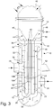
- FIGS 3 and 4 a second embodiment of the shell-and-tube heat exchanger 10 for process gas according to the present invention is schematically shown.
- This second embodiment of the heat exchanger 10 is almost identical to the first one described above, except for:
- Inlet 28 and outlet 30 nozzles of the first pressure chamber 12 are located on said first pressure chamber 12 preferably in between the tube-sheet 16 and the U-bends 20 e.g. in a region midways between the tube-sheet 16 and the U-bends 20.
- the first end 54 of the outer guiding jacket 22, i.e. the end of the outer guiding jacket 22 which is facing away from and far from the tube-sheet 16, is thus provided with an opening 54 that is in communication with the gap 32.
- the heat exchanger 10 shown in figure 3 works in the following way.
- the inlet hot medium enters into the outer guiding jacket 22, from the inlet nozzle 28 and by means of the connection conduit 34, in a point that is located in between the tube-sheet 16 and the U-bends 20. Since the outer guiding jacket 22 is provided with two openings 36 and 54, the inlet hot medium splits into two portions, flowing respectively towards the first (upper) opening 36 and the second (lower) opening 54 of the outer guiding jacket 22. Both fluid portions cross the tube bundle, in opposite directions, and exchange heat with the cooling medium flowing on tube-side, except for the portion of tubes 18 surrounded by the inner guiding jacket 24.
- the two fluid portions exiting from the first (upper) opening 36 and the second (lower) opening 54 are cooled, then they make a U-turn and enters into the gap 32 and both portions move towards the outlet nozzle 30. Two media are therefore contacted according to:
- the outer guiding jacket 22, near the connection conduit 34 with the inlet nozzle 28, can be sealed or not. If not sealed, the outer guiding jacket 22 can be provided, near the connection conduit 34, with a regulating device (not shown) for intentionally bypassing a specific amount of the hot medium from the inlet nozzle 28 to the gap 32. Such a bypass device is useful to control the hot medium temperature at the outlet nozzle 30.
- the heat exchanger 10 shown in figures 3 and 4 works in the same way as the first embodiment of the heat exchanger 10 shown in figures 1 and 2 , respectively.
- the shell-and-tube heat exchanger 10 has a one pass configuration on the tube bundle. In one aspect, the shell-and-tube heat exchanger 10 has a two passes configuration on the tube-side.
- the tube bundle may be one pass on shell-side.
- the first fluid may flow across the tube bundle by one pass.
- the tube bundle may be two passes on tube-side.
- the second fluid may flow through the tube bundle by two passes.
- said first fluid and said second fluid are not contacted according to a pure counter-current flows configuration.
- the cooling medium is a vaporizing medium introduced into the heat exchanger 10 at, or near at, saturation conditions and flowing under natural or forced circulation.
- the cooling medium is a non-vaporizing medium and the temperature at the heat exchanger 10 outlet is above the temperature of the hot medium at the heat exchanger 10 outlet.
- FIG 6 a third embodiment of the shell-and-tube heat exchanger 10 for process gas according to the present invention is schematically and partially shown.
- the U-bends 20 of the U-shaped tubes 18, connected to the first legs 18A and the second legs 18B of said tubes 18, are surrounded by a terminal guiding jacket 56 housed in the first pressure chamber 12.
- the terminal guiding jacket 56 thus prevents, or reduces, the hot medium flow across the U-bends 20.
- the terminal guiding jacket 56 is preferably in the form of a partly spherical or partly pseudo-spherical shell, such as a semi-spherical shell.
- the terminal guiding jacket 56 can be provided with one or more additional insulating layers, also of "sandwich" type.
- the terminal guiding jacket 56 can be adopted both in case the vaporization of the cooling medium must be avoided in the U-bends 20, and in case there is risk of vibrations of said U-bends 20 due to the hot medium flow.
- a bypass valve 68 is installed in a bypass conduit 70 obtained on the connection conduit 34 between the inlet nozzle 28 and the outer guiding jacket 22.
- the bypass valve 68 is configured for directly delivering to the gap 32 at least one part 72 of the fluid that enters from the inlet nozzle 28.
- said part 72 of the fluid does not enter the outer guiding jacket 22, whereas it is mixed, at the bypass valve 68, with another part 74 of fluid exiting from said outer guiding jacket 22 and flowing through the gap 32.
- FIGS 8A-8C three respective embodiments of the inner guiding jacket 24 are schematically shown. More specifically, in figure 8A the inner guiding jacket 24 is provided with an insulating layer 58 on at least part of the surface thereof, preferably the internal surface thereof, i.e. the surface facing the U-tubes first legs 18A surrounded by said inner guiding jacket 24. Thus, the internal surface of the inner guiding jacket 24 is the surface facing the first portion 18A of each U-shaped exchanging tube 18 surrounded by said inner guiding jacket 24.
- the inner guiding jacket 24 is provided with a double wall, i.e. with its own first wall and a second wall 60. The first wall and the second wall 60 are arranged at a distance from each other.
- the inner guiding jacket is arranged with its own first wall facing outwardly and with the second internal wall 60 facing the U-tubes first legs 18A surrounded by said inner guiding jacket 24, forming a gap in between the two walls where the hot medium flow is prevented.
- the inner guiding jacket 24 may be provided with a first wall facing outwardly and with a second internal wall 60 facing the first portion 18A of each U-shaped exchanging tube 18 surrounded by the inner guiding jacket 24.
- the inner guiding jacket 24 is provided both with the insulating layer 58 and the second wall 60 in a "sandwich" configuration, i.e. with the insulating layer 58 interposed between the, first wall of the inner guiding jacket 24 and the second wall 60 thereof.
- the inner guiding jacket 24 may be provided both with an insulating layer 58 on at least part of the surface thereof and with a first wall and a second wall 60, wherein said insulating layer 58 is interposed between said first wall and said second wall 60, i.e. in a "sandwich" configuration.
- the inner guiding jacket 24 may be provided both with an insulating layer 58 on at least part of the internal surface thereof, and with a first wall facing outwardly and a second internal wall 60 facing said first portion 18A of each U-shaped exchanging tube 18 surrounded by said inner guiding jacket 24, wherein said insulating layer 58 is interposed between said first outer wall and said second internal wall 60, i.e. in a "sandwich” configuration.
- These three alternative basic embodiments of the inner guiding jacket 24 can reduce or eliminate heat transfer from hot medium to cooling medium due to possible conduction or radiation.
- FIGS 9 and 10 two respective alternative versions of the shell-and-tube heat exchangers of figures 1 to 4 are shown.
- the difference consist in the fact that the outer guiding jacket 22 and the gap 32 are replaced by at least a layer 76 of an insulating material (refractory) that extends along the major longitudinal axis of the first pressure chamber 12.
- the layer 76 of an insulating material surrounds both a length portion, preferably most length, of the tube bundle and a length portion, preferably most length, of the inner guiding jacket 24.
- the layer 76 of an insulating material may surround a major length portion of the tube bundle.
- the layer 76 of an insulating material may surround a major length portion, of the inner guiding jacket 24.
- the layer 76 of an insulating material thus protects the first pressure chamber 12 from hot medium.
- heat exchanger 10 can be provided with structural supports 62 and other equipment, like manholes and instruments nozzles, that are not included in the scope of protection of the present invention.
- the shell-and-tube heat exchanger of the present invention thus conceived is susceptible in any case of numerous modifications and variants, all falling within the same inventive concept; in addition, all the details can be substituted by technically equivalent elements.
- the materials used, as well as the shapes and size can be of any type according to the technical requirements.
Landscapes
- Engineering & Computer Science (AREA)
- Physics & Mathematics (AREA)
- Thermal Sciences (AREA)
- Mechanical Engineering (AREA)
- General Engineering & Computer Science (AREA)
- Heat-Exchange Devices With Radiators And Conduit Assemblies (AREA)
Abstract
Description
- The present invention refers to a shell-and-tube heat exchanger and, more specifically, to a shell-and-tube heat exchanger designed to operate with hot process gases. Such a heat exchanger is designed for cooling a hot medium either by a vaporizing cooling medium or by a non-vaporizing cooling medium with a temperature cross with regard to the hot medium.
- In process and power industry, process and working media discharged at high temperature and pressure from chemical reactors, furnaces or heat exchangers must often be cooled by means of specifically designed heat exchangers. These heat exchangers are characterized by special heat exchange configurations and technological design.
- Hot medium discharged from chemical reactors operating in processes like steam methane reforming, ammonia synthesis, coal/biomass gasification, sulphur burning and ammonia oxidation is a major example of a medium at high temperature and pressure which must be cooled down in a special heat exchanger. Hot medium temperature and pressure can approximately range from 400°C to 1000°C and from 0.3 MPa to 30 MPa, respectively. Moreover, the hot medium can harm common construction metallic materials due to some aggressive chemical species like hydrogen, nitrogen, ammonia, carbon monoxide and sulphur oxides.
- Due to high temperatures and large flow rates of the hot medium, a wide range of heat removal, from few to tens of megawatt, is usually necessary. In order to perform such a strong cooling, special heat exchangers for the indirect heat exchange between the hot medium and a cooling medium are used.
- Such heat exchangers get several common names depending on the industrial process and cooling medium. For instance, a non-exhaustive list of more common heat exchangers used for cooling a hot medium comprises:
- process boilers or waste heat boilers in case the cooling medium is vaporizing water;
- boiler water pre-heaters in case the cooling medium is sub-cooled boiler water;
- steam super-heaters in case the cooling medium is steam;
- synthesis loop boilers in case the hot medium is discharged from an ammonia converter reactor and is cooled by vaporising water;
- vapour generators or evaporators in case of a vaporizing cooling fluid;
- process coolers in case of a generic cooling medium.
- Heat exchangers for cooling hot media are frequently of shell-and-tube type, with the hot medium flowing either on the shell-side or the tube-side, with vertical or horizontal installation. Exchanging tubes can be of different type, like straight tubes, U-shaped tubes or coiled tubes. The hot medium and the cooling medium can be indirectly contacted according to different configurations, like co-current flows, counter-current flows and cross-flow, and according to one pass or multi-passes.
- Many shell-and-tube type heat exchangers for cooling a medium at high temperature and pressure are known in the state of the art. Some examples of these shell-and-tube type heat exchangers, with specific reference to a process gas, are listed hereinafter.
- Document
US 4287944 describes a vertical process gas boiler wherein a hot process gas flowing on the shell-side indirectly exchanges heat with vaporising water flowing on tube-side and circulating under natural draft. The exchanger is one pass on shell-side and two passes on tube-side. The exchanger housing or shell is internally lined by an insulating material for protecting the shell walls from overheating. The tube bundle consists of U-tubes connected to a common tube-sheet, which separates the exchanger shell from the water-plenum. The water-plenum is split into two chambers, one collecting the water-and-steam mixture from the tube bundle and the other releasing fresh water to the tube bundle. The descending leg of the U-tubes is provided with an inner tube that is in communication with the chamber of fresh water. The inner tube ends shortly before the U-bends with an open end. Such an inner tube feeds the tube bundle with fresh water. - This configuration is claimed to be effective to prevent disturbances on natural circulation, since the vaporization of water in the descending leg occurs in the annulus between the U-tube and the inner tube, and not in the inner tube. Therefore, the steam produced in the annulus is claimed to be discharged into the water-and-steam chamber rather than be dragged into the U-tubes. On the other hand, this configuration is characterized by two potential drawbacks. Firstly, fresh water from the inner tube can be drafted-up in the annulus rather than to proceed in the U-tubes. Secondly, U-tubes have an intermediate welding.
- Document
US 4010797 describes a heat exchanger wherein the shell encloses a tube bundle, preferably with U-shaped tubes, and a shroud which forms, together with the shell, an annular gap and which surrounds most portion of the tube bundle. A hot process gas flows on shell-side and the cooling medium, preferably steam or water, flows on tube-side. A hot gas inlet nozzle is installed far from the tube-sheet and is in communication with the tube bundle. The hot gas firstly flows across the tube bundle in one-pass and then, after cooling, exits from the tube bundle and flows back in the gap. Accordingly, the tube-sheet and the shell are not in contact with the inlet hot gas. However, the exchanger is not capable of handling a temperature cross between the two media, or is not suitable for vaporizing water under natural circulation. - Document
EP 2482020 describes a heat exchanger, particularly designed for cooling a process gas, with the hot medium on tube-side and the cooling medium on shell-side. The exchanger has U-shaped tubes, with inner tubes installed in the U-shaped tube legs inletting the hot medium for a partial length of the leg. The exchanger design is claimed to keep the tube-sheet at moderate operating temperature. - Document
US 4561496 describes a process gas heat exchanger wherein a hot gas flowing on tube-side is cooled through vaporizing water circulating on shell-side. The shell is split into two chambers by internal walls. One chamber contains vaporizing water and the other chamber contains sub-cooled water. As a consequence, on the shell-side, two different cooling streams cross the tube bundle. The internal walls split the shell so as to surround one set of legs of the U-shaped tubes. The surrounded set of legs indirectly exchanges heat from hot gas to sub-cooled water, whereas the remaining portion of tubes indirectly exchange heat from hot gas to vaporising water. - Document
US 4907643 describes a process gas steam super-heater with U-shaped tubes, wherein the hot process gas flows on shell-side and the cold steam flows on tube-side. The shell-side is provided with a guiding jacket (shroud) which extends most of the tube bundle and forms a gap in between shell and shroud, so as to keep the shell swept by the cooled gas which exits from the shroud. The exchanger has one heat exchange pass on shell-side and two heat exchange passes on tube-side. The exchanger can properly work if there is no temperature cross between the cold and hot media. - Document
US 5915465 describes a process gas steam super-heater wherein hot process gas and cold steam flow on shell-side and tube-side respectively. The tube bundle consists of U-shaped tubes and the heat exchange is obtained with two passes on both shell-side and tube-side. By means of internal guiding jackets conveying the hot gas along a tortuous path, the two media are indirectly contacted in pure counter-current or pure co-current configuration. The cooled gas sweeps the shell before leaving the exchanger; yet, a portion of the tube-sheet is exposed to the inlet hot gas. - Document
WO 2017/001147 describes a process gas heat exchanger wherein the hot process gas flows on shell-side and the cooling medium flows on tube-side. The shell is internally equipped with a guiding jacket, surrounding most length of the tube bundle, which forms a gap in between the shell and the jacket. In such gap, the cooled gas is conveyed after the cooling. The tube bundle consists of tubes of bayonet type. - Document
EP 1610081 describes a heat exchanger, particularly designed for cooling a process gas by steam superheating, wherein the hot medium flows on tube-side and the cooling medium flows on shell-side. The exchanger has two concentric tube bundles, consisting of U-shaped tubes, made by different materials. On the shell-side, guiding jackets define two partially separated areas, wherein one area works at high temperature and relevant to one of the two tube bundles, and the other area works at low temperature and relevant to the other tube bundle. The exchanger is two-passes on shell-side and four-passes on tube-side. The exchanger may be not suitable in case the two media have a temperature cross and the inlet hot medium is in contact with the tubesheet. - Document
US 3749160 describes a heat exchanger for heat treatment of gas, wherein the gas to be treated can flow either on tube-side or on shell-side. The exchanger has U-shaped tubes and a mantle, installed internally to the shell, that surrounds most length of the tube bundle and that forms an annular gap with the shell. The mantle has both ends open. The shell-side gas enters into the mantle approximately at the mid length of the tube bundle and splits into two portions which cross the tube bundle in opposite directions. The two portions exit from the two ends of the shell and flow in the gap towards the outlet shell-side nozzle. When the shell-side gas is the hotter one and must be cooled, the shell is therefore swept by the cooled gas. The exchanger has one heat exchange pass on shell-side and two heat exchange passes on tube-side. The exchanger may not properly work if the two media have a temperature cross. - Other relevant heat exchangers, particularly suitable for cooling a hot liquid metal or a hot fluid coming from a nuclear reactor, are described in open literature. For example, document
US 3187807 describes a vertical heat exchanger mainly comprising a pressure vessel, a two-passes tube bundle, two separated tube-sheets for each tube-pass, installed in the upper part of the vessel, and two baffles, extending along the tubes and concentrically arranged, forming an inner and an outer chamber so that the first and the second tube-passes are positioned into the inner and the outer chambers respectively. The hot medium flows on the outer chamber side and the cooling medium flows on tube-side. Since the hot medium inlet is located in the upper part of the vessel, the heat transfer from hot and to cold media occurs via counter-flow or cross-flow. With such a configuration, the tube-sheet of the second tube-pass and an upper part of the vessel are in contact with the inlet hot medium, which can lead to a problematic design in case of high inlet temperatures. - Document
US 3545536 describes a shell-and-tube heat exchanger with U-shaped tubes, wherein the hot and cooling media flow on shell-side and tube-side respectively. The exchanger is two-passes both on tube-side and shell-side by means of a baffle installed in the shell forming two sections, one for the first tube-pass and the other for the second tube-pass. The heat transfer from shell-side to tube-side occurs via co-current flow. DocumentUS 3545536 focuses on a device for protecting the inlet portion of the first tube-pass from overheating or high heat flux due to the perpendicular impingement of the shell-side inlet medium on tubes. The device mainly consists of a collar, or sleeve, mounted on each tube and of a plate where the sleeves are connected to. Accordingly, the portion of the tube-sheet and of the inlet tubes of the first tube-pass are not in direct contact with the inlet shell-side hot medium. - Document
US 3437077 describes a once-through vapour generator of shell-and-tube type, with U-shaped tubes concentrically arranged, wherein the hot and the cooling media flow on tube-side and shell-side respectively. The shell is provided with internal guiding jackets and baffles which form two passageways on shell-side in order to vaporize and superheat in sequence the cooling medium. - As shown by the above documents, a large set of possible shell-and-tube heat exchanger configurations can be adopted for cooling a hot medium, in particular a hot process gas. The selection of the heat exchanger configuration, which includes, among others, the selection of the hot medium side and the tube bundle type, depends on several parameters and constraints. Broadly, the designer is usually interested in increasing the heat transfer performance, in extending the design life and in reducing the capital cost of the exchanger.
- In case the hot medium is installed on the shell-side, one major issue in designing a shell-and-tube heat exchanger is to avoid overheating and corrosion of shell walls. The above patent documents show that two major solutions can be adopted: the first solution consists in lining the internal shell walls by heat resistant materials (e.g.
US 4561496 ), whereas the second solution consists in sweeping the shell by the hot medium that had been previously cooled (e.g.US 5915465 ,US 4907643 ,WO 2017/001147 andUS3749160 ). - As for the selection of the exchanging tubes, U-shaped tubes or bayonet-tubes are often preferred, since thermal-mechanical constraints due to tubes elongation are easily absorbed. However, U-shaped tubes and bayonet-tubes are affected by two potential drawbacks:
- they involve a multi-passes heat exchange configuration on tube-side and therefore, in case of temperature cross between hot and cold media, the heat transfer performance and operating stability may be endangered;
- they are sensitive in case the cooling medium flowing on tube-side is a vaporizing medium, since vaporization may occur in all tube passes.
- In particular, beyond shell-and-tube heat exchanger configurations described in the above documents, two specific configurations realize to be problematic from design standpoint:
- A) a hot medium flows on shell-side, a vaporizing cooling medium flows on tube-side specially under natural circulation, the tube bundle is one pass on shell-side and two passes on tube-side, the exchanging tubes are of U-shape type. With such configuration, vaporization in both legs of the U-shaped tubes may occur. This is dangerous, since the vaporization in both legs disturbs the natural or forced circulation and therefore can stop or delay the cooling medium flow with subsequent overheating or corrosion of tubes. This is more critical during start-ups, shut-downs and change of operating loads;
- B) a hot medium flows on shell-side, a non-vaporizing cooling medium flows on tube-side, the tube bundle is one pass on shell-side and two passes on tube-side, the exchanging tubes are of U-shape type, a cross of hot and cooling media outlet temperatures occurs, hot and cold media are not contacted in a pure counter-current flow. With such configuration, the temperature cross is difficult to be prevented. As a consequence, the heat transfer performance and operating stability of the heat exchanger may significantly fall.
- On the other hand, configurations A) and B) are potentially interesting for heat exchange applications where a medium at high temperature and pressure must be cooled as:
- the U-shaped tubes effectively absorb the thermal elongation during any steady-state or transient load;
- the pressure drop of a hot medium flowing on shell-side can be easily adjusted and reduced by adjusting the tube bundle geometry;
- a tube bundle with one pass on shell-side involves a simple geometry and low pressure drops;
- when the cooling medium flows on tube-side, the operating metal temperature of tubes can be usually kept closer to cooling medium temperature, since the tube-side heat transfer coefficient is usually well higher than the heat transfer coefficient of the shell-side;
- vaporization of a medium is usually more efficient and stable on tube-side rather than on shell-side due to larger convective flow component and simpler flow path;
- it is competitive to install a temperature cross in a single heat exchanger if thermal performance and operating stability are not endangered by the cross;
- the hot medium pressure is often lower than the cooling medium one;
- the hot medium flowing on shell-side can be confined and conveyed by an internal guiding jacket so that the shell and the tube-sheet are swept by the hot medium after cooling, as described in some documents above.
- One object of the present invention is therefore to provide a shell-and-tube heat exchanger for process gas which is capable of resolving the above mentioned drawbacks of the prior art in a simple, inexpensive and particularly functional manner.
- In detail, one object of the present invention is to provide a shell-and-tube heat exchanger for process gas wherein the vaporization, in case the cooling medium is at saturation conditions, or a temperature cross, in case of non-vaporizing cooling medium, is prevented or at least minimized in at least a portion of the tubes of the tube bundle.
- Another object of the present invention is to provide a shell-and-tube heat exchanger for process gas which is capable of working always under stable and positive conditions from a thermal-hydraulic standpoint.
- These and other objects are achieved according to the present invention by providing a shell-and-tube heat exchanger for process gas as set forth in the attached claims.
- Further characteristics of the invention are underlined by the dependent claims, which are an integral part of the present description.
- In detail, a preferred embodiment of the shell-and-tube heat exchanger for process gas according to the present invention is characterized by the following technical features:
- it provides for an indirect heat exchange between a hot medium and a cooling medium;
- it is of shell-and-tube type;
- the tube bundle is one pass on shell-side and two passes on tube-side;
- the tubes have a U-shaped configuration, with the legs that can be straight or of any other shape (like helix);
- the hot medium flows on shell-side, whereas the cooling medium flows on tube-side;
- the cooling medium is a vaporizing medium flowing under natural or forced circulation, or a non-vaporizing medium having an outlet temperature that is above the hot medium outlet temperature (temperature cross);
- the hot and cooling media are not contacted in a pure counter-current configuration;
- on the shell-side there are two guiding jackets that convey the hot medium along the shell;
- the first shell-side guiding jacket, in communication with the hot medium inlet nozzle, surrounds most length of the tube bundle and most length of the second shell-side guiding jacket;
- the first shell-side guiding jacket forms a gap with the shell, said gap being in communication with the tube bundle and the hot medium outlet nozzle;
- the second shell-side guiding jacket, sealingly connected to the tube-sheet, totally or partially surrounds one set of the U-tubes legs and prevents, or reduces, the heat exchange between the two media for the portion of surrounded legs;
- ideally, the tube layout is of concentric type, with one set of legs installed in a circular central region of the tube-sheet and the other set of legs installed in a circular outer region surrounding the central region.
- The shell-and-tube heat exchanger for process gas according to the present invention is conceived to safely and efficiently works when the above configurations A) and B) are adopted. Actually, in configuration A), when a vaporizing medium is used as cooling medium, specially flowing under natural circulation, the inlet U-tubes legs (first tube-pass) do not participate, or minorly participate, to the heat exchange and therefore there is negligible vaporization in the inlet legs. As a consequence, the natural or forced circulation is always positively and steadily installed in the heat exchanger. Moreover, the tube-sheet and the shell are not in contact with the inlet hot medium.
- In configuration B), when a non-vaporizing medium is used as cooling medium, when the hot and cooling media are not contacted in a pure counter-current flows configuration, and when the cooling medium outlet temperature is higher than the outlet temperature of the hot medium, that is a temperature cross occurs within the exchanger, the portion of U-tubes legs where the temperature cross arises do not participate, or marginally participate, to heat exchange and therefore the temperature cross on the tube bundle is prevented. As a consequence, the heat transfer is always kept stable and with a positive performance. Moreover, the tube-sheet and the shell are not in contact with the inlet hot medium.
- The characteristics and advantages of a shell-and-tube heat exchanger for process gas according to the present invention will be clearer from the following exemplifying and non-limiting description, with reference to the enclosed schematic drawings, in which:
-
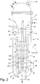
figures 1 and2 schematically show, in two respective operating conditions, a first embodiment of the shell-and-tube heat exchanger according to the present invention; -
figure 3 and4 schematically show, in two respective operating conditions, a second embodiment of the shell-and-tube heat exchanger according to the present invention; -
figure 5 is a cross-sectional view obtained in a middle portion of the shell-and-tube heat exchanger of anyfigure 1 to 4 ; -
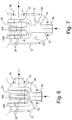
figure 6 schematically and partially shows a third embodiment of the shell-and-tube heat exchanger according to the present invention; -
figure 7 schematically and partially shows a fourth embodiment of the shell-and-tube heat exchanger according to the present invention; -
figures 8A-8C schematically show three respective embodiments of one of the guiding jackets of the shell-and-tube heat exchanger according to the present invention; -
figure 9 schematically shows the shell-and-tube heat exchanger offigures 1 and2 , provided with a different layout of its internal components; and -
figure 10 schematically shows the shell-and-tube heat exchanger offigures 3 and4 , provided with a different layout of its internal components. - With reference to figures, some embodiments of the shell-and-
tube heat exchanger 10 according to the present invention are shown. Theheat exchanger 10 has a cylindrical geometry and comprises afirst pressure chamber 12 and asecond pressure chamber 14 connected to a common tube-sheet 16 on opposite sides. The tube-sheet 16 is connected to a tube bundle comprising a plurality of U-shaped exchangingtubes 18 housed in thefirst pressure chamber 12. EachU-shaped tube 18 is provided with a first portion orleg 18A and with a second portion orleg 18B. Thefirst leg 18A and thesecond leg 18B of eachU-shaped tube 18 are hydraulically connected by a U-bend 20. Thefirst leg 18A and thesecond leg 18B of eachU-shaped tube 18 can be either straight or of other shape (like helix). Both ends of eachU-shaped tube 18 are connected to the tube-sheet 16. - A first fluid, i.e. a hot medium, flows in the
first pressure chamber 12, also called "shell", and a second fluid, i.e. the cooling medium, flows in thesecond pressure chamber 14, which is also called "channel". Thesecond pressure chamber 14 is in communication with theU-shaped tube 18. In other words, the hot medium flows on shell-side, and the cooling medium flows on tube-side. The shell-and-tube heat exchanger 10 is configured to guide the first fluid across a portion of the tube bundle before contacting the tube-sheet 16. The shell-and-tube heat exchanger 10 is configured to guide the first fluid across at least a portion of thesecond legs 18B of tube bundle before contacting the tube-sheet 16. Thus, the shell-and-tube heat exchanger 10 is configured to guide the first fluid such that the a portion of heat is exchanged between the first fluid and the second fluid before the first fluid contacts the tube-sheet 16. The first fluid is admitted into thefirst pressure chamber 12 in a point so that the first fluid flows towards the tube-sheet 16 by exchanging at least a portion of heat with the second fluid. - The
first pressure chamber 12 is provided with one or more hotmedium inlet nozzles 28 and with one or more hotmedium outlet nozzles 30.Inlet 28 andoutlet 30 nozzles are located far from the tube-sheet 16, preferably near or after the U-bends 20. That the first fluid is a hot medium or warmer medium means that the first fluid is warmer than the second fluid when fed to the heat exchanger, i.e. the first fluid is warmer when fed to the heat exchanger than the second fluid when fed to the heat exchanger. In other words, the first fluid is warmer when entering the heat exchanger through theinlet nozzle 28 than the second fluid is when entering the heat exchanger through thefirst nozzle 46 or thesecond nozzle 48. The second fluid is a cooling medium and can also be denoted cold medium. That the second fluid is a cold medium or colder medium means that the second fluid is colder than the first fluid when fed to the heat exchanger. The second fluid is colder when fed to the heat exchanger than the first fluid when fed to the heat exchanger. In other words, the second fluid is colder when entering the heat exchanger through thefirst nozzle 46 or thesecond nozzle 48 than the first fluid is when entering the heat exchanger through theinlet nozzle 28. - The
first pressure chamber 12 contains at least oneouter guiding jacket 22 and at least oneinner guiding jacket 24. Each outer 22 and inner 24 guiding jacket has a cylindrical or pseudo-cylindrical geometry and extends along the major longitudinal axis of thefirst pressure chamber 12. Theouter guiding jacket 22 extends until to or after the U-bends 20. Thefirst pressure chamber 12 also contains a plurality of baffles orgrids 26 that, together with the exchangingtubes 18, forms the tube bundle. - The
outer guiding jacket 22 and thefirst pressure chamber 12 form agap 32 in between. Thegap 32 is in communication with the hotmedium outlet nozzle 30. Theouter guiding jacket 22 surrounds both a length portion, preferably most length, i.e. a major length portion, of the tube bundle and a length portion, preferably most length, i.e. a major length portion, of theinner guiding jacket 24. The length portion of the tube bundle surrounded by the outer guidingjacket 22 preferably comprises the U-bends 20. Theouter guiding jacket 22 preferably surrounds a length portion of the tube bundle including the U-bends 20. Theouter guiding jacket 22, at a first end thereof which is facing away and far from the tube-sheet 16, is in communication with the hotmedium inlet nozzle 28 by means of aconnection conduit 34 and receives the hot medium from theinlet nozzle 28 at an opposite side of the U-bends 20 to the side where the tube bundle is connected to thetube sheet 16 or near the U-bends 20. In this context, the introducing the hot medium to the outer guidingjacket 22 at an opposite side of the U-bends 20 to the side where the tube bundle is connected to the tube-sheet 16 implies that the entry of the hot medium into the tube bundle does not occur in between the U-bends 20 and the tube-sheet 16. Theouter guiding jacket 22, at a second end thereof which is facing and near to the tube-sheet 16, has anopening 36 that is in communication with thegap 32. Theouter guiding jacket 22 may be configured to guide the first fluid across a portion of the tube bundle before contacting the tube-sheet 16. Theconnection conduit 34, which connects theinlet nozzle 28 with the outer guidingjacket 22, may be configured to guide the first fluid across a portion of the tube bundle before contacting the tube-sheet 16. - The joining portion between the
inlet nozzle 28 and theconnection conduit 34 of the outer guidingjacket 22 is preferably sealed. On the contrary, if no sealing is provided, the outer guidingjacket 22 can be provided, near theconnection conduit 34, with a regulating device (not shown) for intentionally bypassing a specific amount of the hot medium from theinlet nozzle 28 to thegap 32. Such a bypass is useful to control the hot medium temperature at theoutlet nozzle 30. - The
inner guiding jacket 24 totally surrounds the set of firstU-tubes legs 18A on azimuthal (circular) direction and surrounds on longitudinal direction said set of firstU-tubes legs 18A for at least part of their respective length. More specifically: - in case the cooling medium is a vaporizing fluid flowing under natural circulation, the
inner guiding jacket 24 totally, or almost totally, surrounds the set offirst legs 18A, i.e. thelegs 18A of thetubes 18 where the cooling medium enters (first tube-pass); - in case the cooling medium is a vaporizing fluid flowing under forced circulation, the
inner guiding jacket 24 totally or partially surrounds the set offirst legs 18A, i.e. thelegs 18A of thetubes 18 where the cooling medium enters (first tube-pass); - in case the cooling medium is a non-vaporizing fluid, inner guiding
jacket 24 partially surrounds the set offirst legs 18A, i.e. thelegs 18A of thetubes 18 where the cooling medium exits (second tube-pass). - The
inner guiding jacket 24, at a first end thereof which is facing and near to the tube-sheet 16, is sealingly connected to said tube-sheet 16 by first connection means 38. Theinner guiding jacket 24, at asecond end 52 thereof which is facing away and far from the tube-sheet 16, is preferably closed, except for through holes or windows for the passage of the firstU-tubes legs 18A. As a result, theinner guiding jacket 24 prevents the hot medium flow across the surrounded portion of the enclosedU-tubes legs 18A and therefore prevents, or reduces, the heat transfer from hot medium to cooling medium in said portion of theU-tubes legs 18A. Theinner guiding jacket 24, in other words, has the purpose to prevent, or reduce, for the surrounded portion of theU-tubes legs 18A, either the vaporization, in case the cooling medium is at saturation conditions, or a temperature cross, in case of non-vaporizing cooling medium. Alternatively, to the closedsecond end 52 of theinner guiding jacket 24, theinner guiding jacket 24 may be open at thesecond end 52, in which case there will be an at least partially stagnant zone within theinner guiding jacket 24, which reduces heat exchange between the second fluid in thefirst legs 18A and the first fluid. However, a closedsecond end 52 of theinner guiding jacket 24 is preferred. Thesecond end 52 may be provided with a plate having through holes or windows for the passage of the firstU-tubes legs 18A. The plate may be a perforated plate or a rigid plate except for the through holes or windows for the passage of the firstU-tubes legs 18A and possibly further equipment or devices. - The
second pressure chamber 14 contains a second pressurechamber guiding jacket 40 that separates thesecond pressure chamber 14 into afirst section 42 and asecond section 44 non-directly communicating with each other. Thesecond pressure chamber 14 is also provided with at least afirst nozzle 46 for inletting or outletting the cooling medium and with at least asecond nozzle 48 for outletting or inletting the cooling medium. The second pressurechamber guiding jacket 40 is connected to the tube-sheet 16 or to one set ofU-tubes legs section second pressure chamber 14 is in communication with one set ofU-tubes legs - Preferably, the
tube 18 layout is of concentric type as shown infigure 5 , with thefirst legs 18A arranged in a circular central portion of the tube-sheet 16 ("centre" 64, seefigure 5 ) and with thesecond legs 18B arranged in a circular portion surrounding the central portion of said tube-sheet 16 ("crown" 66, seefigure 5 ). As per such preferred tube layout, the followingheat exchanger 10 configuration can be preferably adopted: - the
inner guiding jacket 24 is concentrically installed inside thefirst pressure chamber 12 and surrounds thefirst legs 18A connected to the "centre" of the tube-sheet 16 regardless the cooling medium. Consequently, thefirst legs 18A represents the first tube-pass in case of vaporizing cooling medium and the second tube-pass in case of a non-vaporizing cooling medium; - the outer guiding
jacket 22 is concentrically installed inside thefirst pressure chamber 12 and surrounds most length of the tube bundle and most length of theinner guiding jacket 24; - the two
sections second pressure chamber 14 are concentrically arranged in saidsecond pressure chamber 14, wherein a firstinner section 42 is in fluid communication with thefirst legs 18A and a secondouter section 44 is in fluid communication with thesecond legs 18B; - in case of vaporizing cooling medium, the cooling medium enters into the
inner section 42 from afirst nozzle 46 of thesecond pressure chamber 14, then said cooling medium enters into thefirst legs 18A (first tube-pass), flows along thetubes 18, exits from thesecond legs 18B (second tube-pass), enters into theouter section 44 and then exits from thesecond nozzle 48 of thesecond pressure chamber 14; - in case of a non-vaporizing cooling medium, the cooling medium enters into the
outer section 44 from thesecond nozzle 48 of thesecond pressure chamber 14, then said cooling medium enters into thesecond legs 18B (first tube-pass), flows along thetubes 18, exits from thefirst legs 18A (second tube-pass), enters into theinner section 42 and then exits from thefirst nozzle 46 of thesecond pressure chamber 14. - In case the cooling medium is a vaporising medium flowing under natural circulation, the
heat exchanger 10 is preferably disposed in a vertical position (referring to the major longitudinal axis of its shell), with the tube bundle oriented downward. Otherwise, theheat exchanger 10 can be either vertical or horizontal regardless the orientation of the tube bundle. - On shell-side (i.e. the hot medium side), the
heat exchanger 10 shown infigure 1 works in the following way. The hot medium enters into the outer guidingjacket 22 from theinlet nozzle 28, then flows along the outer guidingjacket 22 towards the tube-sheet 16 by crossing the U-tubes 18, except for the portion of saidU-tubes 18 surrounded by theinner guiding jacket 24, according to the flow path defined by the baffles orgrids 26. Along the tube bundle, the hot medium indirectly releases heat to the cooling medium which flows in the U-tubes 18, except for the portion of saidU-tubes 18 surrounded by theinner guiding jacket 24. The two media are therefore contacted according to: - a pure, or almost pure, co-current configuration in case of vaporizing cooling medium in natural circulation;
- a pure, or almost pure, co-current configuration or both co-current and counter-current configurations in case of vaporizing cooling medium in forced circulation;
- both co-current and counter-current configurations in case of a non-vaporizing cooling medium which outlet temperature is higher than hot medium outlet temperature.
- Near the tube-
sheet 16, the hot medium exits from the outer guidingjacket 22 by theopening 36, makes a U-turn, enters into thegap 32 and then flows towards theoutlet nozzle 30, from which said hot medium exits from theheat exchanger 10. The hot medium exiting from theopening 36 has been cooled. Therefore, the portions of the tube-sheet 16 and thefirst pressure chamber 12, that are in contact with the hot medium, are swept by the cooled hot medium. In case an amount of inlet hot medium is bypassed before crossing the tube bundle, this amount of inlet hot medium is mixed with the cooled hot medium flowing in thegap 32 before leaving from theoutlet nozzle 30. - On tube-side (i.e. the cooling medium side), the
heat exchanger 10 works in the following way. In a first operating condition (figure 1 ) the cooling medium is a vaporizing medium flowing under natural circulation. Theheat exchanger 10, sometimes called process evaporator, vapour generator, process gas boiler or waste heat boiler depending on the hot and cooling media, is preferably in a vertical position, with the tube bundle directed downward. In case of the preferred concentric layout of the U-tubes 18, as shown infigure 5 , the vaporizing cooling medium at saturation conditions, or nearly at saturation conditions, is in liquid phase and enters into theinner section 42 of thesecond pressure chamber 14 from thefirst nozzle 46. The U-tubesfirst legs 18A of the tube-sheet 16central portion 64 are in communication with theinner section 42, whereas the U-tubessecond legs 18B of the tube-sheet 16 "crown" orperipheral portion 66 are in communication with theouter section 44 of thesecond pressure chamber 14. - The vaporizing cooling medium in the
inner section 42 enters into the U-tubesfirst legs 18A (first tube-pass) and flows down under natural circulation. Theinner guiding jacket 24 totally, or almost totally, surrounds the U-tubesfirst legs 18A to prevent, or reduces, the heat transfer from hot medium to cooling medium and therefore to prevent the vaporization in the U-tubesfirst legs 18A. At thesecond end 52 of theinner guiding jacket 24, the vaporizing cooling medium leaves the surrounded portion of the U-tubesfirst legs 18A and starts to exchange heat with the hot medium. Soon, the vaporizing cooling medium has a U-turn in the U-bends 20, then naturally moves upward in thesecond legs 18B (second tube-pass) where cooling of the hot medium by vaporization occurs. - As well known, a liquid fluid and its liquid-and-vapour mixture at same saturation temperature have different densities. Such a difference is the driving force for the natural circulation. The two-phase mixture exiting from the
second legs 18B is discharged into theouter section 44 of thesecond pressure chamber 14 and then leaves theheat exchanger 10 from thesecond nozzle 48. First 46 and second 48 nozzles of thesecond pressure chamber 14 can be connected to a separated and elevated equipment (not shown), commonly called liquid-and-vapour drum, which provides for required static head for natural circulation, for liquid-and-vapour separation and for liquid reservoir in case of shut-down. - Since the U-tubes
first legs 18A are adiabatic, or almost adiabatic, no significant vaporization occurs in the first tube-pass and therefore the natural circulation is not disturbed. Theheat exchanger 10 works always under stable and positive conditions form thermal-hydraulic standpoint. - In a second operating condition (
figure 1 ) the cooling medium is a vaporizing medium flowing under forced circulation. Once again theheat exchanger 10 is preferably in vertical position, with the tube bundle directed downward. In case of the preferred concentric layout of the U-tubes 18, as shown infigure 5 , the vaporizing cooling medium at saturation conditions, or nearly at saturation conditions, enters into theinner section 42 from thefirst nozzle 46 in liquid phase. The U-tubesfirst legs 18A of the tube-sheet 16central portion 64 are in communication with theinner section 42, whereas the U-tubessecond legs 18B of the tube-sheet 16 "crown" orperipheral portion 66 are in communication with theouter section 44 of thesecond pressure chamber 14. - The vaporising cooling medium in the
inner section 42 enters into the U-tubesfirst legs 18A (first tube-pass) and flows down under forced circulation. Theinner guiding jacket 24 totally, or partially, surrounds the U-tubesfirst legs 18A to prevent, or reduce, the heat transfer from hot medium to cooling medium and therefore to prevent the vaporization in the surrounded portion of the U-tubesfirst legs 18A. At thesecond end 52 of theinner guiding jacket 24, the vaporizing cooling medium leaves the surrounded portion of the U-tubesfirst legs 18A and starts to exchange heat with the hot medium. When the vaporising cooling medium arrives at the U-bends 20, it has a U-turn and moves upward in the U-tubessecond legs 18B (second tube-pass). The liquid-and-vapour mixture exiting from the U-tubessecond legs 18B is discharged into theouter section 44 of thesecond pressure chamber 14 and then leaves theheat exchanger 10 from thesecond nozzle 48. Also in this second operating condition the first 46 and second 48 nozzles of thesecond pressure chamber 14 can be connected to a separated equipment, commonly called liquid-and-vapour drum, which provides for liquid-and-vapour separation and for liquid reservoir in case of shut-down. - Since the U-tubes
first legs 18A are adiabatic, or partially adiabatic, the vaporization in the first tube-pass is eliminated, or reduced. This has a positive effect on forced circulation since the liquid in the first tube-pass contributes to natural draft. Such a contribution is more important, or even essential, in case of failure of the pumping device or during transients. - In a third operating condition (
figure 2 ) the cooling medium is a non-vaporizing medium which, at the heat exchanger outlet (first nozzle 46), has a temperature higher than outlet hot medium temperature (i.e. a temperature cross occurs). The cooling medium can be sub-cooled water, steam or any other fluid in vapour or liquid phase. In this operating condition theheat exchanger 10 can be commonly called water preheater, steam super-heater or cooler, respectively. In case of the preferred concentric layout of the U-tubes 18, as shown infigure 5 , the cooling medium enters into theouter section 44 from thesecond nozzle 48, and then enters into the U-tubessecond legs 18B (first tube-pass). The cooling medium flows along the U-tubessecond legs 18B, has a U-turn in the U-bends 20 and then flows in the U-tubesfirst legs 18A (second tube-pass). The cooling medium indirectly exchanges heat with the hot medium along the U-tubessecond legs 18B and in case of aninner guiding jacket 24 extending along a part of the length of thefirst legs 18A also a portion of thefirst legs 18A till to theinner guiding jacket 24. Subsequently, in thetube 18 portion between thesecond end 52 of theinner guiding jacket 24 and the tube-sheet 16, the U-tubesfirst legs 18A do not contribute to the heat exchange between the two media. The temperature of the cooling medium at thesecond end 52 of theinner guiding jacket 24 is equal to or lower than the hot medium temperature at this point of the tube-bundle. Therefore, the temperature cross is prevented. As a result, even if the temperature of the cooling medium is higher than the temperature of the hot medium at the heat exchanger outlet and the heat exchanger has not a pure counter-current configuration, the temperature cross along the tube-bundle is prevented and therefore the heat exchanger works always under stable and positive performance from thermal standpoint. - In
figures 3 and4 a second embodiment of the shell-and-tube heat exchanger 10 for process gas according to the present invention is schematically shown. This second embodiment of theheat exchanger 10 is almost identical to the first one described above, except for: - the outer guiding
jacket 22 has the two ends both open; - the inlet hot medium is admitted into the outer guiding
jacket 22 in a point in between the tube-sheet 16 and the U-bends 20, e.g. in a point within a region midways between the tube-sheet 16 and the U-bends 20; - the hot medium splits in two portions across the tube bundle.
-
Inlet 28 andoutlet 30 nozzles of thefirst pressure chamber 12 are located on saidfirst pressure chamber 12 preferably in between the tube-sheet 16 and the U-bends 20 e.g. in a region midways between the tube-sheet 16 and the U-bends 20. Thefirst end 54 of the outer guidingjacket 22, i.e. the end of the outer guidingjacket 22 which is facing away from and far from the tube-sheet 16, is thus provided with anopening 54 that is in communication with thegap 32. - On shell-side (i.e. the hot medium side), the
heat exchanger 10 shown infigure 3 works in the following way. The inlet hot medium enters into the outer guidingjacket 22, from theinlet nozzle 28 and by means of theconnection conduit 34, in a point that is located in between the tube-sheet 16 and the U-bends 20. Since the outer guidingjacket 22 is provided with twoopenings opening 54 of the outer guidingjacket 22. Both fluid portions cross the tube bundle, in opposite directions, and exchange heat with the cooling medium flowing on tube-side, except for the portion oftubes 18 surrounded by theinner guiding jacket 24. The two fluid portions exiting from the first (upper) opening 36 and the second (lower)opening 54 are cooled, then they make a U-turn and enters into thegap 32 and both portions move towards theoutlet nozzle 30. Two media are therefore contacted according to: - both co-current and counter-current configurations in case of vaporizing cooling medium flowing under natural or forced circulation;
- both co-current and counter-current configurations in case of a non-vaporizing cooling medium which outlet temperature is higher than hot medium outlet temperature.
- The
outer guiding jacket 22, near theconnection conduit 34 with theinlet nozzle 28, can be sealed or not. If not sealed, the outer guidingjacket 22 can be provided, near theconnection conduit 34, with a regulating device (not shown) for intentionally bypassing a specific amount of the hot medium from theinlet nozzle 28 to thegap 32. Such a bypass device is useful to control the hot medium temperature at theoutlet nozzle 30. - On tube-side (i.e. the cooling medium side), the
heat exchanger 10 shown infigures 3 and4 works in the same way as the first embodiment of theheat exchanger 10 shown infigures 1 and2 , respectively. - In one aspect, the shell-and-
tube heat exchanger 10 has a one pass configuration on the tube bundle. In one aspect, the shell-and-tube heat exchanger 10 has a two passes configuration on the tube-side. The tube bundle may be one pass on shell-side. The first fluid may flow across the tube bundle by one pass. The tube bundle may be two passes on tube-side. The second fluid may flow through the tube bundle by two passes. - In one aspect, said first fluid and said second fluid are not contacted according to a pure counter-current flows configuration.
- In one aspect, the cooling medium is a vaporizing medium introduced into the
heat exchanger 10 at, or near at, saturation conditions and flowing under natural or forced circulation. - In one aspect, the cooling medium is a non-vaporizing medium and the temperature at the
heat exchanger 10 outlet is above the temperature of the hot medium at theheat exchanger 10 outlet. - In
figure 6 a third embodiment of the shell-and-tube heat exchanger 10 for process gas according to the present invention is schematically and partially shown. In this embodiment the U-bends 20 of theU-shaped tubes 18, connected to thefirst legs 18A and thesecond legs 18B of saidtubes 18, are surrounded by aterminal guiding jacket 56 housed in thefirst pressure chamber 12. Theterminal guiding jacket 56 thus prevents, or reduces, the hot medium flow across the U-bends 20. Theterminal guiding jacket 56 is preferably in the form of a partly spherical or partly pseudo-spherical shell, such as a semi-spherical shell. Theterminal guiding jacket 56 can be provided with one or more additional insulating layers, also of "sandwich" type. Theterminal guiding jacket 56 can be adopted both in case the vaporization of the cooling medium must be avoided in the U-bends 20, and in case there is risk of vibrations of saidU-bends 20 due to the hot medium flow. - In
figure 7 a fourth embodiment of the shell-and-tube heat exchanger 10 for process gas according to the present invention is schematically and partially shown. In this embodiment abypass valve 68 is installed in abypass conduit 70 obtained on theconnection conduit 34 between theinlet nozzle 28 and the outer guidingjacket 22. Thebypass valve 68 is configured for directly delivering to thegap 32 at least onepart 72 of the fluid that enters from theinlet nozzle 28. In other words, saidpart 72 of the fluid does not enter the outer guidingjacket 22, whereas it is mixed, at thebypass valve 68, with anotherpart 74 of fluid exiting from said outer guidingjacket 22 and flowing through thegap 32. - In
figures 8A-8C three respective embodiments of theinner guiding jacket 24 are schematically shown. More specifically, infigure 8A theinner guiding jacket 24 is provided with an insulatinglayer 58 on at least part of the surface thereof, preferably the internal surface thereof, i.e. the surface facing the U-tubesfirst legs 18A surrounded by saidinner guiding jacket 24. Thus, the internal surface of theinner guiding jacket 24 is the surface facing thefirst portion 18A of each U-shaped exchangingtube 18 surrounded by saidinner guiding jacket 24. Infigure 8B theinner guiding jacket 24 is provided with a double wall, i.e. with its own first wall and asecond wall 60. The first wall and thesecond wall 60 are arranged at a distance from each other. The inner guiding jacket is arranged with its own first wall facing outwardly and with the secondinternal wall 60 facing the U-tubesfirst legs 18A surrounded by saidinner guiding jacket 24, forming a gap in between the two walls where the hot medium flow is prevented. Thus, theinner guiding jacket 24 may be provided with a first wall facing outwardly and with a secondinternal wall 60 facing thefirst portion 18A of each U-shaped exchangingtube 18 surrounded by theinner guiding jacket 24. Infigure 8C theinner guiding jacket 24 is provided both with the insulatinglayer 58 and thesecond wall 60 in a "sandwich" configuration, i.e. with the insulatinglayer 58 interposed between the, first wall of theinner guiding jacket 24 and thesecond wall 60 thereof. Thus, theinner guiding jacket 24 may be provided both with an insulatinglayer 58 on at least part of the surface thereof and with a first wall and asecond wall 60, wherein said insulatinglayer 58 is interposed between said first wall and saidsecond wall 60, i.e. in a "sandwich" configuration. Further, theinner guiding jacket 24 may be provided both with an insulatinglayer 58 on at least part of the internal surface thereof, and with a first wall facing outwardly and a secondinternal wall 60 facing saidfirst portion 18A of each U-shaped exchangingtube 18 surrounded by saidinner guiding jacket 24, wherein said insulatinglayer 58 is interposed between said first outer wall and said secondinternal wall 60, i.e. in a "sandwich" configuration. These three alternative basic embodiments of theinner guiding jacket 24 can reduce or eliminate heat transfer from hot medium to cooling medium due to possible conduction or radiation. - In
figures 9 and10 two respective alternative versions of the shell-and-tube heat exchangers offigures 1 to 4 are shown. The difference consist in the fact that the outer guidingjacket 22 and thegap 32 are replaced by at least alayer 76 of an insulating material (refractory) that extends along the major longitudinal axis of thefirst pressure chamber 12. Thelayer 76 of an insulating material surrounds both a length portion, preferably most length, of the tube bundle and a length portion, preferably most length, of theinner guiding jacket 24. Thelayer 76 of an insulating material may surround a major length portion of the tube bundle. Thelayer 76 of an insulating material may surround a major length portion, of theinner guiding jacket 24. Thelayer 76 of an insulating material thus protects thefirst pressure chamber 12 from hot medium. - Finally, all the embodiments of the
heat exchanger 10 can be provided withstructural supports 62 and other equipment, like manholes and instruments nozzles, that are not included in the scope of protection of the present invention. - It is thus seen that the shell-and-tube heat exchanger according to the present invention achieves the previously outlined objects.
- The shell-and-tube heat exchanger of the present invention thus conceived is susceptible in any case of numerous modifications and variants, all falling within the same inventive concept; in addition, all the details can be substituted by technically equivalent elements. In practice, the materials used, as well as the shapes and size, can be of any type according to the technical requirements.
- The scope of protection of the invention is therefore defined by the enclosed claims.
Claims (16)
- Shell-and-tube heat exchanger (10) having a cylindrical geometry and comprising a first pressure chamber (12) and a second pressure chamber (14) connected to a common tube-sheet (16) on opposite sides, wherein the first pressure chamber (12) is provided with at least an inlet nozzle (28) for inletting a first fluid and with at least an outlet nozzle (30) for outletting the first fluid, wherein the second pressure chamber (14) is provided with at least a first nozzle (46) for inletting or outletting a second fluid and with at least a second nozzle (48) for outletting or inletting, respectively, the second fluid, wherein the tube-sheet (16) is connected to a tube bundle housed in the first pressure chamber (12) and comprising a plurality of U-shaped exchanging tubes (18) through which the second fluid flows to indirectly perform heat exchange with the first fluid, wherein each U-shaped exchanging tube (18) is provided with a first portion (18A) and with a second portion (18B), wherein the first portion (18A) and the second portion (18B) of each U-shaped exchanging tube (18) are hydraulically connected by a U-bend (20), the shell-and-tube heat exchanger (10) being characterized in that the first pressure chamber (12) contains at least one inner guiding jacket (24) having a cylindrical or pseudo-cylindrical geometry and extending along the major longitudinal axis of said first pressure chamber (12), said inner guiding jacket (24) surrounding said first portion (18A) of each U-shaped exchanging tube (18) for at least part of the respective length of said first portion (18A), said inner guiding jacket (24) being sealingly connected, at a first end thereof, to the tube-sheet (16) by first connection means (38), said inner guiding jacket (24) being configured to prevent the first fluid flow across said first portion (18A) of each U-shaped exchanging tube (18), therefore preventing, or reducing, the heat transfer from the first fluid to the second fluid in said first portion (18A) of each U-shaped exchanging tube (18).
- Shell-and-tube heat exchanger (10) according to claim 1, characterized in that the shell-and-tube heat exchanger (10) has a one pass configuration over the tube bundle on the shell side, preferably the shell-and-tube heat exchanger (10) has a two passes configuration on the tube side.
- Shell-and-tube heat exchanger (10) according to claim 1 or 2, characterized in that the shell-and-tube heat exchanger (10) is configured to guide the first fluid across a portion of the tube bundle before contacting the tube-sheet (16).
- Shell-and-tube heat exchanger (10) according to anyone of claims 1 to 3, characterized in that the first pressure chamber (12) also contains at least one outer guiding jacket (22) having a cylindrical or pseudo-cylindrical geometry and extending along the major longitudinal axis of said first pressure chamber (12), said outer guiding jacket (22) surrounding both a length portion of the tube bundle and a length portion of the inner guiding jacket (24).
- Shell-and-tube heat exchanger (10) according to claim 4, characterized in that said outer guiding jacket (22) and the first pressure chamber (12) form a gap (32) in between, said gap (32) being in communication with the first fluid outlet nozzle (30).
- Shell-and-tube heat exchanger (10) according to claim 4 or 5, characterized in that said outer guiding jacket (22), at a first end thereof which is facing away from the tube-sheet (16), is in communication with the first fluid inlet nozzle (28) by means of a connection conduit (34), whereas said outer guiding jacket (22), at a second end thereof which is facing the tube-sheet (16), has an opening (36) that is in communication with said gap (32).
- Shell-and-tube heat exchanger (10) according to claim 4 or 5, characterized in that said outer guiding jacket (22), at a first end thereof which is facing away from the tube-sheet (16), is provided with a first opening (54) that is in communication with said gap (32), whereas said outer guiding jacket (22), at a second end thereof which is facing the tube-sheet (16), has a second opening (36) that is in communication with said gap (32), wherein said outer guiding jacket (22) is in communication with the first fluid inlet nozzle (28) by means of a connection conduit (34) in a point located in between said first opening (54) and said second opening (36).
- Shell-and-tube heat exchanger (10) according to anyone of claims 1 to 3, characterized in that the first pressure chamber (12) also contains at least a layer (76) of an insulating material extending along the major longitudinal axis of said first pressure chamber (12), said at least a layer (76) of an insulating material surrounding both a length portion of the tube bundle and a length portion of the inner guiding jacket (24).
- Shell-and-tube heat exchanger (10) according to anyone of claims 1 to 8, characterized in that the U-bends (20) of the U-shaped exchanging tubes (18) are surrounded by a terminal guiding jacket (56) housed in the first pressure chamber (12), said terminal guiding jacket (56) being configured to prevent flow of the first fluid across said U-bends (20).
- Shell-and-tube heat exchanger (10) according to anyone of claims 1 to 9, characterized in that the inner guiding jacket (24) is provided with an insulating layer (58) on at least part of the surface thereof.
- Shell-and-tube heat exchanger (10) according to anyone of claims 1 to 10, characterized in that the inner guiding jacket (24) is provided with a first wall and a second internal wall (60) arranged at a distance from each other.
- Shell-and-tube heat exchanger (10) according to anyone of claims 1 to 11, characterized in that the second pressure chamber (14) is provided with a second pressure chamber guiding jacket (40) that separates said second pressure chamber (14) into a first section (42) and a second section (44) non-directly communicating with each other, wherein said second pressure chamber guiding jacket (40) is connected to the tube-sheet (16) or to one of said first portion (18A) or said second portion (18B) of each U-shaped exchanging tube (18) by second connection means (50).
- Shell-and-tube heat exchanger (10) according to claim 12, characterized in that said first section (42) and said second section (44) are concentrically arranged in said second pressure chamber (14), wherein said first section (42) is in fluid communication with said first portion (18A) of each U-shaped exchanging tube (18) and said second section (44) is in communication with said second portion (18B) of each U-shaped exchanging tube (18).
- Shell-and-tube heat exchanger (10) according to anyone of claims 1 to 13, characterized in that the U-shaped exchanging tubes (18) have a layout of concentric type, wherein the first portions (18A) of said U-shaped exchanging tubes (18) are arranged in a circular central portion (64) of the tube-sheet (16) and wherein the second portions (18B) of said U-shaped exchanging tubes (18) are arranged in a circular peripheral portion (66) of said tube-sheet (16) surrounding said circular central portion (64).
- Shell-and-tube heat exchanger (10) according to anyone of claims 1 to 14, characterized in that said first fluid flowing into the first pressure chamber (12), that is the shell-side of the heat exchanger (10), is a hot medium, whereas said second fluid flowing into said second pressure chamber (14) and said U-shaped exchanging tubes (18) of the tube bundle, that is the tube-side of the heat exchanger (10), is a cooling medium.
- Shell-and-tube heat exchanger (10) according to anyone of claims 1 to 15, characterized in that said first fluid and said second fluid are not contacted according to a pure counter-current flows configuration.
Priority Applications (8)
| Application Number | Priority Date | Filing Date | Title |
|---|---|---|---|
| DK17425056.3T DK3406999T3 (en) | 2017-05-26 | 2017-05-26 | SMOKE PART HEAT EXCHANGER |
| EP17425056.3A EP3406999B1 (en) | 2017-05-26 | 2017-05-26 | Shell-and-tube heat exchanger |
| ES17425056T ES2842423T3 (en) | 2017-05-26 | 2017-05-26 | Shell and Tube Heat Exchanger |
| US16/616,674 US11054196B2 (en) | 2017-05-26 | 2018-04-26 | Shell-and-tube heat exchanger |
| PCT/EP2018/060722 WO2018215160A1 (en) | 2017-05-26 | 2018-04-26 | Shell-and-tube heat exchanger |
| CN201880050188.7A CN110914628B (en) | 2017-05-26 | 2018-04-26 | Shell-and-tube heat exchanger |
| KR1020197038181A KR102265584B1 (en) | 2017-05-26 | 2018-04-26 | Cylindrical and tube heat exchanger |
| RU2019143679A RU2726035C1 (en) | 2017-05-26 | 2018-04-26 | Shell-and-tube heat exchanger |
Applications Claiming Priority (1)
| Application Number | Priority Date | Filing Date | Title |
|---|---|---|---|
| EP17425056.3A EP3406999B1 (en) | 2017-05-26 | 2017-05-26 | Shell-and-tube heat exchanger |
Publications (2)
| Publication Number | Publication Date |
|---|---|
| EP3406999A1 true EP3406999A1 (en) | 2018-11-28 |
| EP3406999B1 EP3406999B1 (en) | 2020-11-04 |
Family
ID=59315568
Family Applications (1)
| Application Number | Title | Priority Date | Filing Date |
|---|---|---|---|
| EP17425056.3A Active EP3406999B1 (en) | 2017-05-26 | 2017-05-26 | Shell-and-tube heat exchanger |
Country Status (8)
| Country | Link |
|---|---|
| US (1) | US11054196B2 (en) |
| EP (1) | EP3406999B1 (en) |
| KR (1) | KR102265584B1 (en) |
| CN (1) | CN110914628B (en) |
| DK (1) | DK3406999T3 (en) |
| ES (1) | ES2842423T3 (en) |
| RU (1) | RU2726035C1 (en) |
| WO (1) | WO2018215160A1 (en) |
Cited By (4)
| Publication number | Priority date | Publication date | Assignee | Title |
|---|---|---|---|---|
| CN109579568A (en) * | 2018-12-27 | 2019-04-05 | 苏州海陆重工股份有限公司 | Two-in-one U-tube heat exchanger |
| CN116222264A (en) * | 2023-03-23 | 2023-06-06 | 无锡市冠云换热器有限公司 | High-efficient heat preservation leak protection heat exchanger |
| IT202200026172A1 (en) | 2022-12-21 | 2024-06-21 | Giovanni Manenti | HEAT EXCHANGER WITH FLUIDS IN INVERTED COUNTERFLOW CONFIGURATION AND RELATED OPERATING METHOD |
| CN119069148A (en) * | 2024-10-31 | 2024-12-03 | 上海核工程研究设计院股份有限公司 | A two-loop indirect circulation supercritical water reactor |
Families Citing this family (6)
| Publication number | Priority date | Publication date | Assignee | Title |
|---|---|---|---|---|
| RU208959U1 (en) * | 2021-07-09 | 2022-01-24 | Федеральное государственное бюджетное образовательное учреждение высшего образования "Волгоградский государственный технический университет" (ВолгГТУ) | Shell and tube heat exchanger |
| KR200494642Y1 (en) * | 2021-08-26 | 2021-11-19 | (주)마스터이엔지 | Distillation type extraction apparatus for vapor |
| KR102391371B1 (en) * | 2021-11-10 | 2022-04-27 | (주)마스터이엔지 | Steam sterilizer |
| CN115823914B (en) * | 2022-10-11 | 2026-01-09 | 中国原子能科学研究院 | heat exchanger |
| IT202200026160A1 (en) * | 2022-12-21 | 2024-06-21 | Giovanni Manenti | HEAT EXCHANGER WITH LONGITUDINAL BREAKERS AND RELATED DUAL OPERATING METHOD |
| CN121163265A (en) * | 2025-08-06 | 2025-12-19 | 江苏晋控装备新恒盛化工有限公司 | Energy-saving shell-and-tube heat exchanger for liquid ammonia |
Citations (15)
| Publication number | Priority date | Publication date | Assignee | Title |
|---|---|---|---|---|
| US2774575A (en) * | 1952-03-07 | 1956-12-18 | Worthington Corp | Regenerator |
| US3187807A (en) | 1961-05-03 | 1965-06-08 | Babcock & Wilcox Co | Heat exchanger |
| US3437077A (en) | 1966-01-21 | 1969-04-08 | Babcock & Wilcox Co | Once-through vapor generator |
| US3545536A (en) | 1967-03-22 | 1970-12-08 | Babcock & Wilcox Ltd | Heat exchangers |
| NL7009885A (en) * | 1969-07-04 | 1971-01-06 | ||
| US4010797A (en) | 1974-03-04 | 1977-03-08 | C F Braun & Co | Heat exchanger |
| US4287944A (en) | 1978-02-01 | 1981-09-08 | L. & C. Steinmuller Gmbh | Heat exchanger for cooling process gases which are under high pressure and temperature |
| EP0130404A2 (en) * | 1983-07-02 | 1985-01-09 | Balcke-Dürr AG | Multi-stage heat exchanger |
| US4561496A (en) | 1983-01-25 | 1985-12-31 | Borsig Gmbh | Heat exchanger for the cooling of gases, particularly from the synthesis of ammonia |
| US4907643A (en) | 1989-03-22 | 1990-03-13 | C F Braun Inc. | Combined heat exchanger system such as for ammonia synthesis reactor effluent |
| EP0864830A1 (en) * | 1997-03-14 | 1998-09-16 | Deutsche Babcock-Borsig Aktiengesellschaft | Heat exchanger with U-shaped tubes |
| WO2005010450A1 (en) * | 2003-07-22 | 2005-02-03 | Alstom Power Energy Recovery Gmbh | Tube bundle heat exchanger |
| EP1610081A1 (en) | 2004-06-25 | 2005-12-28 | Haldor Topsoe A/S | Heat exchange process and heat exchanger |
| EP2482020A2 (en) | 2011-01-31 | 2012-08-01 | Haldor Topsøe A/S | Heat exchanger |
| WO2017001147A1 (en) | 2015-07-02 | 2017-01-05 | Arvos Gmbh | Heat exchanger |
Family Cites Families (26)
| Publication number | Priority date | Publication date | Assignee | Title |
|---|---|---|---|---|
| US2800307A (en) | 1954-06-04 | 1957-07-23 | Stratford Eng Corp | Apparatus for controlling temperature change of blends of fluids or fluids and finely divided solids |
| US3168136A (en) | 1955-03-17 | 1965-02-02 | Babcock & Wilcox Co | Shell and tube-type heat exchanger |
| US3575236A (en) * | 1969-08-13 | 1971-04-20 | Combustion Eng | Formed plate tube spacer structure |
| DE2427303B2 (en) | 1974-06-06 | 1978-01-12 | Centralnyj nautschno-issledovatelskij i proektno-konstruktorskij kotloturbinnyj institut im.I.I. Polsunova, Leningrad (Sowjetunion) | HEAT EXCHANGER |
| CH607803A5 (en) | 1976-11-12 | 1978-10-31 | Sulzer Ag | |
| US4142580A (en) | 1976-11-19 | 1979-03-06 | Phillips Petroleum Company | Bayonet heat exchanger having means for positioning bayonet tube in sheath tube |
| DE2735064C3 (en) | 1977-08-01 | 1980-02-07 | Borsig Gmbh, 1000 Berlin | Tube bundle heat exchanger with a steam drum |
| JPS5677692A (en) | 1979-11-27 | 1981-06-26 | Toyo Eng Corp | Heat exchanger |
| DE3049409C2 (en) | 1980-12-23 | 1983-12-01 | Borsig Gmbh, 1000 Berlin | Equipment for steam generation in ammonia synthesis plants |
| US4548257A (en) | 1982-02-23 | 1985-10-22 | Williamson William R | Bayonet tube heat exchanger |
| JPS6038587A (en) * | 1983-08-12 | 1985-02-28 | Mitsubishi Heavy Ind Ltd | Heat exchanger |
| DE3333735A1 (en) | 1983-09-17 | 1985-04-04 | Borsig Gmbh, 1000 Berlin | HEAT EXCHANGER FOR COOLING HOT GASES, ESPECIALLY FROM THE AMMONIA SYNTHESIS |
| DE3641710A1 (en) | 1986-12-06 | 1988-06-16 | Uhde Gmbh | DEVICE FOR EXCHANGING HEAT BETWEEN A CIRCUIT GAS AND WATER LEAVING AN NH (DOWN ARROW) 3 (DOWN ARROW) CONVERTER |
| CH674258A5 (en) | 1988-09-26 | 1990-05-15 | Ammonia Casale Sa | |
| US4972903A (en) * | 1990-01-25 | 1990-11-27 | Phillips Petroleum Company | Heat exchanger |
| CA2036494C (en) * | 1990-05-11 | 1995-06-27 | Tai W. Kwok | Heat exchanger in an hf alkylation process |
| EP0860673A3 (en) | 1997-02-21 | 1999-03-24 | Haldor Topsoe A/S | Synthesis gas waste heat boiler |
| DE19926402C1 (en) | 1999-06-10 | 2000-11-02 | Steinmueller Gmbh L & C | Generating steam from gases produced by non-catalytic cracking of hydrocarbons comprises passing them through one tube of double-walled heat exchanger in water-filled container, with different fluid being passed through other tube |
| RU2263864C2 (en) | 2001-08-21 | 2005-11-10 | Открытое акционерное общество "Бугурусланский завод "Радиатор" | Water-and-oil heat exchanger |
| DE10223788C1 (en) | 2002-05-29 | 2003-06-18 | Lurgi Ag | Heat exchanger for high temperature gases has lateral stub pipes to guide coolant to inlet connected to inner chamber |
| US8517086B2 (en) | 2008-02-29 | 2013-08-27 | Caterpillar Inc. | Composite heat exchanger end structure |
| US8261700B2 (en) | 2008-06-26 | 2012-09-11 | Haldor Topsoe A/S | Steam superheater |
| CA2786448C (en) | 2010-01-19 | 2018-09-25 | Haldor Topsoe A/S | Process and apparatus for reforming hydrocarbons |
| ITMI20130877A1 (en) | 2013-05-29 | 2014-11-30 | Alfa Laval Olmi S P A | POWER SUPPLY GROUP OF A TURBINE OF A THERMODYNAMIC SOLAR PLANT AND THERMODYNAMIC SOLAR SYSTEM INCLUDING THE SAME GROUP |
| DE102014201908A1 (en) | 2014-02-03 | 2015-08-06 | Duerr Cyplan Ltd. | Method for guiding a fluid flow, flow apparatus and its use |
| CN206177089U (en) | 2016-09-30 | 2017-05-17 | 中石化洛阳工程有限公司 | Vertical U type heat exchange of heat pipe |
-
2017
- 2017-05-26 DK DK17425056.3T patent/DK3406999T3/en active
- 2017-05-26 EP EP17425056.3A patent/EP3406999B1/en active Active
- 2017-05-26 ES ES17425056T patent/ES2842423T3/en active Active
-
2018
- 2018-04-26 RU RU2019143679A patent/RU2726035C1/en active
- 2018-04-26 US US16/616,674 patent/US11054196B2/en active Active
- 2018-04-26 KR KR1020197038181A patent/KR102265584B1/en active Active
- 2018-04-26 WO PCT/EP2018/060722 patent/WO2018215160A1/en not_active Ceased
- 2018-04-26 CN CN201880050188.7A patent/CN110914628B/en active Active
Patent Citations (17)
| Publication number | Priority date | Publication date | Assignee | Title |
|---|---|---|---|---|
| US2774575A (en) * | 1952-03-07 | 1956-12-18 | Worthington Corp | Regenerator |
| US3187807A (en) | 1961-05-03 | 1965-06-08 | Babcock & Wilcox Co | Heat exchanger |
| US3437077A (en) | 1966-01-21 | 1969-04-08 | Babcock & Wilcox Co | Once-through vapor generator |
| US3545536A (en) | 1967-03-22 | 1970-12-08 | Babcock & Wilcox Ltd | Heat exchangers |
| NL7009885A (en) * | 1969-07-04 | 1971-01-06 | ||
| US3749160A (en) | 1969-07-04 | 1973-07-31 | Norsk Hydro As | Tube bank heat exchanger and unit of such heat exchangers |
| US4010797A (en) | 1974-03-04 | 1977-03-08 | C F Braun & Co | Heat exchanger |
| US4287944A (en) | 1978-02-01 | 1981-09-08 | L. & C. Steinmuller Gmbh | Heat exchanger for cooling process gases which are under high pressure and temperature |
| US4561496A (en) | 1983-01-25 | 1985-12-31 | Borsig Gmbh | Heat exchanger for the cooling of gases, particularly from the synthesis of ammonia |
| EP0130404A2 (en) * | 1983-07-02 | 1985-01-09 | Balcke-Dürr AG | Multi-stage heat exchanger |
| US4907643A (en) | 1989-03-22 | 1990-03-13 | C F Braun Inc. | Combined heat exchanger system such as for ammonia synthesis reactor effluent |
| EP0864830A1 (en) * | 1997-03-14 | 1998-09-16 | Deutsche Babcock-Borsig Aktiengesellschaft | Heat exchanger with U-shaped tubes |
| US5915465A (en) | 1997-03-14 | 1999-06-29 | Deutsche Babcock-Borsig Aktiengesellschaft | Heat exchanger |
| WO2005010450A1 (en) * | 2003-07-22 | 2005-02-03 | Alstom Power Energy Recovery Gmbh | Tube bundle heat exchanger |
| EP1610081A1 (en) | 2004-06-25 | 2005-12-28 | Haldor Topsoe A/S | Heat exchange process and heat exchanger |
| EP2482020A2 (en) | 2011-01-31 | 2012-08-01 | Haldor Topsøe A/S | Heat exchanger |
| WO2017001147A1 (en) | 2015-07-02 | 2017-01-05 | Arvos Gmbh | Heat exchanger |
Cited By (5)
| Publication number | Priority date | Publication date | Assignee | Title |
|---|---|---|---|---|
| CN109579568A (en) * | 2018-12-27 | 2019-04-05 | 苏州海陆重工股份有限公司 | Two-in-one U-tube heat exchanger |
| IT202200026172A1 (en) | 2022-12-21 | 2024-06-21 | Giovanni Manenti | HEAT EXCHANGER WITH FLUIDS IN INVERTED COUNTERFLOW CONFIGURATION AND RELATED OPERATING METHOD |
| CN116222264A (en) * | 2023-03-23 | 2023-06-06 | 无锡市冠云换热器有限公司 | High-efficient heat preservation leak protection heat exchanger |
| CN116222264B (en) * | 2023-03-23 | 2024-02-13 | 无锡市冠云换热器有限公司 | High-efficient heat preservation leak protection heat exchanger |
| CN119069148A (en) * | 2024-10-31 | 2024-12-03 | 上海核工程研究设计院股份有限公司 | A two-loop indirect circulation supercritical water reactor |
Also Published As
| Publication number | Publication date |
|---|---|
| WO2018215160A1 (en) | 2018-11-29 |
| CN110914628A (en) | 2020-03-24 |
| CN110914628B (en) | 2022-03-01 |
| DK3406999T3 (en) | 2021-02-01 |
| US20210148652A1 (en) | 2021-05-20 |
| KR102265584B1 (en) | 2021-06-18 |
| RU2726035C1 (en) | 2020-07-08 |
| KR20200011481A (en) | 2020-02-03 |
| ES2842423T3 (en) | 2021-07-14 |
| US11054196B2 (en) | 2021-07-06 |
| EP3406999B1 (en) | 2020-11-04 |
Similar Documents
| Publication | Publication Date | Title |
|---|---|---|
| US11054196B2 (en) | Shell-and-tube heat exchanger | |
| EP3631342B1 (en) | Shell-and-tube equipment with bypass | |
| RU2374587C2 (en) | Method for performing heat exchange and heat exchanger for realisation thereof | |
| CN208059636U (en) | Heat exchanger and fused salt steam generator including at least one train of heat exchangers | |
| EP3406998B1 (en) | Heat exchanger for molten salt steam generator in concentrated solar power plant | |
| EP4390289B1 (en) | Heat exchanger with fluids in inverted counter-current configuration and operating method thereof | |
| US11454452B2 (en) | Heat exchanger for a molten salt steam generator in a concentrated solar power plant (III) | |
| US9822966B2 (en) | Quench system, system having quench system, and method of superheating steam | |
| RU2403522C2 (en) | Method for heating and/or evaporation of organic medium and heat exchanging unit for extraction of heat from flow of hot gas | |
| KR100286518B1 (en) | Separate Perfusion Spiral Steam Generator | |
| EP3691991B1 (en) | A novel layout for inter-bed cooling in sulfuric acid plants | |
| EP3631293B1 (en) | Vapour and liquid drum for a shell-and-tube heat exchanger | |
| CN109959275B (en) | Heat exchanger and molten salt steam generator comprising at least one heat exchanger series | |
| RU2794481C2 (en) | New interlayer cooling scheme for sulfuric acid production plants | |
| WO2024241242A1 (en) | Double-zone shell and tube equipment, related plant containing said equipment and process for producing a chemical in said plant | |
| WO2026022799A1 (en) | Tube-bundle for process boiler | |
| WO2026022798A1 (en) | Improved tube-bundle |
Legal Events
| Date | Code | Title | Description |
|---|---|---|---|
| PUAI | Public reference made under article 153(3) epc to a published international application that has entered the european phase |
Free format text: ORIGINAL CODE: 0009012 |
|
| STAA | Information on the status of an ep patent application or granted ep patent |
Free format text: STATUS: THE APPLICATION HAS BEEN PUBLISHED |
|
| AK | Designated contracting states |
Kind code of ref document: A1 Designated state(s): AL AT BE BG CH CY CZ DE DK EE ES FI FR GB GR HR HU IE IS IT LI LT LU LV MC MK MT NL NO PL PT RO RS SE SI SK SM TR |
|
| AX | Request for extension of the european patent |
Extension state: BA ME |
|
| STAA | Information on the status of an ep patent application or granted ep patent |
Free format text: STATUS: REQUEST FOR EXAMINATION WAS MADE |
|
| 17P | Request for examination filed |
Effective date: 20190521 |
|
| RBV | Designated contracting states (corrected) |
Designated state(s): AL AT BE BG CH CY CZ DE DK EE ES FI FR GB GR HR HU IE IS IT LI LT LU LV MC MK MT NL NO PL PT RO RS SE SI SK SM TR |
|
| RIC1 | Information provided on ipc code assigned before grant |
Ipc: F28F 9/02 20060101AFI20200505BHEP Ipc: F28D 7/06 20060101ALI20200505BHEP Ipc: F28F 9/22 20060101ALN20200505BHEP |
|
| GRAP | Despatch of communication of intention to grant a patent |
Free format text: ORIGINAL CODE: EPIDOSNIGR1 |
|
| STAA | Information on the status of an ep patent application or granted ep patent |
Free format text: STATUS: GRANT OF PATENT IS INTENDED |
|
| GRAJ | Information related to disapproval of communication of intention to grant by the applicant or resumption of examination proceedings by the epo deleted |
Free format text: ORIGINAL CODE: EPIDOSDIGR1 |
|
| STAA | Information on the status of an ep patent application or granted ep patent |
Free format text: STATUS: REQUEST FOR EXAMINATION WAS MADE |
|
| INTG | Intention to grant announced |
Effective date: 20200612 |
|
| INTC | Intention to grant announced (deleted) | ||
| RIC1 | Information provided on ipc code assigned before grant |
Ipc: F28F 9/02 20060101AFI20200622BHEP Ipc: F28D 7/06 20060101ALI20200622BHEP Ipc: F28F 9/22 20060101ALN20200622BHEP |
|
| GRAP | Despatch of communication of intention to grant a patent |
Free format text: ORIGINAL CODE: EPIDOSNIGR1 |
|
| STAA | Information on the status of an ep patent application or granted ep patent |
Free format text: STATUS: GRANT OF PATENT IS INTENDED |
|
| RIC1 | Information provided on ipc code assigned before grant |
Ipc: F28F 9/22 20060101ALN20200714BHEP Ipc: F28D 7/06 20060101ALI20200714BHEP Ipc: F28F 9/02 20060101AFI20200714BHEP |
|
| INTG | Intention to grant announced |
Effective date: 20200817 |
|
| GRAS | Grant fee paid |
Free format text: ORIGINAL CODE: EPIDOSNIGR3 |
|
| GRAA | (expected) grant |
Free format text: ORIGINAL CODE: 0009210 |
|
| STAA | Information on the status of an ep patent application or granted ep patent |
Free format text: STATUS: THE PATENT HAS BEEN GRANTED |
|
| AK | Designated contracting states |
Kind code of ref document: B1 Designated state(s): AL AT BE BG CH CY CZ DE DK EE ES FI FR GB GR HR HU IE IS IT LI LT LU LV MC MK MT NL NO PL PT RO RS SE SI SK SM TR |
|
| REG | Reference to a national code |
Ref country code: GB Ref legal event code: FG4D |
|
| REG | Reference to a national code |
Ref country code: CH Ref legal event code: EP |
|
| REG | Reference to a national code |
Ref country code: AT Ref legal event code: REF Ref document number: 1331387 Country of ref document: AT Kind code of ref document: T Effective date: 20201115 |
|
| REG | Reference to a national code |
Ref country code: IE Ref legal event code: FG4D |
|
| REG | Reference to a national code |
Ref country code: DE Ref legal event code: R096 Ref document number: 602017026762 Country of ref document: DE |
|
| REG | Reference to a national code |
Ref country code: CH Ref legal event code: NV Representative=s name: SERVOPATENT GMBH, CH |
|
| REG | Reference to a national code |
Ref country code: DK Ref legal event code: T3 Effective date: 20210129 |
|
| REG | Reference to a national code |
Ref country code: NL Ref legal event code: FP |
|
| PG25 | Lapsed in a contracting state [announced via postgrant information from national office to epo] |
Ref country code: GR Free format text: LAPSE BECAUSE OF FAILURE TO SUBMIT A TRANSLATION OF THE DESCRIPTION OR TO PAY THE FEE WITHIN THE PRESCRIBED TIME-LIMIT Effective date: 20210205 Ref country code: FI Free format text: LAPSE BECAUSE OF FAILURE TO SUBMIT A TRANSLATION OF THE DESCRIPTION OR TO PAY THE FEE WITHIN THE PRESCRIBED TIME-LIMIT Effective date: 20201104 Ref country code: NO Free format text: LAPSE BECAUSE OF FAILURE TO SUBMIT A TRANSLATION OF THE DESCRIPTION OR TO PAY THE FEE WITHIN THE PRESCRIBED TIME-LIMIT Effective date: 20210204 Ref country code: RS Free format text: LAPSE BECAUSE OF FAILURE TO SUBMIT A TRANSLATION OF THE DESCRIPTION OR TO PAY THE FEE WITHIN THE PRESCRIBED TIME-LIMIT Effective date: 20201104 Ref country code: PT Free format text: LAPSE BECAUSE OF FAILURE TO SUBMIT A TRANSLATION OF THE DESCRIPTION OR TO PAY THE FEE WITHIN THE PRESCRIBED TIME-LIMIT Effective date: 20210304 |
|
| PG25 | Lapsed in a contracting state [announced via postgrant information from national office to epo] |
Ref country code: IS Free format text: LAPSE BECAUSE OF FAILURE TO SUBMIT A TRANSLATION OF THE DESCRIPTION OR TO PAY THE FEE WITHIN THE PRESCRIBED TIME-LIMIT Effective date: 20210304 Ref country code: PL Free format text: LAPSE BECAUSE OF FAILURE TO SUBMIT A TRANSLATION OF THE DESCRIPTION OR TO PAY THE FEE WITHIN THE PRESCRIBED TIME-LIMIT Effective date: 20201104 Ref country code: LV Free format text: LAPSE BECAUSE OF FAILURE TO SUBMIT A TRANSLATION OF THE DESCRIPTION OR TO PAY THE FEE WITHIN THE PRESCRIBED TIME-LIMIT Effective date: 20201104 Ref country code: BG Free format text: LAPSE BECAUSE OF FAILURE TO SUBMIT A TRANSLATION OF THE DESCRIPTION OR TO PAY THE FEE WITHIN THE PRESCRIBED TIME-LIMIT Effective date: 20210204 Ref country code: SE Free format text: LAPSE BECAUSE OF FAILURE TO SUBMIT A TRANSLATION OF THE DESCRIPTION OR TO PAY THE FEE WITHIN THE PRESCRIBED TIME-LIMIT Effective date: 20201104 |
|
| REG | Reference to a national code |
Ref country code: LT Ref legal event code: MG9D |
|
| PG25 | Lapsed in a contracting state [announced via postgrant information from national office to epo] |
Ref country code: HR Free format text: LAPSE BECAUSE OF FAILURE TO SUBMIT A TRANSLATION OF THE DESCRIPTION OR TO PAY THE FEE WITHIN THE PRESCRIBED TIME-LIMIT Effective date: 20201104 |
|
| REG | Reference to a national code |
Ref country code: ES Ref legal event code: FG2A Ref document number: 2842423 Country of ref document: ES Kind code of ref document: T3 Effective date: 20210714 |
|
| PG25 | Lapsed in a contracting state [announced via postgrant information from national office to epo] |
Ref country code: RO Free format text: LAPSE BECAUSE OF FAILURE TO SUBMIT A TRANSLATION OF THE DESCRIPTION OR TO PAY THE FEE WITHIN THE PRESCRIBED TIME-LIMIT Effective date: 20201104 Ref country code: SK Free format text: LAPSE BECAUSE OF FAILURE TO SUBMIT A TRANSLATION OF THE DESCRIPTION OR TO PAY THE FEE WITHIN THE PRESCRIBED TIME-LIMIT Effective date: 20201104 Ref country code: EE Free format text: LAPSE BECAUSE OF FAILURE TO SUBMIT A TRANSLATION OF THE DESCRIPTION OR TO PAY THE FEE WITHIN THE PRESCRIBED TIME-LIMIT Effective date: 20201104 Ref country code: CZ Free format text: LAPSE BECAUSE OF FAILURE TO SUBMIT A TRANSLATION OF THE DESCRIPTION OR TO PAY THE FEE WITHIN THE PRESCRIBED TIME-LIMIT Effective date: 20201104 Ref country code: LT Free format text: LAPSE BECAUSE OF FAILURE TO SUBMIT A TRANSLATION OF THE DESCRIPTION OR TO PAY THE FEE WITHIN THE PRESCRIBED TIME-LIMIT Effective date: 20201104 Ref country code: SM Free format text: LAPSE BECAUSE OF FAILURE TO SUBMIT A TRANSLATION OF THE DESCRIPTION OR TO PAY THE FEE WITHIN THE PRESCRIBED TIME-LIMIT Effective date: 20201104 |
|
| REG | Reference to a national code |
Ref country code: DE Ref legal event code: R097 Ref document number: 602017026762 Country of ref document: DE |
|
| PLBE | No opposition filed within time limit |
Free format text: ORIGINAL CODE: 0009261 |
|
| STAA | Information on the status of an ep patent application or granted ep patent |
Free format text: STATUS: NO OPPOSITION FILED WITHIN TIME LIMIT |
|
| 26N | No opposition filed |
Effective date: 20210805 |
|
| PG25 | Lapsed in a contracting state [announced via postgrant information from national office to epo] |
Ref country code: AL Free format text: LAPSE BECAUSE OF FAILURE TO SUBMIT A TRANSLATION OF THE DESCRIPTION OR TO PAY THE FEE WITHIN THE PRESCRIBED TIME-LIMIT Effective date: 20201104 |
|
| PG25 | Lapsed in a contracting state [announced via postgrant information from national office to epo] |
Ref country code: SI Free format text: LAPSE BECAUSE OF FAILURE TO SUBMIT A TRANSLATION OF THE DESCRIPTION OR TO PAY THE FEE WITHIN THE PRESCRIBED TIME-LIMIT Effective date: 20201104 |
|
| GBPC | Gb: european patent ceased through non-payment of renewal fee |
Effective date: 20210526 |
|
| PG25 | Lapsed in a contracting state [announced via postgrant information from national office to epo] |
Ref country code: LU Free format text: LAPSE BECAUSE OF NON-PAYMENT OF DUE FEES Effective date: 20210526 Ref country code: MC Free format text: LAPSE BECAUSE OF FAILURE TO SUBMIT A TRANSLATION OF THE DESCRIPTION OR TO PAY THE FEE WITHIN THE PRESCRIBED TIME-LIMIT Effective date: 20201104 |
|
| REG | Reference to a national code |
Ref country code: BE Ref legal event code: MM Effective date: 20210531 |
|
| PG25 | Lapsed in a contracting state [announced via postgrant information from national office to epo] |
Ref country code: IE Free format text: LAPSE BECAUSE OF NON-PAYMENT OF DUE FEES Effective date: 20210526 Ref country code: GB Free format text: LAPSE BECAUSE OF NON-PAYMENT OF DUE FEES Effective date: 20210526 |
|
| PG25 | Lapsed in a contracting state [announced via postgrant information from national office to epo] |
Ref country code: IS Free format text: LAPSE BECAUSE OF FAILURE TO SUBMIT A TRANSLATION OF THE DESCRIPTION OR TO PAY THE FEE WITHIN THE PRESCRIBED TIME-LIMIT Effective date: 20210304 |
|
| PG25 | Lapsed in a contracting state [announced via postgrant information from national office to epo] |
Ref country code: BE Free format text: LAPSE BECAUSE OF NON-PAYMENT OF DUE FEES Effective date: 20210531 |
|
| P01 | Opt-out of the competence of the unified patent court (upc) registered |
Effective date: 20230402 |
|
| PG25 | Lapsed in a contracting state [announced via postgrant information from national office to epo] |
Ref country code: CY Free format text: LAPSE BECAUSE OF FAILURE TO SUBMIT A TRANSLATION OF THE DESCRIPTION OR TO PAY THE FEE WITHIN THE PRESCRIBED TIME-LIMIT Effective date: 20201104 |
|
| PG25 | Lapsed in a contracting state [announced via postgrant information from national office to epo] |
Ref country code: HU Free format text: LAPSE BECAUSE OF FAILURE TO SUBMIT A TRANSLATION OF THE DESCRIPTION OR TO PAY THE FEE WITHIN THE PRESCRIBED TIME-LIMIT; INVALID AB INITIO Effective date: 20170526 |
|
| PG25 | Lapsed in a contracting state [announced via postgrant information from national office to epo] |
Ref country code: MK Free format text: LAPSE BECAUSE OF FAILURE TO SUBMIT A TRANSLATION OF THE DESCRIPTION OR TO PAY THE FEE WITHIN THE PRESCRIBED TIME-LIMIT Effective date: 20201104 |
|
| PG25 | Lapsed in a contracting state [announced via postgrant information from national office to epo] |
Ref country code: TR Free format text: LAPSE BECAUSE OF FAILURE TO SUBMIT A TRANSLATION OF THE DESCRIPTION OR TO PAY THE FEE WITHIN THE PRESCRIBED TIME-LIMIT Effective date: 20201104 |
|
| PG25 | Lapsed in a contracting state [announced via postgrant information from national office to epo] |
Ref country code: MT Free format text: LAPSE BECAUSE OF FAILURE TO SUBMIT A TRANSLATION OF THE DESCRIPTION OR TO PAY THE FEE WITHIN THE PRESCRIBED TIME-LIMIT Effective date: 20201104 |
|
| REG | Reference to a national code |
Ref country code: AT Ref legal event code: UEP Ref document number: 1331387 Country of ref document: AT Kind code of ref document: T Effective date: 20201104 |
|
| PGFP | Annual fee paid to national office [announced via postgrant information from national office to epo] |
Ref country code: NL Payment date: 20250409 Year of fee payment: 9 |
|
| PGFP | Annual fee paid to national office [announced via postgrant information from national office to epo] |
Ref country code: DE Payment date: 20250402 Year of fee payment: 9 |
|
| PGFP | Annual fee paid to national office [announced via postgrant information from national office to epo] |
Ref country code: ES Payment date: 20250606 Year of fee payment: 9 Ref country code: DK Payment date: 20250516 Year of fee payment: 9 |
|
| PGFP | Annual fee paid to national office [announced via postgrant information from national office to epo] |
Ref country code: IT Payment date: 20250422 Year of fee payment: 9 |
|
| PGFP | Annual fee paid to national office [announced via postgrant information from national office to epo] |
Ref country code: FR Payment date: 20250401 Year of fee payment: 9 |
|
| PGFP | Annual fee paid to national office [announced via postgrant information from national office to epo] |
Ref country code: CH Payment date: 20250601 Year of fee payment: 9 |
|
| PGFP | Annual fee paid to national office [announced via postgrant information from national office to epo] |
Ref country code: AT Payment date: 20250425 Year of fee payment: 9 |