EP4390189A1 - Spool valve - Google Patents
Spool valve Download PDFInfo
- Publication number
- EP4390189A1 EP4390189A1 EP22869922.9A EP22869922A EP4390189A1 EP 4390189 A1 EP4390189 A1 EP 4390189A1 EP 22869922 A EP22869922 A EP 22869922A EP 4390189 A1 EP4390189 A1 EP 4390189A1
- Authority
- EP
- European Patent Office
- Prior art keywords
- spool
- outlet port
- sleeve
- working fluid
- axial direction
- Prior art date
- Legal status (The legal status is an assumption and is not a legal conclusion. Google has not performed a legal analysis and makes no representation as to the accuracy of the status listed.)
- Pending
Links
Images


Classifications
-
- G—PHYSICS
- G05—CONTROLLING; REGULATING
- G05D—SYSTEMS FOR CONTROLLING OR REGULATING NON-ELECTRIC VARIABLES
- G05D16/00—Control of fluid pressure
- G05D16/04—Control of fluid pressure without auxiliary power
- G05D16/10—Control of fluid pressure without auxiliary power the sensing element being a piston or plunger
-
- F—MECHANICAL ENGINEERING; LIGHTING; HEATING; WEAPONS; BLASTING
- F16—ENGINEERING ELEMENTS AND UNITS; GENERAL MEASURES FOR PRODUCING AND MAINTAINING EFFECTIVE FUNCTIONING OF MACHINES OR INSTALLATIONS; THERMAL INSULATION IN GENERAL
- F16K—VALVES; TAPS; COCKS; ACTUATING-FLOATS; DEVICES FOR VENTING OR AERATING
- F16K11/00—Multiple-way valves, e.g. mixing valves; Pipe fittings incorporating such valves
- F16K11/02—Multiple-way valves, e.g. mixing valves; Pipe fittings incorporating such valves with all movable sealing faces moving as one unit
- F16K11/06—Multiple-way valves, e.g. mixing valves; Pipe fittings incorporating such valves with all movable sealing faces moving as one unit comprising only sliding valves, i.e. sliding closure elements
- F16K11/065—Multiple-way valves, e.g. mixing valves; Pipe fittings incorporating such valves with all movable sealing faces moving as one unit comprising only sliding valves, i.e. sliding closure elements with linearly sliding closure members
- F16K11/07—Multiple-way valves, e.g. mixing valves; Pipe fittings incorporating such valves with all movable sealing faces moving as one unit comprising only sliding valves, i.e. sliding closure elements with linearly sliding closure members with cylindrical slides
- F16K11/0708—Multiple-way valves, e.g. mixing valves; Pipe fittings incorporating such valves with all movable sealing faces moving as one unit comprising only sliding valves, i.e. sliding closure elements with linearly sliding closure members with cylindrical slides comprising means to avoid jamming of the slide or means to modify the flow
-
- F—MECHANICAL ENGINEERING; LIGHTING; HEATING; WEAPONS; BLASTING
- F16—ENGINEERING ELEMENTS AND UNITS; GENERAL MEASURES FOR PRODUCING AND MAINTAINING EFFECTIVE FUNCTIONING OF MACHINES OR INSTALLATIONS; THERMAL INSULATION IN GENERAL
- F16K—VALVES; TAPS; COCKS; ACTUATING-FLOATS; DEVICES FOR VENTING OR AERATING
- F16K11/00—Multiple-way valves, e.g. mixing valves; Pipe fittings incorporating such valves
- F16K11/02—Multiple-way valves, e.g. mixing valves; Pipe fittings incorporating such valves with all movable sealing faces moving as one unit
- F16K11/06—Multiple-way valves, e.g. mixing valves; Pipe fittings incorporating such valves with all movable sealing faces moving as one unit comprising only sliding valves, i.e. sliding closure elements
- F16K11/065—Multiple-way valves, e.g. mixing valves; Pipe fittings incorporating such valves with all movable sealing faces moving as one unit comprising only sliding valves, i.e. sliding closure elements with linearly sliding closure members
- F16K11/07—Multiple-way valves, e.g. mixing valves; Pipe fittings incorporating such valves with all movable sealing faces moving as one unit comprising only sliding valves, i.e. sliding closure elements with linearly sliding closure members with cylindrical slides
- F16K11/0712—Multiple-way valves, e.g. mixing valves; Pipe fittings incorporating such valves with all movable sealing faces moving as one unit comprising only sliding valves, i.e. sliding closure elements with linearly sliding closure members with cylindrical slides comprising particular spool-valve sealing means
-
- F—MECHANICAL ENGINEERING; LIGHTING; HEATING; WEAPONS; BLASTING
- F16—ENGINEERING ELEMENTS AND UNITS; GENERAL MEASURES FOR PRODUCING AND MAINTAINING EFFECTIVE FUNCTIONING OF MACHINES OR INSTALLATIONS; THERMAL INSULATION IN GENERAL
- F16K—VALVES; TAPS; COCKS; ACTUATING-FLOATS; DEVICES FOR VENTING OR AERATING
- F16K27/00—Construction of housing; Use of materials therefor
- F16K27/04—Construction of housing; Use of materials therefor of sliding valves
- F16K27/041—Construction of housing; Use of materials therefor of sliding valves cylindrical slide valves
-
- F—MECHANICAL ENGINEERING; LIGHTING; HEATING; WEAPONS; BLASTING
- F16—ENGINEERING ELEMENTS AND UNITS; GENERAL MEASURES FOR PRODUCING AND MAINTAINING EFFECTIVE FUNCTIONING OF MACHINES OR INSTALLATIONS; THERMAL INSULATION IN GENERAL
- F16K—VALVES; TAPS; COCKS; ACTUATING-FLOATS; DEVICES FOR VENTING OR AERATING
- F16K3/00—Gate valves or sliding valves, i.e. cut-off apparatus with closing members having a sliding movement along the seat for opening and closing
- F16K3/22—Gate valves or sliding valves, i.e. cut-off apparatus with closing members having a sliding movement along the seat for opening and closing with sealing faces shaped as surfaces of solids of revolution
- F16K3/24—Gate valves or sliding valves, i.e. cut-off apparatus with closing members having a sliding movement along the seat for opening and closing with sealing faces shaped as surfaces of solids of revolution with cylindrical valve members
-
- F—MECHANICAL ENGINEERING; LIGHTING; HEATING; WEAPONS; BLASTING
- F16—ENGINEERING ELEMENTS AND UNITS; GENERAL MEASURES FOR PRODUCING AND MAINTAINING EFFECTIVE FUNCTIONING OF MACHINES OR INSTALLATIONS; THERMAL INSULATION IN GENERAL
- F16K—VALVES; TAPS; COCKS; ACTUATING-FLOATS; DEVICES FOR VENTING OR AERATING
- F16K3/00—Gate valves or sliding valves, i.e. cut-off apparatus with closing members having a sliding movement along the seat for opening and closing
- F16K3/30—Details
- F16K3/34—Arrangements for modifying the way in which the rate of flow varies during the actuation of the valve
-
- F—MECHANICAL ENGINEERING; LIGHTING; HEATING; WEAPONS; BLASTING
- F16—ENGINEERING ELEMENTS AND UNITS; GENERAL MEASURES FOR PRODUCING AND MAINTAINING EFFECTIVE FUNCTIONING OF MACHINES OR INSTALLATIONS; THERMAL INSULATION IN GENERAL
- F16K—VALVES; TAPS; COCKS; ACTUATING-FLOATS; DEVICES FOR VENTING OR AERATING
- F16K47/00—Means in valves for absorbing fluid energy
- F16K47/02—Means in valves for absorbing fluid energy for preventing water-hammer or noise
- F16K47/023—Means in valves for absorbing fluid energy for preventing water-hammer or noise for preventing water-hammer, e.g. damping of the valve movement
-
- F—MECHANICAL ENGINEERING; LIGHTING; HEATING; WEAPONS; BLASTING
- F16—ENGINEERING ELEMENTS AND UNITS; GENERAL MEASURES FOR PRODUCING AND MAINTAINING EFFECTIVE FUNCTIONING OF MACHINES OR INSTALLATIONS; THERMAL INSULATION IN GENERAL
- F16K—VALVES; TAPS; COCKS; ACTUATING-FLOATS; DEVICES FOR VENTING OR AERATING
- F16K47/00—Means in valves for absorbing fluid energy
- F16K47/08—Means in valves for absorbing fluid energy for decreasing pressure or noise level and having a throttling member separate from the closure member, e.g. screens, slots, labyrinths
-
- G—PHYSICS
- G05—CONTROLLING; REGULATING
- G05D—SYSTEMS FOR CONTROLLING OR REGULATING NON-ELECTRIC VARIABLES
- G05D16/00—Control of fluid pressure
- G05D16/04—Control of fluid pressure without auxiliary power
- G05D16/10—Control of fluid pressure without auxiliary power the sensing element being a piston or plunger
- G05D16/101—Control of fluid pressure without auxiliary power the sensing element being a piston or plunger the controller being arranged as a multiple-way valve
Definitions
- the present disclosure relates to a spool valve.
- the spool valve has a sleeve and a spool housed in the sleeve.
- the spool valve is a valve that opens and closes a flow passage by moving the spool.
- the sleeve is provided with a housing hole for the spool.
- An inlet port and an outlet port for working fluid is provided on the side surface of the sleeve.
- the spool has a land section (a large-diameter portion) having an outer diameter approximately equal to the diameter of the housing hole of the sleeve, and a groove section (small-diameter portion) recessed radially inward from the outer peripheral surface of the land section.
- the groove section has a width capable of connecting between the inlet port and the outlet port. The opening degree of the spool valve is adjusted depending on the position of the groove section in accordance with the movement of the spool.
- the working fluid flows into the inlet port and is discharged from the outlet port through the groove section.
- Forces due to the flow of the working fluid act on the inner surface of the groove section near the inlet port and the outlet port.
- a jet of the working fluid generated. If a pressure fluctuation caused by the jet breaks the balance between the aforementioned forces on an inlet port side and an outlet port side as described above, the spool generates forces in the axial and radial directions, respectively. These forces are generally referred to as flow forces (or fluid forces).
- Patent Literature 1 discloses a spool type pressure control valve for suppressing this pulsation.
- Patent Literature 1 JP 2015-169212 A
- the pressure control valve and the flow control valve can ideally control the pressure of the working fluid at a constant level with respect to an increase or decrease in the flow rate of the working fluid.
- these valves have a so-called override property in which the pressure of the working fluid increases with an increase in the flow rate of the working fluid.
- the above-mentioned flow forces also affect this override property. For example, when the flow force increases, the ratio of the pressure change of the working fluid to the flow change of the working fluid increases, and it becomes difficult to control the pressure or flow rate.
- An object of the present disclosure is to provide a spool valve capable of suppressing the influence of the flow force on the override property and being applied to a pressure control valve or a flow control valve.
- a spool valve includes: a sleeve extending in an axial direction thereof, including an inlet port and an outlet port for working fluid; a spool movably housed in the sleeve in the axial direction; a biasing device including a biasing member configured to press a base end of the spool toward a tip end of the spool; and a pressure detecting port for the working fluid, opening toward the tip end of the spool; wherein the outlet port includes slits; the slits are arranged at intervals in a circumferential direction of the sleeve and extend in the axial direction.
- the outlet port may define an outer shape of the outlet port and may be formed in regions arranged at intervals in the circumferential direction.
- the outlet port may be sectioned into a first part and a second part located further from the inlet port than the first part, and a width of the first part of the sleeve along the circumferential direction may increase as it approaches the second part, and a width of the second part of the sleeve along the circumferential direction may be constant.
- the slits may be formed over the entire area in the circumferential direction at predetermined intervals in the circumferential direction.
- a spool valve capable of suppressing the influence of the flow force on the override property and being applied to a pressure control valve or a flow control valve.
- the spool valve according to the present embodiment can be applied as a pressure control valve or a flow control valve in an environment in which electric control is difficult, such as an aircraft fuel supply system, for example.
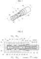
- FIG. 1 is a perspective view of the spool valve 1.
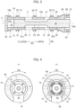
- FIG. 2 is a cross-sectional view of the spool valve 1, the view including an axis 2.
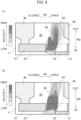
- FIG. 3 is an enlarged cross-sectional view around a groove section 23 of a spool 20 shown in FIG. 2 .
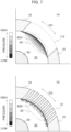
- FIG. 4 is a cross-sectional view of the spool valve 1, wherein (a) is a cross-sectional view along the line IVA-IVA in FIG. 2 , and (b) is a cross-sectional view along the line IVB-IVB in FIG. 2 .
- an extending direction of the axis 2 is referred to as an axial direction AD, and a circumferential direction and a radial direction around the axis 2 as the center are referred to as a circumferential direction CD and a radial direction RD, respectively.
- the axis 2 is a central axis of a sleeve 10 (described later) and a spool 20 (described later).
- a direction in which the spool 20 opens the outlet port 12 of the sleeve 10 (the right direction in FIG. 2 ) is called an opening direction
- a direction in which the spool 20 closes the outlet port 12 of the sleeve 10 is called a closing direction. Both the opening direction and the closing direction are parallel to the axial direction AD.
- the spool valve 1 As shown in FIG. 1 , the spool valve 1 according to the present embodiment has a substantially cylindrical outer shape extending in the axial direction AD.
- the spool valve 1 includes a sleeve 10, a spool (piston) 20, and a biasing device 30.
- the spool valve 1 As shown in FIG. 2 , for example, the spool valve 1 is inserted into a mounting hole 43 formed in a housing 40, and is attached to the housing 40.
- the sleeve 10 is a hollow cylindrical member extending in the axial direction AD.
- the spool 20 is movably housed in the housing hole 13 in the axial direction AD.
- the housing hole 13 is formed in the sleeve 10 and extends in the axial direction AD around the axis 2 as the center.
- An inlet port 11 and an outlet port 12 are provided on the outer peripheral surface 10a of the sleeve 10.
- the inlet port 11 is an inlet for the working fluid.
- the inlet port 11 connects with an inlet passage 41 formed in the housing 40.
- the inlet port 11 has a predetermined width in the axial direction AD and is formed over the entire circumferential direction CD except where the ribs 14 are provided.
- the inlet port 11 is always connected with a groove section 23 of the spool 20.
- the outlet port 12 is located between the inlet port 11 and a base end 20a of the spool 20.
- the outlet port 12 is an outlet for the working fluid.
- the outlet port 12 connects with an outlet passage 42 formed in the housing 40.
- the outlet port 12 is formed in regions 15 (see FIG. 5 ) arranged at intervals in the circumferential direction CD. Each region 15 defines the outer shape of the outlet port 12.
- the regions 15 are located at same intervals (e.g., every 90 degrees around the axis 2) along, for example, the circumferential CD.
- FIG. 5 is a plan view showing several examples of the outlet port 12 as viewed from the radial direction RD, wherein (a) shows a first example of the outlet port 12, (b) shows a second example of the outlet port 12, and (c) shows a third example of the outlet port 12.
- the outlet port 12 includes slits (slots, openings) 16.
- the slits 16 are arranged at intervals in the circumferential direction CD and extend in the axial direction AD in parallel with each other.
- the slits 16 are parallel to a plane which includes the axis 2 and extends in the radial direction RD (see FIG. 4(b) ).
- Two adjacent slits 16 and 16 are separated by a rib 19 between them.
- the respective widths of slits 16 and ribs 19 in the circumferential direction CD may be equal or different from each other.
- the widths of the slits 16 may be constant or different from each other. The same applies to the widths of the ribs 19.
- the outlet port 12 is sectioned into a first part (first segment) 17 and a second part (second segment) 18.
- the first part 17 is located closer to the inlet port 11 than the second part 18.
- the second part 18 is located farther from the inlet port 11 than the first part 17.
- the outer shape of the first part 17 has an isosceles triangle or a similar shape thereof with a vertex 17a facing the inlet port 11. That is, the width of the first part 17 along the circumferential CD increases as it approaches the second part 18.
- the rate of increase in the width along the circumferential CD may be constant as shown in FIG. 5(a) , or may increase according to an exponential function or a function with an increase rate similar to the exponential function as shown in FIG. 5(b) .
- the outer shape of the first part 17 is curved toward the first part 17 (i.e., toward the inside of the second part) on the two sides 17b and 17b forming the apex angle as compared with the triangular outer shape shown in FIG. 5(a) .
- the outer shape of the second part 18 is rectangular with sides extending in the axial direction AD and the circumferential direction CD, respectively. That is, the width of the first part 17 along the circumferential direction CD is constant.
- the region 15 of the outlet port 12 shown in FIG. 5 is enlarged outward from the region where the slits 16 are formed.
- the end of the axial AD of the slit 16 is located on the outline of the region 15 of the outlet port 12. That is, the outline of the region 15 of the outlet port 12 can be defined by connecting the ends of the axial AD of the adjacent slits 16.
- the shape of the region 15 is not limited to the substantially pentagonal shape described above. That is, according to the specification of the spool valve 1, the region 15 may be constituted only of the first part 17 or only of the second part 18.
- the outlet port 12 may be formed over the entire circumferential direction CD while having a predetermined width in the axial direction AD.
- the slits 16 are formed in the entire area of the circumferential direction CD at predetermined intervals in the circumferential direction CD.
- a through hole 50 is formed in the outer peripheral surface 10a of the sleeve 10.
- the through hole 50 extends in the radial direction RD and connects with a flow passage 47 formed in the housing 40.
- the through hole 50 also connects with the housing hole 13. Accordingly, the working fluid flows through the through hole 50 between the second land section 22 and the sleeve 10.
- the working fluid also flows through the same through hole (not shown) between the first land section 21 and the sleeve 10.
- the flow passage 47 is connected to the inlet passage 41 or a flow passage (not shown) connected to the inlet passage 41.
- the flow passage 47 is a flow passage in which cleanliness is maintained by a filter having a small pressure drop which is intentionally redundantly connected to the flow passage. Therefore, the pressure in the flow passage 47 is equal to the pressure in the inlet passage 41.
- the flow passage 47 may be connected to the outlet passage 42 or the flow passage (not shown) connected to the outlet passage 42. In this case, the fluid flowing through the flow passage 47 is relatively smaller in amount than the fluid flowing through the inlet passage 41 by the filter described above. Therefore, the pressure in the flow passage 47 is equal to the pressure in the outlet passage 42.
- protrusions 51 are provided on the outer peripheral surface 10a of the sleeve 10. Each protrusion 51 protrudes radially outward and is formed in an annular shape around the axis 2 as the center.
- the protrusion 51 has a groove 52 recessed inwardly in the radial direction RD.
- a seal member 53 such as an O-ring (see FIG. 2 ) is attached into the groove 52.
- the space (clearance) between the sleeve 10 and the housing 40 is partitioned, and leakage of the working fluid having flowed into the partitioned space can be prevented. Further, the position of the sleeve 10 in the mounting hole 43 is stably maintained by the pressure contact of the seal member 53.
- the tip end portion 10b of the sleeve 10 is provided with a washer (lid member) 55.
- the washer 55 is a disk covering the housing hole 13, and a pressure detecting port 56 is formed in the center thereof. As shown in FIG. 1 , the pressure detecting port 56 penetrates the washer 55 in the axial direction AD, and connects between the pressure detecting passage 45 and the housing hole 13.
- the washer 55 may be provided separately from the sleeve 10, or may be integrally formed with the sleeve 10 as a tip end surface of the sleeve 10 from a single base material.
- the pressure detecting passage 45 is connected to the inlet passage 41 or a flow passage (not shown) connected to the inlet passage 41. Therefore, the pressure in the pressure detecting passage 45 is equal to the pressure in the inlet passage 41.
- the spool 20 is a rod-shaped member having a circular cross section.
- the spool 20 extends in the axial direction AD from a base end 20a thereof to a tip end 20b thereof.
- the spool 20 is movably (reciprocatably) housed in the housing hole 13 in the axial direction AD, wherein the housing hole 13 is formed in the sleeve 10.
- the spool 20 includes a first land section (large-diameter portion) 21, a second land section (large-diameter portion) 22, and a groove section (small-diameter portion) 23.
- the first land section 21 and the second land section 22 are arranged in the axial direction AD with the groove section 23 between them.
- the first land section 21 and the second land section 22 have outer diameters substantially equal to (i.e., slightly smaller than) the inner diameter of the housing hole 13.
- the first land section 21 is located between the pressure detecting port 56 (washer 55) and the inlet port 11 in the axial direction AD.
- the second land section 22 is located at a position where the outlet port 12 can be closed by the movement of the sleeve 10.
- Grooves are formed on the outer peripheral surface 21a of the first land section 21 and the outer peripheral surface 22a of the second land section 22 to prevent the hydraulic fluid from sticking (Hydraulic Lock).
- the groove section 23 has a width in the axial direction AD that allows the connection between the inlet port 11 and the outlet port 12.
- the groove section 23 forms a flow passage of the working fluid in the groove section 23.
- the groove section 23 is recessed radially inward from the outer peripheral surface of the spool 20, and extends over the entire circumferential direction CD. Therefore, as viewed from the axial direction AD, the groove section 23 is formed in an annular shape centered on the axis 2.
- the inner surface of the groove section (small-diameter portion) 23 includes a cylindrical surface (intermediate part) 24, a first annular surface (expanded-diameter part) 25, and a second annular surface (expanded-diameter part) 26.
- the cylindrical surface 24 has a constant diameter and extends in the axial direction AD around the axis 2 as the center.
- the first annular surface 25 extends while curving from the cylindrical surface 24 toward the outer peripheral surface 21a of the first land section 21, and is connected to the outer peripheral surface 21a.
- the first annular surface 25 gradually deflects the flow of the working fluid, which has flowed into the groove section 23 from the inlet port 11, from the radial direction RD to the axial direction AD.
- the second annular surface 26 extends while curving from the cylindrical surface 24 toward the outer peripheral surface 22a of the second land section 22, and is connected to the outer peripheral surface 22a.
- the second annular surface 26 gradually deflects the flow of the working fluid, which will flow out from the groove section 23 to the outlet port 12, from the axial direction AD to the radial direction RD.
- the continuous deflection by each annular surface suppresses the excessive impact of the working fluid against the groove section 23 and reduces the excessive pressure on the spool 20 caused by the impact.
- the groove section 23 moves in the axial direction AD with the movement of the spool 20. Depending on the position of the groove section 23, a connection between the inlet port 11 and the outlet port is made through the groove section 23, or the connection between the inlet port and the outlet port 12 is terminated. The flow rate of the working fluid is adjusted by changing the opening area of the groove section 23 relative to the outlet port 12.
- the biasing device 30 biases the base end 20a of the spool 20 toward the tip end 20b (i.e., toward the closing direction of the valve).
- the biasing device 30 includes a spring 31 as a biasing member, a pair of retainers 32 and 32, and an operation part (handle) 33.
- the spring 31 presses the base end 20a of the spool 20 toward the tip end 20b of the spool.
- the spring 31 is a so-called compression coil spring and has a spring coefficient that produces a predetermined range of biasing forces.
- the spring 31 is held from both sides of the axial direction AD by the pair of retainers 32 and 32 and is housed in the operation part 33.
- the operation part 33 is a hollow and bottomed cylindrical member.
- the operation part 33 has a housing section 34 opening toward the spool 20.
- the housing section 34 houses the spring 31 and the pair of retainers 32 and 32.
- a screw thread 35 is formed on an outer peripheral surface 33a of the operation part 33.
- the screw thread 35 is screwed into a screw groove 44 formed on an inner peripheral surface 43a of the mounting hole 43. Accordingly, the operation part 33 moves in the axial direction AD by the rotation thereof about the axis 2.
- An annular groove 37 is formed in a part of the outer peripheral surface 33a of the operation part 33 between an edge portion 36 of the operation part 33 facing the spool 20 and the screw thread 35 (see FIG. 3 ).
- a seal member 53 is attached to the groove 37.
- the seal member 53 When the operation part 33 is inserted into the mounting hole 43, the seal member 53 is pressed toward the inner peripheral surface 43a of the mounting hole 43. The elastic deformation of the pressed seal member 53 prevents leakage of the working fluid from between the outer peripheral surface 33a of the operation part 33 and the inner peripheral surface 43a of the mounting hole 43.
- the housing section 34 of the operation part 33 connects with a drain flow passage 46.
- the drain flow passage 46 is connected to the outlet passage 42 or the flow passage (not shown) connected to the outlet passage 42, through an orifice (not shown). Accordingly, the pressure in the housing section 34 slowly changes to maintain equilibrium with the pressure in the outlet passage 42.
- a groove (notch) 38 may be formed at the edge portion 36 of the operation part 33. With the formation of the groove 38, even when the edge portion 36 of the operation part 33 comes into contact with the spool 20, communication between the drain flow passage 46 and the housing section 34 is maintained.
- the operation part 33 By rotating the operation part 33, the operation part 33 approaches the sleeve 10 or leaves from the sleeve 10.
- the spring 31 contracts, and the biasing force of the spring 31 and the pressure in the operation part 33 are transmitted to the spool 20 through the retainer 32. Accordingly, it is possible to adjust the pressure in the spool valve 1 by adjusting the rotation number of the operation part 33.
- the pressure can be set only by the mechanical operation which is only the rotation of the operation part 33. That is, the electric control using a solenoid or the like is unnecessary.
- the operation of the spool valve 1 according to the present embodiment as a pressure control valve or a flow control valve is basically the same as that of a conventional pressure control valve or a flow control valve equipped with a spool. That is, the position of the spool 20 is determined according to the difference between the pressure applied to the spool 20 by the biasing device 30 and the pressure of the working fluid in the pressure detecting port 56, and the opening area (opening degree) of the outlet port 12 is determined according to the position thus determined.
- the spool valve 1 When the flow rate of the working fluid flowing out from the outlet port 12 increases, the contraction of the spring 31 increases, and the biasing force in the flow rate also increases. The flow force due to the jet at the outlet port 12 also increases in accordance with the increase of the flow rate. Therefore, when the spool valve 1 is in the open state, the pressure of the working fluid increases as the flow rate increases (override property). However, when the spool valve 1 functions as a pressure control valve or a flow rate control valve, it is desirable for the spool valve 1 to be able to control the pressure of the working fluid at a constant level as the flow rate increases or decreases.
- the outlet port 12 is formed of the slits 16.
- the existence of these slits 16 disperses the jet of working fluid generated at the outlet port 12, decelerates the jet, and reduces the axial component of the flow.
- the flow force in the axial direction AD which acts to close the valve, is reduced, and thus the override property are improved.
- FIG. 6 is a diagram showing a numerical analysis result using Computational Fluid Dynamics (CFD) on the velocity distribution of a jet on a cross section including the axis 2.
- FIG. 6(a) shows a velocity distribution of a jet in a comparative example.
- FIG. 6(b) shows the velocity distribution of a jet in the present embodiment.
- the outlet port 12 of the present embodiment is constituted of the slits 16.
- the outlet port 112 of the comparative example is formed as a single opening. However, its outer shape is the same as that of the outlet port 12.
- the opening area of the outlet port in both analyses is set to the same value, which is half of the opening area when the outlet port is fully open.
- both figures show regions 65 at the same position surrounded by dotted lines.
- FIG. 6(b) shows a decrease of the velocity component contributing to the flow force in the axial direction AD among the velocity components of the jet 60.
- FIG. 7 is a diagram showing numerical analysis results using CFD of the static pressure distribution in the groove section 23 near the outlet port on the cross section orthogonal to the axis 2.
- FIG. 7(a) shows the static pressure distribution in the comparative example
- FIG. 7(b) shows the static pressure distribution in the present embodiment.
- the configuration of the comparative example shown in FIG. 7(a) is the same as that assumed in FIG. 6 (a) .
- the change in static pressure is indicated by the shade of color, and the darker the area (darker the black), the lower the static pressure.
- FIG. 7(b) shows an area (i.e., the darkest area) with the most significant pressure drop distributed near the boundary between the groove section 23 and the outlet port 12.
- FIG. 7(b) does not show the distribution of such region.
- a decrease in static pressure in a certain region means an increase in dynamic pressure in that region. That is, a decrease in static pressure indicates an acceleration of the working fluid in that region.
- the vicinity of the boundary between the groove section 23 and the outlet port 12 is the origin of the jet of the working fluid. Therefore, the reduction of the low-pressure region 62B shown in FIG. 7(b) indicates a decrease in the velocity of the jet 60 of the working fluid, that is, a decrease in the flow force.
- FIG. 8 is a graph showing a variation of the flow force with respect to the opening area of the outlet port.
- the white circle in the figure indicates the value obtained by the configuration of the comparative example described above, and the black circle in the figure indicates the value obtained by the configuration of the present embodiment. These values were obtained by numerical analysis using CFD.
- the flow force generated by the configuration of the present embodiment is lower than that generated by the configuration of the comparative example, regardless of the opening area of the outlet port. The percentage of this reduction increases as the opening area of the outlet port increases. For example, when the outlet port is fully open, the flow force is found to be reduced by about 50%.
- the flow force in the axial direction can be reduced compared to the case where the outlet port is composed of a single opening having the same opening area. That is, according to the present embodiment, the influence of the flow force on the override property of the pressure control valve or the flow control valve can be suppressed.
- the reduction of the flow force in the axial direction is obtained by constituting the outlet port with the slits. That is, in order to deflect the jet of the working fluid, it is not necessary to form a locally changed shape such as a recess on the inner surface of the groove section of the spool, as conventionally seen.
- a locally changed shape such as a recess on the inner surface of the groove section of the spool, as conventionally seen.
- the present embodiment does not require such a locally changed shape. Therefore, the original performance of the spool valve can be maintained for a long time even in an environment where foreign matter is likely to be mixed into the working fluid.
Landscapes
- Engineering & Computer Science (AREA)
- General Engineering & Computer Science (AREA)
- Mechanical Engineering (AREA)
- Physics & Mathematics (AREA)
- Fluid Mechanics (AREA)
- General Physics & Mathematics (AREA)
- Automation & Control Theory (AREA)
- Sliding Valves (AREA)
Abstract
Description
- The present disclosure relates to a spool valve.
- The spool valve has a sleeve and a spool housed in the sleeve. The spool valve is a valve that opens and closes a flow passage by moving the spool. The sleeve is provided with a housing hole for the spool. An inlet port and an outlet port for working fluid is provided on the side surface of the sleeve. The spool has a land section (a large-diameter portion) having an outer diameter approximately equal to the diameter of the housing hole of the sleeve, and a groove section (small-diameter portion) recessed radially inward from the outer peripheral surface of the land section. The groove section has a width capable of connecting between the inlet port and the outlet port. The opening degree of the spool valve is adjusted depending on the position of the groove section in accordance with the movement of the spool.
- When the spool valve is in an open state, the working fluid flows into the inlet port and is discharged from the outlet port through the groove section. Forces due to the flow of the working fluid act on the inner surface of the groove section near the inlet port and the outlet port. For example, when either the inlet port or the outlet port is throttled by the spool (in other words, if it is slightly open), a jet of the working fluid generated. If a pressure fluctuation caused by the jet breaks the balance between the aforementioned forces on an inlet port side and an outlet port side as described above, the spool generates forces in the axial and radial directions, respectively. These forces are generally referred to as flow forces (or fluid forces). Because the axial flow force acts in the direction of closing the valve, when the valve is open at a small opening degree, the working fluid tends to pulsate and the pressure control is likely to unstable. In this regard,
Patent Literature 1 discloses a spool type pressure control valve for suppressing this pulsation. - Patent Literature 1:
JP 2015-169212 A - It is desirable that the pressure control valve and the flow control valve can ideally control the pressure of the working fluid at a constant level with respect to an increase or decrease in the flow rate of the working fluid. However, these valves have a so-called override property in which the pressure of the working fluid increases with an increase in the flow rate of the working fluid. The above-mentioned flow forces also affect this override property. For example, when the flow force increases, the ratio of the pressure change of the working fluid to the flow change of the working fluid increases, and it becomes difficult to control the pressure or flow rate.
- An object of the present disclosure is to provide a spool valve capable of suppressing the influence of the flow force on the override property and being applied to a pressure control valve or a flow control valve.
- A spool valve according to an aspect of the present disclosure includes: a sleeve extending in an axial direction thereof, including an inlet port and an outlet port for working fluid; a spool movably housed in the sleeve in the axial direction; a biasing device including a biasing member configured to press a base end of the spool toward a tip end of the spool; and a pressure detecting port for the working fluid, opening toward the tip end of the spool; wherein the outlet port includes slits; the slits are arranged at intervals in a circumferential direction of the sleeve and extend in the axial direction.
- The outlet port may define an outer shape of the outlet port and may be formed in regions arranged at intervals in the circumferential direction. The outlet port may be sectioned into a first part and a second part located further from the inlet port than the first part, and a width of the first part of the sleeve along the circumferential direction may increase as it approaches the second part, and a width of the second part of the sleeve along the circumferential direction may be constant. The slits may be formed over the entire area in the circumferential direction at predetermined intervals in the circumferential direction.
- According to the present disclosure, it is possible to provide a spool valve capable of suppressing the influence of the flow force on the override property and being applied to a pressure control valve or a flow control valve.
-
-
FIG. 1 is a perspective view of a spool valve according to an embodiment of the present disclosure. -
FIG. 2 is a cross-sectional view of the spool valve, the view including an axis. -
FIG. 3 is an enlarged cross-sectional view around a groove section of the spool shown inFIG. 2 . -
FIG. 4 is a cross-sectional view of the spool valve, wherein (a) is a cross-sectional view along the line IVA-IVA inFIG. 2 , and (b) is a cross-sectional view along the line IVB-IVB inFIG. 2 . -
FIG. 5 is a plan view showing several examples of outlet ports as viewed from the radial direction, wherein (a) shows a first example of an outlet port, (b) shows a second example of an outlet port, and (c) shows a third example of an outlet port. -
FIG. 6 is a diagram showing numerical analysis results using Computational Fluid Dynamics (CFD) for the velocity distribution of a jet on a cross section including an axis, wherein (a) shows a velocity distribution of a jet in the comparative example, and (b) shows a velocity distribution of a jet in the present embodiment. -
FIG. 7 is a diagram showing numerical analysis results using CFD for the static pressure distribution in a groove section near an outlet port on a cross section orthogonal to an axis, wherein (a) shows the static pressure distribution in the comparative example, and (b) shows the static pressure distribution in the present embodiment. -
FIG. 8 is a graph showing a variation of the flow force with respect to the opening area of the outlet port. - Hereinafter, some embodiments of the present disclosure will be described. The same reference numerals will be used for common parts in each figure, and duplicate descriptions will be omitted. The spool valve according to the present embodiment can be applied as a pressure control valve or a flow control valve in an environment in which electric control is difficult, such as an aircraft fuel supply system, for example.
- A
spool valve 1 according to the present embodiment will be described below.FIG. 1 is a perspective view of thespool valve 1.FIG. 2 is a cross-sectional view of thespool valve 1, the view including anaxis 2.FIG. 3 is an enlarged cross-sectional view around agroove section 23 of aspool 20 shown inFIG. 2 .FIG. 4 is a cross-sectional view of thespool valve 1, wherein (a) is a cross-sectional view along the line IVA-IVA inFIG. 2 , and (b) is a cross-sectional view along the line IVB-IVB inFIG. 2 . - For convenience of explanation, an extending direction of the
axis 2 is referred to as an axial direction AD, and a circumferential direction and a radial direction around theaxis 2 as the center are referred to as a circumferential direction CD and a radial direction RD, respectively. Theaxis 2 is a central axis of a sleeve 10 (described later) and a spool 20 (described later). A direction in which thespool 20 opens theoutlet port 12 of the sleeve 10 (the right direction inFIG. 2 ) is called an opening direction, and a direction in which thespool 20 closes theoutlet port 12 of the sleeve 10 (the left direction inFIG. 2 ) is called a closing direction. Both the opening direction and the closing direction are parallel to the axial direction AD. - As shown in
FIG. 1 , thespool valve 1 according to the present embodiment has a substantially cylindrical outer shape extending in the axial direction AD. Thespool valve 1 includes asleeve 10, a spool (piston) 20, and abiasing device 30. As shown inFIG. 2 , for example, thespool valve 1 is inserted into amounting hole 43 formed in ahousing 40, and is attached to thehousing 40. - First, the
sleeve 10 will be described.
Thesleeve 10 is a hollow cylindrical member extending in the axial direction AD. Thespool 20 is movably housed in thehousing hole 13 in the axial direction AD. Thehousing hole 13 is formed in thesleeve 10 and extends in the axial direction AD around theaxis 2 as the center. - An
inlet port 11 and anoutlet port 12 are provided on the outerperipheral surface 10a of thesleeve 10. Theinlet port 11 is an inlet for the working fluid. Theinlet port 11 connects with aninlet passage 41 formed in thehousing 40. As shown inFIG. 4(a) , theinlet port 11 has a predetermined width in the axial direction AD and is formed over the entire circumferential direction CD except where theribs 14 are provided. Theinlet port 11 is always connected with agroove section 23 of thespool 20. - The
outlet port 12 is located between theinlet port 11 and abase end 20a of thespool 20. Theoutlet port 12 is an outlet for the working fluid. Theoutlet port 12 connects with anoutlet passage 42 formed in thehousing 40. As shown inFIG. 4(b) , theoutlet port 12 is formed in regions 15 (seeFIG. 5 ) arranged at intervals in the circumferential direction CD. Eachregion 15 defines the outer shape of theoutlet port 12. Theregions 15 are located at same intervals (e.g., every 90 degrees around the axis 2) along, for example, the circumferential CD. - The
outlet port 12 will be described in detail.
FIG. 5 is a plan view showing several examples of theoutlet port 12 as viewed from the radial direction RD, wherein (a) shows a first example of theoutlet port 12, (b) shows a second example of theoutlet port 12, and (c) shows a third example of theoutlet port 12. As shown in these figures, theoutlet port 12 includes slits (slots, openings) 16. Theslits 16 are arranged at intervals in the circumferential direction CD and extend in the axial direction AD in parallel with each other. Theslits 16 are parallel to a plane which includes theaxis 2 and extends in the radial direction RD (seeFIG. 4(b) ). Twoadjacent slits rib 19 between them. The respective widths ofslits 16 andribs 19 in the circumferential direction CD may be equal or different from each other. The widths of theslits 16 may be constant or different from each other. The same applies to the widths of theribs 19. - As shown in
FIG. 5 , theoutlet port 12 is sectioned into a first part (first segment) 17 and a second part (second segment) 18. Thefirst part 17 is located closer to theinlet port 11 than thesecond part 18. Thesecond part 18 is located farther from theinlet port 11 than thefirst part 17. - In the development planes of
FIG. 5 , the outer shape of thefirst part 17 has an isosceles triangle or a similar shape thereof with avertex 17a facing theinlet port 11. That is, the width of thefirst part 17 along the circumferential CD increases as it approaches thesecond part 18. The rate of increase in the width along the circumferential CD may be constant as shown inFIG. 5(a) , or may increase according to an exponential function or a function with an increase rate similar to the exponential function as shown inFIG. 5(b) . In the latter case, the outer shape of thefirst part 17 is curved toward the first part 17 (i.e., toward the inside of the second part) on the twosides FIG. 5(a) . - On the other hand, in the development planes shown in
FIG. 5 , the outer shape of thesecond part 18 is rectangular with sides extending in the axial direction AD and the circumferential direction CD, respectively. That is, the width of thefirst part 17 along the circumferential direction CD is constant. - For the sake of explanation, the
region 15 of theoutlet port 12 shown inFIG. 5 is enlarged outward from the region where theslits 16 are formed. However, in practice, the end of the axial AD of theslit 16 is located on the outline of theregion 15 of theoutlet port 12. That is, the outline of theregion 15 of theoutlet port 12 can be defined by connecting the ends of the axial AD of theadjacent slits 16. - The shape of the
region 15 is not limited to the substantially pentagonal shape described above. That is, according to the specification of thespool valve 1, theregion 15 may be constituted only of thefirst part 17 or only of thesecond part 18. - As shown in
FIG. 5(c) , theoutlet port 12 may be formed over the entire circumferential direction CD while having a predetermined width in the axial direction AD. In this case, theslits 16 are formed in the entire area of the circumferential direction CD at predetermined intervals in the circumferential direction CD. - A through
hole 50 is formed in the outerperipheral surface 10a of thesleeve 10. The throughhole 50 extends in the radial direction RD and connects with aflow passage 47 formed in thehousing 40. The throughhole 50 also connects with thehousing hole 13. Accordingly, the working fluid flows through the throughhole 50 between thesecond land section 22 and thesleeve 10. The working fluid also flows through the same through hole (not shown) between thefirst land section 21 and thesleeve 10. By allowing the working fluid to flow into these gaps, the fluid from theinlet passage 41 into the gaps is prevented, and thespool 20 is prevented from sticking due to the inflow of potential contaminants. - The
flow passage 47 is connected to theinlet passage 41 or a flow passage (not shown) connected to theinlet passage 41. Theflow passage 47 is a flow passage in which cleanliness is maintained by a filter having a small pressure drop which is intentionally redundantly connected to the flow passage. Therefore, the pressure in theflow passage 47 is equal to the pressure in theinlet passage 41. Theflow passage 47 may be connected to theoutlet passage 42 or the flow passage (not shown) connected to theoutlet passage 42. In this case, the fluid flowing through theflow passage 47 is relatively smaller in amount than the fluid flowing through theinlet passage 41 by the filter described above. Therefore, the pressure in theflow passage 47 is equal to the pressure in theoutlet passage 42. - As shown in
FIG. 3 ,protrusions 51 are provided on the outerperipheral surface 10a of thesleeve 10. Eachprotrusion 51 protrudes radially outward and is formed in an annular shape around theaxis 2 as the center. Theprotrusion 51 has agroove 52 recessed inwardly in the radial direction RD. Aseal member 53 such as an O-ring (seeFIG. 2 ) is attached into thegroove 52. When thespool valve 1 is inserted into the mountinghole 43, theseal member 53 is pressed against the innerperipheral surface 43a of the mountinghole 43 formed in thehousing 40 due to its elastic deformation. Thereby, the space (clearance) between thesleeve 10 and thehousing 40 is partitioned, and leakage of the working fluid having flowed into the partitioned space can be prevented. Further, the position of thesleeve 10 in the mountinghole 43 is stably maintained by the pressure contact of theseal member 53. - As shown in
FIG. 3 , thetip end portion 10b of thesleeve 10 is provided with a washer (lid member) 55. Thewasher 55 is a disk covering thehousing hole 13, and apressure detecting port 56 is formed in the center thereof. As shown inFIG. 1 , thepressure detecting port 56 penetrates thewasher 55 in the axial direction AD, and connects between thepressure detecting passage 45 and thehousing hole 13. Thewasher 55 may be provided separately from thesleeve 10, or may be integrally formed with thesleeve 10 as a tip end surface of thesleeve 10 from a single base material. Thepressure detecting passage 45 is connected to theinlet passage 41 or a flow passage (not shown) connected to theinlet passage 41. Therefore, the pressure in thepressure detecting passage 45 is equal to the pressure in theinlet passage 41. - Next, the
spool 20 will be described. - The
spool 20 is a rod-shaped member having a circular cross section. Thespool 20 extends in the axial direction AD from abase end 20a thereof to atip end 20b thereof. As shown inFIG. 1 , thespool 20 is movably (reciprocatably) housed in thehousing hole 13 in the axial direction AD, wherein thehousing hole 13 is formed in thesleeve 10. - The
spool 20 includes a first land section (large-diameter portion) 21, a second land section (large-diameter portion) 22, and a groove section (small-diameter portion) 23. Thefirst land section 21 and thesecond land section 22 are arranged in the axial direction AD with thegroove section 23 between them. Thefirst land section 21 and thesecond land section 22 have outer diameters substantially equal to (i.e., slightly smaller than) the inner diameter of thehousing hole 13. Thefirst land section 21 is located between the pressure detecting port 56 (washer 55) and theinlet port 11 in the axial direction AD. On the other hand, thesecond land section 22 is located at a position where theoutlet port 12 can be closed by the movement of thesleeve 10. Grooves (so-called labyrinth grooves) (not shown) are formed on the outerperipheral surface 21a of thefirst land section 21 and the outerperipheral surface 22a of thesecond land section 22 to prevent the hydraulic fluid from sticking (Hydraulic Lock). - The
groove section 23 has a width in the axial direction AD that allows the connection between theinlet port 11 and theoutlet port 12. Thegroove section 23 forms a flow passage of the working fluid in thegroove section 23. Thegroove section 23 is recessed radially inward from the outer peripheral surface of thespool 20, and extends over the entire circumferential direction CD. Therefore, as viewed from the axial direction AD, thegroove section 23 is formed in an annular shape centered on theaxis 2. - The inner surface of the groove section (small-diameter portion) 23 includes a cylindrical surface (intermediate part) 24, a first annular surface (expanded-diameter part) 25, and a second annular surface (expanded-diameter part) 26. The
cylindrical surface 24 has a constant diameter and extends in the axial direction AD around theaxis 2 as the center. - The first
annular surface 25 extends while curving from thecylindrical surface 24 toward the outerperipheral surface 21a of thefirst land section 21, and is connected to the outerperipheral surface 21a. The firstannular surface 25 gradually deflects the flow of the working fluid, which has flowed into thegroove section 23 from theinlet port 11, from the radial direction RD to the axial direction AD. - The second
annular surface 26 extends while curving from thecylindrical surface 24 toward the outerperipheral surface 22a of thesecond land section 22, and is connected to the outerperipheral surface 22a. The secondannular surface 26 gradually deflects the flow of the working fluid, which will flow out from thegroove section 23 to theoutlet port 12, from the axial direction AD to the radial direction RD. The continuous deflection by each annular surface suppresses the excessive impact of the working fluid against thegroove section 23 and reduces the excessive pressure on thespool 20 caused by the impact. - The
groove section 23 moves in the axial direction AD with the movement of thespool 20. Depending on the position of thegroove section 23, a connection between theinlet port 11 and the outlet port is made through thegroove section 23, or the connection between the inlet port and theoutlet port 12 is terminated. The flow rate of the working fluid is adjusted by changing the opening area of thegroove section 23 relative to theoutlet port 12. - Next, the biasing
device 30 will be described. - The biasing
device 30 biases thebase end 20a of thespool 20 toward thetip end 20b (i.e., toward the closing direction of the valve). As shown inFIG. 2 , the biasingdevice 30 includes aspring 31 as a biasing member, a pair ofretainers spring 31 presses thebase end 20a of thespool 20 toward thetip end 20b of the spool. Thespring 31 is a so-called compression coil spring and has a spring coefficient that produces a predetermined range of biasing forces. Thespring 31 is held from both sides of the axial direction AD by the pair ofretainers operation part 33. - The
operation part 33 is a hollow and bottomed cylindrical member. Theoperation part 33 has ahousing section 34 opening toward thespool 20. Thehousing section 34 houses thespring 31 and the pair ofretainers screw thread 35 is formed on an outerperipheral surface 33a of theoperation part 33. Thescrew thread 35 is screwed into ascrew groove 44 formed on an innerperipheral surface 43a of the mountinghole 43. Accordingly, theoperation part 33 moves in the axial direction AD by the rotation thereof about theaxis 2. Anannular groove 37 is formed in a part of the outerperipheral surface 33a of theoperation part 33 between anedge portion 36 of theoperation part 33 facing thespool 20 and the screw thread 35 (seeFIG. 3 ). Aseal member 53 is attached to thegroove 37. When theoperation part 33 is inserted into the mountinghole 43, theseal member 53 is pressed toward the innerperipheral surface 43a of the mountinghole 43. The elastic deformation of the pressedseal member 53 prevents leakage of the working fluid from between the outerperipheral surface 33a of theoperation part 33 and the innerperipheral surface 43a of the mountinghole 43. - Regardless of the position of the
operation part 33, thehousing section 34 of theoperation part 33 connects with adrain flow passage 46. Thedrain flow passage 46 is connected to theoutlet passage 42 or the flow passage (not shown) connected to theoutlet passage 42, through an orifice (not shown). Accordingly, the pressure in thehousing section 34 slowly changes to maintain equilibrium with the pressure in theoutlet passage 42. A groove (notch) 38 may be formed at theedge portion 36 of theoperation part 33. With the formation of thegroove 38, even when theedge portion 36 of theoperation part 33 comes into contact with thespool 20, communication between thedrain flow passage 46 and thehousing section 34 is maintained. - By rotating the
operation part 33, theoperation part 33 approaches thesleeve 10 or leaves from thesleeve 10. When theoperation part 33 is brought close to thesleeve 10, thespring 31 contracts, and the biasing force of thespring 31 and the pressure in theoperation part 33 are transmitted to thespool 20 through theretainer 32. Accordingly, it is possible to adjust the pressure in thespool valve 1 by adjusting the rotation number of theoperation part 33. In the present embodiment, the pressure can be set only by the mechanical operation which is only the rotation of theoperation part 33. That is, the electric control using a solenoid or the like is unnecessary. - Next, the operation of the
spool valve 1 will be described. The operation of thespool valve 1 according to the present embodiment as a pressure control valve or a flow control valve is basically the same as that of a conventional pressure control valve or a flow control valve equipped with a spool. That is, the position of thespool 20 is determined according to the difference between the pressure applied to thespool 20 by the biasingdevice 30 and the pressure of the working fluid in thepressure detecting port 56, and the opening area (opening degree) of theoutlet port 12 is determined according to the position thus determined. - When the flow rate of the working fluid flowing out from the
outlet port 12 increases, the contraction of thespring 31 increases, and the biasing force in the flow rate also increases. The flow force due to the jet at theoutlet port 12 also increases in accordance with the increase of the flow rate. Therefore, when thespool valve 1 is in the open state, the pressure of the working fluid increases as the flow rate increases (override property). However, when thespool valve 1 functions as a pressure control valve or a flow rate control valve, it is desirable for thespool valve 1 to be able to control the pressure of the working fluid at a constant level as the flow rate increases or decreases. - Therefore, in the present embodiment, the
outlet port 12 is formed of theslits 16. The existence of theseslits 16 disperses the jet of working fluid generated at theoutlet port 12, decelerates the jet, and reduces the axial component of the flow. As a result, the flow force in the axial direction AD, which acts to close the valve, is reduced, and thus the override property are improved. -
FIG. 6 is a diagram showing a numerical analysis result using Computational Fluid Dynamics (CFD) on the velocity distribution of a jet on a cross section including theaxis 2.FIG. 6(a) shows a velocity distribution of a jet in a comparative example.FIG. 6(b) shows the velocity distribution of a jet in the present embodiment. As described above, theoutlet port 12 of the present embodiment is constituted of theslits 16. On the other hand, theoutlet port 112 of the comparative example is formed as a single opening. However, its outer shape is the same as that of theoutlet port 12. In addition, the opening area of the outlet port in both analyses is set to the same value, which is half of the opening area when the outlet port is fully open. - As shown in
FIGs. 6(a) and 6(b) , thejet 60 of the working fluid flows generally outward in the radial direction in both analysis results, but thejet 60 is slightly inclined toward the opening direction of the spool valve 1 (to the right in the figures). However, the inclination of thejet 60 toward the opening direction shown inFIG. 6(b) is smaller than the inclination of thejet 60 toward the opening direction shown inFIG. 6(a) . Further, both figures showregions 65 at the same position surrounded by dotted lines. When comparing the velocity distributions in theseregions 65, inFIG. 6(a) , a flow with a relatively large velocity occurs over a wide area, while inFIG. 6(b) , a flow with a similar velocity decreases and its distribution shrinks. - The velocity component of the
jet 60 toward the opening direction of thespool valve 1 contributes to the flow force in the axial direction AD acting in the closing direction of thespool valve 1. Therefore,FIG. 6(b) shows a decrease of the velocity component contributing to the flow force in the axial direction AD among the velocity components of thejet 60. -
FIG. 7 is a diagram showing numerical analysis results using CFD of the static pressure distribution in thegroove section 23 near the outlet port on the cross section orthogonal to theaxis 2.FIG. 7(a) shows the static pressure distribution in the comparative example, andFIG. 7(b) shows the static pressure distribution in the present embodiment. The configuration of the comparative example shown inFIG. 7(a) is the same as that assumed inFIG. 6 (a) . In both figures, the change in static pressure is indicated by the shade of color, and the darker the area (darker the black), the lower the static pressure. - Focusing on the
region 63 surrounded by the two-dot chain line, it can be seen that the low-pressure region 62B shown inFIG. 7(b) is smaller than the low-pressure region 62A shown inFIG. 7(a) . In addition,FIG. 7(a) shows an area (i.e., the darkest area) with the most significant pressure drop distributed near the boundary between thegroove section 23 and theoutlet port 12. On the other hand,FIG. 7(b) does not show the distribution of such region. - A decrease in static pressure in a certain region means an increase in dynamic pressure in that region. That is, a decrease in static pressure indicates an acceleration of the working fluid in that region. On the other hand, as shown in
FIG. 6 , the vicinity of the boundary between thegroove section 23 and theoutlet port 12 is the origin of the jet of the working fluid. Therefore, the reduction of the low-pressure region 62B shown inFIG. 7(b) indicates a decrease in the velocity of thejet 60 of the working fluid, that is, a decrease in the flow force. -
FIG. 8 is a graph showing a variation of the flow force with respect to the opening area of the outlet port. The white circle in the figure indicates the value obtained by the configuration of the comparative example described above, and the black circle in the figure indicates the value obtained by the configuration of the present embodiment. These values were obtained by numerical analysis using CFD. As shown inFIG. 8 , the flow force generated by the configuration of the present embodiment is lower than that generated by the configuration of the comparative example, regardless of the opening area of the outlet port. The percentage of this reduction increases as the opening area of the outlet port increases. For example, when the outlet port is fully open, the flow force is found to be reduced by about 50%. - Thus, according to the present embodiment, the flow force in the axial direction can be reduced compared to the case where the outlet port is composed of a single opening having the same opening area. That is, according to the present embodiment, the influence of the flow force on the override property of the pressure control valve or the flow control valve can be suppressed.
- The reduction of the flow force in the axial direction is obtained by constituting the outlet port with the slits. That is, in order to deflect the jet of the working fluid, it is not necessary to form a locally changed shape such as a recess on the inner surface of the groove section of the spool, as conventionally seen. When the surface facing the working fluid is provided with a part such as a small recess, the foreign matter in the working fluid tends to adhere to the part. The adhesion of the foreign matter disturbs the deflection of the jet. However, the present embodiment does not require such a locally changed shape. Therefore, the original performance of the spool valve can be maintained for a long time even in an environment where foreign matter is likely to be mixed into the working fluid.
- It should be noted that the present disclosure is not limited to the embodiments described above, is shown by the description of the claims, and further includes all modifications within the meaning and scope of the same as the description of the claims.
Claims (4)
- A spool valve comprising:a sleeve extending in an axial direction thereof, including an inlet port and an outlet port for working fluid;a spool movably housed in the sleeve in the axial direction;a biasing device including a biasing member configured to press a base end of the spool toward a tip end of the spool; anda pressure detecting port for the working fluid, opening toward the tip end of the spool; whereinthe outlet port includes slits;the slits are arranged at intervals in a circumferential direction of the sleeve and extend in the axial direction.
- The spool valve according to claim 1, wherein
the outlet port defines an outer shape of the outlet port and is formed in regions arranged at intervals in the circumferential direction. - The spool valve according to claim 2, whereinthe outlet port is sectioned into a first part and a second part located further from the inlet port than the first part, anda width of the first part of the sleeve along the circumferential direction increases as it approaches the second part, anda width of the second part of the sleeve along the circumferential direction is constant.
- The spool valve according to claim 1, wherein
the slits are formed over the entire area in the circumferential direction at predetermined intervals in the circumferential direction.
Applications Claiming Priority (2)
| Application Number | Priority Date | Filing Date | Title |
|---|---|---|---|
| JP2021152171 | 2021-09-17 | ||
| PCT/JP2022/033990 WO2023042775A1 (en) | 2021-09-17 | 2022-09-12 | Spool valve |
Publications (2)
| Publication Number | Publication Date |
|---|---|
| EP4390189A1 true EP4390189A1 (en) | 2024-06-26 |
| EP4390189A4 EP4390189A4 (en) | 2025-08-06 |
Family
ID=85602862
Family Applications (1)
| Application Number | Title | Priority Date | Filing Date |
|---|---|---|---|
| EP22869922.9A Pending EP4390189A4 (en) | 2021-09-17 | 2022-09-12 | Slide valve |
Country Status (4)
| Country | Link |
|---|---|
| US (1) | US12474724B2 (en) |
| EP (1) | EP4390189A4 (en) |
| JP (1) | JP7687417B2 (en) |
| WO (1) | WO2023042775A1 (en) |
Family Cites Families (14)
| Publication number | Priority date | Publication date | Assignee | Title |
|---|---|---|---|---|
| GB838839A (en) * | 1957-10-15 | 1960-06-22 | Cincinnati Milling Machine Co | Method of manufacturing bushing type spool valves |
| JPS5652454Y2 (en) * | 1974-05-31 | 1981-12-07 | ||
| DE2949231C2 (en) * | 1979-12-07 | 1984-12-13 | Mannesmann Rexroth GmbH, 8770 Lohr | Pressure medium valve, in particular pressure reducing valve |
| EP0076664A1 (en) * | 1981-10-02 | 1983-04-13 | J.H. Fenner & Co. Limited | Improvements in or relating to control of pneumatic motors |
| US5004015A (en) * | 1984-03-01 | 1991-04-02 | Mannesmann Rexroth Gmbh | Directional control device |
| JPS61256082A (en) * | 1985-05-07 | 1986-11-13 | Hisaka Works Ltd | Valve with fluid buffering part |
| JPH0641025Y2 (en) * | 1989-05-25 | 1994-10-26 | 豊田工機株式会社 | Valve device |
| JP2007315605A (en) * | 2002-09-30 | 2007-12-06 | Jtekt Corp | solenoid valve |
| US8578967B2 (en) * | 2009-01-29 | 2013-11-12 | Pratt & Whitney Canada Corp. | Pressure regulating valve for aircraft engine |
| JP5921967B2 (en) | 2012-06-13 | 2016-05-24 | 東レ株式会社 | Resin composite molded body and method for producing resin composite molded body |
| JP2015169212A (en) | 2014-03-04 | 2015-09-28 | 株式会社デンソー | Fluid control valve |
| US10711903B2 (en) * | 2017-06-08 | 2020-07-14 | Hamilton Sundstrand Corporation | Transfer valves |
| US11242041B2 (en) * | 2018-04-23 | 2022-02-08 | Safran Landing Systems Canada Inc. | Slow response solenoid hydraulic valve, and associated systems and methods |
| US11085545B2 (en) * | 2018-09-26 | 2021-08-10 | National Coupling Company, Inc. | Pilot-actuated spool valve having rod retainer |
-
2022
- 2022-09-12 JP JP2023548451A patent/JP7687417B2/en active Active
- 2022-09-12 WO PCT/JP2022/033990 patent/WO2023042775A1/en not_active Ceased
- 2022-09-12 EP EP22869922.9A patent/EP4390189A4/en active Pending
-
2024
- 2024-01-04 US US18/404,065 patent/US12474724B2/en active Active
Also Published As
| Publication number | Publication date |
|---|---|
| JPWO2023042775A1 (en) | 2023-03-23 |
| US20240143001A1 (en) | 2024-05-02 |
| EP4390189A4 (en) | 2025-08-06 |
| US12474724B2 (en) | 2025-11-18 |
| WO2023042775A1 (en) | 2023-03-23 |
| JP7687417B2 (en) | 2025-06-03 |
Similar Documents
| Publication | Publication Date | Title |
|---|---|---|
| US11249497B2 (en) | Balanced trim regulator | |
| US4679765A (en) | Low leakage orifice-controlled poppet valve | |
| EP2898386B1 (en) | Balanced regulator with inlet pressure sensing tube | |
| EP3026313A1 (en) | Control valve | |
| JP5966094B2 (en) | Solenoid valve | |
| KR102057659B1 (en) | Flow regulator unit | |
| EP3026312B1 (en) | Control valve | |
| KR101699571B1 (en) | Pressure control valve | |
| CS270418B2 (en) | Pressure limiting valve for hydraulic outfit of face | |
| CN101384847A (en) | Pilot operated pressure limiting valve | |
| CN109578645A (en) | Adjuster with convertible trim assemblies | |
| US3845782A (en) | Flow control valve for hydraulic damper and the like | |
| US12474724B2 (en) | Spool valve | |
| US9678516B2 (en) | Balanced regulator having a balanced trim including a variable pressure sense area | |
| EP4394221A1 (en) | Spool valve | |
| EP3362866B1 (en) | Balanced regulator with targeted boost sensing tube | |
| US10774894B2 (en) | Hydraulic damping valve | |
| US5495869A (en) | Changeover valve and flow control valve assembly having the same | |
| KR102641641B1 (en) | check valve | |
| US11971114B1 (en) | Solenoid adapter | |
| EP3561347A1 (en) | Passive valve | |
| EP3284931B1 (en) | Pressure regulating valve with flow anti-rotation | |
| KR102502817B1 (en) | Pressure reducing valve | |
| EP1371831A1 (en) | Exhaust pressure control valve | |
| CN114041022B (en) | Coolant valve for motor vehicles |
Legal Events
| Date | Code | Title | Description |
|---|---|---|---|
| STAA | Information on the status of an ep patent application or granted ep patent |
Free format text: STATUS: THE INTERNATIONAL PUBLICATION HAS BEEN MADE |
|
| PUAI | Public reference made under article 153(3) epc to a published international application that has entered the european phase |
Free format text: ORIGINAL CODE: 0009012 |
|
| STAA | Information on the status of an ep patent application or granted ep patent |
Free format text: STATUS: REQUEST FOR EXAMINATION WAS MADE |
|
| 17P | Request for examination filed |
Effective date: 20240323 |
|
| AK | Designated contracting states |
Kind code of ref document: A1 Designated state(s): AL AT BE BG CH CY CZ DE DK EE ES FI FR GB GR HR HU IE IS IT LI LT LU LV MC MK MT NL NO PL PT RO RS SE SI SK SM TR |
|
| DAV | Request for validation of the european patent (deleted) | ||
| DAX | Request for extension of the european patent (deleted) | ||
| A4 | Supplementary search report drawn up and despatched |
Effective date: 20250707 |
|
| RIC1 | Information provided on ipc code assigned before grant |
Ipc: F16K 3/32 20060101AFI20250701BHEP Ipc: F16K 3/24 20060101ALI20250701BHEP Ipc: F16K 3/34 20060101ALI20250701BHEP Ipc: F16K 11/07 20060101ALI20250701BHEP Ipc: F16K 47/08 20060101ALI20250701BHEP Ipc: F16K 27/04 20060101ALI20250701BHEP |