EP4390168A1 - Sensor holder and vehicle-wheel bearing device - Google Patents
Sensor holder and vehicle-wheel bearing device Download PDFInfo
- Publication number
- EP4390168A1 EP4390168A1 EP22858301.9A EP22858301A EP4390168A1 EP 4390168 A1 EP4390168 A1 EP 4390168A1 EP 22858301 A EP22858301 A EP 22858301A EP 4390168 A1 EP4390168 A1 EP 4390168A1
- Authority
- EP
- European Patent Office
- Prior art keywords
- sensor
- axial direction
- support part
- nut
- sensor support
- Prior art date
- Legal status (The legal status is an assumption and is not a legal conclusion. Google has not performed a legal analysis and makes no representation as to the accuracy of the status listed.)
- Pending
Links
Images



Classifications
-
- F—MECHANICAL ENGINEERING; LIGHTING; HEATING; WEAPONS; BLASTING
- F16—ENGINEERING ELEMENTS AND UNITS; GENERAL MEASURES FOR PRODUCING AND MAINTAINING EFFECTIVE FUNCTIONING OF MACHINES OR INSTALLATIONS; THERMAL INSULATION IN GENERAL
- F16C—SHAFTS; FLEXIBLE SHAFTS; ELEMENTS OR CRANKSHAFT MECHANISMS; ROTARY BODIES OTHER THAN GEARING ELEMENTS; BEARINGS
- F16C41/00—Other accessories, e.g. devices integrated in the bearing not relating to the bearing function as such
-
- B—PERFORMING OPERATIONS; TRANSPORTING
- B60—VEHICLES IN GENERAL
- B60B—VEHICLE WHEELS; CASTORS; AXLES FOR WHEELS OR CASTORS; INCREASING WHEEL ADHESION
- B60B27/00—Hubs
- B60B27/0005—Hubs with ball bearings
-
- B—PERFORMING OPERATIONS; TRANSPORTING
- B60—VEHICLES IN GENERAL
- B60B—VEHICLE WHEELS; CASTORS; AXLES FOR WHEELS OR CASTORS; INCREASING WHEEL ADHESION
- B60B27/00—Hubs
- B60B27/0047—Hubs characterised by functional integration of other elements
- B60B27/0068—Hubs characterised by functional integration of other elements the element being a sensor
-
- B—PERFORMING OPERATIONS; TRANSPORTING
- B60—VEHICLES IN GENERAL
- B60B—VEHICLE WHEELS; CASTORS; AXLES FOR WHEELS OR CASTORS; INCREASING WHEEL ADHESION
- B60B27/00—Hubs
- B60B27/0094—Hubs one or more of the bearing races are formed by the hub
-
- F—MECHANICAL ENGINEERING; LIGHTING; HEATING; WEAPONS; BLASTING
- F16—ENGINEERING ELEMENTS AND UNITS; GENERAL MEASURES FOR PRODUCING AND MAINTAINING EFFECTIVE FUNCTIONING OF MACHINES OR INSTALLATIONS; THERMAL INSULATION IN GENERAL
- F16C—SHAFTS; FLEXIBLE SHAFTS; ELEMENTS OR CRANKSHAFT MECHANISMS; ROTARY BODIES OTHER THAN GEARING ELEMENTS; BEARINGS
- F16C19/00—Bearings with rolling contact, for exclusively rotary movement
- F16C19/02—Bearings with rolling contact, for exclusively rotary movement with bearing balls essentially of the same size in one or more circular rows
- F16C19/14—Bearings with rolling contact, for exclusively rotary movement with bearing balls essentially of the same size in one or more circular rows for both radial and axial load
- F16C19/18—Bearings with rolling contact, for exclusively rotary movement with bearing balls essentially of the same size in one or more circular rows for both radial and axial load with two or more rows of balls
- F16C19/181—Bearings with rolling contact, for exclusively rotary movement with bearing balls essentially of the same size in one or more circular rows for both radial and axial load with two or more rows of balls with angular contact
- F16C19/183—Bearings with rolling contact, for exclusively rotary movement with bearing balls essentially of the same size in one or more circular rows for both radial and axial load with two or more rows of balls with angular contact with two rows at opposite angles
- F16C19/184—Bearings with rolling contact, for exclusively rotary movement with bearing balls essentially of the same size in one or more circular rows for both radial and axial load with two or more rows of balls with angular contact with two rows at opposite angles in O-arrangement
- F16C19/186—Bearings with rolling contact, for exclusively rotary movement with bearing balls essentially of the same size in one or more circular rows for both radial and axial load with two or more rows of balls with angular contact with two rows at opposite angles in O-arrangement with three raceways provided integrally on parts other than race rings, e.g. third generation hubs
-
- F—MECHANICAL ENGINEERING; LIGHTING; HEATING; WEAPONS; BLASTING
- F16—ENGINEERING ELEMENTS AND UNITS; GENERAL MEASURES FOR PRODUCING AND MAINTAINING EFFECTIVE FUNCTIONING OF MACHINES OR INSTALLATIONS; THERMAL INSULATION IN GENERAL
- F16C—SHAFTS; FLEXIBLE SHAFTS; ELEMENTS OR CRANKSHAFT MECHANISMS; ROTARY BODIES OTHER THAN GEARING ELEMENTS; BEARINGS
- F16C33/00—Parts of bearings; Special methods for making bearings or parts thereof
- F16C33/72—Sealings
- F16C33/723—Shaft end sealing means, e.g. cup-shaped caps or covers
-
- F—MECHANICAL ENGINEERING; LIGHTING; HEATING; WEAPONS; BLASTING
- F16—ENGINEERING ELEMENTS AND UNITS; GENERAL MEASURES FOR PRODUCING AND MAINTAINING EFFECTIVE FUNCTIONING OF MACHINES OR INSTALLATIONS; THERMAL INSULATION IN GENERAL
- F16C—SHAFTS; FLEXIBLE SHAFTS; ELEMENTS OR CRANKSHAFT MECHANISMS; ROTARY BODIES OTHER THAN GEARING ELEMENTS; BEARINGS
- F16C33/00—Parts of bearings; Special methods for making bearings or parts thereof
- F16C33/72—Sealings
- F16C33/76—Sealings of ball or roller bearings
- F16C33/78—Sealings of ball or roller bearings with a diaphragm, disc, or ring, with or without resilient members
- F16C33/7816—Details of the sealing or parts thereof, e.g. geometry, material
- F16C33/783—Details of the sealing or parts thereof, e.g. geometry, material of the mounting region
-
- F—MECHANICAL ENGINEERING; LIGHTING; HEATING; WEAPONS; BLASTING
- F16—ENGINEERING ELEMENTS AND UNITS; GENERAL MEASURES FOR PRODUCING AND MAINTAINING EFFECTIVE FUNCTIONING OF MACHINES OR INSTALLATIONS; THERMAL INSULATION IN GENERAL
- F16C—SHAFTS; FLEXIBLE SHAFTS; ELEMENTS OR CRANKSHAFT MECHANISMS; ROTARY BODIES OTHER THAN GEARING ELEMENTS; BEARINGS
- F16C41/00—Other accessories, e.g. devices integrated in the bearing not relating to the bearing function as such
- F16C41/007—Encoders, e.g. parts with a plurality of alternating magnetic poles
-
- F—MECHANICAL ENGINEERING; LIGHTING; HEATING; WEAPONS; BLASTING
- F16—ENGINEERING ELEMENTS AND UNITS; GENERAL MEASURES FOR PRODUCING AND MAINTAINING EFFECTIVE FUNCTIONING OF MACHINES OR INSTALLATIONS; THERMAL INSULATION IN GENERAL
- F16C—SHAFTS; FLEXIBLE SHAFTS; ELEMENTS OR CRANKSHAFT MECHANISMS; ROTARY BODIES OTHER THAN GEARING ELEMENTS; BEARINGS
- F16C2326/00—Articles relating to transporting
- F16C2326/01—Parts of vehicles in general
- F16C2326/02—Wheel hubs or castors
Definitions
- the present invention relates to a sensor holder and a bearing device for vehicle wheel.
- a small-diameter stepped portion 3a of which diameter is smaller than that of the outer-side end of the hub ring 3 is formed.
- a vehicle wheel mounting flange 3b for mounting a vehicle wheel is integrally formed.
- a plurality of bolt holes 3f is formed in the vehicle wheel mounting flange 3b.
- a hub bolt 3e for fastening the hub ring 3 to the vehicle wheel or a brake part is press-fitted in the bolt hole 3f.
- the sensor holder 12 is formed of, for example, a resin member.
- the sensor holder 12 may be an injection-molded product or a machined product.
- the sensor support part 122 protrudes from the bottom surface portion 121b of the cap part 121 toward one side in the axial direction, and supports the rotation speed sensor 13.
- the sensor support part 122 is disposed on the bottom surface portion 121b at a location facing the magnetic encoder 11.
- the sensor support part 122 of the sensor holder 12 attached to the bearing device for a vehicle wheel 1 is located at an upper end of the bottom surface portion 121b.
Landscapes
- Engineering & Computer Science (AREA)
- General Engineering & Computer Science (AREA)
- Mechanical Engineering (AREA)
- Rolling Contact Bearings (AREA)
- Sealing Of Bearings (AREA)
Abstract
Description
- The present invention relates to a sensor holder and a bearing device for vehicle wheel.
- Conventionally, a bearing device for vehicle wheel that rotatably supports a wheel in a suspension device of an automobile or the like is known. There is a bearing device for vehicle wheel in which a rotational speed detection device that detects a rotational speed of a wheel is added to control an antilock brake system (ABS).
- For example, in a bearing device for vehicle wheel disclosed in Patent Literature 1, an encoder is supported at an axial end of an inner member, and a sensor holder that supports a sensor for detecting displacement of the encoder is attached to an axial end of an outer member.
- The sensor holder includes a cap part fitted to the axial end of the outer member, a sensor support part protruding from a cap part toward one side in the axial direction and supporting the sensor for detecting displacement of the encoder, and a nut holding part protruding from the cap part toward one side in the axial direction and holding a nut for fixing the sensor to the cap part. A mounting flange is fixed to the sensor, and the sensor is fixed to the cap part by fastening the mounting flange to the nut with a bolt in a state where the sensor is fitted to the sensor support part.
- The sensor support part and the nut holding part protrude at the same height in the axial direction, and the mounting flange is in contact with both the sensor support part and the nut holding part in a state where the sensor is fixed to the cap part.
- Patent Literature 1:
JP-A-2016-148422 - As described above, since a sensor support part and a nut holding part protrude at the same height and are both in contact with a mounting flange, when the sensor support part is warped or a sensor holder has been deformed when being attached to an outer member, a sensor in contact with the sensor support part may be tilted to affect the performance of the sensor to read an encoder.
- The present invention has been made in view of the above situation, and provides a sensor holder and a bearing device for vehicle wheel that can prevent an effect on a performance of a sensor to read an encoder caused by a warp of a sensor support part, deformation of the sensor holder, or the like.
- That is, a sensor holder is attached to an end portion, in an axial direction, of an outer member that is located on an outer diameter side of an inner member supporting an encoder at an end portion in the axial direction, and rotatably supports the inner member via a double row of rolling elements, the sensor holder including a cap part fitted to the outer member so as to close an opening on one end side in the axial direction of the outer member, a sensor support part that protrudes from the cap part toward one side in the axial direction at a location on the cap part facing the encoder and supports a sensor that detects displacement of the encoder, and a nut holding part that protrudes from the cap part toward one side in the axial direction and holds a nut for fixing the sensor to the cap part. The sensor support part and the nut holding part are formed to be separated from each other, and an end surface on one side in the axial direction of the nut held by the nut holding part protrudes toward one side in the axial direction further than an end surface on one side in the axial direction of the sensor support part.
- According to the present invention, an effect on a performance of a sensor to read an encoder can be prevented.
-
-
FIG. 1 is a side sectional view illustrating a bearing device for vehicle wheel. -
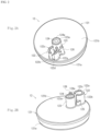
FIG. 2A is an upper perspective view illustrating a sensor holder, andFIG. 2B is a lower perspective view illustrating the sensor holder. -
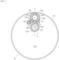
FIG. 3 is a view illustrating a sensor holder viewed along an axial direction from an inner-side. -
FIG. 4 is a side sectional view illustrating the sensor holder. -
FIG. 5 is a partially enlarged side sectional view illustrating a sensor holder to which a rotation speed sensor is attached. -
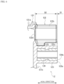
FIG. 6 is a partially enlarged side sectional view illustrating the sensor holder. - Hereinafter, a mode for carrying out the present invention will be described with reference to the accompanying drawings.
- A bearing device for a vehicle wheel 1 illustrated in
FIG. 1 is one embodiment of a bearing device for vehicle wheel including a sensor holder according to the present invention, and rotatably supports a wheel in a suspension device of a vehicle such as an automobile. - The bearing device for a vehicle wheel 1 has a configuration called a third generation, and includes an outer ring 2 that is an outer member, a
hub ring 3 and an inner ring 4 that are inner members, two roller rows of an inner-side ball row 5 and an outer-side ball row 6, amagnetic encoder 11, and asensor holder 12. - In the following description, the term, axial direction, represents a direction along a rotation axis X of the bearing device for a vehicle wheel 1. Furthermore, the term, inner-side, represents one side in the axial direction which is closer to a vehicle body when the bearing device for a vehicle wheel 1 is attached to the vehicle body, and the term, outer-side, represents the other side in the axial direction which is closer to the wheel when the bearing device for a vehicle wheel 1 is attached to the vehicle body.
- On an inner-side end of the outer ring 2, an inner-
side opening 2a to which thesensor holder 12 can be fitted is formed. On an outer-side end of the outer ring 2, an outer-side opening 2b to which an outer-side sealing member 9 can be fitted is formed. Thesensor holder 12 is fitted to the inner-side opening 2a that opens at one end side in the axial direction of an annular space S formed by the outer ring 2 and thehub ring 3, and the outer-side sealing member 9 is fitted to the outer-side opening 2b that is an opening on the other end side in the axial direction of the annular space S, whereby the annular space S, which is the inside of the bearing is sealed. - On the inner circumferential surface of the outer ring 2, an
outer raceway surface 2c on the inner-side and anouter raceway surface 2d on the outer-side are formed. On the outer circumferential surface of the outer ring 2, a vehiclebody mounting flange 2e for mounting the outer ring 2 to a vehicle body member is integrally formed. The vehiclebody mounting flange 2e is provided with abolt hole 2g into which a fastening member (a bolt in the embodiment) for fastening together the vehicle body member and the outer ring 2 is inserted. The outer ring 2 is located on the outer diameter side of thehub ring 3 and the inner ring 4. - On the outer circumferential surface of an inner-side end of the
hub ring 3, a small-diameterstepped portion 3a of which diameter is smaller than that of the outer-side end of thehub ring 3 is formed. On an outer-side end of thehub ring 3, a vehiclewheel mounting flange 3b for mounting a vehicle wheel is integrally formed. A plurality ofbolt holes 3f is formed in the vehiclewheel mounting flange 3b. Ahub bolt 3e for fastening thehub ring 3 to the vehicle wheel or a brake part is press-fitted in thebolt hole 3f. - On the outer circumferential surface of the
hub ring 3, an inner raceway surface 3c is provided on the outer-side so as to face theouter raceway surface 2d on the outer-side of the outer ring 2. That is, on the outer-side of the inner member, thehub ring 3 forms the inner raceway surface 3c. Aseal land portion 3d for the outer-side sealingmember 9 is formed on a proximal side of the vehiclewheel mounting flange 3b of thehub ring 3. - The outer-
side sealing member 9 includes acore metal 91 fitted in the outer-side opening 2b of the outer ring 2, and aseal member 92 integrally joined to thecore metal 91. Ametal ring 35 is fitted in theseal land portion 3d of thehub ring 3. Aside lip 92a of theseal member 92 is in sliding contact with themetal ring 35. That is, theside lip 92a of theseal member 92 is in sliding contact with theseal land portion 3d of thehub ring 3 via themetal ring 35. - The bearing device for a vehicle wheel 1 however may be configured to have no
metal ring 35 so that theside lip 92a of theseal member 92 is in direct sliding contact with theseal land portion 3d of thehub ring 3. Agrease lip 92b of theseal member 92 is in direct sliding contact with theseal land portion 3d of thehub ring 3. - The inner ring 4 is provided on the small-diameter
stepped portion 3a of thehub ring 3. The inner ring 4 is fixed to the small-diameterstepped portion 3a of thehub ring 3 by press fitting and swaging. The inner ring 4 applies a preload to the inner-side ball row 5 and the outer-side ball row 6 which are roller rows. The inner ring 4 has an inner-side end surface 4b at an inner-side end. Aswaged portion 3h is formed at the inner-side end of thehub ring 3 by swaging to be in contact with the inner-side end surface 4b of the inner ring 4. - On the outer circumferential surface of the inner ring 4, an inner raceway surface 4a is provided on the inner-side so as to face the
outer raceway surface 2c on the inner-side of the outer ring 2. That is, on the inner-side of the inner member, the inner ring 4 forms the inner raceway surface 4a. - The inner-side ball row 5 and the outer-
side ball row 6, which are roller rows, are configured that a plurality of balls 7, or rolling elements, is held by a cage 8. The inner-side ball row 5 is held between the inner raceway surface 4a of the inner ring 4 and theouter raceway surface 2c on the inner-side of the outer ring 2 so as to roll. The outer-side ball row 6 is held between the inner raceway surface 3c of thehub ring 3 and theouter raceway surface 2d on the outer-side of the outer ring 2 so as to roll. That is, the inner-side ball row 5 and the outer-side ball row 6 are stored between the raceway surfaces of the outer member and the inner member so as to roll. The outer ring 2 rotatably supports thehub ring 3 and the inner ring 4 via the inner-side ball row 5 and the outer-side ball row 6. - In the bearing device for a vehicle wheel 1, the outer ring 2, the
hub ring 3, the inner ring 4, the inner-side ball row 5, and the outer-side ball row 6 constitute a double-row angular ball bearing. The bearing device for a vehicle wheel 1 may constitute a double-row tapered roller bearing instead of the double-row angular ball bearing. - A
support ring 10 is fitted to the inner-side end, which is one axial end, of the inner ring 4. Thesupport ring 10 includes acylindrical portion 10a press-fitted on the outer diameter of the inner ring 4 and anupright plate 10b extending from an inner-side end of thecylindrical portion 10a to the outer diameter side and the inner diameter side. Themagnetic encoder 11 is integrally joined to a side surface on the inner-side of theupright plate 10b by vulcanized adhesion. In themagnetic encoder 11, magnetic powder such as ferrite is mixed in synthetic rubber, and themagnetic encoder 11 is magnetized to have magnetic poles N and S alternately arranged at a constant pitch in the circumferential direction. Themagnetic encoder 11 is an example of an encoder. - The
sensor holder 12 is attached to the inner-side opening 2a that opens at one end side in the axial direction of the outer ring 2 so as to close the inner-side opening 2a. Arotation speed sensor 13 is attached to thesensor holder 12 at a location facing themagnetic encoder 11. Therotation speed sensor 13 and themagnetic encoder 11 are disposed to face each other in the axial direction with a predetermined air gap (axial gap) therebetween and through thesensor holder 12. The rotational speed of the inner ring 4 can be detected by detecting the displacement of themagnetic encoder 11 by therotation speed sensor 13. Therotation speed sensor 13 is an example of a sensor that detects the displacement of the encoder. - The
sensor holder 12 is formed of, for example, a resin member. When thesensor holder 12 is formed of a resin member, thesensor holder 12 may be an injection-molded product or a machined product. - As illustrated in
FIGS. 2 to 4 , thesensor holder 12 includes acap part 121, asensor support part 122, anut holding part 123, and anut 124. - The
cap part 121 has a cylindricalfitting portion 121a press-fitted to the inner-side opening 2a of the outer ring 2 and abottom surface portion 121b extending radially inward from thefitting portion 121a to close the inner-side opening 2a. Thecap part 121 is fitted to the outer ring 2 so as to close the inner-side opening 2a. - The
sensor support part 122 protrudes from thebottom surface portion 121b of thecap part 121 toward one side in the axial direction, and supports therotation speed sensor 13. Thesensor support part 122 is disposed on thebottom surface portion 121b at a location facing themagnetic encoder 11. In the present embodiment, thesensor support part 122 of thesensor holder 12 attached to the bearing device for a vehicle wheel 1 is located at an upper end of thebottom surface portion 121b. - The
sensor support part 122 has afirst portion 122a and asecond portion 122b formed in an arc shape in a view in the axial direction. Thefirst portion 122a and thesecond portion 122b are disposed to face each other with a gap therebetween, so that thesensor support part 122 has a substantially cylindrical shape having a gap G (seeFIG. 3 ) at an upper end and a lower end as a whole. - The
rotation speed sensor 13 is inserted into thesensor support part 122 from one end in the axial direction. In a state where therotation speed sensor 13 is inserted in thesensor support part 122, rainwater entered into the inside of thesensor support part 122 can be discharged from the gap G to the outside. - A reinforcing
portion 125 is formed at a proximal end which is an end portion on thebottom surface portion 121b side of thesecond portion 122b. The reinforcingportion 125 is formed integrally with thesecond portion 122b and thebottom surface portion 121b. The reinforcingportion 125 improves the rigidity of thesensor support part 122. - A
bottom surface 122d is formed at an end portion on thebottom surface portion 121b side of thesensor support part 122, so that thesensor support part 122 is not penetrating in the axial direction. Therefore, therotation speed sensor 13 inserted into thesensor support part 122 faces themagnetic encoder 11 through thebottom surface 122d. Thebottom surface 122d is formed to be thinner than the other portion, that is, thebottom surface portion 121b. - However, the
sensor support part 122 may be formed as a penetrating type that has nobottom surface 122d and in which therotation speed sensor 13 inserted into thesensor support part 122 directly faces themagnetic encoder 11. - The
nut holding part 123 protrudes toward one side in the axial direction from thebottom surface portion 121b of thecap part 121. Thenut holding part 123 is formed to be discontinuously separated from thesensor support part 122, and is located on the inner diameter side of thesensor support part 122 on thebottom surface portion 121b. That is, thenut holding part 123 is located closer to the rotation axis X than thesensor support part 122. - As illustrated in
FIG. 3 , in the present embodiment, center Q of thenut holding part 123 is on a straight line L extending from the rotation axis X to the outer diameter side and connecting the rotation axis X and center P of thesensor support part 122. That is, the rotation axis X, the center Q, and the center P are on the same straight line L. However, the center Q of thenut holding part 123 may be at a location shifted from the straight line L. - The
nut holding part 123 is formed in a cylindrical shape, and thenut 124 is held inside thenut holding part 123. Thenut 124 can be integrally formed together with thesensor holder 12 by insert molding or the like when thesensor holder 12 is formed. Thenut 124 can be fitted in thenut holding part 123 by press fitting after thesensor holder 12 is formed. Furthermore, thenut 124 can be fitted in thenut holding part 123 and then bonded to be fixed to thenut holding part 123. - As illustrated in
FIG. 5 , the mountingflange 14 is fixed to therotation speed sensor 13. The mountingflange 14 extends in the radial direction from therotation speed sensor 13 toward thenut holding part 123, and has a fixinghole 14a penetrating in the axial direction at a location facing thenut 124 held by thenut holding part 123. - With the
rotation speed sensor 13 fitted in thesensor support part 122, abolt 15 is inserted into the fixinghole 14a of the mountingflange 14, and the mountingflange 14 is fastened to thenut 124 with thebolt 15, whereby therotation speed sensor 13 is fixed to thesensor holder 12. - An
end surface 124a in the axial direction of thenut 124 is formed so as to protrude toward one side in the axial direction than or to be at the same axial location (seeFIG. 6 ) as anend surface 123a in the axial direction of thenut holding part 123. Theend surface 123a of thenut holding part 123 is located in the periphery of theend surface 124a of thenut 124. - Therefore, in fastening of the mounting
flange 14 to thenut 124 with thebolt 15, the mountingflange 14 will not contact theend surface 123a of thenut holding part 123 before contacting theend surface 124a of thenut 124, and thus the mountingflange 14 can be brought into tight contact with theend surface 124a of thenut 124. As a result, therotation speed sensor 13 can be fixed to thesensor holder 12 with high positional accuracy. - As illustrated in
FIG. 6 , theend surface 124a of thenut 124 protrudes to one side in the axial direction by a dimension D1 further than anend surface 122c in the axial direction of thesensor support part 122. That is, there is a difference in elevation in the axial direction by the dimension D1 between theend surface 124a of thenut 124 and theend surface 122c of thesensor support part 122. - Therefore, as illustrated in
FIG. 5 , when the mountingflange 14 is fastened to thenut 124 with thebolt 15 to fix therotation speed sensor 13 to thesensor holder 12, there is a gap in the axial direction by the dimension D1 between theend surface 122c of thesensor support part 122 and the mountingflange 14, so that the mountingflange 14 and thesensor support part 122 are not in contact with each other. - As described above, by forming the
sensor support part 122 and thenut holding part 123 separately and with a difference in elevation between each other, even when thesensor support part 122 is warped or thesensor holder 12 has been deformed, tilting of therotation speed sensor 13 due to deformation of thesensor support part 122 can be suppressed. Accordingly, an effect on the performance of therotation speed sensor 13 to read themagnetic encoder 11 can be prevented. - The dimension D1 of the difference in elevation between the
end surface 124a of thenut 124 and theend surface 122c of thesensor support part 122 is preferably 0.2 mm or more from the viewpoint of preventing tilting of therotation speed sensor 13. However, an excessively large dimension D1 of the difference in elevation reduces a depth dimension D2, which is an axial length of thesensor support part 122, and may degrade the positional accuracy for supporting therotation speed sensor 13. Therefore, the dimension D1 of the difference in elevation is preferably set to a value that can secure the depth dimension D2 of 5 mm or more. - In addition, since the
sensor support part 122 and thenut holding part 123 are formed separately, there is no need to provide a thick resin member portion for connecting thesensor support part 122 and thenut holding part 123. This makes it easy to form thesensor support part 122 and thenut holding part 123 to have a cylindrical shape having a uniform thickness in the circumferential direction. - In addition, by forming the
sensor support part 122 and thenut holding part 123 to have no thick portion, deformation of thesensor holder 12 such as a sink mark and a warp that may happen during resin-forming can be suppressed. Furthermore, since there is no need to perform lightening of a thick portion between thesensor support part 122 and thenut holding part 123, the shape of a mold for forming thesensor holder 12 can be simplified. - In addition, a warp or deformation of the
sensor holder 12 that may happen when thesensor holder 12 is press-fitted to the outer ring 2 tends to be larger on the outer diameter side than on the inner diameter side. In this regard, in thesensor holder 12, thenut holding part 123 for fixing therotation speed sensor 13 with thebolt 15 is on the inner diameter side closer to the rotation axis X than thesensor support part 122. This reduces an effect by deformation or the like of thesensor holder 12 on the posture of therotation speed sensor 13, and thus tilting of therotation speed sensor 13 can be suppressed. - As illustrated in
FIGS. 2 and3 , thesensor holder 12 includes agate portion 126. Thegate portion 126 serves as an inlet for filling a mold with resin when thesensor holder 12 is formed using the mold. Thegate portion 126 is located between thesensor support part 122 and thenut holding part 123 in the radial direction. In the present embodiment, thegate portion 126 is disposed at an intermediate location in the radial direction between the center P of thesensor support part 122 and the center Q of thenut holding part 123. Thegate portion 126 is integrally formed with thefirst portion 122a and thebottom surface portion 121b. Thegate portion 126 improves the rigidity of thesensor support part 122. - As described above, disposing the
gate portion 126 between thesensor support part 122 and thenut holding part 123 improves the fluidity of resin to be filled in the mold, so that the spaces for forming thesensor support part 122 and thenut holding part 123 can be suitably filled with resin, and the space for forming thebottom surface 122d, which is a thin portion, can also be suitably filled with resin. - In addition, the
gate portion 126 is located near thesensor support part 122 and thenut holding part 123 in the circumferential direction, so that filling of resin for thesensor support part 122 and thenut holding part 123 can be suitably performed. - Furthermore, the bearing device for a vehicle wheel 1 according to the present embodiment is configured as a bearing device for a vehicle wheel 1 having a third-generation structure in which the inner raceway surface 3c is directly formed on the outer circumference of the
hub ring 3, but is not limited thereto, and may have a second-generation structure in which a pair of inner rings 4 is press-fitted and fixed to thehub ring 3. - Although the embodiment of the present invention have been described above, the present invention is not limited to the embodiment, which are merely an example.
- It is needless to say that the present invention can be implemented in various forms without departing from the gist of the present invention. The scope of the present invention is indicated by the description of the claims, and further includes the equivalent meaning and all changes within the scope of the claims.
- The present invention is applicable to a sensor holder and a bearing device for vehicle wheel.
-
- 1
- bearing device for vehicle wheel
- 2
- outer ring
- 2a
- inner-side opening
- 2c
- outer raceway surface (on inner-side)
- 2d
- outer raceway surface (on outer-side)
- 3
- hub ring
- 3a
- small-diameter stepped portion
- 3c
- inner raceway surface (of hub ring)
- 4
- inner ring
- 4a
- inner raceway surface (of inner ring)
- 5
- inner-side ball row
- 6
- outer-side ball row
- 13
- rotation speed sensor
- 11
- magnetic encoder
- 12
- sensor holder
- 121
- cap part
- 122
- sensor support part
- 122c
- end surface (of a sensor support part)
- 123
- nut holding part
- 124
- nut
- 124a
- end surface (of a nut)
- X
- rotation axis
Claims (3)
- A sensor holder attached to an end portion, in an axial direction, of an outer member that is located on an outer diameter side of an inner member supporting an encoder at an end portion in the axial direction, and rotatably supports the inner member via a double row of rolling elements, the sensor holder comprising:a cap part fitted to the outer member so as to close an opening on one end side in the axial direction of the outer member;a sensor support part that protrudes from the cap part toward one side in the axial direction at a location on the cap part facing the encoder and supports a sensor that detects displacement of the encoder; anda nut holding part that protrudes from the cap part toward one side in the axial direction and holds a nut for fixing the sensor to the cap part,wherein the sensor support part and the nut holding part are formed to be separated from each other, andan end surface on one side in the axial direction of the nut held by the nut holding part protrudes toward one side in the axial direction further than an end surface on one side in the axial direction of the sensor support part.
- The sensor holder according to claim 1, wherein the nut holding part is located further on an inner diameter side than the sensor support part.
- A bearing device for vehicle wheel comprising:an outer member having a double row of outer raceway surfaces on an inner circumference;an inner member including a hub ring having, on an outer circumference, a small-diameter stepped portion extending in an axial direction, and at least one inner ring press-fitted to the small-diameter stepped portion of the hub ring, the inner member having a double row of inner raceway surfaces facing the double row of outer raceway surfaces;a double row of rolling elements stored between the outer raceway surfaces of the outer member and the inner raceway surfaces of the inner member so as to roll;an encoder supported at one end in the axial direction of the inner member; andthe sensor holder according to claim 1 or 2 attached to one end in the axial direction of the outer member.
Applications Claiming Priority (2)
| Application Number | Priority Date | Filing Date | Title |
|---|---|---|---|
| JP2021135228A JP7652662B2 (en) | 2021-08-20 | 2021-08-20 | Sensor holder and wheel bearing device |
| PCT/JP2022/029619 WO2023021980A1 (en) | 2021-08-20 | 2022-08-02 | Sensor holder and vehicle-wheel bearing device |
Publications (2)
| Publication Number | Publication Date |
|---|---|
| EP4390168A1 true EP4390168A1 (en) | 2024-06-26 |
| EP4390168A4 EP4390168A4 (en) | 2024-12-11 |
Family
ID=85240499
Family Applications (1)
| Application Number | Title | Priority Date | Filing Date |
|---|---|---|---|
| EP22858301.9A Pending EP4390168A4 (en) | 2021-08-20 | 2022-08-02 | Sensor holder and vehicle-wheel bearing device |
Country Status (5)
| Country | Link |
|---|---|
| US (1) | US20240343065A1 (en) |
| EP (1) | EP4390168A4 (en) |
| JP (1) | JP7652662B2 (en) |
| CN (1) | CN117716140A (en) |
| WO (1) | WO2023021980A1 (en) |
Family Cites Families (3)
| Publication number | Priority date | Publication date | Assignee | Title |
|---|---|---|---|---|
| JP4457940B2 (en) * | 2005-03-30 | 2010-04-28 | 株式会社ジェイテクト | Rolling bearing device |
| CA2536190A1 (en) * | 2005-02-21 | 2006-08-21 | Jtekt Corporation | Roller bearing apparatus, method of producing roller bearing apparatus and cover attached to roller bearing apparatus |
| JP6439480B2 (en) | 2015-02-13 | 2018-12-19 | 日本精工株式会社 | Bearing cap with sensor unit and rolling bearing unit |
-
2021
- 2021-08-20 JP JP2021135228A patent/JP7652662B2/en active Active
-
2022
- 2022-08-02 EP EP22858301.9A patent/EP4390168A4/en active Pending
- 2022-08-02 CN CN202280052355.8A patent/CN117716140A/en active Pending
- 2022-08-02 US US18/681,708 patent/US20240343065A1/en active Pending
- 2022-08-02 WO PCT/JP2022/029619 patent/WO2023021980A1/en not_active Ceased
Also Published As
| Publication number | Publication date |
|---|---|
| CN117716140A (en) | 2024-03-15 |
| JP7652662B2 (en) | 2025-03-27 |
| JP2023029117A (en) | 2023-03-03 |
| WO2023021980A1 (en) | 2023-02-23 |
| US20240343065A1 (en) | 2024-10-17 |
| EP4390168A4 (en) | 2024-12-11 |
Similar Documents
| Publication | Publication Date | Title |
|---|---|---|
| US6682076B1 (en) | Combination seal ring encoder | |
| JP5592130B2 (en) | Wheel bearing device with rotation speed detector | |
| EP1469239B1 (en) | A bearing for a wheel of vehicle | |
| EP2641750A1 (en) | Bearing device adapted for use in wheel and provided with rotational speed detection device | |
| JP5334823B2 (en) | Wheel bearing device with rotation speed detector | |
| US20060228062A1 (en) | Roller bearing apparatus, method of producing roller bearing apparatus and cover attached to roller bearing apparatus | |
| CN101687434B (en) | Bearing device for wheel | |
| JP2014013073A (en) | Wheel bearing device | |
| US20240343065A1 (en) | Sensor holder and bearing device for vehicle wheel | |
| JP4003446B2 (en) | Bearing device | |
| JP2021080998A (en) | Cage for angular ball bearing and angular ball bearing | |
| JP4151262B2 (en) | Hub unit for vehicles | |
| JP6899462B1 (en) | Bearing caps for wheel bearings with rotational speed detectors, and wheel bearings with rotational speed detectors | |
| JP2024132725A (en) | Sensor holder and wheel bearing device | |
| JP2023029119A (en) | Wheel bearing device | |
| JP4260055B2 (en) | Wheel bearing device | |
| JP2008196645A (en) | Wheel bearing device with rotation speed detector | |
| JP2006275200A (en) | Cover for rolling bearing device and rolling bearing device using the same | |
| JP2023103065A (en) | Magnetic encoder and wheel bearing device | |
| JP4245249B2 (en) | Bearing device | |
| CN110778601A (en) | Bearing device for vehicle | |
| JP2025049975A (en) | Sensor-equipped hub unit bearing | |
| US8096710B2 (en) | Rotor for use in rotary encoder and wheel rolling bearing assembly including the same | |
| JP2006064145A (en) | Bearing device for wheel | |
| JP4274413B2 (en) | Wheel bearing |
Legal Events
| Date | Code | Title | Description |
|---|---|---|---|
| STAA | Information on the status of an ep patent application or granted ep patent |
Free format text: STATUS: THE INTERNATIONAL PUBLICATION HAS BEEN MADE |
|
| PUAI | Public reference made under article 153(3) epc to a published international application that has entered the european phase |
Free format text: ORIGINAL CODE: 0009012 |
|
| STAA | Information on the status of an ep patent application or granted ep patent |
Free format text: STATUS: REQUEST FOR EXAMINATION WAS MADE |
|
| 17P | Request for examination filed |
Effective date: 20240312 |
|
| AK | Designated contracting states |
Kind code of ref document: A1 Designated state(s): AL AT BE BG CH CY CZ DE DK EE ES FI FR GB GR HR HU IE IS IT LI LT LU LV MC MK MT NL NO PL PT RO RS SE SI SK SM TR |
|
| DAV | Request for validation of the european patent (deleted) | ||
| DAX | Request for extension of the european patent (deleted) | ||
| A4 | Supplementary search report drawn up and despatched |
Effective date: 20241112 |
|
| RIC1 | Information provided on ipc code assigned before grant |
Ipc: F16C 33/72 20060101ALI20241106BHEP Ipc: F16C 33/78 20060101ALI20241106BHEP Ipc: B60B 27/00 20060101ALI20241106BHEP Ipc: F16C 33/76 20060101ALI20241106BHEP Ipc: F16C 19/18 20060101ALI20241106BHEP Ipc: F16C 41/00 20060101AFI20241106BHEP |
|
| STAA | Information on the status of an ep patent application or granted ep patent |
Free format text: STATUS: EXAMINATION IS IN PROGRESS |
|
| 17Q | First examination report despatched |
Effective date: 20251113 |
|
| GRAP | Despatch of communication of intention to grant a patent |
Free format text: ORIGINAL CODE: EPIDOSNIGR1 |
|
| STAA | Information on the status of an ep patent application or granted ep patent |
Free format text: STATUS: GRANT OF PATENT IS INTENDED |