EP4390167A1 - Rolling bearing with seals and purging channel - Google Patents
Rolling bearing with seals and purging channel Download PDFInfo
- Publication number
- EP4390167A1 EP4390167A1 EP23216754.4A EP23216754A EP4390167A1 EP 4390167 A1 EP4390167 A1 EP 4390167A1 EP 23216754 A EP23216754 A EP 23216754A EP 4390167 A1 EP4390167 A1 EP 4390167A1
- Authority
- EP
- European Patent Office
- Prior art keywords
- ring
- rolling
- sealing
- rolling bearing
- sealing ring
- Prior art date
- Legal status (The legal status is an assumption and is not a legal conclusion. Google has not performed a legal analysis and makes no representation as to the accuracy of the status listed.)
- Granted
Links
Images



Classifications
-
- F—MECHANICAL ENGINEERING; LIGHTING; HEATING; WEAPONS; BLASTING
- F16—ENGINEERING ELEMENTS AND UNITS; GENERAL MEASURES FOR PRODUCING AND MAINTAINING EFFECTIVE FUNCTIONING OF MACHINES OR INSTALLATIONS; THERMAL INSULATION IN GENERAL
- F16C—SHAFTS; FLEXIBLE SHAFTS; ELEMENTS OR CRANKSHAFT MECHANISMS; ROTARY BODIES OTHER THAN GEARING ELEMENTS; BEARINGS
- F16C33/00—Parts of bearings; Special methods for making bearings or parts thereof
- F16C33/72—Sealings
- F16C33/76—Sealings of ball or roller bearings
- F16C33/78—Sealings of ball or roller bearings with a diaphragm, disc, or ring, with or without resilient members
- F16C33/7816—Details of the sealing or parts thereof, e.g. geometry, material
- F16C33/782—Details of the sealing or parts thereof, e.g. geometry, material of the sealing region
- F16C33/7823—Details of the sealing or parts thereof, e.g. geometry, material of the sealing region of sealing lips
-
- F—MECHANICAL ENGINEERING; LIGHTING; HEATING; WEAPONS; BLASTING
- F16—ENGINEERING ELEMENTS AND UNITS; GENERAL MEASURES FOR PRODUCING AND MAINTAINING EFFECTIVE FUNCTIONING OF MACHINES OR INSTALLATIONS; THERMAL INSULATION IN GENERAL
- F16C—SHAFTS; FLEXIBLE SHAFTS; ELEMENTS OR CRANKSHAFT MECHANISMS; ROTARY BODIES OTHER THAN GEARING ELEMENTS; BEARINGS
- F16C33/00—Parts of bearings; Special methods for making bearings or parts thereof
- F16C33/72—Sealings
- F16C33/76—Sealings of ball or roller bearings
- F16C33/78—Sealings of ball or roller bearings with a diaphragm, disc, or ring, with or without resilient members
- F16C33/7896—Sealings of ball or roller bearings with a diaphragm, disc, or ring, with or without resilient members with two or more discrete sealings arranged in series
-
- F—MECHANICAL ENGINEERING; LIGHTING; HEATING; WEAPONS; BLASTING
- F16—ENGINEERING ELEMENTS AND UNITS; GENERAL MEASURES FOR PRODUCING AND MAINTAINING EFFECTIVE FUNCTIONING OF MACHINES OR INSTALLATIONS; THERMAL INSULATION IN GENERAL
- F16C—SHAFTS; FLEXIBLE SHAFTS; ELEMENTS OR CRANKSHAFT MECHANISMS; ROTARY BODIES OTHER THAN GEARING ELEMENTS; BEARINGS
- F16C19/00—Bearings with rolling contact, for exclusively rotary movement
- F16C19/02—Bearings with rolling contact, for exclusively rotary movement with bearing balls essentially of the same size in one or more circular rows
- F16C19/14—Bearings with rolling contact, for exclusively rotary movement with bearing balls essentially of the same size in one or more circular rows for both radial and axial load
- F16C19/18—Bearings with rolling contact, for exclusively rotary movement with bearing balls essentially of the same size in one or more circular rows for both radial and axial load with two or more rows of balls
-
- F—MECHANICAL ENGINEERING; LIGHTING; HEATING; WEAPONS; BLASTING
- F16—ENGINEERING ELEMENTS AND UNITS; GENERAL MEASURES FOR PRODUCING AND MAINTAINING EFFECTIVE FUNCTIONING OF MACHINES OR INSTALLATIONS; THERMAL INSULATION IN GENERAL
- F16C—SHAFTS; FLEXIBLE SHAFTS; ELEMENTS OR CRANKSHAFT MECHANISMS; ROTARY BODIES OTHER THAN GEARING ELEMENTS; BEARINGS
- F16C33/00—Parts of bearings; Special methods for making bearings or parts thereof
- F16C33/30—Parts of ball or roller bearings
- F16C33/58—Raceways; Race rings
- F16C33/581—Raceways; Race rings integral with other parts, e.g. with housings or machine elements such as shafts or gear wheels
-
- F—MECHANICAL ENGINEERING; LIGHTING; HEATING; WEAPONS; BLASTING
- F16—ENGINEERING ELEMENTS AND UNITS; GENERAL MEASURES FOR PRODUCING AND MAINTAINING EFFECTIVE FUNCTIONING OF MACHINES OR INSTALLATIONS; THERMAL INSULATION IN GENERAL
- F16C—SHAFTS; FLEXIBLE SHAFTS; ELEMENTS OR CRANKSHAFT MECHANISMS; ROTARY BODIES OTHER THAN GEARING ELEMENTS; BEARINGS
- F16C33/00—Parts of bearings; Special methods for making bearings or parts thereof
- F16C33/72—Sealings
- F16C33/726—Sealings with means to vent the interior of the bearing
-
- F—MECHANICAL ENGINEERING; LIGHTING; HEATING; WEAPONS; BLASTING
- F16—ENGINEERING ELEMENTS AND UNITS; GENERAL MEASURES FOR PRODUCING AND MAINTAINING EFFECTIVE FUNCTIONING OF MACHINES OR INSTALLATIONS; THERMAL INSULATION IN GENERAL
- F16C—SHAFTS; FLEXIBLE SHAFTS; ELEMENTS OR CRANKSHAFT MECHANISMS; ROTARY BODIES OTHER THAN GEARING ELEMENTS; BEARINGS
- F16C33/00—Parts of bearings; Special methods for making bearings or parts thereof
- F16C33/72—Sealings
- F16C33/76—Sealings of ball or roller bearings
- F16C33/78—Sealings of ball or roller bearings with a diaphragm, disc, or ring, with or without resilient members
- F16C33/7803—Sealings of ball or roller bearings with a diaphragm, disc, or ring, with or without resilient members suited for particular types of rolling bearings
- F16C33/7806—Sealings of ball or roller bearings with a diaphragm, disc, or ring, with or without resilient members suited for particular types of rolling bearings for spherical roller bearings
-
- F—MECHANICAL ENGINEERING; LIGHTING; HEATING; WEAPONS; BLASTING
- F16—ENGINEERING ELEMENTS AND UNITS; GENERAL MEASURES FOR PRODUCING AND MAINTAINING EFFECTIVE FUNCTIONING OF MACHINES OR INSTALLATIONS; THERMAL INSULATION IN GENERAL
- F16C—SHAFTS; FLEXIBLE SHAFTS; ELEMENTS OR CRANKSHAFT MECHANISMS; ROTARY BODIES OTHER THAN GEARING ELEMENTS; BEARINGS
- F16C33/00—Parts of bearings; Special methods for making bearings or parts thereof
- F16C33/72—Sealings
- F16C33/76—Sealings of ball or roller bearings
- F16C33/78—Sealings of ball or roller bearings with a diaphragm, disc, or ring, with or without resilient members
- F16C33/7886—Sealings of ball or roller bearings with a diaphragm, disc, or ring, with or without resilient members mounted outside the gap between the inner and outer races, e.g. sealing rings mounted to an end face or outer surface of a race
-
- F—MECHANICAL ENGINEERING; LIGHTING; HEATING; WEAPONS; BLASTING
- F16—ENGINEERING ELEMENTS AND UNITS; GENERAL MEASURES FOR PRODUCING AND MAINTAINING EFFECTIVE FUNCTIONING OF MACHINES OR INSTALLATIONS; THERMAL INSULATION IN GENERAL
- F16C—SHAFTS; FLEXIBLE SHAFTS; ELEMENTS OR CRANKSHAFT MECHANISMS; ROTARY BODIES OTHER THAN GEARING ELEMENTS; BEARINGS
- F16C2300/00—Application independent of particular apparatuses
- F16C2300/10—Application independent of particular apparatuses related to size
- F16C2300/14—Large applications, e.g. bearings having an inner diameter exceeding 500 mm
Definitions
- the present invention relates to the field of rolling bearings.
- the invention particularly relates to the field of large-diameter rolling bearings having an inner ring and an outer ring arranged concentrically about an axis of rotation running in an axial direction.
- Such large-diameter rolling bearings may be used for example in marine applications, for example in a tidal or marine turbine power station, or in a tunnel boring machine, or in a mining extraction machine or in a wind turbine.
- a large-diameter rolling bearing generally comprises two concentric inner and outer rings, and at least one row of rolling elements, such as rollers or balls, arranged between the rings.
- the bearing also comprises seals disposed between the inner and outer rings to define a closed space inside which the rolling elements are arranged.
- Seals prevent exterior elements, such as dust, abrasive particles, water and marine species, for example plankton and algae, from getting inside said bearing and damaging its components. Those exterior elements may also alter the seal itself, leading to a reduction in the seal service life.
- a plurality of additional adjacent seals is provided on the bearing front side which is directly in contact with the aggressive environments, for example with the saltwater.
- These additional seals are fixed to a sealing ring of one of the inner and outer rings and comprise a sealing lip in sliding contact with a running surface of a sealing ring of the other ring.
- several adjacent closed outer chambers are delimited between the sealing lips of the adjacent seals.
- One aim of the present invention is to overcome this drawback.
- the invention relates to a rolling bearing comprising a first ring and a second ring capable of rotating concentrically relative to one another, and at least one row of rolling elements arranged between first and second raceways of the said first and second rings.
- the first ring comprises at least one first rolling ring provided with said first raceway and at least one first sealing ring secured to the first rolling ring.
- the second ring comprises at least one second rolling ring provided with said second raceway and at least one second sealing ring secured to the second rolling ring.
- the rolling bearing further comprises at least first and second successive seals supported by said first sealing ring of the first ring and each provided with at least one sealing lip coming into contact with said second sealing ring of the second ring, the sealing lips of said first and second successive seals delimiting between said first and second sealing rings a first chamber.
- At least a first purging channel is provided through the second ring and comprises at least one inlet orifice opening into the first chamber and at least one outlet orifice opening on a surface of the second ring which is accessible from the outside of the rolling bearing.
- the invention in case some fluid such water enters the first sealed chamber, it is evacuated through the first purging channel until the outlet orifice(s). This leads to optimize sealing performance of the first and second successive seals and to avoid to change these seals too often.
- the fluid can circulate through the first purging channel thanks to the gravity force and/or under the effect of a pump connected to the outlet orifice(s).
- said first purging channel is provided through said second sealing ring and said second rolling ring of the second ring, the surface onto which opens said outlet orifice of said first purging channel is located on said second rolling ring.
- said first purging channel may be provided only through said second sealing ring of the second ring.
- the surface onto which opens said outlet orifice of said first purging channel is located on said second sealing ring.
- the rolling bearing further comprises at least one closing element reversely attached at said outlet orifice of said first purging channel.
- the closing element is made of transparent material so that one can visually detect the presence of contaminant fluid during an inspection of the bearing. In such case, the closing element can be removed and placed back in position after the fluid has been purged.
- the closing element may be a plug.
- the closing element may be a collector to collect fluid.
- the rolling bearing may further comprise at least a third seal supported by said first sealing ring of the first ring and provided with at least one sealing lip coming into contact with said second sealing ring of the second ring, the sealing lips of said second and third seals delimiting between said first and second sealing rings a second chamber, and at least a second purging channel being provided through the second ring and comprising at least one inlet orifice opening into the second chamber and at least one outlet orifice opening on a surface of the second ring which is accessible from the outside of the rolling bearing. Said second purging channel is distinct from said first second purging channel.
- said second purging channel is provided through said second sealing ring and said second rolling ring, the surface onto which opens said outlet orifice of said first purging channel is located on said second rolling ring.
- said second purging channel may be provided only through said second sealing ring of the second ring.
- the rolling bearing further comprises at least one closing element reversely attached at said outlet orifice of said second purging channel.
- this closing element is made of transparent material.
- This closing element may be a plug.
- the closing element may be a collector to collect fluid.
- the rolling bearing further comprises at least first and second successive sealing members axially interposed between said second rolling ring and said second sealing ring of the second ring, and at least one first leakage channel provided through said second rolling ring, or through said second sealing ring, and comprising at least one inlet orifice opening on a frontal surface of said second rolling ring, or of said second sealing ring, in a zone located radially between the first and second successive sealing members and at least one outlet orifice opening on a surface of said second rolling ring, or of said second sealing ring, which is accessible from the outside of the rolling bearing.
- the rolling bearing may further comprise at least one closing element reversely attached at said outlet orifice of said first leakage channel.
- this closing element is made of transparent material.
- This closing element may be a plug.
- the closing element may be a collector to collect fluid.
- the rolling bearing further comprises at least a first seal member axially interposed between said first rolling ring and said first sealing ring of the first ring and radially offset with respect to the first seal, and at least one second leakage channel provided through said first rolling ring, or through said first sealing ring, and comprising at least one inlet orifice opening on a frontal surface of said first rolling ring, or of said first sealing ring, in a zone located radially between the first seal member and the first seal, and at least one outlet orifice opening on a surface of said first rolling ring, or of said first sealing ring, which is accessible from the outside of the rolling bearing.
- the rolling bearing may further comprise at least one closing element reversely attached at said outlet orifice of said second leakage channel.
- this closing element is made of transparent material.
- This closing element may be a plug.
- the closing element may be a collector to collect fluid.
- said first sealing ring of the first ring is formed as a split ring and comprises at least a first part ring and a second part ring axially stacked, the first and second successive seals being respectively supported by the first and second part rings, the first seal member being axially interposed between said first rolling ring and the first part ring of said first sealing ring of the first ring.
- Said second leakage channel may extend axially through the first and second part rings of said first sealing ring.
- the rolling bearing further comprises, axially on each side of said first and second rolling rings of the first and second rings, seals delimiting radially between said first and second rolling rings a closed rolling space inside which is housed said row of rolling elements, said seals being distinct from the first and second successive seals.
- the first ring is the inner ring and the second ring is the outer ring.
- the first ring is the outer ring and the second ring is the inner ring.
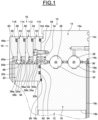
- the rolling bearing as illustrated on Figure 1 is a large-diameter rolling bearing comprising a first ring 10 and a second ring 12.
- the first ring 10 is the outer ring whereas the second ring 12 is the inner ring.
- the rolling bearing may for example be used in a tidal or marine turbine power station a tunnel boring machine, a wind turbine, a big offshore crane or any other applications using a large diameter rolling bearing.
- the outer and inner rings 10, 12 are concentric and extend axially along the bearing rotation axis (not shown) which runs in an axial direction.
- the rings 10, 12 are of the solid type.
- the outer ring 10 comprises a rolling ring 14 and a sealing ring 16 secured to the rolling ring 14.
- the inner ring 12 also comprises a rolling ring 18 and a sealing ring 20 secured to the rolling ring 18.
- the sealing ring 16 of the outer ring radially surrounds the sealing ring 20 of the inner ring.
- the rolling bearing also comprises two rows of balls 22, 24 which are arranged between first raceways 26, 28 of the rolling ring 14 of the outer ring and second raceways 30, 32 of the rolling ring 18 of the inner ring.
- the rolling ring 18 of the inner ring comprises an outer cylindrical surface 18a from which the raceways 30, 32 are formed.
- the raceways 30, 32 are oriented radially outwards.
- the rolling ring 18 also comprises an inner cylindrical surface or bore 18b which is radially opposite to the outer surface 18a.
- the rolling ring 18 further comprises two opposite first and second frontal surfaces 18c, 18d which axially delimit the outer surface 18a and the bore 18b.
- the frontal surfaces 18c, 18d delimit the axial thickness of the rolling ring 18.
- the rolling ring 14 of the outer ring comprises an outer cylindrical surface 14a and an inner cylindrical bore 14b which is radially opposite to the outer surface 14a and from which the raceways 26, 28 are formed.
- the raceways 26, 28 are oriented radially inwards.
- the rolling ring 14 further comprises two opposite first and second frontal surfaces 14c, 14d which axially delimit the outer surface 14a and the bore 14b.
- the frontal surfaces 14c, 14d delimit the axial thickness of the rolling ring 14.
- the rolling bearing further comprises, axially on each side of the rolling rings 14 and 18, an annular seal 34, 36 mounted on the rolling ring 14 and provided to close the radial space that exists between the rolling rings 14, 18.
- This radial space is defined between the bore 14b of the rolling ring 14 and the outer surface 18a of the rolling ring 18.
- An annular closed rolling space (not referenced) is defined between the rolling rings 14, 18 and the seals 34, 36 in which the rows of balls 22, 24 are housed.
- the rolling space is filled with lubricant.
- Each seal 34, 36 is mounted into a groove (not referenced) formed on the cylindrical bore 14b of the rolling ring 14 and comes into contact with the rolling ring 18.
- the seal 34 comes into contact with the outer surface 18a of the rolling ring 18.
- the seal 36 comes into contact with the frontal surface 18c of the rolling ring 18.
- the sealing ring 16 of the outer ring is mounted axially into contact against the frontal surface 14d of the rolling ring 14.
- the sealing ring 16 protrudes axially with regard to the rolling ring 14.
- the sealing ring 16 is reversely attached or secured to the rolling ring 14.
- the sealing ring 16 radially surrounds the sealing ring 20 of the inner ring.
- Each of the sealing rings 16, 20 may be made of stainless steel or treated steel with a painting or anti-corrosion treatment.
- the sealing ring 16 is formed as a split ring and comprises first, second, third and fourth part rings 40 to 46 stacked one relative to the other in the axial direction.
- the sealing ring 16 may be made in one part.
- the first part ring 40 is reversely secured to the rolling ring 14 by screws 48 spaced apart in the circumferential direction.
- the first part ring 40 axially abuts against the frontal surface 14d of the rolling ring 14.
- the second part ring 42 is reversely secured to the first part ring 40 by screws (not shown) axially on the side opposite to the rolling ring 14.
- the third part ring 44 is reversely secured to the second part ring 42 by screws 50 ( Figures 2 and 5 ) axially on the side opposite to the first part ring 40.
- the fourth part ring 46 is reversely secured to the third part ring 44 by screws 52 ( Figure 6 ) axially on the side opposite to the second part ring 42.
- the heads of the screws of the first part ring 40 may be recovered by potting material and embedded inside this material. Hence, the associated threads of the screws are sealed.
- a plurality of successive annular seals are radially provided between the sealing ring 16 of the outer ring and the sealing ring 20 of the inner ring.
- the rolling bearing is provided with first, second, third and fourth successive seals 54 to 60 supported by the sealing ring 16 of the outer ring.
- the sealing ring 16 bears the seals 54 to 60.
- the seals 54 to 60 are arranged successively in the axial direction.
- the first, second, third and fourth successive seals 54 to 60 are respectively mounted on the first, second, third and fourth part rings 40 to 46 of the sealing ring.
- the first seal 54 is axially located on the side of the rolling ring 14
- the fourth seal 60 is axially located on the exterior side of the rolling bearing
- the second and third seals 56, 58 are axially disposed between these two seals.
- the second seal 56 is axially locally inwards with respect to the third and fourth seals 58, 60.
- the first seal 54 is axially locally inwards with respect to the second seal 56.
- Each seal 54 to 60 is provided with an annular heel 54a to 60a and with an annular friction lip 54b to 60b projecting from said heel.
- each friction lip 54b to 60b extends inwardly from the heel 54a to 60a.
- each friction lip 54b to 60b extends obliquely.
- the lips 54b to 58b extend obliquely outwards while the lip 60b extends obliquely inwards.
- each seal is mounted in axial and radial contact against the associated first, second, third and fourth part ring 40 to 46 of the sealing ring.
- the heel 54a of the first seal also axially abuts against the seal 34.
- Each lip 54b to 60b comes into friction contact with the sealing ring 20 of the inner ring.
- the lips 54b to 60b come into friction contact with the outer surface of the sealing ring 20.
- the contact between each lip 54b to 60b and the sealing ring 20 is radial.
- the lips 54b to 60b are flexible in the radial direction.
- the free end of each lip has a triangular shape in cross-section in order to reduce friction.
- the seals 54 to 60 are identical to each other. Alternatively, the seals 54 to 60 may be different to one another. In the illustrated example, the rolling bearing comprises four seals 54 to 60. The number of seals may be different. For example, the rolling bearing may comprise at least two seals.
- the seals 54 to 60 may be made of elastomeric material, for example polyurethane.
- the sealing lips 54b, 56b of the first and second seals delimit between the sealing ring 16 of the outer ring and the sealing ring 20 of the inner ring a first chamber 62.
- the sealing lips 56b, 58b of the second and third seals delimit between the sealing rings 16, 20 a second chamber 64.
- the second chamber 64 is axially offset outward with respect to the first chamber 62.
- the sealing lips 58b, 60b of the third and fourth seals delimit between the sealing rings 16, 20 a third chamber 66.
- the third chamber 66 is axially offset outward with respect to the second chamber 64.
- the chamber 64 is axially located between the first and second chambers 62, 66.
- the first, second and third chambers 62 to 66 are axially successive.
- the sealing ring 20 of the inner ring reversely attached or secured to the rolling ring 18 by screws 68 ( Figure 6 ).
- the heads of the screws 68 may be recovered by potting material and embedded inside this material. Hence, the associated threads of the screws 68 are sealed.
- the sealing ring 20 is mounted axially into contact against the frontal surface 18c of the rolling ring 18.
- the sealing ring 20 protrudes axially with regard to the rolling ring 18.
- the sealing ring 20 comprises an outer cylindrical surface 20a, and an inner cylindrical surface or bore (not referenced) which is radially opposite to the outer surface 20, and two opposite first and second frontal surfaces 20b, 20c which axially delimit the outer surface 20a and the bore.
- the frontal surfaces 20b, 20c delimit the axial thickness of the sealing ring 20.
- the frontal surface 20b of the sealing ring is mounted axially into contact against the frontal surface 18c of the rolling ring 18.
- the friction lips 54b to 60b of the first, second, third and fourth successive seals 54 to 60 come into friction contact with the outer surface 20a of the sealing ring.
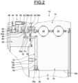
- the rolling bearing comprises a first purging channel 70 provided through the inner ring 12 and in fluidic communication with the first chamber 62 delimited by the sealing lips 54b, 56b of the first and second seals.
- the purging channel 70 enables to evacuate the fluid which can enter inside the sealed chamber 62.
- the purging channel 70 may be used to introduce lubricant, preferably grease, inside the chamber 62. Such lubricant forms an additional barrier against the ingress of contaminants.
- the purging channel 70 is provided through the sealing ring 20 and the rolling ring 18 of the inner ring.
- the purging channel 70 is provided with an inlet orifice 70a opening into the first chamber 62.
- the inlet orifice 70a opens on the outer surface of the sealing ring 20 axially between the sealing lips 54b, 56b of the first and second seals.
- the purging channel 70 is also provided with a first outlet orifice 70b opposite to the inlet orifice 70a and opening on the bore 18b of the rolling ring 18 which is accessible from the outside of the rolling bearing.
- the purging channel 70 is further provided with a second outlet orifice 70c opposite to the inlet orifice 70a and opening on the frontal surface 18c of the rolling ring 18 which is accessible from the outside of the rolling bearing.
- the purging channel 70 may be provided only with the outlet orifice 70b or 70c.
- the purging channel 70 is made of several holes provided into the thickness of the sealing ring 20 and the rolling ring 18.
- the purging channel 70 comprises a first radial hole 72 provided with the inlet orifice 70a and a second axial hole 74 connected to the first radial hole 72, said holes being both formed in the thickness of the sealing ring 20.
- the purging channel 70 may comprise several radial holes 72 each provided with an inlet orifice 70a opening into the first chamber 62 and each connected to the second axial hole 74. In this case, the radial holes 72 are spaced apart in the circumferential direction.
- the purging channel 70 also comprises a third axial hole 76, a fourth radial hole 78 and a fifth axial hole 80 both formed in the thickness of the rolling ring 18.
- the third axial hole 76 axially faces the second axial hole 74
- the fourth radial hole 78 is connected to the third axial hole 76 and provided with the outlet orifice 70b
- the fifth axial hole 80 is connected to the fourth radial hole 78 and provided with the outlet orifice 70c.
- the rolling bearing also comprises a first closing plug 82 attached at the outlet orifice 70b of the purging channel.
- the closing plug 82 may be attached to the outlet orifice 70b by any appropriate means, for example by screwing.
- the closing plug 82 is made of transparent material in order to be able to visually detect the presence of contaminant fluid during an inspection of the rolling bearing.
- the closing plug 82 does not radially protrude with respect to the bore 18b of the rolling ring.
- the closing plug 82 may be recovered by potting material and embedded inside this material. Hence, the associated thread of the closing plug 82 is sealed.
- the purging channel 70 is also provided with the second outlet orifice 70c.
- the rolling bearing may be provided with a plug or with a sensor (not illustrated) mounted at the outlet orifice 70c to detect water.
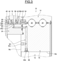
- the rolling bearing comprises a second purging channel 84 provided through the inner ring 12 and in fluidic communication with the second chamber 64 delimited by the sealing lips 56b, 58b of the second and third seals.
- the purging channel 84 enables to evacuate the fluid which can enter inside the sealed chamber 64.
- the purging channel 84 may be used to introduce lubricant, preferably grease, inside the chamber 64. Such lubricant forms an additional barrier against the ingress of contaminants.
- the purging channel 84 is provided through the sealing ring 20 and the rolling ring 18 of the inner ring.
- the purging channel 84 is provided with an inlet orifice 84a opening into the second chamber 64.
- the inlet orifice 84a opens on the outer surface of the sealing ring 20 axially between the sealing lips 56b, 58b of the second and third seals.
- the purging channel 84 is also provided with a first outlet orifice 84b opposite to the inlet orifice 84a and opening on the bore 18b of the rolling ring 18.
- the purging channel 84 is further provided with a second outlet orifice 84c opposite to the inlet orifice 84a and opening on the frontal surface 18c of the rolling ring 18.
- the purging channel 84 may be provided only with the outlet orifice 84b or 84c.
- the purging channel 84 is made of several holes provided into the thickness of the sealing ring 20 and the rolling ring 18.
- the purging channel 84 is offset in the circumferential direction with respect to the purging channel 70.
- the rolling bearing also comprises a second closing plug 86 attached at the outlet orifice 84b of the purging channel.
- the closing plug 86 may be attached to the outlet orifice 84b by any appropriate means, for example by screwing.
- the closing plug 86 is made of transparent material in order to be able to visually detect the presence of contaminant fluid during an inspection of the rolling bearing.
- the closing plug 86 does not radially protrude with respect to the bore 18b of the rolling ring.
- the closing plug 86 may be recovered by potting material and embedded inside this material. Hence, the associated thread of the closing plug 86 is sealed.
- the purging channel 84 is also provided with the second outlet orifice 84c.
- the rolling bearing may be provided with a plug or with a sensor (not illustrated) mounted at the outlet orifice 84c to detect water.
- the rolling bearing comprises a third purging channel 88 provided through the inner ring 12 and in fluidic communication with the third chamber 66 delimited by the sealing lips 58b, 60b of the third and fourth seals.
- the purging channel 88 enables to evacuate the fluid which can enter inside the sealed chamber 66.
- the purging channel 88 may be used to introduce lubricant, preferably grease, inside the chamber 66. Such lubricant forms an additional barrier against the ingress of contaminants.
- lubricant is provided only inside the first and second chambers 62, 64. In such case, the aim of the third purging channel 88 is only to evacuate the fluid which can enter inside the third chamber 66.
- the purging channel 88 is provided through the sealing ring 20 and the rolling ring 18 of the inner ring.
- the purging channel 88 is provided with an inlet orifice 88a opening into the third chamber 66.
- the inlet orifice 88a opens on the outer surface of the sealing ring 20 axially between the sealing lips 58b, 60b of the third and fourth seals.
- the purging channel 88 is also provided with a first outlet orifice 88b opposite to the inlet orifice 88a and opening on the bore 18b of the rolling ring 18.
- the purging channel 88 is further provided with a second outlet orifice 88c opposite to the inlet orifice 88a and opening on the frontal surface 18c of the rolling ring 18.
- the purging channel 84 may be provided only with the outlet orifice 88b or 88c.
- the purging channel 88 is made of several holes provided into the thickness of the sealing ring 20 and the rolling ring 18.
- the purging channel 88 is offset in the circumferential direction with respect to the purging channels 70, 84.
- the purging channels 70, 84 and 88 are distinct from each other. Alternatively, some holes may be shared by at least two of these purging channels, namely the axial hole 76 and radial hole 78.
- each of the purging channels 70, 84 and 88 is provided through the sealing ring 20 and the rolling ring 18 of the inner ring.
- at least one these purging channels 70, 84 and 88 may be provided only through the sealing ring 20.
- the rolling bearing also comprises a third closing plug 89 attached at the outlet orifice 88b of the purging channel.
- the closing plug 89 may be attached to the outlet orifice 88b by any appropriate means, for example by screwing.
- the closing plug 89 is made of transparent material in order to be able to visually detect the presence of contaminant fluid during an inspection of the rolling bearing.
- the closing plug 89 does not radially protrude with respect to the bore 18b of the rolling ring.
- the closing plug 89 may be recovered by potting material and embedded inside this material. Hence, the associated thread of the closing plug 89 is sealed.
- the purging channel 88 is also provided with the second outlet orifice 88c.
- the rolling bearing may be provided with a plug or with a sensor (not illustrated) mounted at the outlet orifice 88c to detect water.
- the rolling bearing is further provided with first, second and third successive annular sealing members 90 to 94 axially interposed between the rolling ring 18 and the sealing ring 20 of the inner ring.
- the sealing members 90 to 94 are arranged successively in the radial direction.
- the sealing members 90 to 94 are axially interposed between the frontal surface 18c of the rolling ring 18 and the frontal surface 20b of sealing ring.
- the rolling ring 18 bears the first sealing member 90 and the sealing ring 20 bears the second and third sealing members 92, 94.
- Grooves are provided on the frontal surfaces 18c, 20b to receive the sealing members 90 to 94.
- the sealing members 90 to 94 have in cross-section a circular shape. Alternatively, the sealing members 90 to 94 may have other shapes.
- the sealing member 90 is radially offset inwards with respect to the sealing member 92, and the sealing member 92 is radially offset inwards with respect to the sealing member 74.
- the rolling bearing comprises three sealing members 90 to 94.
- the number of seals may be different.
- the rolling bearing may comprise only the two sealing members 90 and 92.
- the sealing members 90 to 94 may be made of elastomeric material, for example polyurethane.
- the rolling bearing further comprises a first leakage test channel 96 provided through the inner ring 12.
- the leakage test channel 96 is provided through the rolling ring 18 of the inner ring.
- the leakage test channel 96 is provided with an inlet orifice 96a opening on the frontal surface 18c of the rolling ring in a zone located radially between the sealing members 90, 92.
- the leakage test channel 96 is provided with an outlet orifice 96b opposite to the inlet orifice 96a and opening on the bore 18b of the rolling ring which is accessible from the outside of the rolling bearing.
- the leakage test channel 96 Prior to use of the rolling bearing, the leakage test channel 96 enables to introduce a fluid radially between the sealing members 90, 92 at the junction between the frontal surface 18c of the rolling ring and the frontal surface 20b of the sealing ring. Hence, the efficiency of the sealing members 90, 92 may be tested.
- the introduced fluid may be compressed air, lubricant, coloured liquid, etc.
- the leakage test channel 96 enables to evacuate the fluid which can enter in the zone located radially between the sealing members 90, 92 at the junction between the frontal surface 18c of the rolling ring and the frontal surface 20b of the sealing ring.
- the leakage test channel 96 is made of several holes provided into the thickness of the rolling ring 18.
- the leakage test channel 96 comprises a first axial hole 98 provided with the inlet orifice 96a and a second radial hole 100 connected to the first radial hole 98 and provided with the outlet orifice 96b, said holes being both formed in the thickness of the rolling ring 18.
- the rolling bearing also comprises a fourth closing plug 102 attached at the outlet orifice 96b of the leakage test channel.
- the closing plug 102 may be attached to the outlet orifice 96b by any appropriate means, for example by screwing.
- the closing plug 102 is made of transparent material in order to be able to visually detect the presence of contaminant fluid during an inspection of the rolling bearing.
- the closing plug 102 does not radially protrude with respect to the bore 18b of the rolling ring.
- the closing plug 102 may be recovered by potting material and embedded inside this material. Hence, the associated thread of the closing plug 102 is sealed.
- the leakage test channel 96 is provided through the rolling ring 18 of the inner ring.
- the first leakage test channel 96 may be provided through the sealing ring 20.
- the inlet orifice 96a of the leakage test channel 96 opens on the frontal surface 20b of the sealing ring and the outlet orifice 96b opens on the opposite frontal surface 20c which is accessible from the outside of the rolling bearing.
- the leakage test channel 96 is here made of one single hole provided into the thickness of the sealing ring 20.
- the rolling bearing is further provided with a first seal member 110 axially interposed between the first part ring 40 of the sealing ring and the rolling ring 14 of the outer ring.
- the seal member 110 is axially interposed between the frontal surface 14d of the rolling ring and the frontal surface 40a of the first part ring 40 axially bearing against this frontal surface 14d.
- a groove (not referenced) is provided on this frontal surface 40a of the first part ring 40.
- the first part ring 40 here bears the sealing member 110.
- the rolling ring 14 may bear the sealing member 110.
- the seal member 110 is radially offset outwards with respect to the first seal 54.
- the seal member 110 radially surrounds the first seal 54.
- the rolling bearing is also provided with a second seal member 112 axially interposed between the first and second part rings 40, 42 of the sealing ring.
- the seal member 112 is axially interposed between the frontal surfaces of the first and second part rings 40, 42 in axial contact one against the other.
- a groove (not referenced) is provided on this frontal surface of the second part ring 42.
- the second part ring 42 here bears the sealing member 112.
- the first part ring 40 may bear the sealing member 112.
- the seal member 112 is radially offset outwards with respect to the second seal 56.
- the seal member 112 radially surrounds the second seal 56.
- the rolling bearing is further provided with a third seal member 114 axially interposed between the second and third part rings 42, 44 of the sealing ring.
- the seal member 114 is axially interposed between the frontal surfaces of the second and third part rings 42, 44 in axial contact one against the other.
- a groove (not referenced) is provided on this frontal surface of the third part ring 44.
- the third part ring 44 here bears the sealing member 114.
- the second part ring 42 may bear the sealing member 114.
- the seal member 114 is radially offset outwards with respect to the third seal 58.
- the seal member 114 radially surrounds the third seal 58.
- the rolling bearing is further provided with a fourth seal member 116 axially interposed between the third and fourth part rings 44, 46 of the sealing ring.
- the seal member 116 is axially interposed between the frontal surfaces of the third and fourth part rings 44, 46 in axial contact one against the other.
- a groove (not referenced) is provided on this frontal surface of the fourth part ring 46.
- the fourth part ring 46 here bears the sealing member 116.
- the third part ring 44 may bear the sealing member 116.
- the seal member 116 is radially offset outwards with respect to the fourth seal 60.
- the seal member 116 radially surrounds the fourth seal 60.
- the seal members 110 to 116 are aligned in the axial direction.
- the rolling bearing comprises a second leakage test channel 118 provided through the sealing ring 16 of the outer ring.
- the leakage test channel 118 is provided through the axial thickness of the sealing ring 16.
- the leakage test channel 118 extends axially through the first, second, third and fourth parts 40 to 46 of the sealing ring 16.
- the leakage test channel 118 may be provided through the rolling ring 14.
- the leakage test channel 118 is provided with a first inlet orifice 118a opening on the frontal surface 40a of the first part 40 of the sealing ring, which is in axial contact with the rolling ring 14, in a zone located radially between the sealing member 110 and the seal 54.
- the leakage test channel 118 is also provided with a second inlet orifice 118b opening on the frontal surface of the second part 42 of the sealing ring, which is in axial contact with the first part 40, in a zone located radially between the sealing member 112 and the seal 56.
- the leakage test channel 96 is further provided with a third inlet orifice 118c opening on the frontal surface of the third part 44 of the sealing ring, which is in axial contact with the second part 42, in a zone located radially between the sealing member 114 and the seal 58.
- the leakage test channel 118 is also provided with an outlet orifice 118d opening on the frontal surface of the fourth part 44 of the sealing ring which is oriented axially outwards and accessible from the outside of the rolling bearing.
- the frontal surface 46a is located axially on the side opposite of the third part 44.
- the frontal surfaces 40a, 46a delimit the axial thickness of the sealing ring 16.
- the leakage test channel 118 is made of several axial aligned through-holes provided into the thickness of the sealing ring 16.
- the inlet orifices 118a to 118c and the outlet orifice 118d are aligned in the axial direction.
- the leakage test channel 118 Prior to use of the rolling bearing, the leakage test channel 118 enables to introduce a fluid radially between the sealing member 110 and the seal 54 at the junction between the rolling ring 14 and the first part 40, and radially between the sealing member 112 and the seal 56 at the junction between the first and second parts 40 and 42, and radially between the sealing member 114 and the seal 58 at the junction between the second and third parts 42 and 44, and radially between the sealing member 116 and the seal 60 at the junction between the third and the fourth parts 44, 46.
- the introduced fluid may be compressed air, lubricant, coloured liquid, etc.
- the leakage test channel 118 enables to evacuate the fluid which can enter in the zone located radially between the sealing member 110 and the seal 54 at the junction between the rolling ring 14 and the first part 40, and in the zone located radially between the sealing member 112 and the seal 56 at the junction between the first and second parts 40 and 42, and in the zone located radially between the sealing member 114 and the seal 58 at the junction between the second and third parts 42 and 44, and in the zone located radially between the sealing member 116 and the seal 60 at the junction between the third and the fourth parts 44, 46.
- the rolling bearing also comprises a fifth closing plug 120 attached at the outlet orifice 118b of the leakage test channel.
- the closing plug 120 may be attached to the outlet orifice 118b by any appropriate means, for example by screwing.
- the closing plug 120 is made of transparent material in order to be able to visually detect the presence of contaminant fluid during an inspection of the rolling bearing.
- the closing plug 120 axially protrudes with respect to the frontal surface 46a of the fourth part 46 of the sealing ring.
- the closing plug 120 may be recovered by potting material and embedded inside this material. Hence, the associated thread of the closing plug 120 is sealed.
- the rolling bearing further comprises a third leakage test channel 122 provided through the rolling ring 18 of the inner ring
- the leakage test channel 122 is provided with an inlet orifice 122a opening on the frontal surface 18c of the rolling ring in a zone radially offset inward with respect to the sealing ring 20.
- the leakage test channel 122 is provided with an outlet orifice 122b opposite to the inlet orifice 122a and opening on the bore 18b of the rolling ring.
- the leakage test channel 122 is made of several holes provided into the thickness of the rolling ring 18.
- the leakage test channel 122 comprises a first axial hole (not referenced) provided with the inlet orifice 122a and a second radial hole (not referenced) connected to the first radial hole and provided with the outlet orifice 122b, said holes being both formed in the thickness of the rolling ring 18.
- the zone of the frontal surface 18c of the rolling ring onto which opens the inlet orifice 122a is intended to be in axial contact with a frame of the associated machine (not referenced) provided with two seals.
- the inlet orifice 122a is radially located between these two seals.
- the leakage test channel 112 Prior to use, the leakage test channel 112 enables to introduce a fluid radially between these seals to test their efficiency.
- the introduced fluid may be compressed air, lubricant, coloured liquid, etc.
- the leakage test channel 112 enables to evacuate the fluid which can enter in the zone located radially between these seals at the junction between the frontal surface 18c of the rolling ring and the frame of the associated machine.
- the rolling bearing also comprises a fifth closing plug 124 attached at the outlet orifice 112b of the leakage test channel.
- the closing plug 124 may be attached to the outlet orifice 112b by any appropriate means, for example by screwing.
- the closing plug 124 is made of transparent material in order to be able to visually detect the presence of contaminant fluid during an inspection.
- the closing plug 124 does not radially protrude with respect to the bore 18b of the rolling ring.
- the closing plug 124 may be recovered by potting material and embedded inside this material. Hence, the associated thread of the closing plug 124 is sealed.
- the rolling bearing may be deprived of the first leakage test channel and/or the second leakage test channel and/or the third leakage test channel.
- the example shown on Figure 9 differs from the first example in that the sealing ring 16 of the outer ring is further provided with a spacer 130 interposed axially between the rolling ring 14 and the first part ring 40.
- the first seal 54 is axially spaced with respect the seal 34.
- the axial length of the sealing ring 20 of the inner ring is increased.
- the spacer 130 allows the sealing lips of the seals 54 to 60 to adopt two different axial positions, namely the first one with this spacer and the second one with the removing of the spacer and the axial contact of the first part 40 directly against the rolling ring 14.
- the seals 54 to 60 are axially displaced along the outer surface 20a of the sealing ring of the inner ring.
- the first ring of the rolling bearing is the outer ring whereas the second ring is the inner ring.
- the rolling bearing comprises two rows of rolling elements.
- the rolling bearing may comprise only one row of rolling elements, or three or more rows of rolling elements.
- the rolling elements are balls.
- the rolling bearing may comprise other types of rolling elements, for example rollers.
Landscapes
- Engineering & Computer Science (AREA)
- General Engineering & Computer Science (AREA)
- Mechanical Engineering (AREA)
- Rolling Contact Bearings (AREA)
Abstract
Description
- The present invention relates to the field of rolling bearings.
- The invention particularly relates to the field of large-diameter rolling bearings having an inner ring and an outer ring arranged concentrically about an axis of rotation running in an axial direction.
- Such large-diameter rolling bearings may be used for example in marine applications, for example in a tidal or marine turbine power station, or in a tunnel boring machine, or in a mining extraction machine or in a wind turbine.
- A large-diameter rolling bearing generally comprises two concentric inner and outer rings, and at least one row of rolling elements, such as rollers or balls, arranged between the rings. The bearing also comprises seals disposed between the inner and outer rings to define a closed space inside which the rolling elements are arranged.
- Large-diameter rolling bearings are generally used in aggressive environments, in particular in marine applications. Seals prevent exterior elements, such as dust, abrasive particles, water and marine species, for example plankton and algae, from getting inside said bearing and damaging its components. Those exterior elements may also alter the seal itself, leading to a reduction in the seal service life.
- Generally, a plurality of additional adjacent seals is provided on the bearing front side which is directly in contact with the aggressive environments, for example with the saltwater. These additional seals are fixed to a sealing ring of one of the inner and outer rings and comprise a sealing lip in sliding contact with a running surface of a sealing ring of the other ring. Hence, several adjacent closed outer chambers are delimited between the sealing lips of the adjacent seals.
- If water starts to enter inside the rolling bearing, by first entering inside the first outer seal chamber, it is desired to prevent the water or pollution to move further inside the bearing until the rolling space.
- This water ingress problem can occur in most of the applications, but in particular for immerged applications such as in a tidal turbine.
- One aim of the present invention is to overcome this drawback.
- The invention relates to a rolling bearing comprising a first ring and a second ring capable of rotating concentrically relative to one another, and at least one row of rolling elements arranged between first and second raceways of the said first and second rings.
- The first ring comprises at least one first rolling ring provided with said first raceway and at least one first sealing ring secured to the first rolling ring. The second ring comprises at least one second rolling ring provided with said second raceway and at least one second sealing ring secured to the second rolling ring.
- The rolling bearing further comprises at least first and second successive seals supported by said first sealing ring of the first ring and each provided with at least one sealing lip coming into contact with said second sealing ring of the second ring, the sealing lips of said first and second successive seals delimiting between said first and second sealing rings a first chamber.
- According to a general feature, at least a first purging channel is provided through the second ring and comprises at least one inlet orifice opening into the first chamber and at least one outlet orifice opening on a surface of the second ring which is accessible from the outside of the rolling bearing.
- Thanks to the invention, in case some fluid such water enters the first sealed chamber, it is evacuated through the first purging channel until the outlet orifice(s). This leads to optimize sealing performance of the first and second successive seals and to avoid to change these seals too often.
- The fluid can circulate through the first purging channel thanks to the gravity force and/or under the effect of a pump connected to the outlet orifice(s).
- In one embodiment, said first purging channel is provided through said second sealing ring and said second rolling ring of the second ring, the surface onto which opens said outlet orifice of said first purging channel is located on said second rolling ring.
- Alternatively, said first purging channel may be provided only through said second sealing ring of the second ring. In this case, the surface onto which opens said outlet orifice of said first purging channel is located on said second sealing ring.
- In one embodiment, the rolling bearing further comprises at least one closing element reversely attached at said outlet orifice of said first purging channel.
- Preferably, the closing element is made of transparent material so that one can visually detect the presence of contaminant fluid during an inspection of the bearing. In such case, the closing element can be removed and placed back in position after the fluid has been purged.
- The closing element may be a plug. Alternatively, the closing element may be a collector to collect fluid.
- The rolling bearing may further comprise at least a third seal supported by said first sealing ring of the first ring and provided with at least one sealing lip coming into contact with said second sealing ring of the second ring, the sealing lips of said second and third seals delimiting between said first and second sealing rings a second chamber, and at least a second purging channel being provided through the second ring and comprising at least one inlet orifice opening into the second chamber and at least one outlet orifice opening on a surface of the second ring which is accessible from the outside of the rolling bearing. Said second purging channel is distinct from said first second purging channel.
- In one embodiment, said second purging channel is provided through said second sealing ring and said second rolling ring, the surface onto which opens said outlet orifice of said first purging channel is located on said second rolling ring. Alternatively, said second purging channel may be provided only through said second sealing ring of the second ring.
- In one embodiment, the rolling bearing further comprises at least one closing element reversely attached at said outlet orifice of said second purging channel. Preferably, this closing element is made of transparent material. This closing element may be a plug. Alternatively, the closing element may be a collector to collect fluid.
- In one embodiment, the rolling bearing further comprises at least first and second successive sealing members axially interposed between said second rolling ring and said second sealing ring of the second ring, and at least one first leakage channel provided through said second rolling ring, or through said second sealing ring, and comprising at least one inlet orifice opening on a frontal surface of said second rolling ring, or of said second sealing ring, in a zone located radially between the first and second successive sealing members and at least one outlet orifice opening on a surface of said second rolling ring, or of said second sealing ring, which is accessible from the outside of the rolling bearing.
- The rolling bearing may further comprise at least one closing element reversely attached at said outlet orifice of said first leakage channel. Preferably, this closing element is made of transparent material. This closing element may be a plug. Alternatively, the closing element may be a collector to collect fluid.
- In one embodiment, the rolling bearing further comprises at least a first seal member axially interposed between said first rolling ring and said first sealing ring of the first ring and radially offset with respect to the first seal, and at least one second leakage channel provided through said first rolling ring, or through said first sealing ring, and comprising at least one inlet orifice opening on a frontal surface of said first rolling ring, or of said first sealing ring, in a zone located radially between the first seal member and the first seal, and at least one outlet orifice opening on a surface of said first rolling ring, or of said first sealing ring, which is accessible from the outside of the rolling bearing. The rolling bearing may further comprise at least one closing element reversely attached at said outlet orifice of said second leakage channel. Preferably, this closing element is made of transparent material. This closing element may be a plug. Alternatively, the closing element may be a collector to collect fluid.
- In one embodiment, said first sealing ring of the first ring is formed as a split ring and comprises at least a first part ring and a second part ring axially stacked, the first and second successive seals being respectively supported by the first and second part rings, the first seal member being axially interposed between said first rolling ring and the first part ring of said first sealing ring of the first ring. Said second leakage channel may extend axially through the first and second part rings of said first sealing ring.
- In one embodiment, the rolling bearing further comprises, axially on each side of said first and second rolling rings of the first and second rings, seals delimiting radially between said first and second rolling rings a closed rolling space inside which is housed said row of rolling elements, said seals being distinct from the first and second successive seals.
- In one embodiment, the first ring is the inner ring and the second ring is the outer ring. Alternatively, the first ring is the outer ring and the second ring is the inner ring.
- The present invention and its advantages will be better understood by studying the detailed description of specific embodiments given by way of non-limiting examples and illustrated by the appended drawings on which:
-
Figure 1 is a cross-section of a rolling bearing according to a first example of the invention, -
Figures 2 to 4 are partial cross-sections of the rolling bearing ofFigure 1 according to other cutting planes, -
Figures 5 to 7 are cross-sections of the rolling bearing ofFigure 1 according to other cutting planes, -
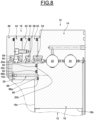
Figure 8 is a cross-section of a rolling bearing according to a second example of the invention, and -
Figure 9 is a cross-section of a rolling bearing according to a third example of the invention. - The rolling bearing as illustrated on
Figure 1 is a large-diameter rolling bearing comprising afirst ring 10 and asecond ring 12. In the illustrated example, thefirst ring 10 is the outer ring whereas thesecond ring 12 is the inner ring. The rolling bearing may for example be used in a tidal or marine turbine power station a tunnel boring machine, a wind turbine, a big offshore crane or any other applications using a large diameter rolling bearing. - The outer and
inner rings rings - The
outer ring 10 comprises arolling ring 14 and asealing ring 16 secured to the rollingring 14. Theinner ring 12 also comprises a rollingring 18 and a sealingring 20 secured to the rollingring 18. The sealingring 16 of the outer ring radially surrounds the sealingring 20 of the inner ring. - As will be described later, a plurality of successive seals are radially provided between the sealing rings 16, 20.
- In the illustrated example, the rolling bearing also comprises two rows of
balls first raceways ring 14 of the outer ring andsecond raceways ring 18 of the inner ring. - The rolling
ring 18 of the inner ring comprises an outercylindrical surface 18a from which theraceways raceways ring 18 also comprises an inner cylindrical surface or bore 18b which is radially opposite to theouter surface 18a. The rollingring 18 further comprises two opposite first and secondfrontal surfaces 18c, 18d which axially delimit theouter surface 18a and thebore 18b. Thefrontal surfaces 18c, 18d delimit the axial thickness of the rollingring 18. - The rolling
ring 14 of the outer ring comprises an outercylindrical surface 14a and an innercylindrical bore 14b which is radially opposite to theouter surface 14a and from which theraceways raceways ring 14 further comprises two opposite first and secondfrontal surfaces outer surface 14a and thebore 14b. Thefrontal surfaces ring 14. - The rolling bearing further comprises, axially on each side of the rolling rings 14 and 18, an
annular seal ring 14 and provided to close the radial space that exists between the rolling rings 14, 18. This radial space is defined between the bore 14b of the rollingring 14 and theouter surface 18a of the rollingring 18. An annular closed rolling space (not referenced) is defined between the rolling rings 14, 18 and theseals balls - Each
seal cylindrical bore 14b of the rollingring 14 and comes into contact with the rollingring 18. Theseal 34 comes into contact with theouter surface 18a of the rollingring 18. Theseal 36 comes into contact with thefrontal surface 18c of the rollingring 18. Alternatively, it could be possible to provide a reversed arrangement for at least one of theseals ring 18 and coming into friction contact with the rollingring 14. - The sealing
ring 16 of the outer ring is mounted axially into contact against thefrontal surface 14d of the rollingring 14. The sealingring 16 protrudes axially with regard to the rollingring 14. The sealingring 16 is reversely attached or secured to the rollingring 14. The sealingring 16 radially surrounds the sealingring 20 of the inner ring. Each of the sealing rings 16, 20 may be made of stainless steel or treated steel with a painting or anti-corrosion treatment. - In the illustrated example, the sealing
ring 16 is formed as a split ring and comprises first, second, third and fourth part rings 40 to 46 stacked one relative to the other in the axial direction. Alternatively, the sealingring 16 may be made in one part. - The
first part ring 40 is reversely secured to the rollingring 14 byscrews 48 spaced apart in the circumferential direction. Thefirst part ring 40 axially abuts against thefrontal surface 14d of the rollingring 14. Similarly, thesecond part ring 42 is reversely secured to thefirst part ring 40 by screws (not shown) axially on the side opposite to the rollingring 14. Thethird part ring 44 is reversely secured to thesecond part ring 42 by screws 50 (Figures 2 and5 ) axially on the side opposite to thefirst part ring 40. Thefourth part ring 46 is reversely secured to thethird part ring 44 by screws 52 (Figure 6 ) axially on the side opposite to thesecond part ring 42. The heads of the screws of thefirst part ring 40 may be recovered by potting material and embedded inside this material. Hence, the associated threads of the screws are sealed. - As previously mentioned, a plurality of successive annular seals are radially provided between the sealing
ring 16 of the outer ring and the sealingring 20 of the inner ring. - In the illustrated example, the rolling bearing is provided with first, second, third and fourth
successive seals 54 to 60 supported by the sealingring 16 of the outer ring. The sealingring 16 bears theseals 54 to 60. Theseals 54 to 60 are arranged successively in the axial direction. - The first, second, third and fourth
successive seals 54 to 60 are respectively mounted on the first, second, third and fourth part rings 40 to 46 of the sealing ring. Hence, thefirst seal 54 is axially located on the side of the rollingring 14, thefourth seal 60 is axially located on the exterior side of the rolling bearing, and the second andthird seals second seal 56 is axially locally inwards with respect to the third andfourth seals first seal 54 is axially locally inwards with respect to thesecond seal 56. - Each
seal 54 to 60 is provided with anannular heel 54a to 60a and with anannular friction lip 54b to 60b projecting from said heel. In the illustrated example, eachfriction lip 54b to 60b extends inwardly from theheel 54a to 60a. Here, eachfriction lip 54b to 60b extends obliquely. In the illustrated example, thelips 54b to 58b extend obliquely outwards while thelip 60b extends obliquely inwards. - The
heel 54a to 60a of each seal is mounted in axial and radial contact against the associated first, second, third andfourth part ring 40 to 46 of the sealing ring. Here, theheel 54a of the first seal also axially abuts against theseal 34. - Each
lip 54b to 60b comes into friction contact with the sealingring 20 of the inner ring. Thelips 54b to 60b come into friction contact with the outer surface of the sealingring 20. The contact between eachlip 54b to 60b and the sealingring 20 is radial. Thelips 54b to 60b are flexible in the radial direction. Preferably, the free end of each lip has a triangular shape in cross-section in order to reduce friction. - In the illustrated example, the
seals 54 to 60 are identical to each other. Alternatively, theseals 54 to 60 may be different to one another. In the illustrated example, the rolling bearing comprises fourseals 54 to 60. The number of seals may be different. For example, the rolling bearing may comprise at least two seals. Theseals 54 to 60 may be made of elastomeric material, for example polyurethane. - The sealing
lips ring 16 of the outer ring and the sealingring 20 of the inner ring afirst chamber 62. - Similarly, the sealing
lips second chamber 64. Thesecond chamber 64 is axially offset outward with respect to thefirst chamber 62. The sealinglips third chamber 66. Thethird chamber 66 is axially offset outward with respect to thesecond chamber 64. Thechamber 64 is axially located between the first andsecond chambers third chambers 62 to 66 are axially successive. - The sealing
ring 20 of the inner ring reversely attached or secured to the rollingring 18 by screws 68 (Figure 6 ). The heads of thescrews 68 may be recovered by potting material and embedded inside this material. Hence, the associated threads of thescrews 68 are sealed. The sealingring 20 is mounted axially into contact against thefrontal surface 18c of the rollingring 18. The sealingring 20 protrudes axially with regard to the rollingring 18. - The sealing
ring 20 comprises an outercylindrical surface 20a, and an inner cylindrical surface or bore (not referenced) which is radially opposite to theouter surface 20, and two opposite first and secondfrontal surfaces outer surface 20a and the bore. Thefrontal surfaces ring 20. Thefrontal surface 20b of the sealing ring is mounted axially into contact against thefrontal surface 18c of the rollingring 18. Thefriction lips 54b to 60b of the first, second, third and fourthsuccessive seals 54 to 60 come into friction contact with theouter surface 20a of the sealing ring. - As shown on
Figure 2 , the rolling bearing comprises afirst purging channel 70 provided through theinner ring 12 and in fluidic communication with thefirst chamber 62 delimited by the sealinglips channel 70 enables to evacuate the fluid which can enter inside the sealedchamber 62. Prior to use, the purgingchannel 70 may be used to introduce lubricant, preferably grease, inside thechamber 62. Such lubricant forms an additional barrier against the ingress of contaminants. - In the illustrated example, the purging
channel 70 is provided through the sealingring 20 and the rollingring 18 of the inner ring. The purgingchannel 70 is provided with aninlet orifice 70a opening into thefirst chamber 62. Theinlet orifice 70a opens on the outer surface of the sealingring 20 axially between the sealinglips - The purging
channel 70 is also provided with afirst outlet orifice 70b opposite to theinlet orifice 70a and opening on thebore 18b of the rollingring 18 which is accessible from the outside of the rolling bearing. In the illustrated example, the purgingchannel 70 is further provided with asecond outlet orifice 70c opposite to theinlet orifice 70a and opening on thefrontal surface 18c of the rollingring 18 which is accessible from the outside of the rolling bearing. Alternatively, the purgingchannel 70 may be provided only with theoutlet orifice - The purging
channel 70 is made of several holes provided into the thickness of the sealingring 20 and the rollingring 18. The purgingchannel 70 comprises a first radial hole 72 provided with theinlet orifice 70a and a secondaxial hole 74 connected to the first radial hole 72, said holes being both formed in the thickness of the sealingring 20. Alternatively, the purgingchannel 70 may comprise several radial holes 72 each provided with aninlet orifice 70a opening into thefirst chamber 62 and each connected to the secondaxial hole 74. In this case, the radial holes 72 are spaced apart in the circumferential direction. - The purging
channel 70 also comprises a third axial hole 76, a fourthradial hole 78 and a fifthaxial hole 80 both formed in the thickness of the rollingring 18. The third axial hole 76 axially faces the secondaxial hole 74, the fourthradial hole 78 is connected to the third axial hole 76 and provided with theoutlet orifice 70b, and the fifthaxial hole 80 is connected to the fourthradial hole 78 and provided with theoutlet orifice 70c. - The rolling bearing also comprises a
first closing plug 82 attached at theoutlet orifice 70b of the purging channel. Theclosing plug 82 may be attached to theoutlet orifice 70b by any appropriate means, for example by screwing. Preferably, theclosing plug 82 is made of transparent material in order to be able to visually detect the presence of contaminant fluid during an inspection of the rolling bearing. In the illustrated example, theclosing plug 82 does not radially protrude with respect to thebore 18b of the rolling ring. Theclosing plug 82 may be recovered by potting material and embedded inside this material. Hence, the associated thread of theclosing plug 82 is sealed. - As previously mentioned, in the illustrated example, the purging
channel 70 is also provided with thesecond outlet orifice 70c. The rolling bearing may be provided with a plug or with a sensor (not illustrated) mounted at theoutlet orifice 70c to detect water. - As shown on
Figure 3 , the rolling bearing comprises asecond purging channel 84 provided through theinner ring 12 and in fluidic communication with thesecond chamber 64 delimited by the sealinglips channel 84 enables to evacuate the fluid which can enter inside the sealedchamber 64. Prior to use, the purgingchannel 84 may be used to introduce lubricant, preferably grease, inside thechamber 64. Such lubricant forms an additional barrier against the ingress of contaminants. - In the illustrated example, the purging
channel 84 is provided through the sealingring 20 and the rollingring 18 of the inner ring. The purgingchannel 84 is provided with aninlet orifice 84a opening into thesecond chamber 64. Theinlet orifice 84a opens on the outer surface of the sealingring 20 axially between the sealinglips - The purging
channel 84 is also provided with afirst outlet orifice 84b opposite to theinlet orifice 84a and opening on thebore 18b of the rollingring 18. In the illustrated example, the purgingchannel 84 is further provided with a second outlet orifice 84c opposite to theinlet orifice 84a and opening on thefrontal surface 18c of the rollingring 18. Alternatively, the purgingchannel 84 may be provided only with theoutlet orifice 84b or 84c. - Similarly to the purging
channel 70, the purgingchannel 84 is made of several holes provided into the thickness of the sealingring 20 and the rollingring 18. The purgingchannel 84 is offset in the circumferential direction with respect to the purgingchannel 70. - The rolling bearing also comprises a
second closing plug 86 attached at theoutlet orifice 84b of the purging channel. Theclosing plug 86 may be attached to theoutlet orifice 84b by any appropriate means, for example by screwing. Preferably, theclosing plug 86 is made of transparent material in order to be able to visually detect the presence of contaminant fluid during an inspection of the rolling bearing. In the illustrated example, theclosing plug 86 does not radially protrude with respect to thebore 18b of the rolling ring. Theclosing plug 86 may be recovered by potting material and embedded inside this material. Hence, the associated thread of theclosing plug 86 is sealed. - As previously mentioned, in the illustrated example, the purging
channel 84 is also provided with the second outlet orifice 84c. The rolling bearing may be provided with a plug or with a sensor (not illustrated) mounted at the outlet orifice 84c to detect water. - As shown on
Figure 4 , the rolling bearing comprises athird purging channel 88 provided through theinner ring 12 and in fluidic communication with thethird chamber 66 delimited by the sealinglips channel 88 enables to evacuate the fluid which can enter inside the sealedchamber 66. Prior to use, the purgingchannel 88 may be used to introduce lubricant, preferably grease, inside thechamber 66. Such lubricant forms an additional barrier against the ingress of contaminants. In a preferred embodiment, lubricant is provided only inside the first andsecond chambers third purging channel 88 is only to evacuate the fluid which can enter inside thethird chamber 66. - In the illustrated example, the purging
channel 88 is provided through the sealingring 20 and the rollingring 18 of the inner ring. The purgingchannel 88 is provided with aninlet orifice 88a opening into thethird chamber 66. Theinlet orifice 88a opens on the outer surface of the sealingring 20 axially between the sealinglips - The purging
channel 88 is also provided with afirst outlet orifice 88b opposite to theinlet orifice 88a and opening on thebore 18b of the rollingring 18. In the illustrated example, the purgingchannel 88 is further provided with a second outlet orifice 88c opposite to theinlet orifice 88a and opening on thefrontal surface 18c of the rollingring 18. Alternatively, the purgingchannel 84 may be provided only with theoutlet orifice 88b or 88c. - Similarly to the purging
channels channel 88 is made of several holes provided into the thickness of the sealingring 20 and the rollingring 18. The purgingchannel 88 is offset in the circumferential direction with respect to the purgingchannels - In the illustrated example, the purging
channels radial hole 78. - In the illustrated example, each of the purging
channels ring 20 and the rollingring 18 of the inner ring. Alternatively, at least one these purgingchannels ring 20. - The rolling bearing also comprises a
third closing plug 89 attached at theoutlet orifice 88b of the purging channel. Theclosing plug 89 may be attached to theoutlet orifice 88b by any appropriate means, for example by screwing. Preferably, theclosing plug 89 is made of transparent material in order to be able to visually detect the presence of contaminant fluid during an inspection of the rolling bearing. In the illustrated example, theclosing plug 89 does not radially protrude with respect to thebore 18b of the rolling ring. Theclosing plug 89 may be recovered by potting material and embedded inside this material. Hence, the associated thread of theclosing plug 89 is sealed. - As previously mentioned, in the illustrated example, the purging
channel 88 is also provided with the second outlet orifice 88c. The rolling bearing may be provided with a plug or with a sensor (not illustrated) mounted at the outlet orifice 88c to detect water. - As shown notably on
Figures 1 and5 , in the illustrated example, the rolling bearing is further provided with first, second and third successiveannular sealing members 90 to 94 axially interposed between the rollingring 18 and the sealingring 20 of the inner ring. The sealingmembers 90 to 94 are arranged successively in the radial direction. - The sealing
members 90 to 94 are axially interposed between thefrontal surface 18c of the rollingring 18 and thefrontal surface 20b of sealing ring. Here, the rollingring 18 bears the first sealingmember 90 and the sealingring 20 bears the second andthird sealing members members 90 to 94 on the rolling and sealing rings 18, 20. Grooves (not referenced) are provided on thefrontal surfaces members 90 to 94. In the illustrated example, the sealingmembers 90 to 94 have in cross-section a circular shape. Alternatively, the sealingmembers 90 to 94 may have other shapes. - The sealing
member 90 is radially offset inwards with respect to the sealingmember 92, and the sealingmember 92 is radially offset inwards with respect to the sealingmember 74. - In the illustrated example, the rolling bearing comprises three sealing
members 90 to 94. The number of seals may be different. For example, the rolling bearing may comprise only the two sealingmembers members 90 to 94 may be made of elastomeric material, for example polyurethane. - The rolling bearing further comprises a first
leakage test channel 96 provided through theinner ring 12. In the illustrated example, theleakage test channel 96 is provided through the rollingring 18 of the inner ring. - The
leakage test channel 96 is provided with aninlet orifice 96a opening on thefrontal surface 18c of the rolling ring in a zone located radially between the sealingmembers leakage test channel 96 is provided with anoutlet orifice 96b opposite to theinlet orifice 96a and opening on thebore 18b of the rolling ring which is accessible from the outside of the rolling bearing. - Prior to use of the rolling bearing, the
leakage test channel 96 enables to introduce a fluid radially between the sealingmembers frontal surface 18c of the rolling ring and thefrontal surface 20b of the sealing ring. Hence, the efficiency of the sealingmembers - In use, the
leakage test channel 96 enables to evacuate the fluid which can enter in the zone located radially between the sealingmembers frontal surface 18c of the rolling ring and thefrontal surface 20b of the sealing ring. - The
leakage test channel 96 is made of several holes provided into the thickness of the rollingring 18. Theleakage test channel 96 comprises a first axial hole 98 provided with theinlet orifice 96a and a secondradial hole 100 connected to the first radial hole 98 and provided with theoutlet orifice 96b, said holes being both formed in the thickness of the rollingring 18. - The rolling bearing also comprises a
fourth closing plug 102 attached at theoutlet orifice 96b of the leakage test channel. Theclosing plug 102 may be attached to theoutlet orifice 96b by any appropriate means, for example by screwing. Preferably, theclosing plug 102 is made of transparent material in order to be able to visually detect the presence of contaminant fluid during an inspection of the rolling bearing. In the illustrated example, theclosing plug 102 does not radially protrude with respect to thebore 18b of the rolling ring. Theclosing plug 102 may be recovered by potting material and embedded inside this material. Hence, the associated thread of theclosing plug 102 is sealed. - As previously mentioned, in the illustrated example, the
leakage test channel 96 is provided through the rollingring 18 of the inner ring. Alternatively, as shown onFigure 8 , the firstleakage test channel 96 may be provided through the sealingring 20. - In this alternative embodiment, the
inlet orifice 96a of theleakage test channel 96 opens on thefrontal surface 20b of the sealing ring and theoutlet orifice 96b opens on the oppositefrontal surface 20c which is accessible from the outside of the rolling bearing. Theleakage test channel 96 is here made of one single hole provided into the thickness of the sealingring 20. - Referring once again to
Figures 1 and6 , in the first illustrated example, the rolling bearing is further provided with afirst seal member 110 axially interposed between thefirst part ring 40 of the sealing ring and the rollingring 14 of the outer ring. Theseal member 110 is axially interposed between thefrontal surface 14d of the rolling ring and thefrontal surface 40a of thefirst part ring 40 axially bearing against thisfrontal surface 14d. A groove (not referenced) is provided on thisfrontal surface 40a of thefirst part ring 40. Hence, thefirst part ring 40 here bears the sealingmember 110. Alternatively, the rollingring 14 may bear the sealingmember 110. Theseal member 110 is radially offset outwards with respect to thefirst seal 54. Theseal member 110 radially surrounds thefirst seal 54. - The rolling bearing is also provided with a
second seal member 112 axially interposed between the first and second part rings 40, 42 of the sealing ring. Theseal member 112 is axially interposed between the frontal surfaces of the first and second part rings 40, 42 in axial contact one against the other. A groove (not referenced) is provided on this frontal surface of thesecond part ring 42. Hence, thesecond part ring 42 here bears the sealingmember 112. Alternatively, thefirst part ring 40 may bear the sealingmember 112. Theseal member 112 is radially offset outwards with respect to thesecond seal 56. Theseal member 112 radially surrounds thesecond seal 56. - The rolling bearing is further provided with a
third seal member 114 axially interposed between the second and third part rings 42, 44 of the sealing ring. Theseal member 114 is axially interposed between the frontal surfaces of the second and third part rings 42, 44 in axial contact one against the other. A groove (not referenced) is provided on this frontal surface of thethird part ring 44. Hence, thethird part ring 44 here bears the sealingmember 114. Alternatively, thesecond part ring 42 may bear the sealingmember 114. Theseal member 114 is radially offset outwards with respect to thethird seal 58. Theseal member 114 radially surrounds thethird seal 58. - The rolling bearing is further provided with a
fourth seal member 116 axially interposed between the third and fourth part rings 44, 46 of the sealing ring. Theseal member 116 is axially interposed between the frontal surfaces of the third and fourth part rings 44, 46 in axial contact one against the other. A groove (not referenced) is provided on this frontal surface of thefourth part ring 46. Hence, thefourth part ring 46 here bears the sealingmember 116. Alternatively, thethird part ring 44 may bear the sealingmember 116. Theseal member 116 is radially offset outwards with respect to thefourth seal 60. Theseal member 116 radially surrounds thefourth seal 60. Theseal members 110 to 116 are aligned in the axial direction. - The rolling bearing comprises a second
leakage test channel 118 provided through the sealingring 16 of the outer ring. Theleakage test channel 118 is provided through the axial thickness of the sealingring 16. Theleakage test channel 118 extends axially through the first, second, third andfourth parts 40 to 46 of the sealingring 16. Alternatively, theleakage test channel 118 may be provided through the rollingring 14. - The
leakage test channel 118 is provided with afirst inlet orifice 118a opening on thefrontal surface 40a of thefirst part 40 of the sealing ring, which is in axial contact with the rollingring 14, in a zone located radially between the sealingmember 110 and theseal 54. - The
leakage test channel 118 is also provided with asecond inlet orifice 118b opening on the frontal surface of thesecond part 42 of the sealing ring, which is in axial contact with thefirst part 40, in a zone located radially between the sealingmember 112 and theseal 56. Theleakage test channel 96 is further provided with athird inlet orifice 118c opening on the frontal surface of thethird part 44 of the sealing ring, which is in axial contact with thesecond part 42, in a zone located radially between the sealingmember 114 and theseal 58. - The
leakage test channel 118 is also provided with anoutlet orifice 118d opening on the frontal surface of thefourth part 44 of the sealing ring which is oriented axially outwards and accessible from the outside of the rolling bearing. Thefrontal surface 46a is located axially on the side opposite of thethird part 44. Thefrontal surfaces ring 16. Theleakage test channel 118 is made of several axial aligned through-holes provided into the thickness of the sealingring 16. Theinlet orifices 118a to 118c and theoutlet orifice 118d are aligned in the axial direction. - Prior to use of the rolling bearing, the
leakage test channel 118 enables to introduce a fluid radially between the sealingmember 110 and theseal 54 at the junction between the rollingring 14 and thefirst part 40, and radially between the sealingmember 112 and theseal 56 at the junction between the first andsecond parts member 114 and theseal 58 at the junction between the second andthird parts member 116 and theseal 60 at the junction between the third and thefourth parts members 110 to 116 and theseals 54 to 60 may be tested. The introduced fluid may be compressed air, lubricant, coloured liquid, etc. - In use, the
leakage test channel 118 enables to evacuate the fluid which can enter in the zone located radially between the sealingmember 110 and theseal 54 at the junction between the rollingring 14 and thefirst part 40, and in the zone located radially between the sealingmember 112 and theseal 56 at the junction between the first andsecond parts member 114 and theseal 58 at the junction between the second andthird parts member 116 and theseal 60 at the junction between the third and thefourth parts - The rolling bearing also comprises a
fifth closing plug 120 attached at theoutlet orifice 118b of the leakage test channel. Theclosing plug 120 may be attached to theoutlet orifice 118b by any appropriate means, for example by screwing. Preferably, theclosing plug 120 is made of transparent material in order to be able to visually detect the presence of contaminant fluid during an inspection of the rolling bearing. In the illustrated example, theclosing plug 120 axially protrudes with respect to thefrontal surface 46a of thefourth part 46 of the sealing ring. Theclosing plug 120 may be recovered by potting material and embedded inside this material. Hence, the associated thread of theclosing plug 120 is sealed. - As shown on
Figure 7 , in the illustrated example, the rolling bearing further comprises a thirdleakage test channel 122 provided through the rollingring 18 of the inner ring - The
leakage test channel 122 is provided with aninlet orifice 122a opening on thefrontal surface 18c of the rolling ring in a zone radially offset inward with respect to the sealingring 20. Theleakage test channel 122 is provided with anoutlet orifice 122b opposite to theinlet orifice 122a and opening on thebore 18b of the rolling ring. Theleakage test channel 122 is made of several holes provided into the thickness of the rollingring 18. Theleakage test channel 122 comprises a first axial hole (not referenced) provided with theinlet orifice 122a and a second radial hole (not referenced) connected to the first radial hole and provided with theoutlet orifice 122b, said holes being both formed in the thickness of the rollingring 18. - The zone of the
frontal surface 18c of the rolling ring onto which opens theinlet orifice 122a is intended to be in axial contact with a frame of the associated machine (not referenced) provided with two seals. Theinlet orifice 122a is radially located between these two seals. - Prior to use, the
leakage test channel 112 enables to introduce a fluid radially between these seals to test their efficiency. The introduced fluid may be compressed air, lubricant, coloured liquid, etc. - In use, the
leakage test channel 112 enables to evacuate the fluid which can enter in the zone located radially between these seals at the junction between thefrontal surface 18c of the rolling ring and the frame of the associated machine. - The rolling bearing also comprises a
fifth closing plug 124 attached at the outlet orifice 112b of the leakage test channel. Theclosing plug 124 may be attached to the outlet orifice 112b by any appropriate means, for example by screwing. Preferably, theclosing plug 124 is made of transparent material in order to be able to visually detect the presence of contaminant fluid during an inspection. In the illustrated example, theclosing plug 124 does not radially protrude with respect to thebore 18b of the rolling ring. Theclosing plug 124 may be recovered by potting material and embedded inside this material. Hence, the associated thread of theclosing plug 124 is sealed. - Alternatively, the rolling bearing may be deprived of the first leakage test channel and/or the second leakage test channel and/or the third leakage test channel.
- The example shown on
Figure 9 , in which identical parts are given identical references, differs from the first example in that the sealingring 16 of the outer ring is further provided with aspacer 130 interposed axially between the rollingring 14 and thefirst part ring 40. Here, thefirst seal 54 is axially spaced with respect theseal 34. In this example, the axial length of the sealingring 20 of the inner ring is increased. - The
spacer 130 allows the sealing lips of theseals 54 to 60 to adopt two different axial positions, namely the first one with this spacer and the second one with the removing of the spacer and the axial contact of thefirst part 40 directly against the rollingring 14. By removing thespacer 130, theseals 54 to 60 are axially displaced along theouter surface 20a of the sealing ring of the inner ring. - Otherwise, as previously mentioned, in the illustrated examples, the first ring of the rolling bearing is the outer ring whereas the second ring is the inner ring. As an alternative, it could be possible to provide a reversed arrangement with the first ring forming the inner ring and the second ring forming the outer ring.
- In the described examples, the rolling bearing comprises two rows of rolling elements. Alternatively, the rolling bearing may comprise only one row of rolling elements, or three or more rows of rolling elements. In the illustrated example, the rolling elements are balls. The rolling bearing may comprise other types of rolling elements, for example rollers.
Claims (10)
- Rolling bearing comprising a first ring (10) and a second ring (12) capable of rotating concentrically relative to one another, and at least one row of rolling elements (22) arranged between first and second raceways (26, 30) of the said first and second rings, the first ring (10) comprising at least one first rolling ring (14) provided with said first raceway (26) and at least one first sealing ring (16) secured to the first rolling ring, and the second ring (12) comprising at least one second rolling ring (18) provided with said second raceway (30) and at least one second sealing ring (20) secured to the second rolling ring, the rolling bearing further comprising at least first and second successive seals (54, 56) supported by said first sealing ring (16) of the first ring and each provided with at least one sealing lip (54b, 56b) coming into contact with said second sealing ring (20) of the second ring, the sealing lips (54b, 56b) of said first and second successive seals delimiting between said first and second sealing rings (16, 20) a first chamber (62), characterized in that at least a first purging channel (70) is provided through the second ring (12) and comprises at least one inlet orifice (70a) opening into the first chamber (62) and at least one outlet orifice (70b) opening on a surface (18b) of the second ring which is accessible from the outside of the rolling bearing.
- Rolling bearing according to claim 1, wherein said first purging channel (70) is provided through said second sealing ring (20) and said second rolling ring (18) of the second ring, the surface onto which opens said outlet orifice (70b) of said first purging channel is located on said second rolling ring (18).
- Rolling bearing according to claim 1 or 2, further comprising at least one closing element (82) reversely attached at said outlet orifice (70b) of said first purging channel.
- Rolling bearing according to claim 3, wherein said closing element (82) is made of transparent material.
- Rolling bearing according to any of the preceding claims, further comprising at least a third seal (58) supported by said first sealing ring (16) of the first ring and provided with at least one sealing lip (58b) coming into contact with said second sealing ring (20) of the second ring, the sealing lips (56b, 58b) of said second and third seals delimiting between said first and second sealing rings (16, 20) a second chamber (64), and at least a second purging channel (84) being provided through the second ring (12) and comprising at least one inlet orifice (84a) opening into the second chamber (64) and at least one outlet orifice (84b) opening on a surface (18b) of the second ring which is accessible from the outside of the rolling bearing.
- Rolling bearing according to any of the preceding claims, further comprising at least first and second successive sealing members (90, 92) axially interposed between said second rolling ring (18) and said second sealing ring (20) of the second ring, and at least one leakage channel (96) provided through said second rolling ring (18), or said second sealing ring (20), and comprising at least one inlet orifice (96a) opening on a frontal surface of said second rolling ring, or said second sealing ring, in a zone located radially between the first and second successive sealing members and at least one outlet orifice (96b) opening on a surface (18b) of said second rolling ring, or said second sealing ring, which is accessible from the outside of the rolling bearing.
- Rolling bearing according to any of the preceding claims, further comprising at least a first seal member (110) axially interposed between said first rolling ring (14) and said first sealing ring (16) of the first ring and radially offset with respect to the first seal (54), and at least one leakage channel (118) provided through said first rolling ring (14), or said first sealing ring (16), and comprising at least one inlet orifice (118a) opening on a frontal surface of said first rolling ring (14), or said first sealing ring (16), in a zone located radially between the first seal member (110) and the first seal (54) and at least one outlet orifice (118d) opening on a surface of the said first rolling ring, or said first sealing ring, which is accessible from the outside of the rolling bearing.
- Rolling bearing according to claim 7, wherein said first sealing ring (16) of the first ring is formed as a split ring and comprises at least a first part ring (40) and a second part ring (40) axially stacked, the first and second successive seals (54, 56) being respectively supported by the first and second part rings (40, 42), the first seal member (110) being axially interposed between said first rolling ring (14) and the first part ring (40) of said first sealing ring (16) of the first ring.
- Rolling bearing according to claim 8, wherein said leakage channel (118) extends axially through the first and second part rings (40, 42) of said first sealing ring (16).
- Rolling bearing according to any of the preceding claims, further comprising, axially on each side of said first and second rolling rings (14, 18) of the first and second rings, seals (34, 36) delimiting radially between said first and second rolling rings a closed rolling space inside which is housed said row of rolling elements (22), said seals (34, 36) being distinct from the first and second successive seals (54, 56).
Applications Claiming Priority (1)
| Application Number | Priority Date | Filing Date | Title |
|---|---|---|---|
| DE102022214026.5A DE102022214026A1 (en) | 2022-12-20 | 2022-12-20 | Rolling bearings with seals and flushing channel |
Publications (2)
| Publication Number | Publication Date |
|---|---|
| EP4390167A1 true EP4390167A1 (en) | 2024-06-26 |
| EP4390167B1 EP4390167B1 (en) | 2025-09-10 |
Family
ID=89222906
Family Applications (1)
| Application Number | Title | Priority Date | Filing Date |
|---|---|---|---|
| EP23216754.4A Active EP4390167B1 (en) | 2022-12-20 | 2023-12-14 | Rolling bearing with seals and purging channel |
Country Status (5)
| Country | Link |
|---|---|
| US (1) | US12584524B2 (en) |
| EP (1) | EP4390167B1 (en) |
| CN (1) | CN118224193A (en) |
| DE (1) | DE102022214026A1 (en) |
| ES (1) | ES3057907T3 (en) |
Cited By (1)
| Publication number | Priority date | Publication date | Assignee | Title |
|---|---|---|---|---|
| GB2632188A (en) * | 2023-07-27 | 2025-01-29 | Skf Ab | Rolling bearing comprising two identical rings |
Families Citing this family (2)
| Publication number | Priority date | Publication date | Assignee | Title |
|---|---|---|---|---|
| DE102022214026A1 (en) | 2022-12-20 | 2024-06-20 | Aktiebolaget Skf | Rolling bearings with seals and flushing channel |
| DE102024204232A1 (en) * | 2024-05-07 | 2025-11-13 | Aktiebolaget Skf | Rolling bearings with seals and an intermediate perforated spacer ring |
Citations (5)
| Publication number | Priority date | Publication date | Assignee | Title |
|---|---|---|---|---|
| DE3742079A1 (en) * | 1987-12-11 | 1989-06-22 | Blohm Voss Ag | ARRANGEMENT FOR SEALING A PROPELLER SHAFT OF A SHIP |
| WO2010040027A2 (en) * | 2008-10-02 | 2010-04-08 | The Timken Company | Grease purge system |
| DE102009021322A1 (en) * | 2009-05-11 | 2010-12-02 | Blohm + Voss Industries Gmbh | Arrangement for sealing waves |
| US20140346738A1 (en) * | 2013-05-22 | 2014-11-27 | Skf Blohm + Voss Industries Gmbh | Seal Apparatus for a Ship Propeller Shaft and Method of Making the Apparatus |
| GB2573194A (en) * | 2018-04-24 | 2019-10-30 | Skf Ab | Slewing bearing with sealing arrangement |
Family Cites Families (14)
| Publication number | Priority date | Publication date | Assignee | Title |
|---|---|---|---|---|
| US3019065A (en) * | 1959-11-09 | 1962-01-30 | Howard B Neeley | Grease container |
| US4395140A (en) | 1981-10-02 | 1983-07-26 | Rotek Incorporated | Bearing mounting with hydraulic fastening means for cranes and the like |
| DE102010018255A1 (en) * | 2010-04-23 | 2011-10-27 | Imo Holding Gmbh | Sealing arrangement for rolling bearings |
| DE202011110128U1 (en) | 2011-04-05 | 2012-12-19 | Imo Holding Gmbh | Slewing connection for underwater operation |
| JP6041861B2 (en) * | 2011-04-05 | 2016-12-14 | テュッセンクルップ ローテ エルデ ゲーエムベーハー | Oil lubricated anti-friction bearing |
| DE102015209428B4 (en) * | 2015-05-22 | 2023-01-05 | Aktiebolaget Skf | Sealing arrangement for sealing a space between a housing and a component against a liquid medium and turbine hub |
| CN104895726B (en) * | 2015-07-02 | 2017-10-27 | 国电联合动力技术有限公司 | A kind of tidal power unit and its pitch variable bearings |
| FR3068757B1 (en) | 2017-07-05 | 2020-06-26 | Ge Energy Power Conversion Technology Limited | SEALING DEVICE FOR A PROPELLING SHAFT OF A MARINE VEHICLE PROPULSION UNIT |
| FR3070741B1 (en) | 2017-09-01 | 2019-10-18 | Aetc Sapphire | ANNULAR JOINT FOR IMPLEMENTING ROTATING SEAL BETWEEN TWO CYLINDRICAL ELEMENTS |
| DE102018201885A1 (en) | 2018-02-07 | 2019-08-08 | Aktiebolaget Skf | Sealed storage module |
| DE102018213356A1 (en) | 2018-04-24 | 2019-10-24 | Aktiebolaget Skf | Swivel bearing with seal arrangement |
| DE102019217411A1 (en) * | 2019-11-12 | 2021-05-12 | Aktiebolaget Skf | Bearing with at least one sealing element and at least one adjusting washer for an axial displacement of the sealing element |
| DE102021204102A1 (en) | 2021-04-26 | 2022-10-27 | Skf Lubrication Systems Germany Gmbh | lubricant pump arrangement |
| DE102022214026A1 (en) | 2022-12-20 | 2024-06-20 | Aktiebolaget Skf | Rolling bearings with seals and flushing channel |
-
2022
- 2022-12-20 DE DE102022214026.5A patent/DE102022214026A1/en active Pending
-
2023
- 2023-12-06 US US18/530,351 patent/US12584524B2/en active Active
- 2023-12-14 ES ES23216754T patent/ES3057907T3/en active Active
- 2023-12-14 EP EP23216754.4A patent/EP4390167B1/en active Active
- 2023-12-18 CN CN202311737253.2A patent/CN118224193A/en active Pending
Patent Citations (5)
| Publication number | Priority date | Publication date | Assignee | Title |
|---|---|---|---|---|
| DE3742079A1 (en) * | 1987-12-11 | 1989-06-22 | Blohm Voss Ag | ARRANGEMENT FOR SEALING A PROPELLER SHAFT OF A SHIP |
| WO2010040027A2 (en) * | 2008-10-02 | 2010-04-08 | The Timken Company | Grease purge system |
| DE102009021322A1 (en) * | 2009-05-11 | 2010-12-02 | Blohm + Voss Industries Gmbh | Arrangement for sealing waves |
| US20140346738A1 (en) * | 2013-05-22 | 2014-11-27 | Skf Blohm + Voss Industries Gmbh | Seal Apparatus for a Ship Propeller Shaft and Method of Making the Apparatus |
| GB2573194A (en) * | 2018-04-24 | 2019-10-30 | Skf Ab | Slewing bearing with sealing arrangement |
Cited By (2)
| Publication number | Priority date | Publication date | Assignee | Title |
|---|---|---|---|---|
| GB2632188A (en) * | 2023-07-27 | 2025-01-29 | Skf Ab | Rolling bearing comprising two identical rings |
| US12663045B2 (en) | 2023-07-27 | 2026-06-23 | Aktiebolaget Skf | Rolling bearing comprising two identical rings |
Also Published As
| Publication number | Publication date |
|---|---|
| ES3057907T3 (en) | 2026-03-05 |
| US12584524B2 (en) | 2026-03-24 |
| CN118224193A (en) | 2024-06-21 |
| EP4390167B1 (en) | 2025-09-10 |
| DE102022214026A1 (en) | 2024-06-20 |
| US20240200606A1 (en) | 2024-06-20 |
Similar Documents
| Publication | Publication Date | Title |
|---|---|---|
| EP4390167B1 (en) | Rolling bearing with seals and purging channel | |
| EP4390164B1 (en) | Rolling bearing with seals and leakage channel | |
| EP4390166B1 (en) | Rolling bearing with seals and purging channel | |
| US11022176B2 (en) | Slewing bearing with sealing arrangement | |
| US11486444B2 (en) | Bearing with at least one sealing element and at least one adjusting shim for axially displacing said sealing element | |
| US6263752B1 (en) | Transmission for automobiles and bearing therefor | |
| CA1227510A (en) | Clearance seal for rotating shafts | |
| EP2383482A1 (en) | Rolling bearing device with fluid bypass passage-ways. | |
| US20250347323A1 (en) | Rolling bearing with seals and a segmented spacer ring between the seals | |
| US7008113B2 (en) | Roller bearing in a deep-drilling apparatus | |
| US11585379B2 (en) | Bearing with removable sealing module | |
| US6739757B2 (en) | Bearing unit | |
| US20250035163A1 (en) | Rolling bearing comprising two identical rings | |
| US11852197B2 (en) | Rolling bearing with removable sealing module | |
| US20250347321A1 (en) | Rolling bearing with seals and a perforated spacer ring between the seals | |
| GB2633201A (en) | Rolling bearing comprising holes and grooves | |
| GB2573194A (en) | Slewing bearing with sealing arrangement | |
| JP2005061575A (en) | Rolling bearing | |
| GB2700423A (en) | Rolling bearing with seals and perforated spacer ring between said seals | |
| US20240035513A1 (en) | Union with integrated needle roller bearings | |
| US10323691B2 (en) | Needle bush bearing with sealing device | |
| JPH01105003A (en) | Vane type rotary actuator | |
| Hirota et al. | Seal assembly |
Legal Events
| Date | Code | Title | Description |
|---|---|---|---|
| PUAI | Public reference made under article 153(3) epc to a published international application that has entered the european phase |
Free format text: ORIGINAL CODE: 0009012 |
|
| STAA | Information on the status of an ep patent application or granted ep patent |
Free format text: STATUS: THE APPLICATION HAS BEEN PUBLISHED |
|
| AK | Designated contracting states |
Kind code of ref document: A1 Designated state(s): AL AT BE BG CH CY CZ DE DK EE ES FI FR GB GR HR HU IE IS IT LI LT LU LV MC ME MK MT NL NO PL PT RO RS SE SI SK SM TR |
|
| STAA | Information on the status of an ep patent application or granted ep patent |
Free format text: STATUS: REQUEST FOR EXAMINATION WAS MADE |
|
| 17P | Request for examination filed |
Effective date: 20241115 |
|
| RBV | Designated contracting states (corrected) |
Designated state(s): AL AT BE BG CH CY CZ DE DK EE ES FI FR GB GR HR HU IE IS IT LI LT LU LV MC ME MK MT NL NO PL PT RO RS SE SI SK SM TR |
|
| GRAP | Despatch of communication of intention to grant a patent |
Free format text: ORIGINAL CODE: EPIDOSNIGR1 |
|
| STAA | Information on the status of an ep patent application or granted ep patent |
Free format text: STATUS: GRANT OF PATENT IS INTENDED |
|
| INTG | Intention to grant announced |
Effective date: 20250407 |
|
| GRAS | Grant fee paid |
Free format text: ORIGINAL CODE: EPIDOSNIGR3 |
|
| GRAA | (expected) grant |
Free format text: ORIGINAL CODE: 0009210 |
|
| STAA | Information on the status of an ep patent application or granted ep patent |
Free format text: STATUS: THE PATENT HAS BEEN GRANTED |
|
| AK | Designated contracting states |
Kind code of ref document: B1 Designated state(s): AL AT BE BG CH CY CZ DE DK EE ES FI FR GB GR HR HU IE IS IT LI LT LU LV MC ME MK MT NL NO PL PT RO RS SE SI SK SM TR |
|
| REG | Reference to a national code |
Ref country code: GB Ref legal event code: FG4D |
|
| REG | Reference to a national code |
Ref country code: CH Ref legal event code: EP |
|
| REG | Reference to a national code |
Ref country code: DE Ref legal event code: R096 Ref document number: 602023006576 Country of ref document: DE |
|
| REG | Reference to a national code |
Ref country code: IE Ref legal event code: FG4D |
|
| P01 | Opt-out of the competence of the unified patent court (upc) registered |
Free format text: CASE NUMBER: UPC_APP_7352_4390167/2025 Effective date: 20250917 |
|
| PG25 | Lapsed in a contracting state [announced via postgrant information from national office to epo] |
Ref country code: NO Free format text: LAPSE BECAUSE OF FAILURE TO SUBMIT A TRANSLATION OF THE DESCRIPTION OR TO PAY THE FEE WITHIN THE PRESCRIBED TIME-LIMIT Effective date: 20251210 |
|
| REG | Reference to a national code |
Ref country code: LT Ref legal event code: MG9D |
|
| PGFP | Annual fee paid to national office [announced via postgrant information from national office to epo] |
Ref country code: AT Payment date: 20260113 Year of fee payment: 3 |
|
| PG25 | Lapsed in a contracting state [announced via postgrant information from national office to epo] |
Ref country code: FI Free format text: LAPSE BECAUSE OF FAILURE TO SUBMIT A TRANSLATION OF THE DESCRIPTION OR TO PAY THE FEE WITHIN THE PRESCRIBED TIME-LIMIT Effective date: 20250910 |
|
| REG | Reference to a national code |
Ref country code: NL Ref legal event code: MP Effective date: 20250910 |
|
| PG25 | Lapsed in a contracting state [announced via postgrant information from national office to epo] |
Ref country code: HR Free format text: LAPSE BECAUSE OF FAILURE TO SUBMIT A TRANSLATION OF THE DESCRIPTION OR TO PAY THE FEE WITHIN THE PRESCRIBED TIME-LIMIT Effective date: 20250910 |
|
| PGFP | Annual fee paid to national office [announced via postgrant information from national office to epo] |
Ref country code: FR Payment date: 20251223 Year of fee payment: 3 |
|
| PG25 | Lapsed in a contracting state [announced via postgrant information from national office to epo] |
Ref country code: GR Free format text: LAPSE BECAUSE OF FAILURE TO SUBMIT A TRANSLATION OF THE DESCRIPTION OR TO PAY THE FEE WITHIN THE PRESCRIBED TIME-LIMIT Effective date: 20251211 |
|
| PG25 | Lapsed in a contracting state [announced via postgrant information from national office to epo] |
Ref country code: SE Free format text: LAPSE BECAUSE OF FAILURE TO SUBMIT A TRANSLATION OF THE DESCRIPTION OR TO PAY THE FEE WITHIN THE PRESCRIBED TIME-LIMIT Effective date: 20250910 |
|
| PG25 | Lapsed in a contracting state [announced via postgrant information from national office to epo] |
Ref country code: LV Free format text: LAPSE BECAUSE OF FAILURE TO SUBMIT A TRANSLATION OF THE DESCRIPTION OR TO PAY THE FEE WITHIN THE PRESCRIBED TIME-LIMIT Effective date: 20250910 |
|
| PG25 | Lapsed in a contracting state [announced via postgrant information from national office to epo] |
Ref country code: BG Free format text: LAPSE BECAUSE OF FAILURE TO SUBMIT A TRANSLATION OF THE DESCRIPTION OR TO PAY THE FEE WITHIN THE PRESCRIBED TIME-LIMIT Effective date: 20250910 Ref country code: PL Free format text: LAPSE BECAUSE OF FAILURE TO SUBMIT A TRANSLATION OF THE DESCRIPTION OR TO PAY THE FEE WITHIN THE PRESCRIBED TIME-LIMIT Effective date: 20250910 |
|
| PG25 | Lapsed in a contracting state [announced via postgrant information from national office to epo] |
Ref country code: RS Free format text: LAPSE BECAUSE OF FAILURE TO SUBMIT A TRANSLATION OF THE DESCRIPTION OR TO PAY THE FEE WITHIN THE PRESCRIBED TIME-LIMIT Effective date: 20251210 |
|
| REG | Reference to a national code |
Ref country code: AT Ref legal event code: MK05 Ref document number: 1836165 Country of ref document: AT Kind code of ref document: T Effective date: 20250910 |
|
| PG25 | Lapsed in a contracting state [announced via postgrant information from national office to epo] |
Ref country code: NL Free format text: LAPSE BECAUSE OF FAILURE TO SUBMIT A TRANSLATION OF THE DESCRIPTION OR TO PAY THE FEE WITHIN THE PRESCRIBED TIME-LIMIT Effective date: 20250910 |
|
| REG | Reference to a national code |
Ref country code: ES Ref legal event code: FG2A Ref document number: 3057907 Country of ref document: ES Kind code of ref document: T3 Effective date: 20260305 |
|
| PG25 | Lapsed in a contracting state [announced via postgrant information from national office to epo] |
Ref country code: SM Free format text: LAPSE BECAUSE OF FAILURE TO SUBMIT A TRANSLATION OF THE DESCRIPTION OR TO PAY THE FEE WITHIN THE PRESCRIBED TIME-LIMIT Effective date: 20250910 |
|
| PGFP | Annual fee paid to national office [announced via postgrant information from national office to epo] |
Ref country code: ES Payment date: 20260122 Year of fee payment: 3 |
|
| PGFP | Annual fee paid to national office [announced via postgrant information from national office to epo] |
Ref country code: DE Payment date: 20251229 Year of fee payment: 3 |
|
| PG25 | Lapsed in a contracting state [announced via postgrant information from national office to epo] |
Ref country code: AT Free format text: LAPSE BECAUSE OF FAILURE TO SUBMIT A TRANSLATION OF THE DESCRIPTION OR TO PAY THE FEE WITHIN THE PRESCRIBED TIME-LIMIT Effective date: 20250910 |
|
| PG25 | Lapsed in a contracting state [announced via postgrant information from national office to epo] |
Ref country code: IT Free format text: LAPSE BECAUSE OF FAILURE TO SUBMIT A TRANSLATION OF THE DESCRIPTION OR TO PAY THE FEE WITHIN THE PRESCRIBED TIME-LIMIT Effective date: 20250910 Ref country code: RO Free format text: LAPSE BECAUSE OF FAILURE TO SUBMIT A TRANSLATION OF THE DESCRIPTION OR TO PAY THE FEE WITHIN THE PRESCRIBED TIME-LIMIT Effective date: 20250910 |
|
| PG25 | Lapsed in a contracting state [announced via postgrant information from national office to epo] |
Ref country code: IS Free format text: LAPSE BECAUSE OF FAILURE TO SUBMIT A TRANSLATION OF THE DESCRIPTION OR TO PAY THE FEE WITHIN THE PRESCRIBED TIME-LIMIT Effective date: 20260110 |
|
| PG25 | Lapsed in a contracting state [announced via postgrant information from national office to epo] |
Ref country code: CZ Free format text: LAPSE BECAUSE OF FAILURE TO SUBMIT A TRANSLATION OF THE DESCRIPTION OR TO PAY THE FEE WITHIN THE PRESCRIBED TIME-LIMIT Effective date: 20250910 Ref country code: PT Free format text: LAPSE BECAUSE OF FAILURE TO SUBMIT A TRANSLATION OF THE DESCRIPTION OR TO PAY THE FEE WITHIN THE PRESCRIBED TIME-LIMIT Effective date: 20260112 |
|
| PG25 | Lapsed in a contracting state [announced via postgrant information from national office to epo] |
Ref country code: SK Free format text: LAPSE BECAUSE OF FAILURE TO SUBMIT A TRANSLATION OF THE DESCRIPTION OR TO PAY THE FEE WITHIN THE PRESCRIBED TIME-LIMIT Effective date: 20250910 Ref country code: EE Free format text: LAPSE BECAUSE OF FAILURE TO SUBMIT A TRANSLATION OF THE DESCRIPTION OR TO PAY THE FEE WITHIN THE PRESCRIBED TIME-LIMIT Effective date: 20250910 |
|
| REG | Reference to a national code |
Ref country code: DE Ref legal event code: R097 Ref document number: 602023006576 Country of ref document: DE |
|
| PG25 | Lapsed in a contracting state [announced via postgrant information from national office to epo] |
Ref country code: LT Free format text: LAPSE BECAUSE OF FAILURE TO SUBMIT A TRANSLATION OF THE DESCRIPTION OR TO PAY THE FEE WITHIN THE PRESCRIBED TIME-LIMIT Effective date: 20250910 |
|
| PG25 | Lapsed in a contracting state [announced via postgrant information from national office to epo] |
Ref country code: MC Free format text: LAPSE BECAUSE OF FAILURE TO SUBMIT A TRANSLATION OF THE DESCRIPTION OR TO PAY THE FEE WITHIN THE PRESCRIBED TIME-LIMIT Effective date: 20250910 |
|
| PG25 | Lapsed in a contracting state [announced via postgrant information from national office to epo] |
Ref country code: DK Free format text: LAPSE BECAUSE OF FAILURE TO SUBMIT A TRANSLATION OF THE DESCRIPTION OR TO PAY THE FEE WITHIN THE PRESCRIBED TIME-LIMIT Effective date: 20250910 |
|
| PLBE | No opposition filed within time limit |
Free format text: ORIGINAL CODE: 0009261 |
|
| STAA | Information on the status of an ep patent application or granted ep patent |
Free format text: STATUS: NO OPPOSITION FILED WITHIN TIME LIMIT |
|
| REG | Reference to a national code |
Ref country code: CH Ref legal event code: L10 Free format text: ST27 STATUS EVENT CODE: U-0-0-L10-L00 (AS PROVIDED BY THE NATIONAL OFFICE) Effective date: 20260722 |