EP2383482A1 - Rolling bearing device with fluid bypass passage-ways. - Google Patents
Rolling bearing device with fluid bypass passage-ways. Download PDFInfo
- Publication number
- EP2383482A1 EP2383482A1 EP11163684A EP11163684A EP2383482A1 EP 2383482 A1 EP2383482 A1 EP 2383482A1 EP 11163684 A EP11163684 A EP 11163684A EP 11163684 A EP11163684 A EP 11163684A EP 2383482 A1 EP2383482 A1 EP 2383482A1
- Authority
- EP
- European Patent Office
- Prior art keywords
- fixed
- rolling bearing
- bearing ring
- ring
- outer ring
- Prior art date
- Legal status (The legal status is an assumption and is not a legal conclusion. Google has not performed a legal analysis and makes no representation as to the accuracy of the status listed.)
- Granted
Links
Images


Classifications
-
- F—MECHANICAL ENGINEERING; LIGHTING; HEATING; WEAPONS; BLASTING
- F16—ENGINEERING ELEMENTS AND UNITS; GENERAL MEASURES FOR PRODUCING AND MAINTAINING EFFECTIVE FUNCTIONING OF MACHINES OR INSTALLATIONS; THERMAL INSULATION IN GENERAL
- F16C—SHAFTS; FLEXIBLE SHAFTS; ELEMENTS OR CRANKSHAFT MECHANISMS; ROTARY BODIES OTHER THAN GEARING ELEMENTS; BEARINGS
- F16C37/00—Cooling of bearings
- F16C37/007—Cooling of bearings of rolling bearings
-
- F—MECHANICAL ENGINEERING; LIGHTING; HEATING; WEAPONS; BLASTING
- F16—ENGINEERING ELEMENTS AND UNITS; GENERAL MEASURES FOR PRODUCING AND MAINTAINING EFFECTIVE FUNCTIONING OF MACHINES OR INSTALLATIONS; THERMAL INSULATION IN GENERAL
- F16C—SHAFTS; FLEXIBLE SHAFTS; ELEMENTS OR CRANKSHAFT MECHANISMS; ROTARY BODIES OTHER THAN GEARING ELEMENTS; BEARINGS
- F16C19/00—Bearings with rolling contact, for exclusively rotary movement
- F16C19/52—Bearings with rolling contact, for exclusively rotary movement with devices affected by abnormal or undesired conditions
-
- F—MECHANICAL ENGINEERING; LIGHTING; HEATING; WEAPONS; BLASTING
- F16—ENGINEERING ELEMENTS AND UNITS; GENERAL MEASURES FOR PRODUCING AND MAINTAINING EFFECTIVE FUNCTIONING OF MACHINES OR INSTALLATIONS; THERMAL INSULATION IN GENERAL
- F16C—SHAFTS; FLEXIBLE SHAFTS; ELEMENTS OR CRANKSHAFT MECHANISMS; ROTARY BODIES OTHER THAN GEARING ELEMENTS; BEARINGS
- F16C33/00—Parts of bearings; Special methods for making bearings or parts thereof
- F16C33/30—Parts of ball or roller bearings
- F16C33/58—Raceways; Race rings
- F16C33/583—Details of specific parts of races
- F16C33/586—Details of specific parts of races outside the space between the races, e.g. end faces or bore of inner ring
-
- F—MECHANICAL ENGINEERING; LIGHTING; HEATING; WEAPONS; BLASTING
- F16—ENGINEERING ELEMENTS AND UNITS; GENERAL MEASURES FOR PRODUCING AND MAINTAINING EFFECTIVE FUNCTIONING OF MACHINES OR INSTALLATIONS; THERMAL INSULATION IN GENERAL
- F16C—SHAFTS; FLEXIBLE SHAFTS; ELEMENTS OR CRANKSHAFT MECHANISMS; ROTARY BODIES OTHER THAN GEARING ELEMENTS; BEARINGS
- F16C41/00—Other accessories, e.g. devices integrated in the bearing not relating to the bearing function as such
- F16C41/005—Fluid passages not relating to lubrication or cooling
-
- F—MECHANICAL ENGINEERING; LIGHTING; HEATING; WEAPONS; BLASTING
- F16—ENGINEERING ELEMENTS AND UNITS; GENERAL MEASURES FOR PRODUCING AND MAINTAINING EFFECTIVE FUNCTIONING OF MACHINES OR INSTALLATIONS; THERMAL INSULATION IN GENERAL
- F16C—SHAFTS; FLEXIBLE SHAFTS; ELEMENTS OR CRANKSHAFT MECHANISMS; ROTARY BODIES OTHER THAN GEARING ELEMENTS; BEARINGS
- F16C2300/00—Application independent of particular apparatuses
- F16C2300/40—Application independent of particular apparatuses related to environment, i.e. operating conditions
- F16C2300/64—Application independent of particular apparatuses related to environment, i.e. operating conditions high pressure, e.g. elements exposed to high pressure gases or fluids
-
- F—MECHANICAL ENGINEERING; LIGHTING; HEATING; WEAPONS; BLASTING
- F16—ENGINEERING ELEMENTS AND UNITS; GENERAL MEASURES FOR PRODUCING AND MAINTAINING EFFECTIVE FUNCTIONING OF MACHINES OR INSTALLATIONS; THERMAL INSULATION IN GENERAL
- F16C—SHAFTS; FLEXIBLE SHAFTS; ELEMENTS OR CRANKSHAFT MECHANISMS; ROTARY BODIES OTHER THAN GEARING ELEMENTS; BEARINGS
- F16C33/00—Parts of bearings; Special methods for making bearings or parts thereof
- F16C33/72—Sealings
- F16C33/76—Sealings of ball or roller bearings
- F16C33/80—Labyrinth sealings
Definitions
- the invention relates to a rolling bearing device.
- An aspect of the invention relates to a rolling bearing device, including: a fixed member; a fixed bearing ring that is fixed to the fixed member; a rotating bearing ring that is arranged so as to face the fixed bearing ring in a radial direction of the rolling bearing and that is fixed to a rotating member; a rolling element that is rollably arranged at a position between the fixed bearing ring and the rotating bearing ring in the radial direction; and a seal member that seals up an annular space between the fixed bearing ring and the rotating bearing ring.
- An escape passage through which fluid is circulated in an axial direction of the rolling bearing so as to be allowed to escape is formed in at least one of a contact portion of the fixed member and a contact portion of the fixed bearing ring, the fixed member and the fixed bearing ring contacting each other at the contact portions.
- FIG. 1 is a sectional view schematically showing a rolling bearing device according to the embodiment of the invention.
- FIG 2 is a sectional view taken along the line II-II in FIG 1 .
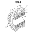
- FIG. 3 is a perspective view showing a rolling bearing 10.
- FIG 4 is a perspective view showing the rolling bearing 10 cut along a plane that passes the axis of the rolling bearing 10.
- the rolling bearing device according to the embodiment includes the rolling bearing 10 fitted to a housing 20.
- the rolling bearing 10 is a ball bearing that includes an inner ring 11, an outer ring 12, balls 13 that are provided between the inner ring 11 and the outer ring 12 and that serve as rolling elements, and a retainer 14 that retains the balls 13.
- the inner ring 11 is formed into an annular shape.
- a recessed inner ring raceway surface 16 is formed in substantially the axial center portion of the outer peripheral surface of the inner ring 11 so as to extend along the whole circumference of the outer peripheral surface.
- a rotating shaft (rotating member) 17 is fitted and fixed to the inner peripheral surface of the inner ring 11. As the rotating shaft 17 rotates, the inner ring 11 rotates together with the rotating shaft 17. Therefore, the inner ring 11 according to the embodiment may constitute a rotating bearing ring according to the invention.
- the outer ring 12 as well as the inner ring 11 is formed into an annular shape.
- the outer ring 12 is arranged on the radially outer side of the inner ring 11 so as to be coaxial with the inner ring 11.
- a recessed outer ring raceway surface 19 is formed in substantially the axial center portion of the inner peripheral surface of the outer ring 12 so as to extend along the whole circumference of the inner peripheral surface.
- the outer ring 12 is fixed when the outer peripheral surface thereof is fitted to the housing (fixed member) 20. Therefore, the outer ring 12 in the embodiment may constitute a fixed bearing ring according to the invention.
- the retainer 14 is an annular member made of synthetic resin, for example, phenol resin.
- the retainer 14 has a plurality of pockets 22 used to house the balls 13 and formed at regular intervals in the circumferential direction.
- the balls 13 are housed in the respective pockets 22 of the retainer 14 so as to be retained at predetermined intervals in the circumferential direction.
- the balls 13 roll at positions between the inner ring raceway surface 16 and the outer ring raceway surface 19.
- Two annular seal members 24 are fitted to the inner peripheral surface of the outer ring 12.
- the seal members 24 are fixed to the outer ring 12 when the seal members 24 are fitted to the respective axial end portions of the inner peripheral surface of the outer ring 12.
- Inner peripheral surfaces 24a of the seal members 24 are cylindrical surfaces, and arranged at positions close to the respective axial end portions of the outer peripheral surface of the inner ring 11 with seal gaps t.
- the seal gaps t form seal gaps (labyrinth gaps).
- Lubricant for example, grease is supplied in a space between the two seal members 24.
- a large-diameter portion 27 is formed on the outer peripheral surface of the rotating shaft 17.
- the large-diameter portion 27 is larger in outer diameter than a portion (fitted portion 26) of the notating shaft 17, to which the inner ring 11 is fitted.
- One axial end portion (right end portion) of the inner ling 11 contacts a step portion 28 that is formed between the fitted portion 26 and the large-diameter portion 27.
- the housing 20 has a small-diameter portion 31 that is smaller in inner diameter than a portion (fitted portion 30) of the housing 20, to which the outer ring 12 is fitted.
- the other axial end portion (left end portion) of the outer ring 12 contacts a step portion 32 that is formed between the fitted portion 30 and the small-diameter portion 31.
- a recess 35 is formed in the axial center portion of the outer peripheral surface of the outer ring 12 so as to extend along the whole circumference of the outer ring 12.
- axial grooves 36 that extend in the axial direction are formed in the respective axial end portions of the outer peripheral surface. Multiple axial grooves 36 are formed at intervals in the circumferential direction, as shown in FIGs. 2 to 4 .
- the depth of each axial groove 36 is substantially equal to the depth of the recess 35, and sufficiently larger than the seal gap t formed between each seal member 24 and the outer peripheral surface of the inner ring 11.
- Radial grooves 38 that extend in the radial direction are formed in an axial end portion (left end portion) of the outer ring 12, which contacts the step portion 32 of the housing 20. Multiple radial grooves 38 are formed at intervals in the circumferential direction, like the axial grooves 36. In the embodiment, the number of the axial grooves 36 is equal to the number of the radial grooves 38. The axial grooves 36 and the radial grooves 38 are formed at the same positions in the circumferential direction.
- a circumferential groove (communication groove) 40 is formed at a boundary portion (comer portion) between the outer peripheral surface of the outer ring 12, in which the axial grooves 36 are formed, and the axial end surface of the outer ring 12, in which the radial grooves 38 are formed.
- the circumferential groove 40 is formed along the whole circumference of the outer ring 12.
- the circumferential groove 40 provides communication between all the axial grooves 36 and radial grooves 38.
- the above-described axial grooves 36 and radial grooves 38 form escape passages 41 through which the fluid that flows around the rolling bearing 10 is circulated.
- high pressure fluid such as gas or liquid
- the axial grooves 36 and the radial grooves 38 are not formed, the fluid that has entered the housing 20 may enter the annular space within the rolling bearing 10 through the seal gaps t and wash away the grease within the rolling bearing 10. The early exhaustion of the grease may cause increases in the rotational load or reduce the durability.
- the axial grooves 36 and the radial grooves 38 are formed in the outer ring 12. Therefore, the fluid that has centered the housing 20 is circulated in the axial direction through the escape passages 41 formed of the axial grooves 36 and the radial grooves 38 as indicated by arrows in FIG. 1 , and the fluid is allowed to escape so that the fluid does not enter the inside of the rolling bearing 10 through the seal gaps t. Accordingly, it is possible to appropriately keep grease within the rolling bearing 10, thereby maintaining the lubricating function.
- the circumferential groove 40 is formed in the outer ring 12 to provide communication between the multiple radial grooves 38 and the multiple axial grooves 36. Accordingly, it is possible to more easily circulate the fluid.
- the volume of the escape passages 41 is increased by the recess 35 formed in the axial center portion of the outer peripheral surface of the outer ring 12. Accordingly, it is possible to decrease the flow resistance of the fluid that flows through the axial grooves 36.
- the number of the axial grooves 36 and radial grooves 38 (the number of escape passages 41) formed in the outer ring 12 is not particularly limited, and may be changed as needed.
- four axial grooves 36 are formed in the outer peripheral surface of the outer ring 12 at regular intervals (at intervals of 90 degrees). In this configuration as well, it is possible to allow the fluid present around the rolling bearing 10 to escape through the axial grooves 36, and to suppress entrance of the fluid present around the rolling bearing 10 into the annular space between the outer ring 12 and the inner ring 11.
- the radial grooves 38 and the circumferential groove 40 are not shown in FIG 5 , these grooves 38 and 40 may be formed in the outer ring 12 as in the above-described embodiment.
- the axial grooves 36 and the radial grooves 38 may be formed in the housing 20, not in the outer ring 12.
- multiple axial grooves 36 are formed in the fitted portion 30, which is formed in the housing 20 and to which the outer ring 12 is fitted, at intervals in the circumferential direction. Accordingly, it is possible to allow the fluid present around the rolling bearing 10 to escape through the axial grooves 36, and to suppress entrance of the fluid present around the rolling bearing 10 into the annular space between the outer ring 12 and the inner ring 11.
- the radial grooves 38 and the circumferential groove 40 are not shown in FIG. 6 , these grooves 38 and 40 may be formed in the housing 20.
- the axial grooves 36 and the radial grooves 38 may be formed in both the outer ring 12 and the housing 20.
- the recess 35 is formed in the axial center portion of the outer peripheral surface of the outer ring 12.
- the recess 35 may be omitted and the axial grooves 36 may be formed so as to extend in the entire outer ring 12 in the axial direction.
- the circumferential grooves 30 may also be omitted.
- the radial grooves 38 may be formed in the both end surfaces.
- the radial grooves 38 may be omitted.
- the seal members that seal up the annular space between the outer ring 12 and the inner ring 11 may be contact-type seal members.
- the outer ring 12 is used as the fixed bearing ring that is fixed to the housing (fixed member) 20, and the inner ring 11 is used as the rotating bearing ring fixed to the rotating shaft (rotating member) 17.
- the invention may be applied to a rolling bearing device in which the outer ring 12 is used as a rotating bearing ring fixed to a rotating member and the inner ring 11 is used as a fixed bearing ring fixed to a fixed member.
- the invention may be applied to various bearings such as groove ball bearings that are different from the ball bearing in the embodiment described above, cylindrical roller bearings and tapered roller bearings.
- the seal members are preferably non-contact-type seal members which are fixed to the fixed bearing ring and with which seal gaps are formed between the seal members and the rotating bearing ring. In this case, almost no sliding resistance is generated between the seal members and the rotating bearing ring. In addition, the situation hardly occurs where the fluid present around the rolling bearing enters the seal gaps between the seal members and the rotating bearing ring and the grease leaks through the seal gaps. Therefore, it is possible to appropriately maintain the lubricating function. Accordingly, the rolling bearing device according to the invention is appropriately used for a rotating device that rotates at high speed.
- a rolling bearing 10 includes an outer ring 12 fixed to a housing 20, an inner ring 11 that is arranged so as to face the outer ring 12 in the radial direction of the rolling bearing and that is fixed to a rotating shaft 17, balls 13 that are rollably arranged at positions between the outer ring 12 and the inner ring 11 in the radial direction, and seal members 24 that seal up an annular space between the outer ring 12 and the inner ring 11. Escape passages 41 through which fluid is circulated in the axial direction of the rolling bearing so as to be allowed to escape are formed in a contact portion of the outer ring 12, which contacts the housing 20.
Abstract
Description
- The disclosure of Japanese Patent Application No.
2010-103914 filed on April 28, 2010 - The invention relates to a rolling bearing device.
- There is an existing rolling bearing that includes a plurality of rolling elements arranged between an inner ring and an outer ring. In the rolling bearing, grease is supplied in an annular space between the inner ring and the outer ring, and the annular space is sealed up with seal members to prevent leakage of the grease (refer to, for example, Japanese Patent Application Publication No.
2008-95753 JP 2008-95753 A - In the rolling bearing that includes contact-type seal members as described above, because sliding resistance is generated between the seal members and the inner ring, a rotational load increases. Therefore, using such a rolling bearing for devices that are required to rotate at high speed is not favorable. Accordingly, for the devices that are required to rotate at high speed, using non-contact-type seal members such as labyrinth seals instead of contact-type seal members is favorable.
- However, under an environment where fluid such as gas or liquid flows around the rolling bearing, especially, under an environment where high-pressure fluid flows around the rolling bearing, there is a high possibility that the fluid enters the annular space between the inner ring and the outer ring through seal gaps between the seal members and the inner ring. Then, the grease present within the annular space may be washed away by the fluid that has entered the annular space. As a result, a decrease in the lubricating function may be accelerated. Therefore, some measures need to be taken to address this problem. Even in a case where contact-type seal members are used, it is preferable to provide the function of preventing fluid from entering gaps between the seal members and the inner ring as the overall rolling bearing, in addition to the sealing function of the seal members alone, under the environment where high-pressure fluid flows.
- It is an object of the invention to provide a rolling bearing device in which entrance of fluid into an annular space between a fixed bearing ring and a rotating bearing ring is suppressed even under an environment where fluid flows around a rolling bearing.
- An aspect of the invention relates to a rolling bearing device, including: a fixed member; a fixed bearing ring that is fixed to the fixed member; a rotating bearing ring that is arranged so as to face the fixed bearing ring in a radial direction of the rolling bearing and that is fixed to a rotating member; a rolling element that is rollably arranged at a position between the fixed bearing ring and the rotating bearing ring in the radial direction; and a seal member that seals up an annular space between the fixed bearing ring and the rotating bearing ring. An escape passage through which fluid is circulated in an axial direction of the rolling bearing so as to be allowed to escape is formed in at least one of a contact portion of the fixed member and a contact portion of the fixed bearing ring, the fixed member and the fixed bearing ring contacting each other at the contact portions.
- The foregoing and further features and advantages of the invention will become apparent from the following description of example embodiments with reference to the accompanying drawings, wherein like numerals are used to represent like elements and wherein:
-
FIG. 1 is a sectional view schematically showing a rolling bearing device according to an embodiment of the invention; -
FIG 2 is a sectional view taken along the line II-II inFIG 1 ; -
FIG. 3 is a perspective view showing a rolling bearing; -
FIG. 4 is a perspective view showing the rolling bearing cut along a plane that passes the axis of the rolling bearing; -
FIG. 5 is a sectional view showing a rolling bearing according to a modified example (view corresponding to the sectional view taken along the line II-II inFIG 1 ); and -
FIG 6 is a sectional view showing a rolling bearing according to another modified example (view corresponding to the sectional view taken along the line II-II inFIG 1 ). - Hereafter, an embodiment of the invention will be described with reference to the accompanying drawings.
FIG. 1 is a sectional view schematically showing a rolling bearing device according to the embodiment of the invention.FIG 2 is a sectional view taken along the line II-II inFIG 1 .FIG. 3 is a perspective view showing a rolling bearing 10.FIG 4 is a perspective view showing the rolling bearing 10 cut along a plane that passes the axis of the rolling bearing 10. The rolling bearing device according to the embodiment includes the rolling bearing 10 fitted to ahousing 20. The rollingbearing 10 is a ball bearing that includes aninner ring 11, anouter ring 12,balls 13 that are provided between theinner ring 11 and theouter ring 12 and that serve as rolling elements, and aretainer 14 that retains theballs 13. - The
inner ring 11 is formed into an annular shape. A recessed innerring raceway surface 16 is formed in substantially the axial center portion of the outer peripheral surface of theinner ring 11 so as to extend along the whole circumference of the outer peripheral surface. A rotating shaft (rotating member) 17 is fitted and fixed to the inner peripheral surface of theinner ring 11. As the rotatingshaft 17 rotates, theinner ring 11 rotates together with the rotatingshaft 17. Therefore, theinner ring 11 according to the embodiment may constitute a rotating bearing ring according to the invention. - The
outer ring 12 as well as theinner ring 11 is formed into an annular shape. Theouter ring 12 is arranged on the radially outer side of theinner ring 11 so as to be coaxial with theinner ring 11. A recessed outerring raceway surface 19 is formed in substantially the axial center portion of the inner peripheral surface of theouter ring 12 so as to extend along the whole circumference of the inner peripheral surface. Theouter ring 12 is fixed when the outer peripheral surface thereof is fitted to the housing (fixed member) 20. Therefore, theouter ring 12 in the embodiment may constitute a fixed bearing ring according to the invention. - The
retainer 14 is an annular member made of synthetic resin, for example, phenol resin. Theretainer 14 has a plurality ofpockets 22 used to house theballs 13 and formed at regular intervals in the circumferential direction. Theballs 13 are housed in therespective pockets 22 of theretainer 14 so as to be retained at predetermined intervals in the circumferential direction. Theballs 13 roll at positions between the innerring raceway surface 16 and the outerring raceway surface 19. - Two
annular seal members 24 are fitted to the inner peripheral surface of theouter ring 12. Theseal members 24 are fixed to theouter ring 12 when theseal members 24 are fitted to the respective axial end portions of the inner peripheral surface of theouter ring 12. Innerperipheral surfaces 24a of theseal members 24 are cylindrical surfaces, and arranged at positions close to the respective axial end portions of the outer peripheral surface of theinner ring 11 with seal gaps t. The seal gaps t form seal gaps (labyrinth gaps). Lubricant, for example, grease is supplied in a space between the twoseal members 24. - A large-
diameter portion 27 is formed on the outer peripheral surface of the rotatingshaft 17. The large-diameter portion 27 is larger in outer diameter than a portion (fitted portion 26) of thenotating shaft 17, to which theinner ring 11 is fitted. One axial end portion (right end portion) of theinner ling 11 contacts astep portion 28 that is formed between the fittedportion 26 and the large-diameter portion 27. Thus, movement of theinner ring 11 relative to therotating shaft 17 toward one side (right side) in the axial direction is restricted. - The
housing 20 has a small-diameter portion 31 that is smaller in inner diameter than a portion (fitted portion 30) of thehousing 20, to which theouter ring 12 is fitted. The other axial end portion (left end portion) of theouter ring 12 contacts a step portion 32 that is formed between the fittedportion 30 and the small-diameter portion 31. Thus, movement of theouter ring 12 relative to thehousing 20 toward the other side (left side) in the axial direction is restricted. - A
recess 35 is formed in the axial center portion of the outer peripheral surface of theouter ring 12 so as to extend along the whole circumference of theouter ring 12. In addition,axial grooves 36 that extend in the axial direction are formed in the respective axial end portions of the outer peripheral surface. Multipleaxial grooves 36 are formed at intervals in the circumferential direction, as shown inFIGs. 2 to 4 . The depth of eachaxial groove 36 is substantially equal to the depth of therecess 35, and sufficiently larger than the seal gap t formed between eachseal member 24 and the outer peripheral surface of theinner ring 11. -
Radial grooves 38 that extend in the radial direction are formed in an axial end portion (left end portion) of theouter ring 12, which contacts the step portion 32 of thehousing 20. Multipleradial grooves 38 are formed at intervals in the circumferential direction, like theaxial grooves 36. In the embodiment, the number of theaxial grooves 36 is equal to the number of theradial grooves 38. Theaxial grooves 36 and theradial grooves 38 are formed at the same positions in the circumferential direction. - A circumferential groove (communication groove) 40 is formed at a boundary portion (comer portion) between the outer peripheral surface of the
outer ring 12, in which theaxial grooves 36 are formed, and the axial end surface of theouter ring 12, in which theradial grooves 38 are formed. Thecircumferential groove 40 is formed along the whole circumference of theouter ring 12. Thecircumferential groove 40 provides communication between all theaxial grooves 36 andradial grooves 38. - As shown in
FIG. 1 , the above-describedaxial grooves 36 andradial grooves 38form escape passages 41 through which the fluid that flows around the rollingbearing 10 is circulated. When high pressure fluid such as gas or liquid is present around the rollingbearing 10, if theaxial grooves 36 and theradial grooves 38 are not formed, the fluid that has entered thehousing 20 may enter the annular space within the rollingbearing 10 through the seal gaps t and wash away the grease within the rollingbearing 10. The early exhaustion of the grease may cause increases in the rotational load or reduce the durability. - In contrast, according to the embodiment the
axial grooves 36 and theradial grooves 38 are formed in theouter ring 12. Therefore, the fluid that has centered thehousing 20 is circulated in the axial direction through theescape passages 41 formed of theaxial grooves 36 and theradial grooves 38 as indicated by arrows inFIG. 1 , and the fluid is allowed to escape so that the fluid does not enter the inside of the rollingbearing 10 through the seal gaps t. Accordingly, it is possible to appropriately keep grease within the rollingbearing 10, thereby maintaining the lubricating function. - The
circumferential groove 40 is formed in theouter ring 12 to provide communication between the multipleradial grooves 38 and the multipleaxial grooves 36. Accordingly, it is possible to more easily circulate the fluid.
In addition, the volume of theescape passages 41 is increased by therecess 35 formed in the axial center portion of the outer peripheral surface of theouter ring 12. Accordingly, it is possible to decrease the flow resistance of the fluid that flows through theaxial grooves 36. - Note that the invention is not limited to the above-described embodiment, and may be modified as needed within the scope of the inventions described in claims.
The number of theaxial grooves 36 and radial grooves 38 (the number of escape passages 41) formed in theouter ring 12 is not particularly limited, and may be changed as needed. For example, in a modified example shown inFIG. 5 , fouraxial grooves 36 are formed in the outer peripheral surface of theouter ring 12 at regular intervals (at intervals of 90 degrees). In this configuration as well, it is possible to allow the fluid present around the rollingbearing 10 to escape through theaxial grooves 36, and to suppress entrance of the fluid present around the rollingbearing 10 into the annular space between theouter ring 12 and theinner ring 11. Although theradial grooves 38 and thecircumferential groove 40 are not shown inFIG 5 , thesegrooves outer ring 12 as in the above-described embodiment. - The
axial grooves 36 and the radial grooves 38 (escape passages 41) may be formed in thehousing 20, not in theouter ring 12. For example, in a modified example shown inFIG. 6 , multiple axial grooves 36 (escape passages 41) are formed in the fittedportion 30, which is formed in thehousing 20 and to which theouter ring 12 is fitted, at intervals in the circumferential direction. Accordingly, it is possible to allow the fluid present around the rollingbearing 10 to escape through theaxial grooves 36, and to suppress entrance of the fluid present around the rollingbearing 10 into the annular space between theouter ring 12 and theinner ring 11. Although theradial grooves 38 and thecircumferential groove 40 are not shown inFIG. 6 , thesegrooves housing 20.
Theaxial grooves 36 and theradial grooves 38 may be formed in both theouter ring 12 and thehousing 20. - In the embodiment described above, the
recess 35 is formed in the axial center portion of the outer peripheral surface of theouter ring 12. Alternatively, therecess 35 may be omitted and theaxial grooves 36 may be formed so as to extend in the entireouter ring 12 in the axial direction. In addition, thecircumferential grooves 30 may also be omitted.
When both axial end surface of theouter ring 12 of the rollingbearing 10 contact thehousing 20, theradial grooves 38 may be formed in the both end surfaces. When neither of the axial end surfaces of theouter ring 12 contacts thehousing 20, theradial grooves 38 may be omitted.
The seal members that seal up the annular space between theouter ring 12 and theinner ring 11 may be contact-type seal members. - In the embodiment described above, the
outer ring 12 is used as the fixed bearing ring that is fixed to the housing (fixed member) 20, and theinner ring 11 is used as the rotating bearing ring fixed to the rotating shaft (rotating member) 17. Alternatively, the invention may be applied to a rolling bearing device in which theouter ring 12 is used as a rotating bearing ring fixed to a rotating member and theinner ring 11 is used as a fixed bearing ring fixed to a fixed member.
The invention may be applied to various bearings such as groove ball bearings that are different from the ball bearing in the embodiment described above, cylindrical roller bearings and tapered roller bearings. - With the configurations described above, when the rolling bearing device is used under the environment where the fluid flows around the rolling bearing, it is possible to suppress entrance of the fluid into the annular space between the fixed bearing ring and the rotating bearing ring, which is sealed up with the seal members, by allowing the fluid to escape through the escape passages. Accordingly, even if grease is supplied in the annular space, the grease is hardly washed away by the fluid. As a result, it is possible to suppress a decrease in the lubricating function.
- The seal members are preferably non-contact-type seal members which are fixed to the fixed bearing ring and with which seal gaps are formed between the seal members and the rotating bearing ring. In this case, almost no sliding resistance is generated between the seal members and the rotating bearing ring. In addition, the situation hardly occurs where the fluid present around the rolling bearing enters the seal gaps between the seal members and the rotating bearing ring and the grease leaks through the seal gaps. Therefore, it is possible to appropriately maintain the lubricating function. Accordingly, the rolling bearing device according to the invention is appropriately used for a rotating device that rotates at high speed.
A rollingbearing 10 includes anouter ring 12 fixed to ahousing 20, aninner ring 11 that is arranged so as to face theouter ring 12 in the radial direction of the rolling bearing and that is fixed to arotating shaft 17,balls 13 that are rollably arranged at positions between theouter ring 12 and theinner ring 11 in the radial direction, andseal members 24 that seal up an annular space between theouter ring 12 and theinner ring 11. Escapepassages 41 through which fluid is circulated in the axial direction of the rolling bearing so as to be allowed to escape are formed in a contact portion of theouter ring 12, which contacts thehousing 20.
Claims (6)
- A rolling bearing device, comprising:a fixed member;a fixed bearing ring that is fixed to the fixed member;a rotating bearing ring that is arranged so as to face the fixed bearing ring in a radial direction of the rolling bearing and that is fixed to a rotating member;a rolling element that is rollably arranged at a position between the fixed bearing ring and the rotating bearing ring in the radial direction; anda seal member that seals up an annular space between the fixed bearing ring and the rotating bearing ring,wherein an escape passage through which fluid is circulated in an axial direction of the rolling bearing so as to be allowed to escape is formed in at least one of a contact portion of the fixed member and a contact portion of the fixed bearing ring, the fixed member and the fixed bearing ring contacting each other at the contact portions.
- A rolling bearing device, comprising:a fixed bearing ring that is fixed to a fixed member;a rotating bearing ring that is arranged so as to face the fixed bearing ring in a radial direction the rolling bearing and that is fixed to a rotating member;a rolling element that is rollably arranged at a position between the fixed bearing ring and the rotating bearing ring in the radial direction; anda seal member that seals up an annular space between the fixed bearing ring and the rotating bearing ring,wherein an escape passage through which fluid is circulated in an axial direction of the rolling bearing so as to be allowed to escape is formed in a contact portion of the fixed bearing ring, which contacts the fixed member.
- The rolling bearing device according to claim 1, or 2, wherein the seal member is a non-contact-type seal member which is fixed to the fixed bearing ring and with which a seal gap is formed between the seal member and the rotating baring ring.
- The rolling bearing device according to any one of claims 1 to 3, wherein the escape passage is formed in a peripheral surface and an axial end surface of the fixed bearing ring.
- The rolling bearing device according to any one of claims 1 to 4, wherein a plurality of the escape passages is formed at intervals in a circumferential direction of the rolling bearing.
- The rolling bearing device according to claim 4, wherein:a plurality of the escape passages is formed at intervals in a circumferential direction of the rolling bearing; anda communication groove that provides communication between the plurality of the escape passages formed in the peripheral surface of the fixed bearing ring and the plurality of the escape passages formed in the axial end surface of the fixed bearing ring is formed at a boundary portion between the peripheral surface and the axial end surface of the fixed bearing ring.
Applications Claiming Priority (1)
| Application Number | Priority Date | Filing Date | Title |
|---|---|---|---|
| JP2010103914A JP5598075B2 (en) | 2010-04-28 | 2010-04-28 | Rolling bearing device |
Publications (2)
| Publication Number | Publication Date |
|---|---|
| EP2383482A1 true EP2383482A1 (en) | 2011-11-02 |
| EP2383482B1 EP2383482B1 (en) | 2013-03-06 |
Family
ID=44148355
Family Applications (1)
| Application Number | Title | Priority Date | Filing Date |
|---|---|---|---|
| EP11163684A Not-in-force EP2383482B1 (en) | 2010-04-28 | 2011-04-26 | Rolling bearing device with fluid bypass passage-ways. |
Country Status (4)
| Country | Link |
|---|---|
| US (1) | US20110268381A1 (en) |
| EP (1) | EP2383482B1 (en) |
| JP (1) | JP5598075B2 (en) |
| CN (1) | CN102261384A (en) |
Families Citing this family (7)
| Publication number | Priority date | Publication date | Assignee | Title |
|---|---|---|---|---|
| US9638256B2 (en) * | 2013-03-14 | 2017-05-02 | United Technologies Corporation | Bearing assembly with lubricant/coolant passages |
| CN104165190A (en) * | 2013-05-16 | 2014-11-26 | 苏州宝时得电动工具有限公司 | Bearing seat and multifunctional machine comprising the bearing seat |
| US9273728B2 (en) * | 2013-09-09 | 2016-03-01 | Schaeffler Technologies AG & Co. KG | Rolling bearing having rings with stepped surfaces opposite to the raceways |
| DE102014216313A1 (en) * | 2014-08-18 | 2016-02-18 | Schaeffler Technologies AG & Co. KG | Bearing ring and method for producing a bearing ring |
| CN106704386B (en) * | 2016-12-26 | 2019-07-09 | 河南科技大学 | Bearing transition sleeve is lubricated under a kind of staged ring and its for food tray |
| WO2019188621A1 (en) * | 2018-03-29 | 2019-10-03 | Ntn株式会社 | Cooling structure for bearing device |
| JP7164962B2 (en) * | 2018-03-29 | 2022-11-02 | Ntn株式会社 | Cooling structure of bearing device |
Citations (7)
| Publication number | Priority date | Publication date | Assignee | Title |
|---|---|---|---|---|
| JPS6196219A (en) * | 1984-10-16 | 1986-05-14 | Ntn Toyo Bearing Co Ltd | High speed cylindrical roller bearing |
| JPH0617797A (en) * | 1992-07-03 | 1994-01-25 | Koyo Seiko Co Ltd | Rotary shaft supporting device |
| EP0812996A2 (en) * | 1996-06-14 | 1997-12-17 | Capstone Turbine Corporation | Hydrostatic augmentation of a compliant foil hydrodynamic fluid film thrust bearing |
| EP1775489A2 (en) * | 2005-10-17 | 2007-04-18 | Rexnord Industries, Inc. | Vented bearing assembly |
| JP2008095753A (en) | 2006-10-06 | 2008-04-24 | Jtekt Corp | Seal member for roller bearing, and roller bearing |
| JP2010103914A (en) | 2008-10-27 | 2010-05-06 | Toshiba Corp | Video display device, video signal processing apparatus and video signal processing method |
| EP2280180A1 (en) * | 2009-07-31 | 2011-02-02 | JTEKT Corporation | Outer ring of tapered roller bearing, tapered roller bearing, and manufacturing method of outer ring of tapered roller bearing |
Family Cites Families (6)
| Publication number | Priority date | Publication date | Assignee | Title |
|---|---|---|---|---|
| JPS5830528A (en) * | 1981-08-18 | 1983-02-23 | Matsushita Electric Ind Co Ltd | Non-contact sealing device |
| US5228784A (en) * | 1991-05-16 | 1993-07-20 | General Electric Company | Squeeze film damper composite ring seal |
| GB2290837B (en) * | 1994-05-17 | 1998-06-10 | Massey Ferguson Sa | Bearing |
| FR2880930B1 (en) * | 2005-01-17 | 2007-03-02 | Snecma Moteurs Sa | A BEARING ASSEMBLY COMPRISING A DOUBLE INJECTION OF LUBRICATING LIQUID, AND AERONAUTICAL EQUIPMENT COMPRISING AT LEAST ONE SUCH ASSEMBLY |
| JP4929605B2 (en) * | 2005-03-11 | 2012-05-09 | 株式会社ジェイテクト | Rolling bearing and camshaft device |
| EP1860338A4 (en) * | 2005-03-11 | 2010-12-29 | Jtekt Corp | Rolling bearing, camshaft device, and camshaft supporting device |
-
2010
- 2010-04-28 JP JP2010103914A patent/JP5598075B2/en not_active Expired - Fee Related
-
2011
- 2011-04-22 US US13/092,511 patent/US20110268381A1/en not_active Abandoned
- 2011-04-26 EP EP11163684A patent/EP2383482B1/en not_active Not-in-force
- 2011-04-27 CN CN2011101116853A patent/CN102261384A/en active Pending
Patent Citations (7)
| Publication number | Priority date | Publication date | Assignee | Title |
|---|---|---|---|---|
| JPS6196219A (en) * | 1984-10-16 | 1986-05-14 | Ntn Toyo Bearing Co Ltd | High speed cylindrical roller bearing |
| JPH0617797A (en) * | 1992-07-03 | 1994-01-25 | Koyo Seiko Co Ltd | Rotary shaft supporting device |
| EP0812996A2 (en) * | 1996-06-14 | 1997-12-17 | Capstone Turbine Corporation | Hydrostatic augmentation of a compliant foil hydrodynamic fluid film thrust bearing |
| EP1775489A2 (en) * | 2005-10-17 | 2007-04-18 | Rexnord Industries, Inc. | Vented bearing assembly |
| JP2008095753A (en) | 2006-10-06 | 2008-04-24 | Jtekt Corp | Seal member for roller bearing, and roller bearing |
| JP2010103914A (en) | 2008-10-27 | 2010-05-06 | Toshiba Corp | Video display device, video signal processing apparatus and video signal processing method |
| EP2280180A1 (en) * | 2009-07-31 | 2011-02-02 | JTEKT Corporation | Outer ring of tapered roller bearing, tapered roller bearing, and manufacturing method of outer ring of tapered roller bearing |
Also Published As
| Publication number | Publication date |
|---|---|
| JP2011231885A (en) | 2011-11-17 |
| JP5598075B2 (en) | 2014-10-01 |
| EP2383482B1 (en) | 2013-03-06 |
| US20110268381A1 (en) | 2011-11-03 |
| CN102261384A (en) | 2011-11-30 |
Similar Documents
| Publication | Publication Date | Title |
|---|---|---|
| EP2383482B1 (en) | Rolling bearing device with fluid bypass passage-ways. | |
| US20190301522A1 (en) | Sliding component | |
| US10253813B2 (en) | Rolling bearing | |
| EP2386772A2 (en) | Rolling bearing with internal lubrication | |
| JP6582566B2 (en) | Rolling bearing | |
| US20140219596A1 (en) | Rolling bearing unit | |
| JP2015086940A (en) | Rolling bearing | |
| JP6852260B2 (en) | Roller bearing | |
| EP2840269A1 (en) | Rolling bearing | |
| US10260561B2 (en) | Rolling bearing | |
| US9109629B2 (en) | Bearing cage with self-lubricating grease reservoirs | |
| JP2020041659A (en) | Ball bearing | |
| JP2011144899A (en) | Double row rolling bearing | |
| US9611891B2 (en) | Rolling bearing | |
| US10001171B2 (en) | Rolling bearing | |
| US20190211874A1 (en) | Bearing device, and spidle device for machine tool | |
| JP5146189B2 (en) | Rolling bearing | |
| US10584743B2 (en) | Needle roller thrust bearing | |
| JP6533682B2 (en) | Sealing device and rolling bearing device provided with the same | |
| WO2023202762A1 (en) | Cage for a bearing | |
| JP2013164089A (en) | Rolling bearing device | |
| JP2015218786A (en) | Angular contact ball bearing | |
| JP2009085417A (en) | Double row tapered roller bearing | |
| JP2017215020A (en) | Rolling bearing | |
| JP2009002449A (en) | Thrust needle roller bearing |
Legal Events
| Date | Code | Title | Description |
|---|---|---|---|
| AK | Designated contracting states |
Kind code of ref document: A1 Designated state(s): AL AT BE BG CH CY CZ DE DK EE ES FI FR GB GR HR HU IE IS IT LI LT LU LV MC MK MT NL NO PL PT RO RS SE SI SK SM TR |
|
| AX | Request for extension of the european patent |
Extension state: BA ME |
|
| PUAI | Public reference made under article 153(3) epc to a published international application that has entered the european phase |
Free format text: ORIGINAL CODE: 0009012 |
|
| 17P | Request for examination filed |
Effective date: 20111109 |
|
| 17Q | First examination report despatched |
Effective date: 20120216 |
|
| GRAP | Despatch of communication of intention to grant a patent |
Free format text: ORIGINAL CODE: EPIDOSNIGR1 |
|
| GRAS | Grant fee paid |
Free format text: ORIGINAL CODE: EPIDOSNIGR3 |
|
| GRAA | (expected) grant |
Free format text: ORIGINAL CODE: 0009210 |
|
| AK | Designated contracting states |
Kind code of ref document: B1 Designated state(s): AL AT BE BG CH CY CZ DE DK EE ES FI FR GB GR HR HU IE IS IT LI LT LU LV MC MK MT NL NO PL PT RO RS SE SI SK SM TR |
|
| REG | Reference to a national code |
Ref country code: GB Ref legal event code: FG4D |
|
| REG | Reference to a national code |
Ref country code: AT Ref legal event code: REF Ref document number: 599793 Country of ref document: AT Kind code of ref document: T Effective date: 20130315 Ref country code: CH Ref legal event code: EP |
|
| REG | Reference to a national code |
Ref country code: IE Ref legal event code: FG4D |
|
| REG | Reference to a national code |
Ref country code: DE Ref legal event code: R096 Ref document number: 602011000962 Country of ref document: DE Effective date: 20130502 |
|
| REG | Reference to a national code |
Ref country code: AT Ref legal event code: MK05 Ref document number: 599793 Country of ref document: AT Kind code of ref document: T Effective date: 20130306 |
|
| PG25 | Lapsed in a contracting state [announced via postgrant information from national office to epo] |
Ref country code: NO Free format text: LAPSE BECAUSE OF FAILURE TO SUBMIT A TRANSLATION OF THE DESCRIPTION OR TO PAY THE FEE WITHIN THE PRESCRIBED TIME-LIMIT Effective date: 20130606 Ref country code: LT Free format text: LAPSE BECAUSE OF FAILURE TO SUBMIT A TRANSLATION OF THE DESCRIPTION OR TO PAY THE FEE WITHIN THE PRESCRIBED TIME-LIMIT Effective date: 20130306 Ref country code: ES Free format text: LAPSE BECAUSE OF FAILURE TO SUBMIT A TRANSLATION OF THE DESCRIPTION OR TO PAY THE FEE WITHIN THE PRESCRIBED TIME-LIMIT Effective date: 20130617 Ref country code: AT Free format text: LAPSE BECAUSE OF FAILURE TO SUBMIT A TRANSLATION OF THE DESCRIPTION OR TO PAY THE FEE WITHIN THE PRESCRIBED TIME-LIMIT Effective date: 20130306 Ref country code: SE Free format text: LAPSE BECAUSE OF FAILURE TO SUBMIT A TRANSLATION OF THE DESCRIPTION OR TO PAY THE FEE WITHIN THE PRESCRIBED TIME-LIMIT Effective date: 20130306 Ref country code: BG Free format text: LAPSE BECAUSE OF FAILURE TO SUBMIT A TRANSLATION OF THE DESCRIPTION OR TO PAY THE FEE WITHIN THE PRESCRIBED TIME-LIMIT Effective date: 20130606 |
|
| REG | Reference to a national code |
Ref country code: NL Ref legal event code: VDEP Effective date: 20130306 |
|
| REG | Reference to a national code |
Ref country code: LT Ref legal event code: MG4D |
|
| PG25 | Lapsed in a contracting state [announced via postgrant information from national office to epo] |
Ref country code: GR Free format text: LAPSE BECAUSE OF FAILURE TO SUBMIT A TRANSLATION OF THE DESCRIPTION OR TO PAY THE FEE WITHIN THE PRESCRIBED TIME-LIMIT Effective date: 20130607 Ref country code: FI Free format text: LAPSE BECAUSE OF FAILURE TO SUBMIT A TRANSLATION OF THE DESCRIPTION OR TO PAY THE FEE WITHIN THE PRESCRIBED TIME-LIMIT Effective date: 20130306 Ref country code: LV Free format text: LAPSE BECAUSE OF FAILURE TO SUBMIT A TRANSLATION OF THE DESCRIPTION OR TO PAY THE FEE WITHIN THE PRESCRIBED TIME-LIMIT Effective date: 20130306 Ref country code: SI Free format text: LAPSE BECAUSE OF FAILURE TO SUBMIT A TRANSLATION OF THE DESCRIPTION OR TO PAY THE FEE WITHIN THE PRESCRIBED TIME-LIMIT Effective date: 20130306 |
|
| PG25 | Lapsed in a contracting state [announced via postgrant information from national office to epo] |
Ref country code: HR Free format text: LAPSE BECAUSE OF FAILURE TO SUBMIT A TRANSLATION OF THE DESCRIPTION OR TO PAY THE FEE WITHIN THE PRESCRIBED TIME-LIMIT Effective date: 20130306 Ref country code: RS Free format text: LAPSE BECAUSE OF FAILURE TO SUBMIT A TRANSLATION OF THE DESCRIPTION OR TO PAY THE FEE WITHIN THE PRESCRIBED TIME-LIMIT Effective date: 20130306 Ref country code: BE Free format text: LAPSE BECAUSE OF FAILURE TO SUBMIT A TRANSLATION OF THE DESCRIPTION OR TO PAY THE FEE WITHIN THE PRESCRIBED TIME-LIMIT Effective date: 20130306 |
|
| PG25 | Lapsed in a contracting state [announced via postgrant information from national office to epo] |
Ref country code: EE Free format text: LAPSE BECAUSE OF FAILURE TO SUBMIT A TRANSLATION OF THE DESCRIPTION OR TO PAY THE FEE WITHIN THE PRESCRIBED TIME-LIMIT Effective date: 20130306 Ref country code: PT Free format text: LAPSE BECAUSE OF FAILURE TO SUBMIT A TRANSLATION OF THE DESCRIPTION OR TO PAY THE FEE WITHIN THE PRESCRIBED TIME-LIMIT Effective date: 20130708 Ref country code: NL Free format text: LAPSE BECAUSE OF FAILURE TO SUBMIT A TRANSLATION OF THE DESCRIPTION OR TO PAY THE FEE WITHIN THE PRESCRIBED TIME-LIMIT Effective date: 20130306 Ref country code: IS Free format text: LAPSE BECAUSE OF FAILURE TO SUBMIT A TRANSLATION OF THE DESCRIPTION OR TO PAY THE FEE WITHIN THE PRESCRIBED TIME-LIMIT Effective date: 20130706 Ref country code: RO Free format text: LAPSE BECAUSE OF FAILURE TO SUBMIT A TRANSLATION OF THE DESCRIPTION OR TO PAY THE FEE WITHIN THE PRESCRIBED TIME-LIMIT Effective date: 20130306 Ref country code: CZ Free format text: LAPSE BECAUSE OF FAILURE TO SUBMIT A TRANSLATION OF THE DESCRIPTION OR TO PAY THE FEE WITHIN THE PRESCRIBED TIME-LIMIT Effective date: 20130306 Ref country code: SK Free format text: LAPSE BECAUSE OF FAILURE TO SUBMIT A TRANSLATION OF THE DESCRIPTION OR TO PAY THE FEE WITHIN THE PRESCRIBED TIME-LIMIT Effective date: 20130306 |
|
| PG25 | Lapsed in a contracting state [announced via postgrant information from national office to epo] |
Ref country code: PL Free format text: LAPSE BECAUSE OF FAILURE TO SUBMIT A TRANSLATION OF THE DESCRIPTION OR TO PAY THE FEE WITHIN THE PRESCRIBED TIME-LIMIT Effective date: 20130306 |
|
| PG25 | Lapsed in a contracting state [announced via postgrant information from national office to epo] |
Ref country code: MC Free format text: LAPSE BECAUSE OF FAILURE TO SUBMIT A TRANSLATION OF THE DESCRIPTION OR TO PAY THE FEE WITHIN THE PRESCRIBED TIME-LIMIT Effective date: 20130306 |
|
| PLBE | No opposition filed within time limit |
Free format text: ORIGINAL CODE: 0009261 |
|
| STAA | Information on the status of an ep patent application or granted ep patent |
Free format text: STATUS: NO OPPOSITION FILED WITHIN TIME LIMIT |
|
| REG | Reference to a national code |
Ref country code: IE Ref legal event code: MM4A |
|
| PG25 | Lapsed in a contracting state [announced via postgrant information from national office to epo] |
Ref country code: DK Free format text: LAPSE BECAUSE OF FAILURE TO SUBMIT A TRANSLATION OF THE DESCRIPTION OR TO PAY THE FEE WITHIN THE PRESCRIBED TIME-LIMIT Effective date: 20130306 |
|
| 26N | No opposition filed |
Effective date: 20131209 |
|
| PG25 | Lapsed in a contracting state [announced via postgrant information from national office to epo] |
Ref country code: IT Free format text: LAPSE BECAUSE OF FAILURE TO SUBMIT A TRANSLATION OF THE DESCRIPTION OR TO PAY THE FEE WITHIN THE PRESCRIBED TIME-LIMIT Effective date: 20130306 |
|
| REG | Reference to a national code |
Ref country code: DE Ref legal event code: R097 Ref document number: 602011000962 Country of ref document: DE Effective date: 20131209 |
|
| PG25 | Lapsed in a contracting state [announced via postgrant information from national office to epo] |
Ref country code: IE Free format text: LAPSE BECAUSE OF NON-PAYMENT OF DUE FEES Effective date: 20130426 |
|
| REG | Reference to a national code |
Ref country code: CH Ref legal event code: PL |
|
| PG25 | Lapsed in a contracting state [announced via postgrant information from national office to epo] |
Ref country code: CH Free format text: LAPSE BECAUSE OF NON-PAYMENT OF DUE FEES Effective date: 20140430 Ref country code: LI Free format text: LAPSE BECAUSE OF NON-PAYMENT OF DUE FEES Effective date: 20140430 |
|
| PG25 | Lapsed in a contracting state [announced via postgrant information from national office to epo] |
Ref country code: MT Free format text: LAPSE BECAUSE OF FAILURE TO SUBMIT A TRANSLATION OF THE DESCRIPTION OR TO PAY THE FEE WITHIN THE PRESCRIBED TIME-LIMIT Effective date: 20130306 |
|
| REG | Reference to a national code |
Ref country code: FR Ref legal event code: PLFP Year of fee payment: 5 |
|
| PG25 | Lapsed in a contracting state [announced via postgrant information from national office to epo] |
Ref country code: SM Free format text: LAPSE BECAUSE OF FAILURE TO SUBMIT A TRANSLATION OF THE DESCRIPTION OR TO PAY THE FEE WITHIN THE PRESCRIBED TIME-LIMIT Effective date: 20130306 |
|
| PG25 | Lapsed in a contracting state [announced via postgrant information from national office to epo] |
Ref country code: CY Free format text: LAPSE BECAUSE OF FAILURE TO SUBMIT A TRANSLATION OF THE DESCRIPTION OR TO PAY THE FEE WITHIN THE PRESCRIBED TIME-LIMIT Effective date: 20130306 Ref country code: TR Free format text: LAPSE BECAUSE OF FAILURE TO SUBMIT A TRANSLATION OF THE DESCRIPTION OR TO PAY THE FEE WITHIN THE PRESCRIBED TIME-LIMIT Effective date: 20130306 |
|
| PG25 | Lapsed in a contracting state [announced via postgrant information from national office to epo] |
Ref country code: HU Free format text: LAPSE BECAUSE OF FAILURE TO SUBMIT A TRANSLATION OF THE DESCRIPTION OR TO PAY THE FEE WITHIN THE PRESCRIBED TIME-LIMIT; INVALID AB INITIO Effective date: 20110426 Ref country code: MK Free format text: LAPSE BECAUSE OF FAILURE TO SUBMIT A TRANSLATION OF THE DESCRIPTION OR TO PAY THE FEE WITHIN THE PRESCRIBED TIME-LIMIT Effective date: 20130306 Ref country code: LU Free format text: LAPSE BECAUSE OF NON-PAYMENT OF DUE FEES Effective date: 20130426 |
|
| PGFP | Annual fee paid to national office [announced via postgrant information from national office to epo] |
Ref country code: FR Payment date: 20150408 Year of fee payment: 5 |
|
| GBPC | Gb: european patent ceased through non-payment of renewal fee |
Effective date: 20150426 |
|
| PG25 | Lapsed in a contracting state [announced via postgrant information from national office to epo] |
Ref country code: GB Free format text: LAPSE BECAUSE OF NON-PAYMENT OF DUE FEES Effective date: 20150426 |
|
| REG | Reference to a national code |
Ref country code: FR Ref legal event code: ST Effective date: 20161230 |
|
| PG25 | Lapsed in a contracting state [announced via postgrant information from national office to epo] |
Ref country code: FR Free format text: LAPSE BECAUSE OF NON-PAYMENT OF DUE FEES Effective date: 20160502 |
|
| PGFP | Annual fee paid to national office [announced via postgrant information from national office to epo] |
Ref country code: DE Payment date: 20170420 Year of fee payment: 7 |
|
| PG25 | Lapsed in a contracting state [announced via postgrant information from national office to epo] |
Ref country code: AL Free format text: LAPSE BECAUSE OF FAILURE TO SUBMIT A TRANSLATION OF THE DESCRIPTION OR TO PAY THE FEE WITHIN THE PRESCRIBED TIME-LIMIT Effective date: 20130306 |
|
| REG | Reference to a national code |
Ref country code: DE Ref legal event code: R119 Ref document number: 602011000962 Country of ref document: DE |
|
| PG25 | Lapsed in a contracting state [announced via postgrant information from national office to epo] |
Ref country code: DE Free format text: LAPSE BECAUSE OF NON-PAYMENT OF DUE FEES Effective date: 20181101 |