EP4390085A2 - Combined motor and compressor mount for lift truck - Google Patents
Combined motor and compressor mount for lift truck Download PDFInfo
- Publication number
- EP4390085A2 EP4390085A2 EP23218133.9A EP23218133A EP4390085A2 EP 4390085 A2 EP4390085 A2 EP 4390085A2 EP 23218133 A EP23218133 A EP 23218133A EP 4390085 A2 EP4390085 A2 EP 4390085A2
- Authority
- EP
- European Patent Office
- Prior art keywords
- extension
- bracket
- engine
- plate
- mounting
- Prior art date
- Legal status (The legal status is an assumption and is not a legal conclusion. Google has not performed a legal analysis and makes no representation as to the accuracy of the status listed.)
- Withdrawn
Links
Images

Classifications
-
- F—MECHANICAL ENGINEERING; LIGHTING; HEATING; WEAPONS; BLASTING
- F02—COMBUSTION ENGINES; HOT-GAS OR COMBUSTION-PRODUCT ENGINE PLANTS
- F02B—INTERNAL-COMBUSTION PISTON ENGINES; COMBUSTION ENGINES IN GENERAL
- F02B67/00—Engines characterised by the arrangement of auxiliary apparatus not being otherwise provided for, e.g. the apparatus having different functions; Driving auxiliary apparatus from engines, not otherwise provided for
- F02B67/04—Engines characterised by the arrangement of auxiliary apparatus not being otherwise provided for, e.g. the apparatus having different functions; Driving auxiliary apparatus from engines, not otherwise provided for of mechanically-driven auxiliary apparatus
- F02B67/06—Engines characterised by the arrangement of auxiliary apparatus not being otherwise provided for, e.g. the apparatus having different functions; Driving auxiliary apparatus from engines, not otherwise provided for of mechanically-driven auxiliary apparatus driven by means of chains, belts, or like endless members
-
- B—PERFORMING OPERATIONS; TRANSPORTING
- B60—VEHICLES IN GENERAL
- B60K—ARRANGEMENT OR MOUNTING OF PROPULSION UNITS OR OF TRANSMISSIONS IN VEHICLES; ARRANGEMENT OR MOUNTING OF PLURAL DIVERSE PRIME-MOVERS IN VEHICLES; AUXILIARY DRIVES FOR VEHICLES; INSTRUMENTATION OR DASHBOARDS FOR VEHICLES; ARRANGEMENTS IN CONNECTION WITH COOLING, AIR INTAKE, GAS EXHAUST OR FUEL SUPPLY OF PROPULSION UNITS IN VEHICLES
- B60K5/00—Arrangement or mounting of internal-combustion or jet-propulsion units
- B60K5/12—Arrangement of engine supports
-
- B—PERFORMING OPERATIONS; TRANSPORTING
- B60—VEHICLES IN GENERAL
- B60H—ARRANGEMENTS OF HEATING, COOLING, VENTILATING OR OTHER AIR-TREATING DEVICES SPECIALLY ADAPTED FOR PASSENGER OR GOODS SPACES OF VEHICLES
- B60H1/00—Heating, cooling or ventilating devices
- B60H1/32—Cooling devices
- B60H1/3204—Cooling devices using compression
- B60H1/3229—Cooling devices using compression characterised by constructional features, e.g. housings, mountings, conversion systems
-
- B—PERFORMING OPERATIONS; TRANSPORTING
- B60—VEHICLES IN GENERAL
- B60K—ARRANGEMENT OR MOUNTING OF PROPULSION UNITS OR OF TRANSMISSIONS IN VEHICLES; ARRANGEMENT OR MOUNTING OF PLURAL DIVERSE PRIME-MOVERS IN VEHICLES; AUXILIARY DRIVES FOR VEHICLES; INSTRUMENTATION OR DASHBOARDS FOR VEHICLES; ARRANGEMENTS IN CONNECTION WITH COOLING, AIR INTAKE, GAS EXHAUST OR FUEL SUPPLY OF PROPULSION UNITS IN VEHICLES
- B60K25/00—Auxiliary drives
- B60K25/02—Auxiliary drives directly from an engine shaft
-
- B—PERFORMING OPERATIONS; TRANSPORTING
- B60—VEHICLES IN GENERAL
- B60K—ARRANGEMENT OR MOUNTING OF PROPULSION UNITS OR OF TRANSMISSIONS IN VEHICLES; ARRANGEMENT OR MOUNTING OF PLURAL DIVERSE PRIME-MOVERS IN VEHICLES; AUXILIARY DRIVES FOR VEHICLES; INSTRUMENTATION OR DASHBOARDS FOR VEHICLES; ARRANGEMENTS IN CONNECTION WITH COOLING, AIR INTAKE, GAS EXHAUST OR FUEL SUPPLY OF PROPULSION UNITS IN VEHICLES
- B60K5/00—Arrangement or mounting of internal-combustion or jet-propulsion units
- B60K5/12—Arrangement of engine supports
- B60K5/1208—Resilient supports
- B60K5/1216—Resilient supports characterised by the location of the supports relative to the motor or to each other
-
- B—PERFORMING OPERATIONS; TRANSPORTING
- B66—HOISTING; LIFTING; HAULING
- B66F—HOISTING, LIFTING, HAULING OR PUSHING, NOT OTHERWISE PROVIDED FOR, e.g. DEVICES WHICH APPLY A LIFTING OR PUSHING FORCE DIRECTLY TO THE SURFACE OF A LOAD
- B66F9/00—Devices for lifting or lowering bulky or heavy goods for loading or unloading purposes
- B66F9/06—Devices for lifting or lowering bulky or heavy goods for loading or unloading purposes movable, with their loads, on wheels or the like, e.g. fork-lift trucks
- B66F9/075—Constructional features or details
- B66F9/07595—Cooling arrangements for device or operator
-
- F—MECHANICAL ENGINEERING; LIGHTING; HEATING; WEAPONS; BLASTING
- F16—ENGINEERING ELEMENTS AND UNITS; GENERAL MEASURES FOR PRODUCING AND MAINTAINING EFFECTIVE FUNCTIONING OF MACHINES OR INSTALLATIONS; THERMAL INSULATION IN GENERAL
- F16M—FRAMES, CASINGS OR BEDS OF ENGINES, MACHINES OR APPARATUS, NOT SPECIFIC TO ENGINES, MACHINES OR APPARATUS PROVIDED FOR ELSEWHERE; STANDS; SUPPORTS
- F16M13/00—Other supports for positioning apparatus or articles; Means for steadying hand-held apparatus or articles
- F16M13/02—Other supports for positioning apparatus or articles; Means for steadying hand-held apparatus or articles for supporting on, or attaching to, an object, e.g. tree, gate, window-frame, cycle
-
- B—PERFORMING OPERATIONS; TRANSPORTING
- B60—VEHICLES IN GENERAL
- B60K—ARRANGEMENT OR MOUNTING OF PROPULSION UNITS OR OF TRANSMISSIONS IN VEHICLES; ARRANGEMENT OR MOUNTING OF PLURAL DIVERSE PRIME-MOVERS IN VEHICLES; AUXILIARY DRIVES FOR VEHICLES; INSTRUMENTATION OR DASHBOARDS FOR VEHICLES; ARRANGEMENTS IN CONNECTION WITH COOLING, AIR INTAKE, GAS EXHAUST OR FUEL SUPPLY OF PROPULSION UNITS IN VEHICLES
- B60K25/00—Auxiliary drives
- B60K25/02—Auxiliary drives directly from an engine shaft
- B60K2025/022—Auxiliary drives directly from an engine shaft by a mechanical transmission
-
- B—PERFORMING OPERATIONS; TRANSPORTING
- B60—VEHICLES IN GENERAL
- B60K—ARRANGEMENT OR MOUNTING OF PROPULSION UNITS OR OF TRANSMISSIONS IN VEHICLES; ARRANGEMENT OR MOUNTING OF PLURAL DIVERSE PRIME-MOVERS IN VEHICLES; AUXILIARY DRIVES FOR VEHICLES; INSTRUMENTATION OR DASHBOARDS FOR VEHICLES; ARRANGEMENTS IN CONNECTION WITH COOLING, AIR INTAKE, GAS EXHAUST OR FUEL SUPPLY OF PROPULSION UNITS IN VEHICLES
- B60K5/00—Arrangement or mounting of internal-combustion or jet-propulsion units
- B60K5/12—Arrangement of engine supports
- B60K5/1208—Resilient supports
-
- F—MECHANICAL ENGINEERING; LIGHTING; HEATING; WEAPONS; BLASTING
- F02—COMBUSTION ENGINES; HOT-GAS OR COMBUSTION-PRODUCT ENGINE PLANTS
- F02F—CYLINDERS, PISTONS OR CASINGS, FOR COMBUSTION ENGINES; ARRANGEMENTS OF SEALINGS IN COMBUSTION ENGINES
- F02F7/00—Casings, e.g. crankcases
- F02F7/0065—Shape of casings for other machine parts and purposes, e.g. utilisation purposes, safety
- F02F7/0068—Adaptations for other accessories
Definitions
- Lift trucks are typically manufactured without cabs that would otherwise protect the operator from atmospheric conditions such as extreme sold or heat. Without enclosed cabs, there has been no reason for lift truck manufacturers to provide air conditioning. Certain users, particularly users of a large number of trucks, are requesting that lift truck manufacturers provide air conditioned cabs.
- a bolt on multiplate bracket that works with an elastomeric motor mount and provides surfaces that align a compressor with its axis parallel to the motor crankshaft.
- the bracket is a one-piece steel weldment.
- One part of the bracket has mounting holes that align with original blind threaded holes in the engine block provided by the engine manufacturers for engine mounting purposes.
- Rigidly affixed to the engine mounting part of the bracket are surface elements that mate with mounting provisions on the compressor.
- the inventive bracket is capable of exclusively supporting the compressor.
- the disclosed compressor is driven by a serpentine or multi-groove belt wrapped around a drive pulley on an end of the crankshaft.
- the inventive bracket includes mounting centers for idler pulleys located to guide the belt around more than 180 degrees of the compressor pulley.
- FIG. 1 shows the right side, with reference to an operator, of a lift truck engine block.
- the illustrated engine is used in Mitsubishi manufactured Caterpillar lift trucks of series GC35K to 55K.
- the engine block 10 on the right side is manufactured with a plurality of 3 internally threaded bosses that receive bolts 11, two of which are seen in FIG. 1 .
- Similarly, at a front of the engine 10 are two internally threaded bosses that receive bolts 12.
- a combined motor mount and refrigerant compressor mount bracket 13 is fixed to the engine block 10 with the bolts 11, 12 received through holes in the bracket.
- the illustrated bracket 13 is fabricated as a steel weldment but can be a steel or other suitable metal casting.
- Various plates of the bracket 13 can be 3/8 inch thick.
- a base plate 14 of the bracket abuts the block 10 and has holes aligned with internally threaded bosses for reception of suitable bolts 11.
- the angled plate 18 has an aperture 19 to receive a central bolt of a conventional elastomeric motor mount. Elastomeric pads of the motor mount are assembled, one at each face of the angle plate 18, as is conventional. A lower one of the pads engages a part of the frame of the lift truck to bear the weight of the engine and torque forces.
- the plate 18 is stiffened with welded gussets 22, 23.
- One of the gussets 22 extends to the front of the engine block 10 where it is secured with the bolts 12.
- Surfaces of the gussets 22, 23 align the compressor pulley 27 with a crankshaft pulley so that they are in a common plane.
- Central holes in cylindrical bosses 31 on the frontward gusset 23 provide mounting centers for idler pulleys 32 that guide a serpentine belt around at least 1/2 of the compressor pulley circumference.
Landscapes
- Engineering & Computer Science (AREA)
- Mechanical Engineering (AREA)
- Transportation (AREA)
- Structural Engineering (AREA)
- Combustion & Propulsion (AREA)
- Chemical & Material Sciences (AREA)
- General Engineering & Computer Science (AREA)
- Life Sciences & Earth Sciences (AREA)
- Geology (AREA)
- Civil Engineering (AREA)
- Physics & Mathematics (AREA)
- Thermal Sciences (AREA)
- Auxiliary Drives, Propulsion Controls, And Safety Devices (AREA)
- Air-Conditioning For Vehicles (AREA)
- Compressor (AREA)
- Cylinder Crankcases Of Internal Combustion Engines (AREA)
- Compressors, Vaccum Pumps And Other Relevant Systems (AREA)
Abstract
Description
- Lift trucks are typically manufactured without cabs that would otherwise protect the operator from atmospheric conditions such as extreme sold or heat. Without enclosed cabs, there has been no reason for lift truck manufacturers to provide air conditioning. Certain users, particularly users of a large number of trucks, are requesting that lift truck manufacturers provide air conditioned cabs.
- Traditional air conditioning systems, such as provided in automotive applications, use a refrigerant compressor mechanically driven by the vehicle motor. Since lift trucks are not ordinarily manufactured with air conditioning systems, their engines are not provided with compressor mounting features. This circumstance presents a need for a practical mounting arrangement for a compressor on a conventional lift truck engine. Ideally, the compressor mount should not require machining or other modification of an existing engine.
- There is disclosed a bolt on multiplate bracket that works with an elastomeric motor mount and provides surfaces that align a compressor with its axis parallel to the motor crankshaft. As disclosed, the bracket is a one-piece steel weldment. One part of the bracket has mounting holes that align with original blind threaded holes in the engine block provided by the engine manufacturers for engine mounting purposes. Rigidly affixed to the engine mounting part of the bracket are surface elements that mate with mounting provisions on the compressor. As disclosed, the inventive bracket is capable of exclusively supporting the compressor.
- The disclosed compressor is driven by a serpentine or multi-groove belt wrapped around a drive pulley on an end of the crankshaft. The inventive bracket includes mounting centers for idler pulleys located to guide the belt around more than 180 degrees of the compressor pulley.
- The invention will now be further described by way of example with reference to the accompanying drawings, in which:
-
FIG. 1 is a top perspective view of the bracket; and -
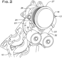
FIG. 2 is a bottom perspective view of the bracket. -
FIG. 1 shows the right side, with reference to an operator, of a lift truck engine block. The illustrated engine is used in Mitsubishi manufactured Caterpillar lift trucks of series GC35K to 55K. Theengine block 10 on the right side is manufactured with a plurality of 3 internally threaded bosses that receivebolts 11, two of which are seen inFIG. 1 . Similarly, at a front of theengine 10 are two internally threaded bosses that receivebolts 12. - A combined motor mount and refrigerant
compressor mount bracket 13 is fixed to theengine block 10 with thebolts bracket 13 is fabricated as a steel weldment but can be a steel or other suitable metal casting. Various plates of thebracket 13 can be 3/8 inch thick. Abase plate 14 of the bracket abuts theblock 10 and has holes aligned with internally threaded bosses for reception ofsuitable bolts 11. - Two
plates plate 14 extend to anangled plate 18. Theangled plate 18 has anaperture 19 to receive a central bolt of a conventional elastomeric motor mount. Elastomeric pads of the motor mount are assembled, one at each face of theangle plate 18, as is conventional. A lower one of the pads engages a part of the frame of the lift truck to bear the weight of the engine and torque forces. - The
plate 18, in the illustrated design, extends to a location forward of theengine block 10. Theplate 18 is stiffened withwelded gussets gussets 22 extends to the front of theengine block 10 where it is secured with thebolts 12. Twoparallel gussets plate 18 and provide surfaces and threaded holes for receiving mounting flanges of acompressor 26 andcorresponding bolts 24. Surfaces of thegussets compressor pulley 27 with a crankshaft pulley so that they are in a common plane. Central holes incylindrical bosses 31 on thefrontward gusset 23 provide mounting centers foridler pulleys 32 that guide a serpentine belt around at least 1/2 of the compressor pulley circumference.
Claims (4)
- A bracket for mounting on the engine of a lift truck, the bracket having a plate to be bolted to the side of the block with bolts through holes in the plate configured to be aligned with threaded holes on the side of the engine block, at least one extension from the plate to a foot with an aperture, the aperture being arranged to receive the bolt associated with an elastomeric motor mount, the foot having an extension forwardly of the engine block, the foot extension having surfaces, supported by said at least one extension, in a plane perpendicular to the crankshaft of the engine, the surfaces having apertures for receiving bolts that align with mounting holes on a housing of the compressor.
- A bracket as set forth in claim 1, wherein a mounting element rigid with the plate includes holes for receiving mounting bolts at the front of the engine block.
- A bracket as set forth in claim 1 or claim 2,
wherein said at least one extension and another extension are situated at opposite ends of the plate. - A bracket as set forth in any preceding claim,
wherein said at least one extension is in a generally vertical plane when the plate is bolted to the engine block and the engine is in an operational orientation.
Applications Claiming Priority (1)
| Application Number | Priority Date | Filing Date | Title |
|---|---|---|---|
| US18/145,039 US12071015B2 (en) | 2022-12-22 | 2022-12-22 | Combined motor and compressor mount for lift truck |
Publications (2)
| Publication Number | Publication Date |
|---|---|
| EP4390085A2 true EP4390085A2 (en) | 2024-06-26 |
| EP4390085A3 EP4390085A3 (en) | 2024-07-03 |
Family
ID=89430559
Family Applications (1)
| Application Number | Title | Priority Date | Filing Date |
|---|---|---|---|
| EP23218133.9A Withdrawn EP4390085A3 (en) | 2022-12-22 | 2023-12-19 | Combined motor and compressor mount for lift truck |
Country Status (4)
| Country | Link |
|---|---|
| US (1) | US12071015B2 (en) |
| EP (1) | EP4390085A3 (en) |
| JP (1) | JP2024091486A (en) |
| CA (1) | CA3223337A1 (en) |
Family Cites Families (25)
| Publication number | Priority date | Publication date | Assignee | Title |
|---|---|---|---|---|
| US1743612A (en) * | 1928-04-04 | 1930-01-14 | Chrysler Corp | Motor mounting |
| BE789326A (en) * | 1971-09-27 | 1973-03-27 | Towmotor Corp | Mount for electric propulsion motor and for drive means. |
| US4593786A (en) * | 1982-05-03 | 1986-06-10 | John Tate | Self-contained power supply and support therefor |
| JP2003104069A (en) * | 2001-09-28 | 2003-04-09 | Suzuki Motor Corp | Mounting device for V-type engine |
| CN201520624U (en) | 2009-10-23 | 2010-07-07 | 安徽合力股份有限公司 | Mounting mechanism of air conditioner compressor of forklift truck |
| JP5616194B2 (en) * | 2010-01-14 | 2014-10-29 | 株式会社クボタ | Engine with exhaust treatment device |
| JP2011196194A (en) * | 2010-03-17 | 2011-10-06 | Yanmar Co Ltd | Exhaust emission control device |
| FR2980742A3 (en) * | 2011-10-03 | 2013-04-05 | Renault Sas | SUPPORT OF MOTOR BLOCK |
| US9752479B2 (en) * | 2012-07-05 | 2017-09-05 | Yanmar Co., Ltd. | Engine apparatus |
| JP5882158B2 (en) * | 2012-07-26 | 2016-03-09 | ヤンマー株式会社 | Engine equipment |
| CN105051335B (en) * | 2013-03-29 | 2018-01-30 | 洋马株式会社 | Waste gas cleaning system |
| JP6120689B2 (en) * | 2013-06-14 | 2017-04-26 | ヤンマー株式会社 | Tractor |
| CN203383902U (en) | 2013-06-29 | 2014-01-08 | 广西玉柴机器股份有限公司 | Air conditioner compressor auxiliary support |
| FR3038265B1 (en) * | 2015-07-01 | 2017-07-28 | Peugeot Citroen Automobiles Sa | MOTOR PROPELLER GROUP WITH PARTIAL INTEGRATION OF AN AIR INJECTION SYSTEM IN A MOTOR SUPPORT |
| JP6518168B2 (en) * | 2015-08-26 | 2019-05-22 | 本田技研工業株式会社 | Motor mounting structure |
| DE102016000670B3 (en) * | 2016-01-22 | 2017-01-12 | Audi Ag | Subframe for a two-lane motor vehicle |
| CN107956579B (en) | 2017-11-02 | 2022-04-01 | 广西玉柴机器股份有限公司 | Multifunctional air-conditioning compressor integrated bracket |
| DE102017220095B4 (en) * | 2017-11-10 | 2026-03-19 | Volkswagen Aktiengesellschaft | Front axle subframe with a bearing for a drive unit |
| US10625590B1 (en) * | 2019-01-28 | 2020-04-21 | Caterpillar Inc. | Integrated mounting structure for an engine |
| CN110131133A (en) | 2019-05-31 | 2019-08-16 | 安徽合力股份有限公司 | An adjustable air conditioner compressor installation structure for a forklift |
| KR102644582B1 (en) * | 2019-10-15 | 2024-03-06 | 현대자동차주식회사 | Mounting system for powertrain of vehicle |
| US11078823B1 (en) * | 2020-02-05 | 2021-08-03 | GM Global Technology Operations LLC | Engine thermal management device assembly having an engine accessory mounting bracket |
| WO2021254720A1 (en) * | 2020-06-17 | 2021-12-23 | Sew-Eurodrive Gmbh & Co. Kg | Drive, comprising a gear mechanism driven by an electric motor |
| GB2598990B (en) * | 2020-08-06 | 2022-11-30 | Deere & Co | Utility vehicle automatic transmission powertrain mounting |
| MX2023007856A (en) * | 2021-01-12 | 2023-07-07 | Hendrickson Usa Llc | Wishbone-shaped linkage and modular bushing assembly and suspension systems incorporating the same. |
-
2022
- 2022-12-22 US US18/145,039 patent/US12071015B2/en active Active
-
2023
- 2023-12-05 JP JP2023205716A patent/JP2024091486A/en active Pending
- 2023-12-15 CA CA3223337A patent/CA3223337A1/en active Pending
- 2023-12-19 EP EP23218133.9A patent/EP4390085A3/en not_active Withdrawn
Also Published As
| Publication number | Publication date |
|---|---|
| US12071015B2 (en) | 2024-08-27 |
| EP4390085A3 (en) | 2024-07-03 |
| CA3223337A1 (en) | 2024-06-22 |
| JP2024091486A (en) | 2024-07-04 |
| US20240208320A1 (en) | 2024-06-27 |
Similar Documents
| Publication | Publication Date | Title |
|---|---|---|
| US4403648A (en) | Engine radiator support and guard assembly | |
| US6695087B2 (en) | Snowmobile engine mount | |
| US4600367A (en) | Refrigerant compressor for automobile air-conditioning system | |
| US9534615B1 (en) | Hydraulic pump and motor module for use in a vehicle | |
| US20080060867A1 (en) | Power unit for a vehicle | |
| US4825815A (en) | Pivotal cooling unit | |
| US20230234437A1 (en) | Apparatus for mounting a front differential to a vehicle chassis | |
| EP0493877B1 (en) | Bearing support | |
| EP1260402A1 (en) | Powertrain module for zero turn radius vehicle | |
| EP4390085A2 (en) | Combined motor and compressor mount for lift truck | |
| US5094309A (en) | Accessory for mounting an engine driven component to a vehicle frame | |
| GB2105833A (en) | Transport refrigeration unit with removable power pack frame | |
| EP0514014B1 (en) | Transport refrigeration system | |
| US4597746A (en) | Fan drive system for transverse engine | |
| GB2598990A (en) | Utility vehicle automatic transmission powertrain mounting | |
| US6585035B2 (en) | Transmission for driving a radial fan of a vehicle cooling unit | |
| US3181825A (en) | Generator pump and bracket assembly | |
| US11772476B2 (en) | Utility vehicle automatic transmission powertrain mounting | |
| US4506747A (en) | Axle tube and hydraulic motor housing mounting arrangement | |
| EP4433694B1 (en) | Arrangement of auxiliary equipment in the engine bay of a commercial vehicle | |
| US5465804A (en) | Combination of a power steering pump and air conditioning compressor in an automotive vehicle | |
| US7442137B2 (en) | Eccentric mounting and adjustment system for belt driven devices | |
| CN100471711C (en) | Drive system of bus cooling fan | |
| EP1636512B1 (en) | Engine-driven vehicle | |
| CN210343501U (en) | Integral air condition compressor support |
Legal Events
| Date | Code | Title | Description |
|---|---|---|---|
| PUAI | Public reference made under article 153(3) epc to a published international application that has entered the european phase |
Free format text: ORIGINAL CODE: 0009012 |
|
| STAA | Information on the status of an ep patent application or granted ep patent |
Free format text: STATUS: THE APPLICATION HAS BEEN PUBLISHED |
|
| PUAL | Search report despatched |
Free format text: ORIGINAL CODE: 0009013 |
|
| AK | Designated contracting states |
Kind code of ref document: A2 Designated state(s): AL AT BE BG CH CY CZ DE DK EE ES FI FR GB GR HR HU IE IS IT LI LT LU LV MC ME MK MT NL NO PL PT RO RS SE SI SK SM TR |
|
| AK | Designated contracting states |
Kind code of ref document: A3 Designated state(s): AL AT BE BG CH CY CZ DE DK EE ES FI FR GB GR HR HU IE IS IT LI LT LU LV MC ME MK MT NL NO PL PT RO RS SE SI SK SM TR |
|
| RIC1 | Information provided on ipc code assigned before grant |
Ipc: B66F 9/075 20060101ALN20240528BHEP Ipc: F02F 7/00 20060101ALI20240528BHEP Ipc: B60K 25/00 20060101ALI20240528BHEP Ipc: F02B 67/06 20060101AFI20240528BHEP |
|
| P01 | Opt-out of the competence of the unified patent court (upc) registered |
Free format text: CASE NUMBER: APP_43964/2024 Effective date: 20240729 |
|
| STAA | Information on the status of an ep patent application or granted ep patent |
Free format text: STATUS: REQUEST FOR EXAMINATION WAS MADE |
|
| STAA | Information on the status of an ep patent application or granted ep patent |
Free format text: STATUS: THE APPLICATION HAS BEEN WITHDRAWN |
|
| 17P | Request for examination filed |
Effective date: 20241030 |
|
| RBV | Designated contracting states (corrected) |
Designated state(s): AL AT BE BG CH CY CZ DE DK EE ES FI FR GB GR HR HU IE IS IT LI LT LU LV MC ME MK MT NL NO PL PT RO RS SE SI SK SM TR |
|
| 18W | Application withdrawn |
Effective date: 20241113 |