EP4390053A2 - Verfahren zur injektion von flüssigkeiten in ein bohrloch - Google Patents
Verfahren zur injektion von flüssigkeiten in ein bohrloch Download PDFInfo
- Publication number
- EP4390053A2 EP4390053A2 EP23307314.7A EP23307314A EP4390053A2 EP 4390053 A2 EP4390053 A2 EP 4390053A2 EP 23307314 A EP23307314 A EP 23307314A EP 4390053 A2 EP4390053 A2 EP 4390053A2
- Authority
- EP
- European Patent Office
- Prior art keywords
- fluid
- downhole apparatus
- wellbore
- volume
- downhole
- Prior art date
- Legal status (The legal status is an assumption and is not a legal conclusion. Google has not performed a legal analysis and makes no representation as to the accuracy of the status listed.)
- Pending
Links
Images



Classifications
-
- E—FIXED CONSTRUCTIONS
- E21—EARTH OR ROCK DRILLING; MINING
- E21B—EARTH OR ROCK DRILLING; OBTAINING OIL, GAS, WATER, SOLUBLE OR MELTABLE MATERIALS OR A SLURRY OF MINERALS FROM WELLS
- E21B33/00—Sealing or packing boreholes or wells
- E21B33/10—Sealing or packing boreholes or wells in the borehole
- E21B33/12—Packers; Plugs
- E21B33/124—Units with longitudinally-spaced plugs for isolating the intermediate space
-
- E—FIXED CONSTRUCTIONS
- E21—EARTH OR ROCK DRILLING; MINING
- E21B—EARTH OR ROCK DRILLING; OBTAINING OIL, GAS, WATER, SOLUBLE OR MELTABLE MATERIALS OR A SLURRY OF MINERALS FROM WELLS
- E21B17/00—Drilling rods or pipes; Flexible drill strings; Kellies; Drill collars; Sucker rods; Cables; Casings; Tubings
- E21B17/02—Couplings; joints
- E21B17/021—Devices for subsurface connecting or disconnecting by rotation
-
- E—FIXED CONSTRUCTIONS
- E21—EARTH OR ROCK DRILLING; MINING
- E21B—EARTH OR ROCK DRILLING; OBTAINING OIL, GAS, WATER, SOLUBLE OR MELTABLE MATERIALS OR A SLURRY OF MINERALS FROM WELLS
- E21B17/00—Drilling rods or pipes; Flexible drill strings; Kellies; Drill collars; Sucker rods; Cables; Casings; Tubings
- E21B17/02—Couplings; joints
- E21B17/023—Arrangements for connecting cables or wirelines to downhole devices
-
- E—FIXED CONSTRUCTIONS
- E21—EARTH OR ROCK DRILLING; MINING
- E21B—EARTH OR ROCK DRILLING; OBTAINING OIL, GAS, WATER, SOLUBLE OR MELTABLE MATERIALS OR A SLURRY OF MINERALS FROM WELLS
- E21B23/00—Apparatus for displacing, setting, locking, releasing or removing tools, packers or the like in boreholes or wells
- E21B23/06—Apparatus for displacing, setting, locking, releasing or removing tools, packers or the like in boreholes or wells for setting packers
-
- E—FIXED CONSTRUCTIONS
- E21—EARTH OR ROCK DRILLING; MINING
- E21B—EARTH OR ROCK DRILLING; OBTAINING OIL, GAS, WATER, SOLUBLE OR MELTABLE MATERIALS OR A SLURRY OF MINERALS FROM WELLS
- E21B33/00—Sealing or packing boreholes or wells
- E21B33/10—Sealing or packing boreholes or wells in the borehole
- E21B33/12—Packers; Plugs
- E21B33/122—Multiple string packers
-
- E—FIXED CONSTRUCTIONS
- E21—EARTH OR ROCK DRILLING; MINING
- E21B—EARTH OR ROCK DRILLING; OBTAINING OIL, GAS, WATER, SOLUBLE OR MELTABLE MATERIALS OR A SLURRY OF MINERALS FROM WELLS
- E21B47/00—Survey of boreholes or wells
- E21B47/10—Locating fluid leaks, intrusions or movements
- E21B47/11—Locating fluid leaks, intrusions or movements using tracers; using radioactivity
-
- E—FIXED CONSTRUCTIONS
- E21—EARTH OR ROCK DRILLING; MINING
- E21B—EARTH OR ROCK DRILLING; OBTAINING OIL, GAS, WATER, SOLUBLE OR MELTABLE MATERIALS OR A SLURRY OF MINERALS FROM WELLS
- E21B49/00—Testing the nature of borehole walls; Formation testing; Methods or apparatus for obtaining samples of soil or well fluids, specially adapted to earth drilling or wells
- E21B49/008—Testing the nature of borehole walls; Formation testing; Methods or apparatus for obtaining samples of soil or well fluids, specially adapted to earth drilling or wells by injection test; by analysing pressure variations in an injection or production test, e.g. for estimating the skin factor
-
- E—FIXED CONSTRUCTIONS
- E21—EARTH OR ROCK DRILLING; MINING
- E21B—EARTH OR ROCK DRILLING; OBTAINING OIL, GAS, WATER, SOLUBLE OR MELTABLE MATERIALS OR A SLURRY OF MINERALS FROM WELLS
- E21B49/00—Testing the nature of borehole walls; Formation testing; Methods or apparatus for obtaining samples of soil or well fluids, specially adapted to earth drilling or wells
- E21B49/08—Obtaining fluid samples or testing fluids, in boreholes or wells
- E21B49/081—Obtaining fluid samples or testing fluids, in boreholes or wells with down-hole means for trapping a fluid sample
- E21B49/083—Samplers adapted to be lowered into or retrieved from a landing nipple, e.g. for testing a well without removing the drill string
Definitions
- Embodiments described generally relate to injection of fluids into a wellbore. More particularly, such embodiments relate to processes for injection of fluids into a wellbore via a downhole apparatus. Embodiments also relate to a process to enable flushing a near wellbore region with a fluid, thereby displacing native fluids so that evaluation of the nearby geological stratum can be tested. This displacement of the native fluids produces both a sweeping effect and a residual saturation for the geological stratum that may be measured. Embodiments also provide for circulation of fluid down in a wellbore with injection in the formation, rather than the wellbore.
- Proper testing of wellbore environments can provide many advantages to engineers and operators. Some of the most important information can be derived from injection processes for some types of wellbores. In some instances, geological stratum can allow injection of fluids such as gases, liquids, acids, caustics, and other materials into the formation. The injection of such materials into a wellbore can facilitate certain advantages in the downhole environment.
- an injection well can be located near a production well that is used to recover hydrocarbons. After a certain amount of time, the production well can start to lose economic viability as the pressure head within the wellbore of the production well decreases. For one to be able to recover a greater quantity of hydrocarbons from the production well, artificial lift procedures can be used to increase the amount of recoverable hydrocarbons from areas adjacent to the production well. While these procedures may have certain advantages, there are some limitations for such activities. For example, production wells can only provide a certain amount of lift within a wellbore. After this amount of lift is achieved, any remaining hydrocarbons within the areas around the production well will not be recovered, limiting the overall economic viability of the wellbore.
- an injection well is created where the materials previously mentioned can be injected into the geological stratum thereby pushing hydrocarbons from the injection well toward the production well. This gradual forcing of hydrocarbons from the injection well to the production well can greatly increase the quantity of hydrocarbons recovered in the production well.
- Conventional techniques used to determine injectivity of a geological stratum are often haphazard and rudimentary.
- the process can include positioning a downhole apparatus on a drill pipe.
- the process can also include placing the downhole apparatus at a desired station depth within a wellbore.
- the process can also include attaching a cable to the downhole apparatus from an up-hole environment.
- the process can also include setting at least one packer to seal a space between at least a portion of the downhole apparatus and an inner surface of the wellbore.
- the process can also include introducing a fluid to the downhole apparatus through the drill pipe.
- the process can also include using a pump from the downhole apparatus or a pump located at a surface of the earth to inject at least a portion of the fluid from the downhole apparatus into a geological stratum at the desired station depth.
- the process can include positioning a downhole apparatus on a drill pipe.
- the process can also include placing the downhole apparatus at a desired station depth within a wellbore.
- the process can also include attaching a cable to the downhole apparatus from an up-hole environment.
- the process can also include setting two packers longitudinally spaced apart from one another on the downhole apparatus to provide a sealed volume between the downhole apparatus and an inner surface of the wellbore.
- the sealed volume can include a drilling mud disposed therein.
- the process can also include introducing a first fluid to the downhole apparatus through the drill pipe.
- the process can also include using a pump from the downhole apparatus or a pump located at a surface of the earth to inject at least a portion of the first fluid from the downhole apparatus into the sealed volume.
- the process can also include flowing at least a portion of the drilling mud from the sealed volume into the downhole apparatus.
- the process can also include introducing the at least a portion of the drilling mud into the wellbore at a location located between a surface of the earth and the packer closest to the surface of the earth such that the sealed volume contains less drilling mud disposed therein.
- the process can include a downhole apparatus on a drill pipe.
- the process can also include placing the downhole apparatus at a desired station depth within a wellbore.
- the process can also include attaching a cable to the downhole apparatus from an up-hole environment.
- the process can also include setting two packers longitudinally spaced apart from one another on the downhole apparatus to provide a sealed volume between the downhole apparatus and an inner surface of the wellbore.
- the sealed volume can include a drilling mud, a formation fluid, or a mixture thereof disposed therein.
- the process can also include using a pump from the downhole apparatus to inject at least a portion of a first fluid from the downhole apparatus into the sealed volume.
- the first fluid can be obtained from a chamber of the downhole apparatus that contains the first fluid.
- the process can also include flowing at least a portion of the drilling mud, the formation fluid, or the mixture thereof from the sealed volume into the downhole apparatus.
- the process can also include introducing the at least a portion of the drilling mud, the formation fluid, or the mixture thereof into the wellbore at a location located between a surface of the earth and the packer closest to the surface of the earth such that the sealed volume contains less of the drilling mud, the formation fluid, or the mixture thereof disposed therein.
- a process may comprise placing the downhole apparatus at a desired station depth within a wellbore.
- the process may also comprise attaching a cable to the downhole apparatus from an up-hole environment.
- the process may also comprise performing a first test of a saturation level of geological stratum at the desired station depth.
- the process may further comprise setting a dual packer to seal a space between at least a portion of the downhole apparatus and an inner surface of the wellbore.
- the process may further comprise introducing a fluid to the downhole apparatus through the drill pipe,
- the process may also comprise circulating at least a portion of the fluid through a first line from a circulating sub to a bottom outlet.
- the process may also comprise creating a suction in a dual packer interval from an upper inlet into a secondary flowline.
- the process may further comprise replacing at least a portion of fluid from the dual packer interval with the portion of the circulated fluid.
- the process may also comprise using a pump to inject at least a portion of the fluid from the downhole apparatus into a geological stratum at the desired station depth.
- the process may also comprise performing a second test of the saturation level of geological stratum at the desired depth.
- the process may also comprise determining a change in the saturation level from the first test to the second test.
- a process in another embodiment, may comprise positioning a downhole apparatus on a drill pipe.
- the process may further comprise placing the downhole apparatus at a desired station depth within a wellbore.
- the process may further comprise attaching a cable to the downhole apparatus from an up-hole environment.
- the process may further comprise performing a first geological stratum test at the desired station depth.
- the process may further comprise setting a dual packer to seal a space between at least a portion of the downhole apparatus and an inner surface of the wellbore.
- the process may further comprise introducing a fluid to the downhole apparatus through the drill pipe, wherein the fluid includes both a drill fluid and one of a fresh water volume and a brine volume, the one of the fresh water volume and the brine volume in a pill.
- the process may also comprise circulating at least a portion of the fresh water volume and the brine volume through a first line from a circulating sub to a bottom outlet.
- the process may also comprise creating a suction in a dual packer interval from an upper inlet into a secondary flowline.
- the process may also comprise replacing at least a portion of fluid from the dual packer interval with the portion of fresh water volume and brine volume.
- the process may also comprise using a pump to inject at least a portion of the fluid from the downhole apparatus into a geological stratum at the desired station depth.
- the process may also comprise performing a second geological stratum test at the desired station depth and determining a change from the first test to the second test.
- first, second, third, etc. may be used herein to describe various elements, components, regions, layers, and/or sections, these elements, components, regions, layers, and/or sections should not be limited by these terms. These terms may be only used to distinguish one element, component, region, layer or section from another region, layer, or section. Terms such as “first”, “second” and other numerical terms, when used herein, do not imply a sequence or order unless clearly indicated by the context. Thus, a first element, component, region, layer, or section discussed herein could be termed a second element, component, region, layer, or section without departing from the teachings of the example embodiments.
- FIG. 1 depicts an illustrative downhole assembly 100 that includes an illustrative downhole apparatus 103 configured to carry out a first operation, according to one or more embodiments.
- the downhole assembly 100 can include, but is not limited to, the downhole apparatus 103, a drill pipe 105, and a side entry sub 109.
- the downhole apparatus 103 can be positioned or otherwise connected to a first end of the drill pipe 105 via a slip joint or other connection 107.
- the side entry sub 109 can be connected to a second end of the drill pipe 105.
- the drill pipe 105 can include any number of sections of pipe connected together with the number of connected pipes configured to locate the downhole apparatus 103 at a desired station depth within a wellbore.
- the downhole apparatus 103 can be a wireline tool configured to connect to the drill pipe 105.
- a suitable wireline tool can include the Ora intelligent wireline formation testing tool available from Schlumberger.
- a wireline cable 111 can be fed into the side entry sub 109 and into a flow path of the drill pipe 105 and can be pumped or otherwise conveyed down and connected, e.g., via a wet connector, to the downhole apparatus 103.
- the wireline cable 111 can, among other capabilities, be configured to transmit power to the downhole apparatus 103 and/or transmit and receive data to and from the downhole apparatus 103.
- the downhole assembly 100 after being located within the wellbore at a first desired station depth and carrying out one or more operations, can be moved further into the wellbore to move the downhole assembly 100 to a second station depth and so on by connecting one or more additional sections of pipe while the additional length of wireline cable 111 can remain outside the additional section(s) of pipe.
- the downhole apparatus 103 can include a circulation sub 113, at least one pump, two are shown, 117 and 119, and at least one packer, two are shown, 121, 123.
- the first and second packers 121, 123 can be longitudinally spaced apart from one another on the downhole apparatus 103 such that when the downhole apparatus 103 is located within the wellbore and the packers 121, 123 have been set, the set packers 121, 123 can provide a sealed volume therebetween.
- the downhole apparatus 103 can also include a chamber 118 that can be configured to store fluid that can be injected into the wellbore via the downhole tool 103.
- the downhole apparatus 103 can also include a fluid analyzer 115. In some embodiments, the downhole apparatus 103 can also include a power module 116 configured to provide power to the downhole apparatus 103. In some embodiments, the downhole apparatus 103 can also include a packer valve block and electronics assembly 124 configured to move the packers 121, 123 between a closed or unset position and an open or set position.
- Two or more flow paths, two are shown, 125, 127 can be disposed within the downhole apparatus 103.
- the first pump 117 can be configured to convey a fluid, e.g., a gas and/or a liquid, through the first flow path 125 and the second pump 119 can be configured to convey a fluid, e.g., a gas and/or a liquid, through the second flow path 127.
- the first and second pumps 117, 119 can be bi-directional pumps that can convey fluids in either direction through the first and second flow paths 125, 127, respectively.
- the first pump 117 and/or the second pump 119 can be placed in a bypass mode and one or more pumps located at a surface of the earth can be used to convey the fluid through the first flow path 125 and/or the second flow path 127.
- one of the first and second pumps 117, 119 can be used to convey the fluid through one of the first flow path 125 and the second flow path 127 and a pump located at the surface of the earth can be used to convey the fluid through the other of the first flow path 125 and the second flow path 127.
- the direction a fluid can be conveyed through the first and second flow paths 125, 127 can depend on the operation being carried out with the downhole apparatus 103. It should be understood that the first flow path 125 and/or the second flow path 127 can include a single flow path/flow line or two or more separate flow paths/flow lines that can convey a fluid therethrough. It should also be understood that the fluid(s) that can be conveyed through the first flow path 125 and/or the second flow path 127 can include solids that can be slurried, suspended, dispersed, or otherwise disposed within the fluid(s).
- the fluid when a fluid is desired to be introduced into the first flow path 125, the fluid can be introduced via the drill pipe 105 to the downhole apparatus 103. In some embodiments, the fluid can flow through a flow path defined by the drill pipe 105. In other embodiments, the fluid can flow through a coiled tube disposed within the flow path defined by the drill pipe 105. In some embodiments, the fluid analyzer 115 can be used to detect the presence of the fluid within the downhole apparatus 103. The fluid analyzer 115 can detect any one or more of a number of properties of the fluid.
- the fluid analyzer 115 can include a spectrometer, fluorescence, resistivity, viscosity, and/or density sensors, pressure and temperature gauges, or any combination thereof.
- the fluid analyzer 115 can include a spectrometer, fluorescence, resistivity, viscosity, and/or density sensors, pressure and temperature gauges, or any combination thereof.
- the fluid can be introduced from the downhole apparatus 103 and into a wellbore the downhole apparatus can be located within.
- the fluid when the fluid is desired to be introduced into the first flow path 125, the fluid can be introduced via the chamber 118 of the downhole apparatus 103.
- the fluid can be introduced from the downhole apparatus 103 into the wellbore after the at least one packer 121 and/or 123 has been set without the need to detect the presence of the fluid with the fluid analyzer 115.
- the first flow path 125 can be configured to convey a fluid (indicated by arrow 128) from the drill pipe 105 and out a first port 129 located between the first and second packers 121, 123 and the second flow path 127 can be configured to receive a fluid (indicated by arrow 130) from outside the downhole apparatus 103 through a second port 131 located between the first and second packers 121, 123 and convey the fluid 130 to the circulation sub 113.
- the first flow path 125 can be in fluid communication with and configured to receive the fluid from the drill pipe 105 and the second flow path 127 can be in fluid communication with and configured to direct the fluid 130 into the circulation sub113.
- the first flow path 125 can be in fluid communication with and configured to receive the fluid from the chamber 118 and the second flow path 127 can be in fluid communication with and configured to direct the fluid 130 into the circulation sub 113.
- the circulation sub 113 can transfer the fluid 130 through one or more ports 133 to outside the downhole apparatus 103 above the first packer 121.
- the fluid 130 conveyed from outside the downhole apparatus 103 can be or can include, but is not limited to, drilling mud, formation fluid, or any other fluid that can be disposed within a wellbore.
- the fluid 128 that can be conveyed out the first port 129 can be a gas, a liquid, or a mixture thereof.
- the fluid can include one or more solids, e.g., a proppant, that can be slurried, suspended, dispersed, or otherwise disposed within the fluid(s).
- Illustrative liquids can be or can include, but are not limited to, water, one or more acids, one or more emulsifiers, one or more hydrocarbons, one or more surfactants, one or more tracers, or any mixture thereof.
- Illustrative gases can be or can include, but are not limited to, carbon monoxide, carbon dioxide, nitrogen, one or more hydrocarbons, or any mixture thereof.
- Suitable tracers can include any material that can be used to measure fluid movement in a well such as a bead tracer and a radioactive tracer.
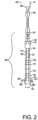
- FIG. 2 depicts the down hole assembly 100 shown in FIG. 1 with the downhole apparatus 103 configured to carry out a second operation, according to one or more embodiments.
- both the first flow path 125 and the second flow path 127 can be configured to convey a fluid (indicated by arrows 228) from the drill pipe 105 and out the first and second ports 129, 131, respectively, located between the first and second packers 121, 123.
- the second flow path 127 can be configured to be in fluid communication with the drill pipe 105 and not in fluid communication with the circulation sub 113, e.g., by actuating valve(s) to place the second flow path 127 into fluid communication with the drill pipe 105.
- just the first flow path 125 can be configured to convey the fluid 228 from the drill pipe 105 and out the first port 129, with the second flow path 127 being isolated from the wellbore environment by closing a valve or other isolation device.
- the one or more ports 133 of the circulation sub 113 can be fluidly isolated from the wellbore by closing one or more valves or other isolation device.
- the first flow path 125 or the first and second flow paths 125, 127 can be configured to convey the fluid received from the drill pipe 105 or the optional coiled tubing that can be disposed within the drill pipe 105 from the down hole apparatus 103 and into the wellbore such that at least a portion of the fluid 228 can be injected from the downhole apparatus 103 into a geological stratum when the at least one packer 121 and/or 123 is in a set configuration with the downhole apparatus 103 located at a desired station depth within the wellbore.
- the downhole apparatus 103 can be configured to carry out the first operation shown in FIG. 1 and then reconfigured while maintained within the wellbore to carry out the second operation.
- the downhole apparatus 103 can be configured to carry out multiple first operations, multiple second operations, or a combination of multiple first and second operations in any order or sequence.
- water or other fluid can be circulated as in the first operation between each second operation when two or more second operations are carried out at a desired station depth.
- two or more second operations can be carried out to inject one or more fluids into a geological stratum at the desired station depth without the first operation being carried out between the two second operations.
- the downhole tool 103 can be used to carry out the first operation that can be followed by one or more second operations.
- a composition of the fluid can be the same or different between any two operations that follow one another.
- the downhole apparatus 103 can be used to carry out the first operation to introduce a first fluid, e.g., water, and reconfigured to carry out the second operation to introduce a second fluid, e.g., carbon dioxide, that can be followed by one or more additional second operations to introduce a third, fourth, etc. fluid, e.g., an acid, a surfactant, a caustic, water, etc.
- the quantity or volume of fluid 128 introduced via port 129 from the downhole apparatus 103 and/or the quantity or volume of fluid 228 introduced via port 129 or ports 129 and 131 from the downhole apparatus 103 can be any desired amount.
- the amount of liquid can be at least 23 L, at least 25 L, at least 30 L, at least 40 L, at least 50 L, at least 75 L, at least 100 L, at least 125 L, or at least 150 L.
- the amount or volume of liquid can be at least the volume within the isolated or sealed volume provided via the set packers 121, 123.
- the amount of liquid that can be introduced per day can range from about 8 L to about 17,200 L.
- the fluid 128, 228 is a gas quantity or volume of gas can be at least 10 m 3 , at least 20 m 3 , at least 30 m 3 , at least 40 m 3 , at least 50 m 3 , or at least 75 m 3 at standard temperature and pressure.
- about 25 m 3 to about 35 m 3 e.g., about 31 m 3
- carbon dioxide can be injected via port 129 and/or ports 129, 131.
- the fluid can be introduced from the downhole apparatus 103 under any desired pressure.
- the fluid can be introduced via port 129 or ports 129 and 131 at a pressure that can be between a formation pressure and a pressure within the wellbore.
- the volume of fluid introduced via port 129 or ports 129, 131 can be introduced at any desired flow rate.
- a period of time from starting the introduction of the fluid until the volume of fluid has been introduced and introduction has stopped can be in a range from 30 seconds, 1 minute, 5 minutes, 10 minutes, or 20 minutes to 30 minutes 45 minutes 1 hours, 2 hours, 5 hours, 10 hours, 24 hours, or longer.
- FIG. 3 depicts a cross-section of a wellbore 305 that includes another illustrative downhole assembly 310 that includes another downhole apparatus 315 disposed therein, according to one or more embodiments.
- the downhole apparatus 315 can be the downhole apparatus 103 described above with reference to FIGS. 1 and 2 .
- the downhole apparatus 315 can be positioned on a drill pipe 316 and placed at a desired station depth within the wellbore 305.
- a cable 308 can be attached to the downhole apparatus 315 from an up-hole environment.
- an upper portion of the wellbore 305 can include a casing 306 and a lower portion of the wellbore 305 can be uncased and open to a borehole wall 307.
- the downhole apparatus 315 can include at least one packer, two are shown, 317, 319.
- the first and second packers 317, 319 can be set to provide a sealed space or volume 320 between at least a portion of the downhole apparatus 315 and the borehole wall 307.
- a fluid 321 can be injected from the downhole apparatus 315 into a geological stratum 330.
- the fluid 321 can be introduced from a fluid source 325 via line 326 into the drill pipe 316 (or optional coiled tubing that can be disposed within the drill pipe 316) and introduced to the downhole apparatus 315.
- a pump 327 located on a surface of the earth 329 can be used to introduce the fluid 321 into the drill pipe 316 (or the optional coiled tubing).
- the pump 327 can be a rig pump.
- one or more pumps in the downhole apparatus 315 can be used to introduce the fluid 321 from the downhole apparatus 315 and into the sealed volume 320 and the fluid 321 can flow into the geological stratum 330.
- the pump 327 can be used to introduce the fluid 321 into the sealed volume 320 and the fluid 321 can flow into the geological stratum 330.
- the downhole apparatus 315 can use a fluid analyzer to detect and confirm the fluid 321 has been introduced thereto via the drill pipe 308 and/or the optional coiled tubing.
- the downhole apparatus 315 can be configured to operate in the first configuration described above with reference to FIG. 1 such that the fluid 321 can be introduced into the sealed volume 320 that can cause a downhole fluid, e.g., drilling mud, within the sealed volume 320 to flow into the downhole apparatus 315 and back into the wellbore 305 above the first packer 317.
- the injection of the fluid 321 into the sealed volume 320 can be controlled through actuation of downhole pumps in the downhole apparatus 315 and/or the pump 327 located on the surface 329.
- one process can include only inj ection of a liquid with the downhole apparatus.
- one process can include only injection of a gas.
- the injection of the liquid and/or the gas can occur through coiled tubing disposed within the drill pipe.
- about 31 cubic meters of carbon dioxide can be injected. After injection of the liquid or the gas, equilibrium can be reestablished between the drill pipe and the wellbore.
- the apparatus and processes disclosed herein can allow for injection of fluids via a drill pipe and/or coiled tubing disposed within the drill pipe to downhole environments from a downhole apparatus attached to the drill pipe.
- Embodiments provide for using downhole pumps and/or pumps, e.g., one or more rig pumps, located on the surface of the earth to create the injection pressure into the geological stratum. Injection can occur at different stations or elevations within the wellbore. Injection can also include different types of fluids, including liquids, gases, and/or combinations of liquids and gases. Aspects of the disclosure provide for an economical process to inject such fluids.
- the packers 317, 319 maintaining the sealed volume 320 can be unset and an equilibrium between the drill pipe 308 and the wellbore can be established.
- the equilibrium can be established through a control device, such as a series of valves, in one non-limiting embodiment.
- a new station depth can be selected, the downhole assembly 310 can be moved to the new station depth, and a desired operation can be carried out by the downhole apparatus 315 or the downhole assembly 310 can be removed from the wellbore 305.
- FIG. 4 depicts an illustrative process 500 for injecting a fluid into a geological stratum, according to one or more embodiments.
- the process 500 can include running a downhole apparatus, at 502, on a drill pipe to a station depth. As will be understood, the process 500 may be accomplished by any of the embodiments disclosed in FIGS. 1 to 3 .
- the process can continue with latching a cable to establish contact between the downhole apparatus and the up-hole environment.
- the process can include setting one or more packers to seal an interval between the downhole apparatus and a wellbore wall.
- the process can further include introducing a first fluid, e.g., water, at the depth station.
- a first fluid e.g., water
- the first fluid can be introduced via the drill pipe or coiled tubing disposed within the drill pipe.
- Other fluid conveyances may be used; therefore, the description of using a drill pipe or coiled tubing should not be considered limiting.
- the first fluid can be obtained from a chamber of the downhole apparatus that contains the first fluid, in one non-limiting embodiment
- the process can include circulating water to displace fluids, such as mud within the sealed interval, through the downhole apparatus and out into the wellbore above an upper most set packer.
- Downhole pumps of the downhole apparatus may be used to perform the circulation in one non-limiting embodiment.
- rig pumps can be used to perform the circulation with downhole pumps placed in a bypass (passive) mode.
- the process can include injecting water from the drill pipe into the formation using the downhole apparatus.
- the process can continue with introducing a second fluid, e.g., carbon dioxide.
- a second fluid e.g., carbon dioxide.
- the term "introducing" includes injecting the fluid into a geological stratum, wellbore or both.
- steps 510 and 512 can be repeated. In other embodiments, steps 510 and 512 are not repeated.
- the process can continue with introducing a third fluid, e.g., an acid, and optionally repeating as done in 514.
- the process can continue with introducing a fourth fluid, e.g., carbon dioxide, and optionally repeating as done in 514.
- the process can include deflating the one or more packers.
- the process can include establishing an equilibrium between the wellbore and the drill pipe.
- the process can continue with moving to a new station depth.
- the connection or latching of the cable can be done prior to running the downhole apparatus on the drill pipe to the station depth.
- the connection or latching of the cable can be done after running the downhole apparatus on the drill pipe to the station depth.
- FIG. 5 depicts an illustrative a computer apparatus 200 that can be used in performing processes and controlling a downhole apparatus, according to one or more embodiments.
- the computer apparatus 200 can be used to control operations of the downhole apparatus 103 and/or 315 described above with reference to FIGS. 1-3 .
- the processes described herein can be performed by circuits and/or computers that can be configured to perform such tasks.
- a processor 200 can be provided to perform computational analysis for instructions provided. With the instructions provided, code, can be written to achieve the desired goal and the processor 200 can access the instructions. In other embodiments, the instructions can be provided directly to the processor 200.
- ASICs application specific integrated circuits
- the ASICs when used in embodiments of the disclosure, can use field programmable gate array technology, that allows a user to make variations in computing when desired.
- the processes described herein are not specifically held to a precise embodiment, rather alterations of the programming can be achieved through these configurations.
- the processor 200 when equipped with a processor 200, can include an arithmetic logic unit ("ALU") 202, a floating point unit (“FPU”) 204, registers 206, and a single or multiple layer cache 208.
- the arithmetic logic unit 202 can perform arithmetic functions as well as logic functions.
- the floating point unit 204 can be math coprocessor or numeric coprocessor to manipulate numbers more efficiently and quickly than other types of circuits.
- the registers 206 can be configured to store data that can be used by the processor 200 during calculations and supply operands to the arithmetic logic unit 202 and store the result of operations.
- the single or multiple layer caches 208 can be provided as a storehouse for data to help in calculation speed by preventing the processor 200 from continually accessing random access memory ("RAM”) 214.
- RAM random access memory
- aspects of the disclosure provide for the use of a single processor 200.
- Other embodiments of the disclosure allow the use of more than a single processor 200.
- Such configurations can be called a multi-core processor where different functions can be conducted by different processors to aid in calculation speed.
- calculations can be performed simultaneously by different processors, a process known as parallel processing.
- the processor 200 can be located on a motherboard 210.
- the motherboard 210 can be a printed circuit board that incorporates the processor 200 as well as other components helpful in processing, such as memory modules ("DIMMS") 212, random access memory 214, read only memory 215, non-volatile memory chips 216, a clock generator 218 that can keep components in synchronization, as well as connectors for connecting other components to the motherboard 210.
- the motherboard 210 can have different sizes according to the needs of the computer architect. To this end, the different sizes, known as form factors, can vary in size from a cellular telephone size to a desktop personal computer size.
- the motherboard 210 can also provide other services to aid in functioning of the processor 200, such as cooling capacity. Cooling capacity can include a thermometer 220 and a temperature-controlled fan 222 that conveys cooling air over the motherboard 210 to reduce temperature.
- Data stored for execution by the processor 200 can be stored in several locations, including the random access memory 214, read only memory 215, flash memory 224, computer hard disk drives 226, compact disks 228, floppy disks 230, and/or solid state drives 232.
- data can be stored in an integrated chip called an EEPROM, that can be accessed during start-up of the processor 200.
- the data known as a Basic Input/Output System (“BIOS"), contains, in some embodiments, an operating system that controls both internal and peripheral components.
- BIOS Basic Input/Output System
- Different components can be added to the motherboard 210 or can be connected to the motherboard 210 to enhance processing.
- peripheral components can include video input/output sockets, storage configurations (such as hard disks, solid state disks, or access to cloud-based storage), printer communication ports, enhanced video processors, additional random access memory and network cards.
- the processor 200 and motherboard 210 can be provided in a discrete form factor, such as personal computer, cellular telephone, tablet, personal digital assistant, or other component.
- the processor 200 and motherboard 210 can be connected to other such similar computing arrangement in networked form. Data can be exchanged between different sections of the network to enhance desired outputs.
- the network can be a public computing network or can be a secured network where only authorized users or devices can be allowed access.
- process steps for completion can be stored in the random access memory 214, read only memory 215, flash memory 224, computer hard disk drives 226, compact disks 228, floppy disks 230 and solid state drives 232.
- Different input/output devices can be used in conjunction with the motherboard 210 and processor 200.
- Input of data can be through a keyboard, voice, Universal Serial Bus (“USB”) device, mouse, pen, stylus, Firewire, video camera, light pen, joystick, trackball, scanner, bar code reader and touch screen.
- Output devices can include monitors, printers, headphones, plotters, televisions, speakers and projectors.
- an arrangement and process is presented that allows field personnel to determine geological characteristics of downhole stratum.
- circulation is different than other described embodiments
- An advantage of the arrangement embodiment and process presented herein is that the arrangement is movable and a set of measurements may be made along the entire wellbore. Such a set of measurements may create a log that may be interpreted.
- Embodiments of the disclosure allow for injection of various fluids into the downhole environment.
- the downhole arrangement and process described in FIGS. 6 to 8 may be identical to other embodiments described herein, allowing for multiple testing capabilities for the same apparatus. This multi-use capability provides flexibility for field personnel.
- the flushing capability allows for the clearing of native fluids from around a wellbore.
- the circulation process disclosed may be different than the previously described processes.
- the arrangement 600 comprises a side entry sub 602, located above drill pipe 604, as well as TLC equipment 606, a circulation sub 608, a tension compression sub 610, and a telemetry cartridge 612.
- TLC equipment 606 relates to tough logging condition equipment that may be exposed to high temperatures, high pressures, vibrations and caustic environments, as non-limiting embodiments.
- the arrangement 600 may also be configured with a first packer 614 and a second packer 616. Between the first packer 614 and second packer 616 an interval volume 618 is defined.
- the arrangement 600 may be placed within a wellbore 620 placed into the geological stratum 622.
- a fluid may be delivered from the surface using the bottom hole platform described herein.
- the fluid delivered may be fresh water.
- a brine may be delivered.
- the delivery of the fluid may be through the drill pipe 604 directly.
- delivery of water from the surface may be through a coiled tubing connected to the drill pipe 604.
- the amount of fresh water or brine water may be virtually unlimited.
- the water source may be, for example, from a tank.
- the tank may be located at a centralized location for several wellbores, or the tank may be carried to the site as part of wireline logging equipment.
- the brine may have different levels of salinity.
- the brine levels may be mixed and measured at the surface to provide known quantities of fluid. As will be understood, use of different brine levels will allow for different analysis capabilities.
- other markers or tracers may be used.
- visual or reactive dyes may be used.
- the fluid to be injected such as the low salinity brine
- the fluid to be injected is pumped down temporarily at the level of the circulating sub down to the bottom inlet on one line of the tool flowline, while suction of the fluid in the dual packer interval is taking from the upper inlet into the secondary flowline.
- the fluid in the sump or interval between the dual packer 614, 616 is hence replaced by a fluid to be injected.
- brine in differing salinity or with different chemical additives provides a flexibility of use for the field personnel. For example, if the wellbore is subjected to high amounts of groundwater with little hydrocarbons, flushing the surrounding areas with a water would accomplish little. Using a brine that would be different than the encountered fluid downhole; however, allows for field personnel to identify when volumes around the wellbore have been vacated in favor of the injected fluid. Similarly, in some contexts, brine water is pumped downhole in wells for various reasons, including brine water storage. To this end, it would be advantageous for field personnel to use a brine that would be different than what is identified downhole. Having the capability to produce or use a brine that is of a different measurable quantity provides field personnel with the capability to determine when injection is complete.
- brines may be used. These various types of brines may include, but not be limited to calcium chloride, calcium bromide, zinc bromide, and potassium and cesium formate, as non-limiting embodiments.
- Injection of fluids may be accomplished wherein protections are provided with the arrangement 600 to prevent unwanted fines from infiltrating the interior compartments. Isolation may take the form of using a tight construction and/or using filters throughout the arrangement 600 to remove fines from entering unwanted areas inside the arrangement 600.
- Systems within the arrangement 600 used for pumping may have the strength and rigidity to pump not only liquids but liquids with fines mixed within the liquid, up to different consistency slurries and non-Newtonian fluids.
- FIG. 7 a cross-section of an exploded view of FIG. 6 is illustrated.
- the exploded view related to the interval volume located between the packers, located near the bottom of the arrangement 600.
- fluid is taken from between the packers 614, 616.
- the fluid may be analyzed to determine if the interval between the packers 614, 616 is clean.
- the interval volume 618 is clean, then fluid is injected into the stratum. Clean may be defined, in one example embodiment, where the fluid is free from mud.
- induction calibrated resistivity procedures may be undertaken. Using induction calibrated resistivity, a constant measurement of the salinity of the injected fluid is measured to ensure accurate knowledge of injected fluid salinity and to quantify contamination. During this procedure, an accurate measurement of the volume of injected fluid is made. With wide range pumps, slow and fast rates are easily controllable from surface for the injectivity.
- logs may be created, for analysis by field personnel.
- Embodiments provide for real-time evaluation or data may be stored and later evaluated. Such evaluations may be performed at the discretion of evaluation personnel.
- a process 800 in conformance with one example embodiment of the disclosure may include placing a downhole arrangement into a downhole environment to be tested at 802.
- the placement of the downhole arrangement may be run on drill pipe to an elevation that is desired to be evaluated.
- the downhole arrangement may be supported by a latch cable from the top of the downhole arrangement at 804.
- the process continues, at 806, wherein a pair of packers on the downhole arrangement are inflated, setting the downhole arrangement against a geological stratum.
- the arrangement 600 in FIG. 6 may be used in accomplishing the process 800 of FIG. 8 .
- other downhole apparatus discussed previously may be used in conjunction with the process 800 disclosed herein.
- the process 800 proceeds, at 808, with pumping a volume of fluid down the downhole arrangement to a circulating sub.
- the process continues where at least a portion of the volume of fluid pumped downhole is circulated from the circulating sub to a bottom inlet on one line of an upper inlet into a secondary flowline.
- the process continues by creating a suction in a dual packer interval from an upper inlet into a secondary flowline.
- the process continues by replacing at least a portion of an interval volume between a first packer and a second packer with at least a portion of the volume of fluid.
- the fluid that is used to replace the interval volume may be fresh water or a brine.
- the fresh water or brine may be shaped in a pill type form interspersed within drilling fluid.
- the process continues with measuring at least one formation parameter. In other embodiments, the measurement of the at least one formation parameter may be performed earlier in the process. In one example embodiment, the at least one formation parameter may be a saturation parameter. In another example embodiment, a resistivity may be taken. Other possible analysis may be possible and the examples discussed should not be considered limiting.
- the process may be further performed wherein a second test of the saturation level of geological stratum at the desired depth. The test may also be another type of geological parameter test, so the description of a saturation level should not be considered limiting.
- the process continues with determining a change in the saturation level from the first test to the second test. As will be understood, the second test may also be a different type of geological parameter test to find a difference between the first test and the second test.
- the process is continued until the entire interval volume between the first packer and the second packer is replaced.
- the measuring may occur at any time desired by field personnel even before the entire interval volume is replaced. This may be done at the discretion of field personnel, wherein if greater accuracy is needed, removing the entire interval volume may be appropriate. If time is of the essence or there is a limitation in the amount of water that is available, then removal of the entire interval volume may not be required.
- a pump may be used to inject at least a portion of the fluid from the downhole apparatus into a geological stratum at the desired station depth.
- the packers may be deflated.
- the packers used may be customary downhole packers, as commonly used. The type of packers used; however, may not be limited to such downhole packers. In embodiments, other types of packers may be used, including casing packers, zonal isolation packers, high temperature/high pressure packers, sand control packers if local conditions dictate. Additionally, sampling packers may be used, in embodiments, where it is desired to determine if any leaks are occurring with the sealing of the packers to the wellbore.
- equilibrium may be established in the geological stratum to allow for further downhole testing, if necessary. For definitional purposes, equilibrium may be defined as no movement of fluids in the areas desired to be tested.
- the process may continue with moving the downhole arrangement to another elevation to perform the process again, if necessary.
- field personnel may optionally use pumps to remove water or brine injected into the surrounding wellbore, thereby returning the wellbore back to a natural/in situ state. This may be accomplished and have benefits if, for example, a second set of testing is required in a location near the first test location. For the benefits of accuracy, it may be desired to run/perform the process again and check results developed from the first analysis. If, for example, the measurements are not similar, it may be concluded that either the first or second test is incorrect. If, on the other hand, the measurements are similar, a check has been performed, rendering more accuracy for field personnel in determining the required formation parameters. In still further evaluative processes, other checks may be done to verify the accuracy of downhole testing, as provided above. One such evaluation is described, for example, in performing a geological stratum test, the test can be a single point test or can be a continuous log.
- the present disclosure further relates to any one or more of the following numbered paragraphs:
Landscapes
- Engineering & Computer Science (AREA)
- Geology (AREA)
- Mining & Mineral Resources (AREA)
- Life Sciences & Earth Sciences (AREA)
- Physics & Mathematics (AREA)
- Fluid Mechanics (AREA)
- Environmental & Geological Engineering (AREA)
- General Life Sciences & Earth Sciences (AREA)
- Geochemistry & Mineralogy (AREA)
- Mechanical Engineering (AREA)
- Geophysics (AREA)
- Chemical & Material Sciences (AREA)
- Analytical Chemistry (AREA)
- Consolidation Of Soil By Introduction Of Solidifying Substances Into Soil (AREA)
- Earth Drilling (AREA)
Applications Claiming Priority (1)
| Application Number | Priority Date | Filing Date | Title |
|---|---|---|---|
| US18/069,365 US12134949B2 (en) | 2022-12-21 | 2022-12-21 | Processes for injection of fluids into a wellbore |
Publications (2)
| Publication Number | Publication Date |
|---|---|
| EP4390053A2 true EP4390053A2 (de) | 2024-06-26 |
| EP4390053A3 EP4390053A3 (de) | 2024-07-31 |
Family
ID=89573860
Family Applications (1)
| Application Number | Title | Priority Date | Filing Date |
|---|---|---|---|
| EP23307314.7A Pending EP4390053A3 (de) | 2022-12-21 | 2023-12-21 | Verfahren zur injektion von flüssigkeiten in ein bohrloch |
Country Status (2)
| Country | Link |
|---|---|
| US (2) | US12134949B2 (de) |
| EP (1) | EP4390053A3 (de) |
Families Citing this family (4)
| Publication number | Priority date | Publication date | Assignee | Title |
|---|---|---|---|---|
| WO2022271785A1 (en) | 2021-06-22 | 2022-12-29 | Schlumberger Technology Corporation | Processes for injection of fluids into a wellbore via drill pipe |
| US12134949B2 (en) | 2022-12-21 | 2024-11-05 | Schlumberger Technology Corporation | Processes for injection of fluids into a wellbore |
| US12590538B2 (en) * | 2024-08-21 | 2026-03-31 | Schlumberger Technology Corporation | Method and apparatus for stress testing of geological formations with a high permeability |
| US12553333B1 (en) | 2024-11-21 | 2026-02-17 | Schlumberger Technology Corporation | Formation tester stress testing with drill pipe supplied acid and/or proppant injection |
Family Cites Families (29)
| Publication number | Priority date | Publication date | Assignee | Title |
|---|---|---|---|---|
| US3765484A (en) | 1972-06-02 | 1973-10-16 | Shell Oil Co | Method and apparatus for treating selected reservoir portions |
| US4658916A (en) | 1985-09-13 | 1987-04-21 | Les Bond | Method and apparatus for hydrocarbon recovery |
| US5269180A (en) * | 1991-09-17 | 1993-12-14 | Schlumberger Technology Corp. | Borehole tool, procedures, and interpretation for making permeability measurements of subsurface formations |
| PT1339937E (pt) | 2000-12-08 | 2013-06-07 | Subsurface Technologies Inc | Método melhorado para estimulação de fluxo líquido num poço |
| US7506690B2 (en) | 2002-01-09 | 2009-03-24 | Terry Earl Kelley | Enhanced liquid hydrocarbon recovery by miscible gas injection water drive |
| US8620636B2 (en) | 2005-08-25 | 2013-12-31 | Schlumberger Technology Corporation | Interpreting well test measurements |
| NO20070851L (no) * | 2007-02-14 | 2008-08-15 | Statoil Asa | Formasjonstesting |
| US7775299B2 (en) | 2007-04-26 | 2010-08-17 | Waqar Khan | Method and apparatus for programmable pressure drilling and programmable gradient drilling, and completion |
| WO2009058980A2 (en) | 2007-11-02 | 2009-05-07 | Schlumberger Canada Limited | Formation testing and evaluation using localized injection |
| CA2703889A1 (en) * | 2007-11-19 | 2009-05-28 | Shell Internationale Research Maatschappij B.V. | In-situ fluid compatibility testing using a wireline formation tester |
| US7849920B2 (en) * | 2007-12-20 | 2010-12-14 | Schlumberger Technology Corporation | System and method for optimizing production in a well |
| US8015869B2 (en) * | 2008-09-02 | 2011-09-13 | Schlumberger Technology Corporation | Methods and apparatus to perform pressure testing of geological formations |
| EP2391800A2 (de) * | 2009-01-13 | 2011-12-07 | Schlumberger Technology B.V. | In-situ-spannungsmessung in kohlenwasserstoffhaltigen schiefern |
| US8146416B2 (en) * | 2009-02-13 | 2012-04-03 | Schlumberger Technology Corporation | Methods and apparatus to perform stress testing of geological formations |
| US8122966B2 (en) | 2009-04-06 | 2012-02-28 | Terry Earl Kelley | Total in place hydrocarbon recovery by isolated liquid and gas production through expanded volumetric wellbore exposure + |
| US8322416B2 (en) * | 2009-06-18 | 2012-12-04 | Schlumberger Technology Corporation | Focused sampling of formation fluids |
| US20160003026A1 (en) * | 2010-12-16 | 2016-01-07 | Bp Corporation North America, Inc. | Method of determining reservoir pressure |
| US8905130B2 (en) | 2011-09-20 | 2014-12-09 | Schlumberger Technology Corporation | Fluid sample cleanup |
| NO340502B1 (no) | 2013-03-05 | 2017-05-02 | Mikias Amare Mebratu | Wire line assistert kveilerørsporsjon og framgangsmåte for å operere en slik kveilerørsporsjon |
| WO2015165734A1 (en) | 2014-04-29 | 2015-11-05 | Bp Exploration Operating Company Limited | Hydrocarbon recovery process |
| US20160265329A1 (en) | 2015-03-10 | 2016-09-15 | Schlumberger Technology Corporation | Fracturing while tripping |
| CA2991324A1 (en) * | 2015-07-20 | 2017-01-26 | Pietro Fiorentini Spa | Systems and methods for monitoring changes in a formation while dynamically flowing fluids |
| US10287879B2 (en) * | 2016-06-30 | 2019-05-14 | Schlumberger Technology Corporation | Systems and methods for downhole fluid analysis |
| US11434755B2 (en) * | 2017-10-27 | 2022-09-06 | Schlumberger Technology Corporation | Determining asphaltene onset |
| US11761332B2 (en) * | 2018-12-04 | 2023-09-19 | Halliburton Energy Services, Inc. | Methods to perform an in-situ determination of a formation property of a downhole formation and in-situ formation property measurement tools |
| WO2021006930A1 (en) | 2019-07-05 | 2021-01-14 | Halliburton Energy Services, Inc. | Drill stem testing |
| US11624279B2 (en) * | 2021-02-04 | 2023-04-11 | Halliburton Energy Services, Inc. | Reverse drill stem testing |
| WO2022271785A1 (en) | 2021-06-22 | 2022-12-29 | Schlumberger Technology Corporation | Processes for injection of fluids into a wellbore via drill pipe |
| US12134949B2 (en) * | 2022-12-21 | 2024-11-05 | Schlumberger Technology Corporation | Processes for injection of fluids into a wellbore |
-
2022
- 2022-12-21 US US18/069,365 patent/US12134949B2/en active Active
-
2023
- 2023-12-21 EP EP23307314.7A patent/EP4390053A3/de active Pending
-
2024
- 2024-11-01 US US18/935,061 patent/US12428928B2/en active Active
Also Published As
| Publication number | Publication date |
|---|---|
| US12134949B2 (en) | 2024-11-05 |
| EP4390053A3 (de) | 2024-07-31 |
| US20250059847A1 (en) | 2025-02-20 |
| US12428928B2 (en) | 2025-09-30 |
| US20240209728A1 (en) | 2024-06-27 |
Similar Documents
| Publication | Publication Date | Title |
|---|---|---|
| US12428928B2 (en) | Processes for injection of fluids into a wellbore via drill pipe | |
| Cooke Jr et al. | Field measurements of annular pressure and temperature during primary cementing | |
| US6543540B2 (en) | Method and apparatus for downhole production zone | |
| US10119392B2 (en) | Determining depth of loss zones in subterranean formations | |
| EA017422B1 (ru) | Способ и система для обработки подземного пласта | |
| RU2371576C1 (ru) | Способ одновременно-раздельного исследования и разработки многопластовых месторождений (варианты) | |
| EP2920412B1 (de) | Systeme und verfahren zur überwachung von bohrlochflüssigkeiten mittels mikroanalyse von echtzeit-pumpdaten | |
| US12523105B2 (en) | Processes for injection of fluids into a wellbore via drill pipe | |
| US5156205A (en) | Method of determining vertical permeability of a subsurface earth formation | |
| Watson | Surface casing vent flow repair-A process | |
| US20240368987A1 (en) | System and method for carbonated water injection for production surveillance and well stimulation | |
| WO2001049973A1 (en) | Method and apparatus for downhole production testing | |
| US11933776B2 (en) | Pressure meter testing apparatus and method | |
| Cooper et al. | An Overview of Horizontal Well Completion Technology | |
| WO2024050340A1 (en) | Tracer injection and analysis | |
| MP et al. | The Application of Modular Formation Dynamics Tester-MDT* with a Dual Packer Module in Difficult Conditions in Indonesia | |
| US11352883B2 (en) | In-situ rheology behavior characterization using data analytics techniques | |
| Alvarez et al. | World's First Coiled Tubing Electric Inflatable Packer Deployment of a Fully Hybrid Optical/Electrical Activated Multi-Set Inflatable Element for Selective Acidizing. A Case Study from Iraq | |
| US20250122796A1 (en) | Method for deep well testing and permeability determination in different directions | |
| US12428939B2 (en) | Remediating failed isolation in plug-and-perforation operations | |
| Murrey et al. | fracture design, execution, and evaluation in retrograde condensate reservoirs: case history of the angsi field, offshore Malaysia | |
| EP2923036A1 (de) | Systeme und verfahren zur überwachung und charakterisierung von fluiden in unterirdischen formationen mittels hakenlast | |
| US20250327946A1 (en) | Capturing transient effects in simulations of fractured subsurface models | |
| US20260055700A1 (en) | Method and apparatus for stress testing of geological formations with a high permeability | |
| WO2022139982A1 (en) | Pressure meter testing apparatus and method |
Legal Events
| Date | Code | Title | Description |
|---|---|---|---|
| PUAI | Public reference made under article 153(3) epc to a published international application that has entered the european phase |
Free format text: ORIGINAL CODE: 0009012 |
|
| STAA | Information on the status of an ep patent application or granted ep patent |
Free format text: STATUS: THE APPLICATION HAS BEEN PUBLISHED |
|
| AK | Designated contracting states |
Kind code of ref document: A2 Designated state(s): AL AT BE BG CH CY CZ DE DK EE ES FI FR GB GR HR HU IE IS IT LI LT LU LV MC ME MK MT NL NO PL PT RO RS SE SI SK SM TR |
|
| PUAL | Search report despatched |
Free format text: ORIGINAL CODE: 0009013 |
|
| AK | Designated contracting states |
Kind code of ref document: A3 Designated state(s): AL AT BE BG CH CY CZ DE DK EE ES FI FR GB GR HR HU IE IS IT LI LT LU LV MC ME MK MT NL NO PL PT RO RS SE SI SK SM TR |
|
| RIC1 | Information provided on ipc code assigned before grant |
Ipc: E21B 49/00 20060101ALI20240626BHEP Ipc: E21B 49/08 20060101ALI20240626BHEP Ipc: E21B 47/11 20120101ALI20240626BHEP Ipc: E21B 33/124 20060101ALI20240626BHEP Ipc: E21B 33/122 20060101ALI20240626BHEP Ipc: E21B 17/02 20060101AFI20240626BHEP |
|
| STAA | Information on the status of an ep patent application or granted ep patent |
Free format text: STATUS: REQUEST FOR EXAMINATION WAS MADE |
|
| 17P | Request for examination filed |
Effective date: 20250129 |