EP4389674A1 - Monitoring system for personnel delivery equipment, and personnel delivery equipment - Google Patents
Monitoring system for personnel delivery equipment, and personnel delivery equipment Download PDFInfo
- Publication number
- EP4389674A1 EP4389674A1 EP22857723.5A EP22857723A EP4389674A1 EP 4389674 A1 EP4389674 A1 EP 4389674A1 EP 22857723 A EP22857723 A EP 22857723A EP 4389674 A1 EP4389674 A1 EP 4389674A1
- Authority
- EP
- European Patent Office
- Prior art keywords
- monitoring system
- personnel delivery
- delivery equipment
- personnel
- support member
- Prior art date
- Legal status (The legal status is an assumption and is not a legal conclusion. Google has not performed a legal analysis and makes no representation as to the accuracy of the status listed.)
- Pending
Links
Images



Classifications
-
- B—PERFORMING OPERATIONS; TRANSPORTING
- B66—HOISTING; LIFTING; HAULING
- B66B—ELEVATORS; ESCALATORS OR MOVING WALKWAYS
- B66B21/00—Kinds or types of escalators or moving walkways
- B66B21/02—Escalators
-
- B—PERFORMING OPERATIONS; TRANSPORTING
- B66—HOISTING; LIFTING; HAULING
- B66B—ELEVATORS; ESCALATORS OR MOVING WALKWAYS
- B66B23/00—Component parts of escalators or moving walkways
- B66B23/22—Balustrades
-
- B—PERFORMING OPERATIONS; TRANSPORTING
- B66—HOISTING; LIFTING; HAULING
- B66B—ELEVATORS; ESCALATORS OR MOVING WALKWAYS
- B66B23/00—Component parts of escalators or moving walkways
-
- B—PERFORMING OPERATIONS; TRANSPORTING
- B66—HOISTING; LIFTING; HAULING
- B66B—ELEVATORS; ESCALATORS OR MOVING WALKWAYS
- B66B29/00—Safety devices of escalators or moving walkways
- B66B29/005—Applications of security monitors
Definitions
- the present disclosure relates to a monitoring system for personnel delivery equipment and personnel delivery equipment.
- the monitoring system includes a camera, and the position of the camera is greatly influenced by the building where the personnel delivery equipment is located, so it is often impossible for the camera to obtain the image of the personnel delivery equipment stably.
- the present disclosure provides a monitoring system for a personnel delivery equipment, including: a support member, arranged close to and/or on the personnel delivery equipment, wherein at least a part of the support member is located above a personnel delivery unit of the personnel delivery equipment; a detection device, arranged in the at least a part of the support member above the personnel delivery unit so that the detection device is located above the personnel delivery unit to obtain detection information on the personnel delivery unit of the personnel delivery equipment.
- the support member is arranged between a guardrail of the personnel delivery equipment and an outer edge of the personnel delivery equipment.
- the detection device includes a camera, and a center line of the camera coincides with a center line of the personnel delivery unit.
- the monitoring system includes a plurality of support members, and the plurality of support members are arranged so that detection devices of the plurality of support members are arranged along a straight line parallel to a running direction of the personnel delivery equipment, so as to cover a whole running area of the personnel delivery equipment.
- the monitoring system includes a plurality of support members, and the plurality of support members are arranged at a platform section and an inclined section of the personnel delivery equipment.
- the support member is L-shaped, and includes a first part and a second part extending transversely and perpendicular to the first part, wherein the first part is arranged on the personnel delivery equipment, the second part is located above the personnel delivery unit, and the detection device is arranged in the second part.
- the support is inverted U-shaped, and includes two first parts arranged on both sides of the personnel delivery equipment and a second part connecting the two first parts, wherein the first parts are arranged on the personnel delivery equipment, the second part is located above the personnel delivery unit, and the detection device is arranged in the second part.
- the first part of the support member includes a rectangular cross section.
- the first part of the support member is laterally spaced apart from the guardrail at a handrail belt by a predetermined distance, and an outer surface of the first part away from the guardrail is flush with the outer edge of the personnel delivery system.
- the monitoring system further includes a light source arranged on the support member.
- the monitoring system further includes a voice device arranged on the support member.
- the monitoring system further includes an artificial intelligence module arranged on the support member.
- first part of the L-shaped support members of the monitoring system of the two personnel delivery equipment is common, and second parts extend above personnel delivery units of the two personnel delivery equipment respectively, so that the two L-shaped support members form a T-shaped configuration.
- the present disclosure further provides a personnel delivery equipment, including the abovementioned monitoring system.
- the monitoring system according to the present disclosure is used for monitoring a personnel delivery equipment.
- an escalator is taken as an example to describe the monitoring system, but those skilled in the art will understand that the monitoring system of the present disclosure can also be applied to other personnel delivery equipment, such as a moving sidewalk.
- the monitoring system includes a support member 1 and a detection device, the support member is arranged close to and/or on the personnel delivery equipment, preferably between a guardrail 2 of an escalator and an outer edge 3 of the personnel delivery equipment. At least a part of the support member is arranged above a personnel delivery unit (such as a step or a pedal), and the detection device is arranged in the part of the support member located above the step to obtain detection information (such as image information, etc.) on the step.
- the detection device includes a camera, and a center line of the camera is preferably aligned with a center line of the step S of the escalator (as shown by "L" in Fig.
- the "Above” in the present disclosure should be understood as an projection of the detection device on the personnel delivery equipment is within the range of the personnel delivery equipment, that is, the detection device does not exceed the range of the personnel delivery equipment.
- the support member includes an L-shaped configuration, which includes a first part arranged on the personnel delivery equipment and a second part extending transversely and perpendicular to the first part, and the detection device is arranged in the second part.
- the support member includes an inverted U-shaped configuration, which includes two first parts arranged on both sides of the escalator and a second part connecting the two first parts, the second part is located above the step and the detection device is arranged in the second part.
- a plurality of support members can be provided, are arranged along a running direction of the escalator, and can be arranged at the platform section and the inclined section of the escalator, for example, as illustrated by Fig. 10 .
- the detection devices of the plurality of support members are arranged in a straight line parallel to the running direction of the escalator, so that the detection devices can cover the whole running area of the escalator.
- a part of the support members can be arranged close to the escalator (such as the ground) and the other part of the support members can be arranged on the escalator.
- all the support members can only be arranged close to the escalator or on the escalator.
- each L-shaped support member includes a first part 11 and a second part 12 extending from the first part, which enables the first part 11 to be fixed between the guardrail of the escalator and the outer edge of the escalator, and the second part 12 is located above the step of the escalator.
- the first part includes a rectangular cross section.
- a short edge of the rectangular cross section is perpendicular to the guardrail of the escalator, and a long edge of the rectangular cross section is parallel to the guardrail.
- the first part is installed to be laterally spaced apart from the guardrail 2 at the handrail belt by a predetermined distance (as illustrated by Fig. 3 ).
- the distance between the first part and the guardrail of the handrail belt can be controlled more conveniently, so that the distance meets the standard and passengers can be prevented from pinching their hands when using the handrail.
- the outer surface of the first part away from the guardrail is flush with the outer edge 3 of the escalator, thus achieving a better appearance of the escalator.
- the detection device 13 is installed in the second part of the support member so that the camera is located above the step, preferably directly above the step.
- the light source, voice device and artificial intelligence module are arranged on the support member, advantageously, the light source and the voice device are arranged on the second part, and the artificial intelligence module is arranged on the first part.
- the first part of the L-shaped support members of their respective monitoring systems can be common, and the two second parts respectively extend above the steps of their respective escalators, so that the two L-shaped support members form a T-shaped configuration, as illustrated by Fig. 8 .
- the two L-shaped support members can be integrated or separated from each other.
- the second parts of the L-shaped support members of their respective monitoring systems contact each other, so that the two L-shaped support members form an inverted U-shaped configuration, as illustrated by Fig. 9 .
- the two L-shaped support members can be integrated or separated from each other.
- Fig. 11 exemplarily shows a case of a moving sidewalk, and a plurality of supports are arranged close to or on the moving sidewalk.
- the detection device can stably obtain the image of the personnel delivery equipment.
Landscapes
- Escalators And Moving Walkways (AREA)
Abstract
Description
- The present application claims the priority to Chinese Patent Application No.
CN202110959290.0, filed in China National Intellectual Property Administration on August 20, 2021 - The present disclosure relates to a monitoring system for personnel delivery equipment and personnel delivery equipment.
- In personnel delivery equipment, such as escalators and moving sidewalks, it is necessary to set up a monitoring system to monitor the status of personnel delivery equipment. Generally speaking, the monitoring system includes a camera, and the position of the camera is greatly influenced by the building where the personnel delivery equipment is located, so it is often impossible for the camera to obtain the image of the personnel delivery equipment stably.
- Therefore, the present disclosure provides a monitoring system for a personnel delivery equipment, including: a support member, arranged close to and/or on the personnel delivery equipment, wherein at least a part of the support member is located above a personnel delivery unit of the personnel delivery equipment; a detection device, arranged in the at least a part of the support member above the personnel delivery unit so that the detection device is located above the personnel delivery unit to obtain detection information on the personnel delivery unit of the personnel delivery equipment.
- Advantageously, the support member is arranged between a guardrail of the personnel delivery equipment and an outer edge of the personnel delivery equipment.
- Advantageously, the detection device includes a camera, and a center line of the camera coincides with a center line of the personnel delivery unit.
- Advantageously, the monitoring system includes a plurality of support members, and the plurality of support members are arranged so that detection devices of the plurality of support members are arranged along a straight line parallel to a running direction of the personnel delivery equipment, so as to cover a whole running area of the personnel delivery equipment.
- Advantageously, the monitoring system includes a plurality of support members, and the plurality of support members are arranged at a platform section and an inclined section of the personnel delivery equipment.
- Advantageously, the support member is L-shaped, and includes a first part and a second part extending transversely and perpendicular to the first part, wherein the first part is arranged on the personnel delivery equipment, the second part is located above the personnel delivery unit, and the detection device is arranged in the second part.
- Advantageously, the support is inverted U-shaped, and includes two first parts arranged on both sides of the personnel delivery equipment and a second part connecting the two first parts, wherein the first parts are arranged on the personnel delivery equipment, the second part is located above the personnel delivery unit, and the detection device is arranged in the second part.
- Advantageously, the first part of the support member includes a rectangular cross section.
- Advantageously, the first part of the support member is laterally spaced apart from the guardrail at a handrail belt by a predetermined distance, and an outer surface of the first part away from the guardrail is flush with the outer edge of the personnel delivery system.
- Advantageously, the monitoring system further includes a light source arranged on the support member.
- Advantageously, the monitoring system further includes a voice device arranged on the support member.
- Advantageously, the monitoring system further includes an artificial intelligence module arranged on the support member.
- Advantageously, in a case that two personnel delivery equipment are arranged side by side, first part of the L-shaped support members of the monitoring system of the two personnel delivery equipment is common, and second parts extend above personnel delivery units of the two personnel delivery equipment respectively, so that the two L-shaped support members form a T-shaped configuration.
- Advantageously, in a case that two personnel delivery equipment are arranged side by side, second parts of the L-shaped support members of the monitoring system of the two personnel delivery equipment are in contact with each other, so that the two L-shaped supports form an inverted U-shaped configuration.
- The present disclosure further provides a personnel delivery equipment, including the abovementioned monitoring system.
- The advantages and objectives of the present disclosure can be better understood in the following detailed description of preferred embodiments of the present disclosure with reference to the accompanying drawings. The drawings are not drawn to scale in order to better show the relationship between the components in the drawings. In the accompanying drawings:
-
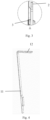
Fig. 1 shows a side view in which a monitoring system for a personnel delivery equipment according to the present disclosure is installed to the personnel delivery equipment, which takes an escalator as an example. -
Fig. 2 shows a front view in which a monitoring system for a personnel delivery equipment according to the present disclosure is installed to the personnel delivery equipment. -
Fig. 3 shows an enlarged view of a part A inFig. 2 . -
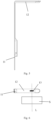
Fig. 4 shows a perspective view of a support member of a monitoring system. -
Fig. 5 shows a front view of a support member of a monitoring system. -
Fig. 6 shows a bottom view of a support member of a monitoring system. -
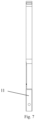
Fig. 7 shows a side view of a support member of a monitoring system. -
Fig. 8 shows a support member forming an inverted U-shaped configuration upon two personnel delivery equipment being arranged side by side. -
Fig. 9 shows a support member forming a T-shaped configuration upon two personnel delivery equipment being arranged side by side. -
Fig. 10 shows a support member provided at a platform section and an inclined section of a personnel delivery equipment. -
Fig. 11 shows a support member provided at a moving sidewalk. - Various embodiments according to the present disclosure will be described in detail with reference to the accompanying drawings. Herein, it should be noted that in the drawings, the same reference numerals are given to components having basically the same or similar structures and functions, and repeated descriptions about them will be omitted. The term "including A, B, C, etc. in sequence" only indicates the arrangement order of included components A, B, C, etc., and does not exclude the possibility of including other components between A and B and/or between B and C.
- The drawings in this specification are schematic diagrams to help explain the concept of the present disclosure, and schematically show the shapes of various parts and their relationships.
- Hereinafter, with reference to
Figs. 1 to 11 , preferred embodiments according to the present disclosure will be described in detail. - The monitoring system according to the present disclosure is used for monitoring a personnel delivery equipment. In the following description, an escalator is taken as an example to describe the monitoring system, but those skilled in the art will understand that the monitoring system of the present disclosure can also be applied to other personnel delivery equipment, such as a moving sidewalk.
- As illustrated by
Figs. 1 and 2 , the monitoring system includes asupport member 1 and a detection device, the support member is arranged close to and/or on the personnel delivery equipment, preferably between aguardrail 2 of an escalator and anouter edge 3 of the personnel delivery equipment. At least a part of the support member is arranged above a personnel delivery unit (such as a step or a pedal), and the detection device is arranged in the part of the support member located above the step to obtain detection information (such as image information, etc.) on the step. The detection device includes a camera, and a center line of the camera is preferably aligned with a center line of the step S of the escalator (as shown by "L" inFig. 6 ), so that the detection information can be obtained more accurately. The "Above" in the present disclosure should be understood as an projection of the detection device on the personnel delivery equipment is within the range of the personnel delivery equipment, that is, the detection device does not exceed the range of the personnel delivery equipment. - In one example, the support member includes an L-shaped configuration, which includes a first part arranged on the personnel delivery equipment and a second part extending transversely and perpendicular to the first part, and the detection device is arranged in the second part. In another example, the support member includes an inverted U-shaped configuration, which includes two first parts arranged on both sides of the escalator and a second part connecting the two first parts, the second part is located above the step and the detection device is arranged in the second part. Although the present disclosure is described with the support members with an L-shaped configuration and an inverted U-shaped configuration, it should be understood by those skilled in the art that the support member is not limited to the L-shaped configuration and the inverted U-shaped configuration, as long as the purpose of the present disclosure can be achieved. Preferably, a plurality of support members can be provided, are arranged along a running direction of the escalator, and can be arranged at the platform section and the inclined section of the escalator, for example, as illustrated by
Fig. 10 . In the case that a plurality of support members are provided, it is advantageous that the detection devices of the plurality of support members are arranged in a straight line parallel to the running direction of the escalator, so that the detection devices can cover the whole running area of the escalator. In the case that a plurality of support members are provided, a part of the support members can be arranged close to the escalator (such as the ground) and the other part of the support members can be arranged on the escalator. Of course, all the support members can only be arranged close to the escalator or on the escalator. - The following description is only for a L-shaped support member, and those skilled in the art will understand that such description is also applicable to support members with other shapes.
- As illustrated by
Figs. 4 to 7 , each L-shaped support member includes afirst part 11 and asecond part 12 extending from the first part, which enables thefirst part 11 to be fixed between the guardrail of the escalator and the outer edge of the escalator, and thesecond part 12 is located above the step of the escalator. The first part includes a rectangular cross section. Advantageously, a short edge of the rectangular cross section is perpendicular to the guardrail of the escalator, and a long edge of the rectangular cross section is parallel to the guardrail. The first part is installed to be laterally spaced apart from theguardrail 2 at the handrail belt by a predetermined distance (as illustrated byFig. 3 ). Through the rectangular cross section, the distance between the first part and the guardrail of the handrail belt can be controlled more conveniently, so that the distance meets the standard and passengers can be prevented from pinching their hands when using the handrail. At the same time, the outer surface of the first part away from the guardrail is flush with theouter edge 3 of the escalator, thus achieving a better appearance of the escalator. - The
detection device 13 is installed in the second part of the support member so that the camera is located above the step, preferably directly above the step. The light source, voice device and artificial intelligence module are arranged on the support member, advantageously, the light source and the voice device are arranged on the second part, and the artificial intelligence module is arranged on the first part. In this way, the image or video of the escalator is obtained by the detection device, and the analysis result is output to the voice device through the analysis of the image or video by the artificial intelligence module, so as to remind the user of the situation of the escalator. - In the case that two escalators are arranged side by side, the first part of the L-shaped support members of their respective monitoring systems can be common, and the two second parts respectively extend above the steps of their respective escalators, so that the two L-shaped support members form a T-shaped configuration, as illustrated by
Fig. 8 . In this case, the two L-shaped support members can be integrated or separated from each other. - Alternatively, in the case that two escalators are arranged side by side, the second parts of the L-shaped support members of their respective monitoring systems contact each other, so that the two L-shaped support members form an inverted U-shaped configuration, as illustrated by
Fig. 9 . In this case, the two L-shaped support members can be integrated or separated from each other. -
Fig. 11 exemplarily shows a case of a moving sidewalk, and a plurality of supports are arranged close to or on the moving sidewalk. - By arranging the support member of the monitoring system on the escalator and arranging the detection device in the part of the support member located above the step, the detection device can stably obtain the image of the personnel delivery equipment.
- The above description is only an explanation of the present disclosure, which enables those skilled in the art to fully implement the scheme, but it is not a limitation of the present disclosure. The technical features disclosed above are not limited to the combination with other features, and those skilled in the art can also combine other technical features according to the purpose of the present disclosure, so as to achieve the purpose of the present disclosure.
Claims (15)
- A monitoring system for a personnel delivery equipment, which is characterized in that, the monitoring system comprises:a support member, arranged close to and/or on the personnel delivery equipment, wherein at least a part of the support member is located above a personnel delivery unit of the personnel delivery equipment;a detection device, arranged in the at least a part of the support member above the personnel delivery unit so that the detection device is located above the personnel delivery unit to obtain detection information on the personnel delivery unit of the personnel delivery equipment.
- The monitoring system according to claim 1, which is characterized in that the support member is arranged between a guardrail of the personnel delivery equipment and an outer edge of the personnel delivery equipment.
- The monitoring system according to claim 1, which is characterized in that the detection device comprises a camera, and a center line of the camera coincides with a center line of the personnel delivery unit.
- The monitoring system according to claim 1, which is characterized in that the monitoring system comprises a plurality of support members, and the plurality of support members are arranged so that detection devices of the plurality of support members are arranged along a straight line parallel to a running direction of the personnel delivery equipment, so as to cover a whole running area of the personnel delivery equipment.
- The monitoring system according to claim 1, which is characterized in that the monitoring system comprises a plurality of support members, and the plurality of support members are arranged at a platform section and an inclined section of the personnel delivery equipment.
- The monitoring system according to claim 1, which is characterized in that the support member is L-shaped, and comprises a first part and a second part extending transversely and perpendicular to the first part, wherein the first part is arranged on the personnel delivery equipment, the second part is located above the personnel delivery unit, and the detection device is arranged in the second part.
- The monitoring system according to claim 1, which is characterized in that the support is inverted U-shaped, and comprises two first parts arranged on both sides of the personnel delivery equipment and a second part connecting the two first parts, wherein the first parts are arranged on the personnel delivery equipment, the second part is located above the personnel delivery unit, and the detection device is arranged in the second part.
- The monitoring system according to claim 6, which is characterized in that the first part of the support member comprises a rectangular cross section.
- The monitoring system according to claim 2, which is characterized in that the first part of the support member is laterally spaced apart from the guardrail at a handrail belt by a predetermined distance, and an outer surface of the first part away from the guardrail is flush with the outer edge of the personnel delivery system.
- The monitoring system according to any one of claims 1 to 7, which is characterized in that the monitoring system further comprises a light source arranged on the support member.
- The monitoring system according to any one of claims 1 to 7, which is characterized in that the monitoring system further comprises a voice device arranged on the support member.
- The monitoring system according to any one of claims 1 to 7, which is characterized in that the monitoring system further comprises an artificial intelligence module arranged on the support member.
- The monitoring system according to claim 6, which is characterized in that, in a case that two personnel delivery equipment are arranged side by side, the first part of the L-shaped support members of the monitoring system of the two personnel delivery equipment is common, and second parts extend above personnel delivery units of the two personnel delivery equipment respectively, so that the two L-shaped support members form a T-shaped configuration.
- The monitoring system according to claim 6, which is characterized in that, in a case that two personnel delivery equipment are arranged side by side, second parts of the L-shaped support members of the monitoring system of the two personnel delivery equipment are in contact with each other, so that the two L-shaped supports form an inverted U-shaped configuration.
- A personnel delivery equipment, which is characterized in that the personnel delivery equipment comprises the monitoring system according to claim 1.
Applications Claiming Priority (2)
| Application Number | Priority Date | Filing Date | Title |
|---|---|---|---|
| CN202110959209.0A CN113636437A (en) | 2021-08-20 | 2021-08-20 | Monitoring system for personnel conveying equipment and personnel conveying equipment |
| PCT/CN2022/112364 WO2023020411A1 (en) | 2021-08-20 | 2022-08-15 | Monitoring system for personnel delivery equipment, and personnel delivery equipment |
Publications (2)
| Publication Number | Publication Date |
|---|---|
| EP4389674A1 true EP4389674A1 (en) | 2024-06-26 |
| EP4389674A4 EP4389674A4 (en) | 2025-07-30 |
Family
ID=78423166
Family Applications (1)
| Application Number | Title | Priority Date | Filing Date |
|---|---|---|---|
| EP22857723.5A Pending EP4389674A4 (en) | 2021-08-20 | 2022-08-15 | MONITORING SYSTEM FOR PERSONNEL DELIVERY EQUIPMENT AND PERSONNEL DELIVERY EQUIPMENT |
Country Status (3)
| Country | Link |
|---|---|
| EP (1) | EP4389674A4 (en) |
| CN (1) | CN113636437A (en) |
| WO (1) | WO2023020411A1 (en) |
Families Citing this family (1)
| Publication number | Priority date | Publication date | Assignee | Title |
|---|---|---|---|---|
| CN113636437A (en) * | 2021-08-20 | 2021-11-12 | 通力电梯有限公司 | Monitoring system for personnel conveying equipment and personnel conveying equipment |
Family Cites Families (12)
| Publication number | Priority date | Publication date | Assignee | Title |
|---|---|---|---|---|
| JPH11349269A (en) * | 1998-06-08 | 1999-12-21 | Hitachi Ltd | Monitoring and control equipment for man conveyor equipment |
| JP5048912B2 (en) * | 2002-11-06 | 2012-10-17 | インベンテイオ・アクテイエンゲゼルシヤフト | Surveillance and moving walkway video camera surveillance |
| EP1419988A1 (en) * | 2002-11-06 | 2004-05-19 | Inventio Ag | Stereoscopic monitoring system for escalators and moving walkways |
| CN103863934B (en) * | 2014-04-02 | 2016-02-03 | 日立电梯(广州)自动扶梯有限公司 | Escalator safety detection device and method |
| DE102015214764A1 (en) * | 2015-08-03 | 2017-02-09 | Thyssenkrupp Ag | Passenger conveying device with monitoring device |
| JP6502546B1 (en) * | 2018-02-23 | 2019-04-17 | 東芝エレベータ株式会社 | Passenger conveyor |
| JP7001557B2 (en) * | 2018-07-11 | 2022-01-19 | 株式会社日立製作所 | Passenger conveyor and passenger conveyor control method |
| CN110227655A (en) * | 2019-04-29 | 2019-09-13 | 丽水奇异果信息技术有限公司 | A kind of chip-detecting apparatus based on image recognition |
| CN211812976U (en) * | 2019-12-27 | 2020-10-30 | 山东职业学院 | Control device for visiting passenger conveying equipment |
| CN111695528A (en) * | 2020-06-15 | 2020-09-22 | 安徽省徽腾智能交通科技有限公司 | Face image recognition method and recognition device thereof |
| CN113636437A (en) * | 2021-08-20 | 2021-11-12 | 通力电梯有限公司 | Monitoring system for personnel conveying equipment and personnel conveying equipment |
| CN216235540U (en) * | 2021-08-20 | 2022-04-08 | 通力电梯有限公司 | Monitoring system for personnel conveying equipment and personnel conveying equipment |
-
2021
- 2021-08-20 CN CN202110959209.0A patent/CN113636437A/en active Pending
-
2022
- 2022-08-15 EP EP22857723.5A patent/EP4389674A4/en active Pending
- 2022-08-15 WO PCT/CN2022/112364 patent/WO2023020411A1/en not_active Ceased
Also Published As
| Publication number | Publication date |
|---|---|
| WO2023020411A1 (en) | 2023-02-23 |
| CN113636437A (en) | 2021-11-12 |
| EP4389674A4 (en) | 2025-07-30 |
Similar Documents
| Publication | Publication Date | Title |
|---|---|---|
| US11288904B2 (en) | Gate device and system | |
| WO2021132935A1 (en) | System for detecting pedestrian at crosswalk and preventing accident on basis of artificial intelligence | |
| JP4353763B2 (en) | Automatic operation type man conveyor | |
| EP3533747A1 (en) | Passenger conveyor | |
| WO2023020411A1 (en) | Monitoring system for personnel delivery equipment, and personnel delivery equipment | |
| CN216235540U (en) | Monitoring system for personnel conveying equipment and personnel conveying equipment | |
| JP7435882B1 (en) | Destination floor registration device | |
| EP3447021B1 (en) | Transport device | |
| EP4395293A1 (en) | Monitoring system for personnel delivery device and personnel delivery device | |
| WO2022166826A1 (en) | Passenger transport apparatus | |
| KR102407557B1 (en) | a floor cover arrangement for covering the underfloor space of a passenger conveyor | |
| JP2001278048A (en) | Train getting-on/off position guide system | |
| JP7272479B1 (en) | elevator display system | |
| JPH02300089A (en) | Safety device for man conveyer | |
| JP2003335490A (en) | Man conveyor with handrail illuminating device | |
| CN218205329U (en) | Braille handrail for visually impaired people | |
| CN210340042U (en) | Elevator layer door crossbeam convenient to observe | |
| CN110467100A (en) | The step ladder and apparatus of passenger conveyor of apparatus of passenger conveyor | |
| JP2016132550A (en) | Passenger conveyor | |
| KR102938906B1 (en) | Foot Entrapment Prevention Warning System for Platform Screen Doors | |
| CN221027089U (en) | Mounting structure of front apron board of passenger conveyor | |
| EP3248927A1 (en) | Emergency button | |
| JPH07300827A (en) | Passing sheet for the visually impaired | |
| JP2014227270A (en) | Lighting system for escalator entrance | |
| CN216997217U (en) | Moving sidewalk with function of displaying running direction in transparent large area |
Legal Events
| Date | Code | Title | Description |
|---|---|---|---|
| STAA | Information on the status of an ep patent application or granted ep patent |
Free format text: STATUS: THE INTERNATIONAL PUBLICATION HAS BEEN MADE |
|
| PUAI | Public reference made under article 153(3) epc to a published international application that has entered the european phase |
Free format text: ORIGINAL CODE: 0009012 |
|
| STAA | Information on the status of an ep patent application or granted ep patent |
Free format text: STATUS: REQUEST FOR EXAMINATION WAS MADE |
|
| 17P | Request for examination filed |
Effective date: 20240318 |
|
| AK | Designated contracting states |
Kind code of ref document: A1 Designated state(s): AL AT BE BG CH CY CZ DE DK EE ES FI FR GB GR HR HU IE IS IT LI LT LU LV MC MK MT NL NO PL PT RO RS SE SI SK SM TR |
|
| DAV | Request for validation of the european patent (deleted) | ||
| DAX | Request for extension of the european patent (deleted) | ||
| RAP1 | Party data changed (applicant data changed or rights of an application transferred) |
Owner name: KONE CORPORATION |
|
| P01 | Opt-out of the competence of the unified patent court (upc) registered |
Free format text: CASE NUMBER: APP_859/2025 Effective date: 20250108 |
|
| A4 | Supplementary search report drawn up and despatched |
Effective date: 20250630 |
|
| RIC1 | Information provided on ipc code assigned before grant |
Ipc: B66B 21/02 20060101AFI20250624BHEP Ipc: B66B 23/22 20060101ALI20250624BHEP Ipc: B66B 23/00 20060101ALI20250624BHEP Ipc: B66B 29/00 20060101ALI20250624BHEP |