EP4389631A1 - Ensemble fermeture à glissière d'une enceinte refermable - Google Patents
Ensemble fermeture à glissière d'une enceinte refermable Download PDFInfo
- Publication number
- EP4389631A1 EP4389631A1 EP23216875.7A EP23216875A EP4389631A1 EP 4389631 A1 EP4389631 A1 EP 4389631A1 EP 23216875 A EP23216875 A EP 23216875A EP 4389631 A1 EP4389631 A1 EP 4389631A1
- Authority
- EP
- European Patent Office
- Prior art keywords
- posts
- flange
- panel side
- zipper assembly
- enclosure
- Prior art date
- Legal status (The legal status is an assumption and is not a legal conclusion. Google has not performed a legal analysis and makes no representation as to the accuracy of the status listed.)
- Pending
Links
- 238000007789 sealing Methods 0.000 claims abstract description 47
- 230000006835 compression Effects 0.000 claims abstract description 44
- 238000007906 compression Methods 0.000 claims abstract description 44
- 238000000926 separation method Methods 0.000 claims abstract description 20
- 239000000853 adhesive Substances 0.000 claims description 60
- 230000001070 adhesive effect Effects 0.000 claims description 60
- 238000000034 method Methods 0.000 claims description 50
- 239000000565 sealant Substances 0.000 claims description 41
- 239000000463 material Substances 0.000 claims description 35
- 239000010410 layer Substances 0.000 description 14
- 230000000712 assembly Effects 0.000 description 5
- 238000000429 assembly Methods 0.000 description 5
- 230000007547 defect Effects 0.000 description 5
- 238000004519 manufacturing process Methods 0.000 description 2
- 229920000642 polymer Polymers 0.000 description 2
- 239000004820 Pressure-sensitive adhesive Substances 0.000 description 1
- 239000012790 adhesive layer Substances 0.000 description 1
- 239000003814 drug Substances 0.000 description 1
- 239000006261 foam material Substances 0.000 description 1
- 230000006870 function Effects 0.000 description 1
- 238000002955 isolation Methods 0.000 description 1
- 239000002699 waste material Substances 0.000 description 1
Images


Classifications
-
- B—PERFORMING OPERATIONS; TRANSPORTING
- B65—CONVEYING; PACKING; STORING; HANDLING THIN OR FILAMENTARY MATERIAL
- B65D—CONTAINERS FOR STORAGE OR TRANSPORT OF ARTICLES OR MATERIALS, e.g. BAGS, BARRELS, BOTTLES, BOXES, CANS, CARTONS, CRATES, DRUMS, JARS, TANKS, HOPPERS, FORWARDING CONTAINERS; ACCESSORIES, CLOSURES, OR FITTINGS THEREFOR; PACKAGING ELEMENTS; PACKAGES
- B65D33/00—Details of, or accessories for, sacks or bags
- B65D33/16—End- or aperture-closing arrangements or devices
- B65D33/25—Riveting; Dovetailing; Screwing; using press buttons or slide fasteners
- B65D33/2508—Riveting; Dovetailing; Screwing; using press buttons or slide fasteners using slide fasteners with interlocking members having a substantially uniform section throughout the length of the fastener; Sliders therefor
-
- A—HUMAN NECESSITIES
- A44—HABERDASHERY; JEWELLERY
- A44B—BUTTONS, PINS, BUCKLES, SLIDE FASTENERS, OR THE LIKE
- A44B19/00—Slide fasteners
- A44B19/02—Slide fasteners with a series of separate interlocking members secured to each stringer tape
-
- A—HUMAN NECESSITIES
- A44—HABERDASHERY; JEWELLERY
- A44B—BUTTONS, PINS, BUCKLES, SLIDE FASTENERS, OR THE LIKE
- A44B19/00—Slide fasteners
- A44B19/42—Making by processes not fully provided for in one other class, e.g. B21D53/50, B21F45/18, B22D17/16, B29D5/00
-
- B—PERFORMING OPERATIONS; TRANSPORTING
- B65—CONVEYING; PACKING; STORING; HANDLING THIN OR FILAMENTARY MATERIAL
- B65B—MACHINES, APPARATUS OR DEVICES FOR, OR METHODS OF, PACKAGING ARTICLES OR MATERIALS; UNPACKING
- B65B61/00—Auxiliary devices, not otherwise provided for, for operating on sheets, blanks, webs, binding material, containers or packages
- B65B61/18—Auxiliary devices, not otherwise provided for, for operating on sheets, blanks, webs, binding material, containers or packages for making package-opening or unpacking elements
- B65B61/188—Auxiliary devices, not otherwise provided for, for operating on sheets, blanks, webs, binding material, containers or packages for making package-opening or unpacking elements by applying or incorporating profile-strips, e.g. for reclosable bags
-
- B—PERFORMING OPERATIONS; TRANSPORTING
- B65—CONVEYING; PACKING; STORING; HANDLING THIN OR FILAMENTARY MATERIAL
- B65D—CONTAINERS FOR STORAGE OR TRANSPORT OF ARTICLES OR MATERIALS, e.g. BAGS, BARRELS, BOTTLES, BOXES, CANS, CARTONS, CRATES, DRUMS, JARS, TANKS, HOPPERS, FORWARDING CONTAINERS; ACCESSORIES, CLOSURES, OR FITTINGS THEREFOR; PACKAGING ELEMENTS; PACKAGES
- B65D33/00—Details of, or accessories for, sacks or bags
- B65D33/16—End- or aperture-closing arrangements or devices
- B65D33/25—Riveting; Dovetailing; Screwing; using press buttons or slide fasteners
- B65D33/2508—Riveting; Dovetailing; Screwing; using press buttons or slide fasteners using slide fasteners with interlocking members having a substantially uniform section throughout the length of the fastener; Sliders therefor
- B65D33/2541—Riveting; Dovetailing; Screwing; using press buttons or slide fasteners using slide fasteners with interlocking members having a substantially uniform section throughout the length of the fastener; Sliders therefor characterised by the slide fastener, e.g. adapted to interlock with a sheet between the interlocking members having sections of particular shape
-
- B—PERFORMING OPERATIONS; TRANSPORTING
- B65—CONVEYING; PACKING; STORING; HANDLING THIN OR FILAMENTARY MATERIAL
- B65D—CONTAINERS FOR STORAGE OR TRANSPORT OF ARTICLES OR MATERIALS, e.g. BAGS, BARRELS, BOTTLES, BOXES, CANS, CARTONS, CRATES, DRUMS, JARS, TANKS, HOPPERS, FORWARDING CONTAINERS; ACCESSORIES, CLOSURES, OR FITTINGS THEREFOR; PACKAGING ELEMENTS; PACKAGES
- B65D85/00—Containers, packaging elements or packages, specially adapted for particular articles or materials
- B65D85/67—Containers, packaging elements or packages, specially adapted for particular articles or materials for web or tape-like material
- B65D85/671—Containers, packaging elements or packages, specially adapted for particular articles or materials for web or tape-like material wound in flat spiral form
Definitions
- the subject matter described herein relates to zipper assemblies of resealable enclosures, such as bags, pouches, or the like, that can be repeatedly opened and closed using interlocking members of the zipper assemblies.
- Resealable enclosures are used to store a variety of materials.
- pouches, bags, or the like can be used to store food, pharmaceuticals, or other consumer products and may include resealable closure assemblies.
- closure assemblies include a zipper assembly attached to an end of the bag or enclosure.
- the zipper assembly is attached to the enclosure during a heat sealing process in which heat is applied to the zipper assembly and/or the enclosure during an application process to activate and/or cure an adhesive layer between the zipper assembly and the enclosure.
- the heat applied during the application process may damage the zipper assembly and/or the enclosure, such as by scorching the materials leading to waste.
- Some zipper assemblies use cold seal adhesive to apply the zipper assembly to the enclosure, which may be applied at or near room temperature.
- cold seal adhesive may be inadvertently attached to other portions of the zipper assembly.
- long lengths of the zipper assembly may be rolled on a supply roll in many layers.
- the cold seal adhesive from one layer of the zipper assembly may inadvertently seal to an adjacent layer of the zipper assembly leading to damage to the seal layer and/or the material of the zipper assembly.
- a zipper assembly for an enclosure includes a flange having an interlocking side and an opposite panel side.
- the interlocking side has interlocking members configured to releasably engage and release from other interlocking members to alternate between closed and open states of the enclosure.
- the panel side is configured to be sealed to panels of the enclosure to affix the zipper assembly to the enclosure.
- the zipper assembly includes posts protruding from the panel side of the flange.
- the posts are configured to prevent compression of the posts and maintain a spatial separation between the panel side of the flange and the interlocking side of the flange while the zipper assembly is wound onto a supply roll.
- the posts are configured to collapse upon compression of the posts during sealing of the panel side of the flange to the panels of the enclosure to allow the panel side of the flange to be sealed to the panels.
- a method for forming a zipper assembly for an enclosure includes forming the zipper assembly to have a flange with an interlocking side and an opposite panel side.
- the flange is formed with interlocking members protruding from the interlocking side and positioned to releasably engage and release from other interlocking members to alternate between closed and open states of the enclosure.
- the flange also is formed with the panel side positioned to be sealed to panels of the enclosure to affix the zipper assembly to the enclosure.
- the zipper assembly is formed to have posts protruding from the panel side of the flange.
- the posts are formed to prevent compression of the posts and maintain a spatial separation between the panel side of the flange and the interlocking side of the flange while the zipper assembly is wound onto a supply roll.
- the posts are formed to collapse upon compression of the posts during sealing of the panel side of the flange to the panels of the enclosure to allow the panel side of the flange to be sealed to the panels.
- a zipper assembly for an enclosure includes a flange having an interlocking side and an opposite panel side.
- the interlocking side has interlocking members protruding from first areas of the interlocking side and shaped to releasably engage and release from other interlocking members to alternate between closed and open states of the enclosure.
- the panel side is configured to be cold sealed to panels of the enclosure to affix the zipper assembly to the enclosure.
- the zipper assembly includes posts protruding from the panel side of the flange in second areas of the flange side. The posts are configured to prevent compression of the posts and maintain a spatial separation between the panel side of the flange and the interlocking side of the flange while the zipper assembly is wound onto a supply roll.
- the posts are configured to collapse upon compression of the posts during cold sealing of the panel side of the flange to the panels of the enclosure to allow the panel side of the flange to be sealed to the panels.
- FIG. 1 illustrates a zipper assembly 100 in accordance with an exemplary embodiment providing a resealable closure assembly for an enclosure 10.
- the zipper assembly 100 includes interlocking first and second zipper profile members 104, 106.
- the zipper assembly 100 may include a slider (not shown) for opening and closing the zipper profile members 104, 106 in various embodiments.
- the zipper assembly 100 is applied to the enclosure 10 during an application process, such as using pressure sensitive adhesive, to provide a reclosable or resealable closure assembly.
- the zipper assembly 100 is applied to the enclosure 10 during a cold seal adhesive using a cold seal application process to provide a reclosable or resealable closure assembly.
- the enclosure 10 may be a bag, pouch, or other container.
- the enclosure 10 is formed from one or more webs 12 of flexible material (e.g., a polymer). These webs 12 form one or more of the panels 14, 16, which are attached to the zipper assembly 100 during the application process.
- the zipper assembly 100 is attached to the panels 14, 16 using adhesive 30 between the zipper assembly 100 and the panels 14, 16.
- the adhesive 30 may be a cold seal adhesive applied by a cold seal process, which can be applied without adding heat during the application process. The cold sealing process can increase processing speed and eliminate heat sealing marks and other defects from heat sealing, thus improving the overall look of the finished product.
- first and second zipper profile members 104, 106 include respective first and second flanges 108, 110 and respective first and second interlocking members 112, 114.
- the first and second flanges 108, 110 are configured to be attached to the respective first and second panels 14, 16 using the adhesive 30 during an application process.
- the first and second flanges 108, 110 have respective interlocking sides 130, 132 and opposite panel sides 134, 136.
- the interlocking sides 130, 132 are inward facing.
- the panel sides 134, 136 are outward facing.
- the interlocking sides 130, 132 have the corresponding interlocking members 112, 114 extending therefrom, which are configured to releasably engage and release from other interlocking members to alternate between closed and open states of the enclosure 10.
- the panel sides 134, 136 are configured to be sealed to the corresponding panels 14, 16 of the enclosure 10 to affix the zipper assembly 100 to the enclosure 10.
- the first interlocking member 112 includes first and second arms 116, 118 that form a female configuration or female interlocking zipper member.
- the first and second arms 116, 118 form a receptacle or track 120 that receives the second interlocking member 114.
- the second interlocking member 114 includes a third arm 122 forming a male configuration or male interlocking zipper member.
- the third arm 122 includes a head 124 received in the track 120.
- the male zipper member is received and meshes with the female zipper member of the first interlocking member 112.
- Other types of interlocking members such as interlocking members having other shapes or interlocking features, may be used in alternative embodiments.
- One or more embodiments of the inventive subject matter described herein include posts 40 protruding from the panel sides 134, 136 of the flanges 108, 110 proximate to the sealant area of the adhesive 30.
- the posts 40 are compressible above a threshold compression force, which may be controlled by selecting the size, shape and type of material of the posts 40 depending on the particular application (for example, typical compressive forces for shipping versus application to the enclosure).
- the posts 40 are used to prevent inadvertent sealing of the adhesive 30 to other layers of the length of zipper assembly when the zipper assembly is arranged on a supply roll (for example, during shipping and prior to application to the enclosure 10).
- the posts 40 are configured to prevent compression of the posts 40 and maintain a spatial separation between the panel sides 134, 136 of the flanges 108, 110 and the interlocking side 130, 132 of the flanges 108, 110 of an adjacent layer of the zipper assembly 100 within the supply roll.
- the posts 40 are configured to collapse upon compression of the posts 40 during sealing of the panel sides 134, 136 of the flanges 108, 110 to the panels 14, 16 of the enclosure 10 to allow the panel sides 134, 136 of the flanges 108, 110 to be sealed to the panels 14, 16.
- the posts 40 are capable of withstanding a predetermined compression force, which is higher than the compressive forces experienced on the supply roll (for example, approximately ten pounds per square inch) but less than the compressive forces typical of application of the zipper assembly 100 to the enclosure 10 (for example, approximately one hundred pounds per square inch).
- the posts 40 allow the use of cold seal adhesive by preventing the inadvertent sealing of the adhesive to other portions of the length of the zipper assembly while on the supply roll by maintaining spatial separation of the adhesive from such other elements on the supply roll.
- the cold sealing process can increase processing speed and eliminate heat sealing marks and other defects from heat sealing, thus improving the overall look of the finished product.
- Figure 2 is a cross sectional view of a length of the zipper assembly 100 wound on a spool or supply reel 150 to form a supply roll 152 of the zipper assembly 100.
- the supply reel 150 includes a hub 154 and sidewalls 156.
- the supply roll 152 is wound on the hub 154 between the sidewalls 156 in multiple layers 158.
- the posts 40 spatially separate the adhesive 30 from other layers 158 of the zipper assembly to prevent inadvertent adhesion to such other layers while in the supply roll 152.
- the posts 40 are capable of withstanding compressive forces, such as from the weight of the other layers on the supply reel 150, to maintain the spatial separation.
- FIG. 3 is a schematic view of an assembly process for manufacturing the enclosures 10.
- the zipper assembly 100 is manufactured as a continuous length of zipper assembly.
- the two zipper profile members 104, 106 of the zipper assembly 100 may be extruded and may be assembled together in a continuous strip.
- the adhesive 30 is applied to the zipper assembly 100, such as to the panel sides of the flanges of the zipper profile members 104, 106.
- the adhesive coupled be co-extruded with the profile members 104, 106, such as extruded at the same time and in conjunction with the profile members 104, 106, such as at the same station.
- the posts are applied to the zipper profile members 104, 106.
- the posts 40 may be applied at the first station 300 (for example, formed with the zipper profile members 104, 106) or may be applied at the second station 302, such as being applied with the adhesive 30.
- the continuous strip of zipper assembly 100 is wound on the supply reel 150.
- the posts 40 maintain isolation or separation of the adhesive 30 from other layers within the supply roll.
- the zipper assembly 100 is unwound and arranged along the panels 14, 16 of the enclosure 10.
- the zipper assembly 100 is applied to the panels 14, 16, such as using pressure.
- the adhesive is cold seal adhesive and may be applied with little or no heat application to avoid damaging the panels 14, 16 or the zipper assembly 100 from scorching or other damage from heat application that may occur during hot press applications.
- the cold sealing process can increase processing speed and eliminate heat sealing marks and other defects from heat sealing, thus improving the overall look of the finished product.
- the posts 40 are crushed during application of the zipper assembly 100 to the panels 14, 16 to allow direct connection of the panels 14, 16 to the adhesive 30.
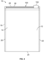
- FIG 4 illustrates one example of the enclosure 10 having the zipper assembly 100.
- the enclosure 10 is formed from one or more of the webs 12 of flexible material (e.g., a polymer).
- the webs 12 form the panels 14, 16 that are joined or otherwise closed along opposing side edges 20, 22 and a bottom edge 24 of the enclosure 10.
- the enclosure 10 is formed from multiple webs 12 of material as the panels 14, 16, then the panels 14, 16 may be sealed to each other along the edges 20, 22, 24 to enclose or bound an interior chamber or volume.
- the enclosure 10 is formed from a single web 12 (e.g., a tube of the web material), then the tube of web material can be sealed along one of the edges 20, 22 or 24 to enclose or bound the interior chamber or volume (and may include a fin or lap seal running vertically on one of the faces or panels).
- the panels 14, 16 can be different portions of this single web on opposite sides of the interior chamber or volume.
- the panel 14 is shown in Figure 4 with the panel 16 located behind the panel 14 (on the opposite side of the enclosure 10).
- the zipper assembly 100 can be disposed along upper edges 26, 28 of the panels 14, 16, such as by cold sealing the zipper assembly 100 to the upper edges 26, 28 of the panels 14, 16.
- the zipper assembly 100 can include a slider 102 that is used to open the zipper assembly 100 to provide access into the enclosure 10 and that is used to close the zipper assembly 100 to prevent access into the enclosure 10.
- Figure 5 is a side, exploded view of the zipper assembly 100 in accordance with an exemplary embodiment.
- Figure 5 shows the first and second zipper profile members 104, 106 in an open configuration.
- Figure 5 shows the panels 14, 16 positioned outside of the zipper profile members 104, 106.
- the zipper profile members 104, 106 are configured to be applied to the upper edges 26, 28 of the panels 14, 16.
- the upper edges 26, 28 may be connected to form a closed portion above the zipper profile members, at least a portion of which may be removable (for example, perforated tabs) by the end user to expose the zipper assembly 100.
- the first and second zipper profile members 104, 106 include the first and second flanges 108, 110 and the respective first and second interlocking members 112, 114 at the interlocking sides 130, 132 of the flanges 108, 110.
- the panel sides 134, 136, at the outer sides of the flanges 108, 110, are configured to be sealed to the corresponding panels 14, 16 of the enclosure 10.
- the adhesive 30 is applied in sealant areas 32 along the panel sides 134, 136 of the flanges 108, 110. In the illustrated embodiment, the sealant areas 32 are located above and below the interlocking members 112, 114.
- the sealant areas 32 may be located on the panel sides 134, 136 only above or only below the interlocking members 112, 114.
- the interlocking members 112, 114 may be located at the upper ends of the flanges 108, 110 such that the flanges 108, 110 do not include any portion above the interlocking members 112, 114.
- the sealant areas 32 are located only below the interlocking members 112, 114.
- the interlocking members 112, 114 may be located at the lower ends of the flanges 108, 110 such that the flanges 108, 110 do not include any portion below the interlocking members 112, 114.
- the sealant areas 32 are located only above the interlocking members 112, 114.
- Figure 6 is an end view of a portion of the zipper assembly 100 in accordance with an exemplary embodiment
- Figure 6 shows the outer end of the first zipper profile member 104 (however, the second zipper profile member 106 may include a similar arrangement of the adhesive 30 and posts 40).
- the posts 40 are provided at the sealant areas 32.
- multiple posts 40 are provided in each sealant area 32.
- the posts 40 may be arranged in rows and columns.
- the posts 40 are spaced apart by distances, which may be short enough to prevent inadvertent sealing of the adhesive 30 to other layers of the length of zipper assembly when the zipper assembly is arranged on the supply roll (for example, during shipping and prior to application to the enclosure 10).
- the posts 400 could be ribs, such as continuous ribs, running along the length of the profile members 104, 106.
- Each post 40 includes a base 42 and a tip 44 at a distal end of the post 40.
- the post 40 includes a sidewall 46 between the base 42 and the tip 44.
- the base 42 is provided at the corresponding flange 108, 110.
- the base 42 may be attached to the flange 108, 110, such as using adhesive.
- the post 40 may be manufactured from a foam material.
- the post 40 may be manufactured from a plastic material.
- the post 40 may be integral with the flange 108, 110, such as being molded or extruded with the flange 108, 110.
- the post 40 may be manufactured from the same material and during the same forming process as the flange 108, 110.
- the post 40 has a width between the base 42 and the tip 44.
- the width is greater than a thickness of the adhesive 30 such that the tip 44 is positioned to protrude from the corresponding panel side 134, 136 of the flange 108, 110 beyond the outer surface of the adhesive 30.
- the posts 40 are positioned and protrude from the panel side 134, 136 of the flange 108, 110 such that the posts 40 prevent the cold sealant adhesive 30 disposed on the panel side 134, 136 of the flange 108, 110 from adhering to other structures, such as the interlocking side 130, 132 of the flange 108, 110 when stacked in the layers of the supply roll.
- the post 40 has a circular cross-section.
- the post 40 may have a different shape in alternative embodiments.
- the post 40 may have a triangular cross-section, a rectangular cross-section, or another shape.
- the post 40 is pointed having the sidewall 46 tapered with the tip 44 being narrower than the base 42.
- the post 40 is cone shaped.
- the post 40 may be round shaped, square shaped, rectangular shaped, or have other shapes.
- the sidewall(s) 46 may extend perpendicular relative to the corresponding panel side 134, 136 with the base 42 having the same shape as the tip 44.
- the post 40 may be columnar.
- the posts 400 could be elongated, such as being continuous ribs running along the length of the profile members 104, 106.
- the posts 40 are one or more of formed of a shape or manufactured from a material that prevents collapse of the posts 40 upon receiving a stacking force, which is a force of stacking the zipper assembly 100 in the supply roll.
- the posts 40 are one or more of formed of a shape or manufactured from a material that prevents collapse of the posts 40 upon receiving no more than approximately ten pounds per square inch of compressive force.
- the posts 40 may be capable of withstanding a higher compressive force in other embodiments, such as a compressive force of approximately fifty pounds per square inch of compressive force. In other various embodiments, the posts 40 may be capable of withstanding even higher compressive forces, such as a compressive force of approximately one hundred pounds per square inch of compressive force.
- the posts 40 are configured to collapse upon compression of the posts 40 during cold sealing of the panel side 134, 136 of the flange 108, 110 to the panels 14, 16 of the enclosure 10 to allow the cold sealant adhesive 30 disposed on the panel side 134, 136 to be sealed between the panels 14, 16 and the panel side 134, 136 of the flange 108, 110.
- the posts 40 are one or more of formed of a shape or manufactured from a material that causes the posts 40 to collapse upon receiving a sealing force, which is a force of sealing the zipper assembly 100 to the panel 14, 16 of the enclosure 10.
- the posts 40 are one or more of formed of a shape or manufactured from a material that causes the posts 40 to collapse upon receiving at least approximately one hundred pounds per square inch of the compressive force.
- the posts 40 may be capable of compressing at lower compressive forces in other embodiments, such as a compressive force of approximately fifty pounds per square inch of compressive force.
- the posts 40 may be capable of compressing at even lower compressive forces, such as a compressive force of at least ten pounds per square inch of compressive force.
- Figure 7 is an end view of a portion of the zipper assembly 100 in accordance with an exemplary embodiment showing the outer end of the first zipper profile member 104 (however, the second zipper profile member 106 may include a similar arrangement of the adhesive 30 and posts 40).
- the posts 40 are provided at the sealant areas 32.
- the posts 40 are square shaped in the illustrated embodiment rather than being circular as shown in Figure 6 .
- the columns and rows of the posts 40 are staggered or offset rather than being aligned as shown in Figure 6 .
- Figure 8 is an end view of a portion of the zipper assembly 100 in accordance with an exemplary embodiment showing the outer end of the first zipper profile member 104 (however, the second zipper profile member 106 may include a similar arrangement of the adhesive 30 and posts 40).
- the posts 40 are provided at the sealant areas 32.
- the posts 40 are elongated, being rectangular shaped in the illustrated embodiment.
- Figure 9 illustrates a zipper assembly 200 having interlocking first and second zipper profile members 204, 206.
- the zipper assembly 200 may be applied to the enclosure 10 in place of the zipper assembly 100 (shown in Figure 5 ).
- the zipper assembly 200 has different zipper profile members having different shapes than the zipper profiles 104, 106 of the zipper assembly 100.
- Figure 9 shows a slider 202 used to open and close the zipper assembly 200.
- the zipper assembly 200 is attached to the panels 14, 16 using the adhesive 30 to provide a reclosable or resealable closure assembly.
- the compressible posts 40 are provided at the sealant areas 32.
- first and second zipper profile members 204, 206 include respective first and second flanges 208, 210 and respective first and second interlocking members 212, 214.
- the first and second flanges 208, 210 are configured to be attached to the respective first and second panels 14, 16 using the adhesive 30 during an application process.
- the first and second flanges have respective interlocking sides 230, 232 and opposite panel sides 234, 236.
- the interlocking sides 230, 232 are inward facing.
- the panel sides 234, 236 are outward facing.
- the interlocking sides 230, 232 have the corresponding interlocking members 212, 214 extending therefrom, which are configured to releasably engage and release from other interlocking members to alternate between closed and open states of the enclosure 10.
- the panel sides 234, 236 are configured to be sealed to the corresponding panels 14, 16 of the enclosure 10 to affix the zipper assembly 200 to the enclosure 10.
- the first interlocking member 212 includes first and second arms 216, 218 that form a female configuration or female interlocking zipper member.
- the second interlocking member 214 includes a third arm 224 and a fulcrum 226 forming a male configuration or male interlocking zipper member.
- the male zipper member is received and meshes with the female zipper member of the first interlocking member 212.
- Other types of interlocking members such as interlocking members having other shapes or interlocking features, may be used in alternative embodiments.
- the slider 202 includes a top wall 240 and first and second sidewalls 242, 244 which terminate in respective first and second inwardly oriented lips 246, 248.
- a closing end of the slider 202 includes interior sidewalls 220, 222 that are inclined (as shown in Figure 9 ) while an opening end of the slider 202 includes interior sidewalls 220, 222 which are substantially parallel to each other (e.g., more parallel than angled to each other).
- the first and second profile members 204, 206 are separated by the lower part of the interior sidewalls 220, 222 pushing the lower portion of the first and second profile members 204, 206 together. This causes the first profile member 204 to pivot about fulcrum 226, which causes the third arm 224 to pull away from the first and second arms 216, 218 so that the second profile member 206 moves upwardly into a recess 225.
- One or more embodiments of the inventive subject matter described herein include posts 40 protruding from the panel sides 234, 236 of the flanges 208, 210 proximate to the sealant area of the adhesive 30.
- the posts 40 are used to prevent inadvertent sealing of the adhesive 30 to other layers of the length of zipper assembly when the zipper assembly is arranged on a supply roll (for example, during shipping and prior to application to the enclosure 10).
- the posts 40 are configured to prevent compression of the posts 40 and maintain a spatial separation between the panel sides 234, 236 of the flanges 208, 210 and the interlocking side 230, 232 of the flanges 208, 210 of an adjacent layer of the zipper assembly 200 within the supply roll.
- the posts 40 are configured to collapse upon compression of the posts 40 during sealing of the panel sides 234, 236 of the flanges 208, 210 to the panels 14, 16 of the enclosure 10 to allow the panel sides 234, 236 of the flanges 208, 210 to be sealed to the panels 14, 16.
- the posts 40 are capable of withstanding a predetermined compression force, which is higher than the compressive forces experienced on the supply roll (for example, approximately ten pounds per square inch) but less than the compressive forces typical of application of the zipper assembly 200 to the enclosure 10 (for example, approximately one hundred pounds per square inch).
- the posts 40 allow the use of cold seal adhesive by preventing the inadvertent sealing of the adhesive to other portions of the length of the zipper assembly while on the supply roll by maintaining spatial separation of the adhesive from such other elements on the supply roll.
- the cold sealing process can increase processing speed and eliminate heat sealing marks and other defects from heat sealing, thus improving the overall look of the finished product.
- Figure 10 illustrates a flowchart of one example of a method 1000 for creating a zipper assembly and connecting the assembly to an enclosure.
- the method 1000 includes forming first and second zipper members at 1002.
- the method includes forming each of the zipper members to have a flange with an interlocking side and an opposite panel side.
- the flange can be formed with interlocking members protruding from the interlocking side, which are positioned to releasably engage and release from other interlocking members to alternate between closed and open states of the enclosure.
- the flange can be formed with the panel side positioned to be sealed to panels of the enclosure to affix the zipper assembly to the enclosure.
- the method 1000 also can include applying adhesive to a sealant area of the flanges at 1006.
- the adhesive may be cold sealant adhesive configured to be processed by a cold seal process, which can be applied without adding heat during the application process.
- the cold sealing process can increase processing speed and eliminate heat sealing marks and other defects from heat sealing, thus improving the overall look of the finished product.
- the method 1000 also can include forming the zipper assembly to have posts protruding from the panel side of the flange at 1008.
- the method also can include forming the posts to prevent compression of the posts below a threshold compression force, such as to maintain a spatial separation between the panel side of the flange and the interlocking side of the flange while the zipper assembly is wound onto a supply roll.
- the method also can include forming the posts to collapse above the threshold compression force, such as upon compression of the posts during sealing of the panel side of the flange to the panels of the enclosure to allow the panel side of the flange to be sealed to the panels.
- the first and second areas may be non-overlapping areas.
- the method optionally also can include forming the posts of a shape and/or manufactured from a material that prevents collapse of the posts upon receiving no more than ten pounds per square inch of compressive force.
- the method optionally also can include forming the posts of a shape and/or manufactured from a material that causes the posts to collapse upon receiving at least one hundred pounds per square inch of the compressive force.
- the method optionally also can include forming the posts at a position to protrude from the panel side of the flange such that the posts prevent a cold sealant adhesive disposed on the panel side of the flange from adhering to the interlocking side of the flange while the zipper assembly is on the supply roll.
- the method optionally also can include forming the posts to have one or more of a pointed shape, a rounded shape, or a square shape.
- a zipper assembly for an enclosure includes a flange having an interlocking side and an opposite panel side.
- the interlocking side has interlocking members configured to releasably engage and release from other interlocking members to alternate between closed and open states of the enclosure.
- the panel side is configured to be sealed to panels of the enclosure to affix the zipper assembly to the enclosure.
- the zipper assembly includes posts protruding from the panel side of the flange.
- the posts are configured to prevent compression of the posts and maintain a spatial separation between the panel side of the flange and the interlocking side of the flange while the zipper assembly is wound onto a supply roll.
- the posts are configured to collapse upon compression of the posts during sealing of the panel side of the flange to the panels of the enclosure to allow the panel side of the flange to be sealed to the panels.
- the posts are one or more of formed of a shape or manufactured from a material that prevents collapse of the posts upon receiving no more than ten pounds per square inch of compressive force.
- the posts are one or more of formed of the shape or manufactured from the material that causes the posts to collapse upon receiving at least one hundred pounds per square inch of the compressive force.
- the posts configured to collapse upon compression of the posts during cold sealing of the panel side of the flange to the panels of the enclosure to allow a cold sealant adhesive disposed on one or more of the panel side of the flange or the panels to be sealed between the panels and the panel side of the flange.
- the posts are positioned and protrude from the panel side of the flange such that the posts prevent a cold sealant adhesive disposed on the panel side of the flange from adhering to the interlocking side of the flange.
- the posts protrude from the panel side of the flange in sealant areas that are not opposite the interlocking members protruding from the interlocking side of the flange.
- the posts have one or more of a pointed shape, a rounded shape, or a square shape.
- a method for forming a zipper assembly for an enclosure includes forming the zipper assembly to have a flange with an interlocking side and an opposite panel side.
- the flange is formed with interlocking members protruding from the interlocking side and positioned to releasably engage and release from other interlocking members to alternate between closed and open states of the enclosure.
- the flange also is formed with the panel side positioned to be sealed to panels of the enclosure to affix the zipper assembly to the enclosure.
- the zipper assembly is formed to have posts protruding from the panel side of the flange.
- the posts are formed to prevent compression of the posts and maintain a spatial separation between the panel side of the flange and the interlocking side of the flange while the zipper assembly is wound onto a supply roll.
- the posts are formed to collapse upon compression of the posts during sealing of the panel side of the flange to the panels of the enclosure to allow the panel side of the flange to be sealed to the panels.
- the posts are one or more of formed of a shape or formed from a material that prevents collapse of the posts upon receiving no more than ten pounds per square inch of compressive force.
- the posts are one or more of formed of the shape or formed from the material that causes the posts to collapse upon receiving at least one hundred pounds per square inch of the compressive force.
- the posts are formed to collapse upon compression of the posts during cold sealing of the panel side of the flange to the panels of the enclosure to allow a cold sealant adhesive disposed on one or more of the panel side of the flange or the panels to be sealed between the panels and the panel side of the flange.
- the method includes applying a cold sealant adhesive to the panel side of the flange, wherein the posts are formed in locations to protrude from the panel side of the flange such that the posts prevent the cold sealant adhesive on the panel side of the flange from adhering to the interlocking side of the flange.
- the posts are formed to protrude from the panel side of the flange in sealant areas that are not opposite the interlocking members protruding from the interlocking side of the flange.
- the posts are formed to have one or more of a pointed shape, a rounded shape, or a square shape.
- a zipper assembly for an enclosure includes a flange having an interlocking side and an opposite panel side.
- the interlocking side has interlocking members protruding from first areas of the interlocking side and shaped to releasably engage and release from other interlocking members to alternate between closed and open states of the enclosure.
- the panel side is configured to be cold sealed to panels of the enclosure to affix the zipper assembly to the enclosure.
- the zipper assembly includes posts protruding from the panel side of the flange in second areas of the flange side. The posts are configured to prevent compression of the posts and maintain a spatial separation between the panel side of the flange and the interlocking side of the flange while the zipper assembly is wound onto a supply roll.
- the posts are configured to collapse upon compression of the posts during cold sealing of the panel side of the flange to the panels of the enclosure to allow the panel side of the flange to be sealed to the panels.
- the posts are one or more of formed of a shape or manufactured from a material that prevents collapse of the posts upon receiving no more than ten pounds per square inch of compressive force.
- the posts are one or more of formed of the shape or manufactured from the material that causes the posts to collapse upon receiving at least one hundred pounds per square inch of the compressive force.
- the posts are positioned and protrude from the panel side of the flange such that the posts prevent a cold sealant adhesive disposed on the panel side of the flange from adhering to the interlocking side of the flange while the zipper assembly is on the supply roll.
- the first and second areas are non-overlapping areas.
- the posts have one or more of a pointed shape, a rounded shape, or a square shape.
Landscapes
- Engineering & Computer Science (AREA)
- Mechanical Engineering (AREA)
- Making Paper Articles (AREA)
- Roof Covering Using Slabs Or Stiff Sheets (AREA)
Applications Claiming Priority (2)
| Application Number | Priority Date | Filing Date | Title |
|---|---|---|---|
| US202263434151P | 2022-12-21 | 2022-12-21 | |
| US18/533,264 US20240208695A1 (en) | 2022-12-21 | 2023-12-08 | Zipper assembly of a resealable enclosure |
Publications (1)
| Publication Number | Publication Date |
|---|---|
| EP4389631A1 true EP4389631A1 (fr) | 2024-06-26 |
Family
ID=89223208
Family Applications (1)
| Application Number | Title | Priority Date | Filing Date |
|---|---|---|---|
| EP23216875.7A Pending EP4389631A1 (fr) | 2022-12-21 | 2023-12-14 | Ensemble fermeture à glissière d'une enceinte refermable |
Country Status (4)
| Country | Link |
|---|---|
| US (1) | US20240208695A1 (fr) |
| EP (1) | EP4389631A1 (fr) |
| CA (1) | CA3223807A1 (fr) |
| MX (1) | MX2023014850A (fr) |
Citations (2)
| Publication number | Priority date | Publication date | Assignee | Title |
|---|---|---|---|---|
| WO2000067604A1 (fr) * | 1999-05-10 | 2000-11-16 | Pactiv Corporation | Fermeture a glissiere destinee a s'utiliser dans la fabrication de sacs pouvant etre fermes |
| EP2564823A2 (fr) * | 2011-08-01 | 2013-03-06 | Nitto Denko Corporation | Bandage adhesive enroulé comprenant une bande anti-adhésive et prise pour les doigts |
-
2023
- 2023-12-08 US US18/533,264 patent/US20240208695A1/en active Pending
- 2023-12-11 MX MX2023014850A patent/MX2023014850A/es unknown
- 2023-12-14 EP EP23216875.7A patent/EP4389631A1/fr active Pending
- 2023-12-19 CA CA3223807A patent/CA3223807A1/fr active Pending
Patent Citations (2)
| Publication number | Priority date | Publication date | Assignee | Title |
|---|---|---|---|---|
| WO2000067604A1 (fr) * | 1999-05-10 | 2000-11-16 | Pactiv Corporation | Fermeture a glissiere destinee a s'utiliser dans la fabrication de sacs pouvant etre fermes |
| EP2564823A2 (fr) * | 2011-08-01 | 2013-03-06 | Nitto Denko Corporation | Bandage adhesive enroulé comprenant une bande anti-adhésive et prise pour les doigts |
Also Published As
| Publication number | Publication date |
|---|---|
| MX2023014850A (es) | 2024-06-24 |
| CA3223807A1 (fr) | 2024-06-21 |
| US20240208695A1 (en) | 2024-06-27 |
Similar Documents
| Publication | Publication Date | Title |
|---|---|---|
| US6327754B1 (en) | Fastener with slider thereon for use in manufacturing recloseable bags | |
| US6899460B2 (en) | Storage bag with openly biased mouth | |
| EP1879805B1 (fr) | Sac de rangement vidable de son air a compartiments multiples | |
| US6854886B2 (en) | Watertight closure for a reclosable package | |
| EP1194339B1 (fr) | Systeme pour la manufacture d'un emballage refermable dote d'un dispositif de glissiere et d'une structure d'inviolabilite, et procedes de fabrication | |
| EP0982117B1 (fr) | Couche Intermediare pour un Film de Fermeture | |
| US20030185466A1 (en) | Double gusseted tamper evident slider bag | |
| WO2012054897A2 (fr) | Poche compressible ayant de multiples canaux repliables parcourant le fond | |
| US6981936B2 (en) | Method for making slider end stops on zippers for reclosable packaging | |
| US5988880A (en) | Resealable closure mechanism | |
| US20070180667A1 (en) | Teardrop sealant layer for profile and spacer areas for improved sealing and guiding | |
| WO2006024976A1 (fr) | Sachet de stockage pouvant etre mis sous vide, dote d'un moyen refermable actionne par un curseur | |
| EP4389631A1 (fr) | Ensemble fermeture à glissière d'une enceinte refermable | |
| US10625907B2 (en) | Reclosable pouch with leakproof closure | |
| US20130108188A1 (en) | Reclosable Pouch with Leakproof Closure and Method of Manufacture | |
| US20240066826A1 (en) | Resealable enclosure having fastener strips, and a method and system for making the same | |
| US11858693B2 (en) | Hinged zipper assembly of a resealable enclosure | |
| EP3875388A1 (fr) | Enceinte flexible comportant un joint d'étanchéité refermable et procédé et système de son fabrication | |
| US10689161B1 (en) | Fastener with guide posts and methods therefor | |
| AU2002348376A1 (en) | Storage bag with openly biased mouth | |
| MXPA99008923A (en) | Packaging device recruit |
Legal Events
| Date | Code | Title | Description |
|---|---|---|---|
| PUAI | Public reference made under article 153(3) epc to a published international application that has entered the european phase |
Free format text: ORIGINAL CODE: 0009012 |
|
| STAA | Information on the status of an ep patent application or granted ep patent |
Free format text: STATUS: THE APPLICATION HAS BEEN PUBLISHED |
|
| AK | Designated contracting states |
Kind code of ref document: A1 Designated state(s): AL AT BE BG CH CY CZ DE DK EE ES FI FR GB GR HR HU IE IS IT LI LT LU LV MC ME MK MT NL NO PL PT RO RS SE SI SK SM TR |