EP4389606A1 - Cooling architecture using cryogenic fuels - Google Patents
Cooling architecture using cryogenic fuels Download PDFInfo
- Publication number
- EP4389606A1 EP4389606A1 EP23204968.4A EP23204968A EP4389606A1 EP 4389606 A1 EP4389606 A1 EP 4389606A1 EP 23204968 A EP23204968 A EP 23204968A EP 4389606 A1 EP4389606 A1 EP 4389606A1
- Authority
- EP
- European Patent Office
- Prior art keywords
- fuel
- path
- cryocooler
- cooling
- partially
- Prior art date
- Legal status (The legal status is an assumption and is not a legal conclusion. Google has not performed a legal analysis and makes no representation as to the accuracy of the status listed.)
- Pending
Links
- 239000000446 fuel Substances 0.000 title claims abstract description 248
- 238000001816 cooling Methods 0.000 title claims abstract description 62
- 239000002828 fuel tank Substances 0.000 claims abstract description 29
- 238000002485 combustion reaction Methods 0.000 claims abstract description 9
- 239000007788 liquid Substances 0.000 claims description 70
- 230000032258 transport Effects 0.000 claims description 23
- 239000012530 fluid Substances 0.000 claims description 11
- 239000001307 helium Substances 0.000 claims description 8
- 229910052734 helium Inorganic materials 0.000 claims description 8
- SWQJXJOGLNCZEY-UHFFFAOYSA-N helium atom Chemical compound [He] SWQJXJOGLNCZEY-UHFFFAOYSA-N 0.000 claims description 8
- 238000000034 method Methods 0.000 claims description 8
- 239000000969 carrier Substances 0.000 claims description 7
- 239000001257 hydrogen Substances 0.000 claims description 7
- 229910052739 hydrogen Inorganic materials 0.000 claims description 7
- 239000000203 mixture Substances 0.000 claims description 5
- UFHFLCQGNIYNRP-UHFFFAOYSA-N Hydrogen Chemical compound [H][H] UFHFLCQGNIYNRP-UHFFFAOYSA-N 0.000 claims description 4
- 150000002431 hydrogen Chemical class 0.000 claims description 3
- 239000000463 material Substances 0.000 description 8
- 239000007789 gas Substances 0.000 description 5
- 239000012809 cooling fluid Substances 0.000 description 4
- 238000013459 approach Methods 0.000 description 3
- 230000005611 electricity Effects 0.000 description 3
- 238000004804 winding Methods 0.000 description 3
- 229910020073 MgB2 Inorganic materials 0.000 description 1
- 210000001015 abdomen Anatomy 0.000 description 1
- 239000002826 coolant Substances 0.000 description 1
- 238000011835 investigation Methods 0.000 description 1
- 239000003949 liquefied natural gas Substances 0.000 description 1
- 238000005259 measurement Methods 0.000 description 1
- 238000012986 modification Methods 0.000 description 1
- 230000004048 modification Effects 0.000 description 1
- 238000011160 research Methods 0.000 description 1
- 239000000126 substance Substances 0.000 description 1
- 238000012546 transfer Methods 0.000 description 1
- 230000008016 vaporization Effects 0.000 description 1
Images


Classifications
-
- B—PERFORMING OPERATIONS; TRANSPORTING
- B64—AIRCRAFT; AVIATION; COSMONAUTICS
- B64D—EQUIPMENT FOR FITTING IN OR TO AIRCRAFT; FLIGHT SUITS; PARACHUTES; ARRANGEMENT OR MOUNTING OF POWER PLANTS OR PROPULSION TRANSMISSIONS IN AIRCRAFT
- B64D33/00—Arrangement in aircraft of power plant parts or auxiliaries not otherwise provided for
- B64D33/08—Arrangement in aircraft of power plant parts or auxiliaries not otherwise provided for of power plant cooling systems
-
- B—PERFORMING OPERATIONS; TRANSPORTING
- B64—AIRCRAFT; AVIATION; COSMONAUTICS
- B64D—EQUIPMENT FOR FITTING IN OR TO AIRCRAFT; FLIGHT SUITS; PARACHUTES; ARRANGEMENT OR MOUNTING OF POWER PLANTS OR PROPULSION TRANSMISSIONS IN AIRCRAFT
- B64D27/00—Arrangement or mounting of power plants in aircraft; Aircraft characterised by the type or position of power plants
- B64D27/02—Aircraft characterised by the type or position of power plants
- B64D27/24—Aircraft characterised by the type or position of power plants using steam or spring force
-
- B—PERFORMING OPERATIONS; TRANSPORTING
- B64—AIRCRAFT; AVIATION; COSMONAUTICS
- B64D—EQUIPMENT FOR FITTING IN OR TO AIRCRAFT; FLIGHT SUITS; PARACHUTES; ARRANGEMENT OR MOUNTING OF POWER PLANTS OR PROPULSION TRANSMISSIONS IN AIRCRAFT
- B64D37/00—Arrangements in connection with fuel supply for power plant
- B64D37/005—Accessories not provided for in the groups B64D37/02 - B64D37/28
-
- B—PERFORMING OPERATIONS; TRANSPORTING
- B64—AIRCRAFT; AVIATION; COSMONAUTICS
- B64D—EQUIPMENT FOR FITTING IN OR TO AIRCRAFT; FLIGHT SUITS; PARACHUTES; ARRANGEMENT OR MOUNTING OF POWER PLANTS OR PROPULSION TRANSMISSIONS IN AIRCRAFT
- B64D41/00—Power installations for auxiliary purposes
-
- F—MECHANICAL ENGINEERING; LIGHTING; HEATING; WEAPONS; BLASTING
- F02—COMBUSTION ENGINES; HOT-GAS OR COMBUSTION-PRODUCT ENGINE PLANTS
- F02C—GAS-TURBINE PLANTS; AIR INTAKES FOR JET-PROPULSION PLANTS; CONTROLLING FUEL SUPPLY IN AIR-BREATHING JET-PROPULSION PLANTS
- F02C3/00—Gas-turbine plants characterised by the use of combustion products as the working fluid
- F02C3/32—Inducing air flow by fluid jet, e.g. ejector action
-
- H—ELECTRICITY
- H02—GENERATION; CONVERSION OR DISTRIBUTION OF ELECTRIC POWER
- H02K—DYNAMO-ELECTRIC MACHINES
- H02K55/00—Dynamo-electric machines having windings operating at cryogenic temperatures
-
- H—ELECTRICITY
- H02—GENERATION; CONVERSION OR DISTRIBUTION OF ELECTRIC POWER
- H02K—DYNAMO-ELECTRIC MACHINES
- H02K9/00—Arrangements for cooling or ventilating
- H02K9/19—Arrangements for cooling or ventilating for machines with closed casing and closed-circuit cooling using a liquid cooling medium, e.g. oil
- H02K9/20—Arrangements for cooling or ventilating for machines with closed casing and closed-circuit cooling using a liquid cooling medium, e.g. oil wherein the cooling medium vaporises within the machine casing
-
- B—PERFORMING OPERATIONS; TRANSPORTING
- B64—AIRCRAFT; AVIATION; COSMONAUTICS
- B64D—EQUIPMENT FOR FITTING IN OR TO AIRCRAFT; FLIGHT SUITS; PARACHUTES; ARRANGEMENT OR MOUNTING OF POWER PLANTS OR PROPULSION TRANSMISSIONS IN AIRCRAFT
- B64D27/00—Arrangement or mounting of power plants in aircraft; Aircraft characterised by the type or position of power plants
- B64D27/02—Aircraft characterised by the type or position of power plants
- B64D27/30—Aircraft characterised by electric power plants
- B64D27/33—Hybrid electric aircraft
Definitions
- This disclosure relates to cooling electric motors and, more particularly, to a cooling architecture that can use fuel to cool superconducting motors.
- motors that may be used are so-called super conducting motors.
- Such motors include superconducting materials used for the windings therein and can enable high-efficiency and high-power-density aviation class electric motors and drives.
- motors that include superconducting materials need to be cryogenically cooled to temperatures of about 77 °K or less to function properly.
- superconducting materials such as MgB 2 need to be cooled to temperatures in the range of 20 °K.
- cryocoolers A number of approaches are available including cooling architectures including thermal contact to liquefied gases, and cryogenic refrigerators, usually termed cryocoolers.
- a system for cooling a superconducting motor includes: fuel tank that contains a fuel; a combustor that receives the fuel from the fuel tank and generates electric power due to combustion of the fuel and provides the electric power to the superconducting motor; and a cooling system that provides the fuel to the superconducting motor to cool the superconducting motor.
- the cooling system includes a two-phase ejector that includes a liquid fuel input, a partially or totally vaporized fuel input and an output, a main path that transports fuel from the fuel tank, through the two-phase ejector and to the combustor, wherein the liquid fuel input is fluidly coupled to and receives the liquid fuel from the fuel tank via the main path; and a cooling path that that transports fuel from the fuel tank, through the superconducting motor and to the partially or totally vaporized fuel input of the two-phase ejector.
- the two-phase ejector mixes the fuel and the at least partially vaporized fuel together to form a fuel stream at the output.
- the fuel in this embodiment or any other embodiment disclosed herein can be LH 2 .
- the main path includes a first path that transports the liquid fuel from the tank to liquid fuel input;
- the cooling path includes second path that carries liquid fuel from the tank to the superconducting motor;
- the cooling path includes a third path that that transports at least partially vaporized fuel away from the superconducting motor to the partially or totally vaporized fuel input;
- the main path includes a fourth path that carriers mixed fuel from the output of the two-phase ejector to the combustor.
- a first pump arranged along the first path that increases the pressure of the fuel before it is provided to the two-phase ejector.
- the second path contains a second pump, that increases the pressure of the fuel before it is provided to the superconducting motor.
- the first path passes through other aircraft loads before it provides fuel to the two-phase ejector.
- cryocooler is a system for cooling a superconducting motor that includes: a fuel tank that contains a fuel; a combustor that receives the fuel from the fuel tank and generates electrical power due to combustion of the fuel and provides the electric power to the superconducting motor; and a cooling system.
- the cooling system includes: a cryocooler to cool the superconducting motor, wherein the cryocooler is arranged to define a cryocooling loop that passes a working fluid through the superconducting motor; a two-phase ejector that includes a liquid fuel input, a partially or totally vaporized fuel input and an output; a main path that transports fuel from the fuel tank, through the two-phase ejector and to the combustor, wherein the liquid fuel input is fluidly coupled to and receives the liquid fuel from the fuel tank via the main path; and a cooling path that that transports fuel from the fuel tank, through the cryocooler and to the partially or totally vaporized fuel input the of the two-phase ejector, wherein the cooling path is arranged such that heat from the working fluid is transferred from the working fluid to the fuel to create at least partially or totally vaporized fuel.
- the two-phase ejector mixes the fuel and the at least partially vaporized fuel together to form a fuel stream at the output.
- fuel can be Bio-LNG.
- the main path includes a first path that transports the liquid fuel from the tank to liquid fuel input; the cooling path includes second path that carries liquid fuel from the tank to the cryocooler; the cooling path includes a third path that that transports at least partially vaporized fuel away from the cryocooler to the partially or totally vaporized fuel input; and the main path includes a fourth path that carriers mixed fuel from the output of the two-phase ejector to the combustor.
- a first pump can be arranged along the first path that increases the pressure of the fuel before it is provided to the two-phase ejector.
- the second path can contain a second pump, that increases the pressure of the fuel before it is provided to the cryocooler.
- the first path can pass through other aircraft loads before it provides fuel to the two-phase ejector.
- the working fluid is chosen from the group consisting of helium, hydrogen, or a mixture of helium and hydrogen.
- the second path can contain a third pump, that is used to move the fuel.
- the cryocooler can be a sterling cryocooler, a magnetocaloric cryocooler, pulse tube cryocooler, a helium cryocooler, or a polycold cryocooler.
- a method for cooling a superconducting motor includes: passing fuel from a fuel tank to combustor to generates electric power due to combustion of the fuel; and providing the electric power to the superconducting motor.
- Passing fuel includes: providing liquid fuel to a fuel a two-phase ejector that includes a liquid fuel input, a partially or totally vaporized fuel input and an output, wherein the liquid fuel is provided to the liquid fuel input via a main path; and providing liquid fuel to a cooling path that that transports fuel from the fuel tank, through the superconducting motor or a cryocooler and to the partially or totally vaporized fuel input of the two-phase ejector, wherein the fuel is partially or totally vaporized by the superconducting motor or the cryocooler.
- the two-phase ejector mixes the fuel and the at least partially vaporized fuel together to form a fuel stream at the output.
- the method can be performed on any system disclosed herein or variations thereof.
- cryogenic fuel sources that are combusted (to generate either or both thrust and electrical power) to cool superconducting materials in the motors.
- a superconducting motor is an electric motor that includes a at least one element formed of superconducting material.
- the element is one or more windings of the electric motor.
- the system includes a fuel tank containing a fuel in liquid form.
- the fuel can be LH 2 or Bio-LNG. These fuels are typically kept cold (e.g., cryogenic) temperatures.
- the fuels can be used by a combustor in the aircraft and can provide reduced or no emissions.
- the combustor that receives the fuel and generates rotational energy (or thrust, or both) through combustion of the fuel.
- the rotational energy can be used to generate electricity (either by the combustor itself or with a generator) that is then used to drive the superconducting motor.
- the system can include a cooling system or loop that routes the cold fuel through the superconducting motor and, in particular, coils of the superconducting motor to keep them cool.
- the cooling system comprises a fuel path that moves the liquid fuel from the tank through the superconducting motor. As the fuel passes through the motor, it absorbs heat and this can result in the fuel being partially or wholly vaporized.
- the fuel is used to carry heat away from cryocooler that is used to cool the motor.
- a two-phase ejector is provided.
- the two phase ejector is provided in the path between the fuel source/tank and the combustor. Via the ejector, the liquid fuel from the tanks serves entrain the vapor so that it can be provided to the combustor. This can result in vapor being converted partially or wholly back into a liquid form in some instances.
- the two-phase ejector serves to mix the vaporized and liquid fuel to form an output fuel which is provided to the combustor.
- the fuel not need be provided directly to a motor and, rather, can be provided as a cooling (heat removal) source for a cryocooler. In such a case, the fuel is vaporized in the cryocooler and then mixed with the liquid as described above
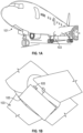
- FIG. 1A and FIG. 1B are schematic illustrations of a conventional aircraft 101.
- the aircraft 101 includes an underside 103.
- the underside 103 can include the cooling system 105.
- the cooling system 105 could be located in other parts of the aircraft.
- the cooling systems herein can provide cooling for a superconducting motor in the range of 20 Kelvins (e.g., at 20 K).
- the fuel option it is most efficient to boil the fuel at a low pressure to provide cooling abilities. As a result of this process, the resulting coolant has high heat transfer coefficients and no temperature rise.
- the liquid fuel can be can be a hydrogen fuel in a liquid for (e.g,. LH 2 ).
- a fuel is typically stored at or about 20 K and, thus, can be applied directly to the superconducting motor.
- the system 200 can be the located as shown by system 105 in Fig. 1 but that is not required.
- the system 200 can include a fuel tank 210 that includes, for example, LH 2 .
- the LH 2 fuel in the fuel tank 210 is at a temperature of 20 K and a pressure of 1 bar in one embodiment.
- the fuel is moved from the LH 2 fuel tank 210 to a combustor 270 through various paths.
- the "main" fuel path is from the tank 210 to the combustor 270 through ejector 250 and then into the combustor 270. As detailed below, this main fuel path can include first and fourth fuel paths 220 and 260.
- the system 200 also includes a cooling path that provides fuel from the tank 210 through a superconducting electric motor 300.
- the system 200 can be either attached to or include the superconducting electric motor 300.
- the cooling path is shown as including the second fuel path 310 which branches from the main fuel path and provides liquid fuel to the superconducting electric motor 300.
- the fuel is then partially or completely vaporized as is passes superconducting electric motor 300.
- the partially or completely vaporized fuel is then provided via a third fuel path 320 back into the main fuel path.
- the third fuel path 320 provides the to a gas/vapor input 295 of the ejector 250.
- the partially or completely vaporized fuel is then mixed with the liquid fuel in the ejector 250 and mixed fuel is provided to combustor 270 via the fourth fuel path 260.
- Additional optional elements are shown in the system 200 that can be used to control certain pressures/temperatures in the system so that it may operate more efficiently. These additional elements are not necessarily required.
- the first path 220 may include the first pump 230, which moves the liquid fuel through the first path 220 by increasing the pressure of the liquid fuel.
- the first path 220 may include additional aircraft loads 240, which may be cooled through the flow of the liquid fuel.
- the fuel further passes from the LH 2 tank 210 through the second fuel path 310.
- the second path 310 may optionally contain a second pump 320, which is used to increase the pressure of the fuel.
- the fuel moves through the superconducting motor 300, cooling the superconducting motor 300 and vaporizing the fuel.
- the vaporized fuel then exits the superconducting motor 300 through the third path 330, which transports the fuel to gas/vapor input 295 of the first two-phase ejector 250.
- the vaporized and liquid fuel are mixed, resulting in a liquid fuel at a pressure appropriate for the combustor 270.
- the fuel must be compressed to a compatible pressure in order to be used by the combustor.
- An appropriate pressure may be between 500 to 1000 psia.
- the first two-phase ejector 250 is used to raise the pressure of the vaporized fuel to that of the combustor.
- the liquid fuel that flows through the first path 220 is pressurized to a pressure higher than that required by the combustor 270, and acts as the primary flow to the two-phase ejector 250 and enters at liquid inlet 285 of the ejector 250.
- the flow of liquid fuel that flows through the first path 220 is accelerated through a convergingdiverging nozzle to supersonic velocities and entrains the low-pressure vapor stream received via third path 330.
- the combined flows of liquid fuel through the first path 220 and vaporized fuel through third path 330 mix in a mixing section 280 followed by a converging diverging diffuser 290, which further recovers the appropriate pressure.
- the pressurized fuel is then transported from the two-phase ejector 250 to the first combustor 270 through the fourth path 260.
- the resulting fuel is received by the combustor 270, which generates rotational energy through the combustion of the liquid fuel, ultimately providing electricity to the superconducting motor 300 as indicated by connection 280.
- the combustor 270 could be part of an engine and could also generate thrust.
- a bio-liquid natural gas (Bio-LNG) fuel can be used to cool a superconducting motor.
- FIG. 3 an example cooling system 400 is shown.
- the system 400 work similar to that shown in FIG. 2 .
- the Bio-LNG may be at a higher temperature than the LH 2 .
- the Bio-LNG is used to provide a cooling or working fluid to the cryocooler.
- the Bio-LNG is vaporized in the cryocooler and then recombined with a liquid Bio-LNG as described above.
- the system 400 includes Bio-LNG fuel tank 410.
- the Bio-LNG fuel in the Bio-LNG fuel tank 410 may be at a temperature of 112 K and a pressure of 1 bar.
- a cryocooler 540 may be used to reduce the temperature of a cooling substance in a cooling loop 550 to 20K.
- the Bio-LNG is used carry heat away from the cryocooler 540.
- the fuel is moved from the Bio-LNG fuel tank 410 to a combustor 470 through various paths.
- the "main" fuel path is from the tank 410 to the combustor 470 through ejector 450 and then into the combustor 470.
- this main fuel path can include paths first and fourth paths 420 and 460.
- the system 400 also includes a cooling path that provides fuel from the tank 410 to be used a cooling source provided to the cryocooler 540.
- the cooling path is shown as including the second fuel path 510 which branches from the main fuel path and provides liquid fuel to the cryocooler 540.
- the fuel is then partially or completely vaporized as is it passes through cryocooler 540.
- the partially or completely vaporized fuel is then provided via a third fuel path 520 back into the main fuel path.
- the third fuel path 520 provides the to a gas/vapor input 295 of the ejector 450.
- the partially or completely vaporized fuel is then mixed with the liquid fuel in the ejector 450 and mixed fuel is provided to combustor 470 via the fourth fuel path 460.
- Additional optional elements are shown in the system 400 that can be used to control certain pressures/temperatures in the system so that it may operate more efficiently. These additional elements are not necessarily required.
- the first path 420 may include the first pump 430, which moves the liquid fuel through the first path 420 by increasing the pressure of the liquid fuel.
- the first path 420 may include additional aircraft loads 440, which may be cooled through the flow of the liquid fuel.
- the fuel further passes from the tank 410 through the second fuel path 510 and is provided through the cryocooler 540.
- a cryocooling loop 550 can be established through the cooling side 545 of the cryocooler 540.
- the cryocooling loop 550 may optionally contain a second pump 530, which is used to increase the pressure of the cooling fluid in the cryocooling loop 550.
- the working/cooling fluid moves through the cryocooler 540 cooling the superconducting motor 500 and carriers heat away from the motor 500.
- the cryocooler 540 removes the heat from cooling fluid in the cryocooling loop 550. This results in the heat being transferred to the Bio-LNG fuel which may be vaporized.
- the cooling fluid can be any suitable working fluid such that can be cooled to a required superconducting temperature.
- An example is LH 2 and the LH 2 can be kept as about 20 K by the cryocooler 540 in one embodiment.
- the working fluid may be chosen from the group consisting of helium, hydrogen, or a mixture of helium and hydrogen.
- the vaporized fuel then exits the cryocooler 540 through third path 330, which transports the fuel to gas/vapor input 295 of the first two-phase ejector 250.
- the vaporized and liquid fuel are mixed, resulting in a liquid fuel at a pressure appropriate for the combustor 470.
- the fuel must be compressed to a compatible pressure in order to be used by the combustor.
- An appropriate pressure may be between 500 to 1000 psia.
- the two-phase ejector 450 is used to raise the pressure of the vaporized fuel to that of the combustor.
- the liquid fuel that flows through the first path 420 is pressurized to a pressure higher than that required by the combustor 470, and acts as the primary flow to the two-phase ejector 450 and enters at liquid inlet 885 of the ejector 250.
- the flow of liquid fuel that flows through the first path 420 is accelerated through a convergingdiverging nozzle to supersonic velocities and entrains the low-pressure vapor stream received via third path 520.
- the combined flows of liquid fuel through the first path 420 and vaporized fuel through third path 520 mix in a first mixing section 280 followed by a first diverging diffuser 290, which further recovers the appropriate pressure.
- the pressurized fuel is then transported from the two-phase ejector 450 to the combustor 470 through fourth path 460.
- the resulting fuel is received by the first combustor 470, which generates rotational energy through the combustion of the liquid fuel, ultimately providing electricity to the first superconducting motor 500 as indicated by connection 480.
- the combustor 470 could be part of an engine and could also generate thrust.
Landscapes
- Engineering & Computer Science (AREA)
- Aviation & Aerospace Engineering (AREA)
- Chemical & Material Sciences (AREA)
- Combustion & Propulsion (AREA)
- Mechanical Engineering (AREA)
- Power Engineering (AREA)
- General Engineering & Computer Science (AREA)
- Filling Or Discharging Of Gas Storage Vessels (AREA)
- Superconductive Dynamoelectric Machines (AREA)
Abstract
A system for cooling a superconducting motor includes a combustor (270) and fuel tank (210) that contains a fuel. The system further includes a cooling system (200) that provides the fuel to the superconducting motor or a cryocooler to cool the superconducting motor, resulting in at least partially vaporized fuel coming out of the superconducting motor or cryocooler. The cooling system also a cryocooler and a twophase ejector that mixes the fuel from the tank and the at least partially vaporized fuel to produce a mixed fuel. The combustor receives the mixed fuel and generates electric power due its combustion. The power can be provided to the superconducting motor.
Description
- This invention was made with Government support under U.S. Government Contract No. DE-AR0001404 awarded by the Department of Energy. The U.S. Government has certain rights in the invention.
- This disclosure relates to cooling electric motors and, more particularly, to a cooling architecture that can use fuel to cool superconducting motors.
- As air travel seeks more sustainable approaches, there has been significant research done on operating aircraft more efficient and, possibly, with sustainable fuels. Further, as aircraft become more electric, the need to improve the operations/efficiency of electric motors has become a source of investigation.
- One approach has been to utilize high efficiency electric motors. An example of motors that may be used are so-called super conducting motors. Such motors include superconducting materials used for the windings therein and can enable high-efficiency and high-power-density aviation class electric motors and drives. However, motors that include superconducting materials need to be cryogenically cooled to temperatures of about 77 °K or less to function properly. For example, to minimize AC losses, superconducting materials such as MgB2 need to be cooled to temperatures in the range of 20 °K.
- A number of approaches are available including cooling architectures including thermal contact to liquefied gases, and cryogenic refrigerators, usually termed cryocoolers.
- Disclosed are one embodiments of systems and method to cool a superconducting motor.
- In one aspect, disclosed is a system for cooling a superconducting motor The system includes: fuel tank that contains a fuel; a combustor that receives the fuel from the fuel tank and generates electric power due to combustion of the fuel and provides the electric power to the superconducting motor; and a cooling system that provides the fuel to the superconducting motor to cool the superconducting motor. The cooling system includes a two-phase ejector that includes a liquid fuel input, a partially or totally vaporized fuel input and an output, a main path that transports fuel from the fuel tank, through the two-phase ejector and to the combustor, wherein the liquid fuel input is fluidly coupled to and receives the liquid fuel from the fuel tank via the main path; and a cooling path that that transports fuel from the fuel tank, through the superconducting motor and to the partially or totally vaporized fuel input of the two-phase ejector. The two-phase ejector mixes the fuel and the at least partially vaporized fuel together to form a fuel stream at the output.
- The fuel in this embodiment or any other embodiment disclosed herein can be LH2.
- In embodiments: the main path includes a first path that transports the liquid fuel from the tank to liquid fuel input; the cooling path includes second path that carries liquid fuel from the tank to the superconducting motor; the cooling path includes a third path that that transports at least partially vaporized fuel away from the superconducting motor to the partially or totally vaporized fuel input; and the main path includes a fourth path that carriers mixed fuel from the output of the two-phase ejector to the combustor.
- In embodiments, a first pump arranged along the first path that increases the pressure of the fuel before it is provided to the two-phase ejector.
- In embodiments, the second path contains a second pump, that increases the pressure of the fuel before it is provided to the superconducting motor.
- In embodiments, the first path passes through other aircraft loads before it provides fuel to the two-phase ejector.
- Also disclosed herein is an embodiment that includes a cryocooler. The cryocooler embodiment is a system for cooling a superconducting motor that includes: a fuel tank that contains a fuel; a combustor that receives the fuel from the fuel tank and generates electrical power due to combustion of the fuel and provides the electric power to the superconducting motor; and a cooling system. In this embodiment, the cooling system includes: a cryocooler to cool the superconducting motor, wherein the cryocooler is arranged to define a cryocooling loop that passes a working fluid through the superconducting motor; a two-phase ejector that includes a liquid fuel input, a partially or totally vaporized fuel input and an output; a main path that transports fuel from the fuel tank, through the two-phase ejector and to the combustor, wherein the liquid fuel input is fluidly coupled to and receives the liquid fuel from the fuel tank via the main path; and a cooling path that that transports fuel from the fuel tank, through the cryocooler and to the partially or totally vaporized fuel input the of the two-phase ejector, wherein the cooling path is arranged such that heat from the working fluid is transferred from the working fluid to the fuel to create at least partially or totally vaporized fuel. The two-phase ejector mixes the fuel and the at least partially vaporized fuel together to form a fuel stream at the output.
- In the cryocooler embodiment, fuel can be Bio-LNG.
- In the cryocooler embodiment, the main path includes a first path that transports the liquid fuel from the tank to liquid fuel input; the cooling path includes second path that carries liquid fuel from the tank to the cryocooler; the cooling path includes a third path that that transports at least partially vaporized fuel away from the cryocooler to the partially or totally vaporized fuel input; and the main path includes a fourth path that carriers mixed fuel from the output of the two-phase ejector to the combustor.
- In the cryocooler embodiment, a first pump can be arranged along the first path that increases the pressure of the fuel before it is provided to the two-phase ejector.
- In the cryocooler embodiment, the second path can contain a second pump, that increases the pressure of the fuel before it is provided to the cryocooler.
- In the cryocooler embodiment, the first path can pass through other aircraft loads before it provides fuel to the two-phase ejector.
- In the cryocooler embodiment, the working fluid is chosen from the group consisting of helium, hydrogen, or a mixture of helium and hydrogen.
- In the cryocooler embodiment, the second path can contain a third pump, that is used to move the fuel.
- In the cryocooler embodiment, the cryocooler can be a sterling cryocooler, a magnetocaloric cryocooler, pulse tube cryocooler, a helium cryocooler, or a polycold cryocooler.
- Also disclosed is a method for cooling a superconducting motor. The method includes: passing fuel from a fuel tank to combustor to generates electric power due to combustion of the fuel; and providing the electric power to the superconducting motor. Passing fuel includes: providing liquid fuel to a fuel a two-phase ejector that includes a liquid fuel input, a partially or totally vaporized fuel input and an output, wherein the liquid fuel is provided to the liquid fuel input via a main path; and providing liquid fuel to a cooling path that that transports fuel from the fuel tank, through the superconducting motor or a cryocooler and to the partially or totally vaporized fuel input of the two-phase ejector, wherein the fuel is partially or totally vaporized by the superconducting motor or the cryocooler. The two-phase ejector mixes the fuel and the at least partially vaporized fuel together to form a fuel stream at the output.
- The method can be performed on any system disclosed herein or variations thereof.
- The following descriptions should not be considered limiting in any way. With reference to the accompanying drawings, like elements are numbered alike:
-
FIG. 1A is a schematic illustration of an aircraft; -
FIG. 1B is a schematic illustration of the belly of an aircraft; -
FIG. 2 is a schematic illustration of the cooling architectures for LH2 fuel; and -
FIG. 3 is a schematic illustration of the cooling architectures for Bio-LNG fuel. - A detailed description of one or more embodiments of the disclosed apparatus and method are presented herein by way of exemplification and not limitation with reference to the Figures.
- Using superconducting materials (and in particular in the windings) in motors/drives of an aircraft allow for high-efficiency and high-power-density aviation class electric motors. However, to function properly, the superconducting materials in these motors/drives need to be cryogenically cooled. Disclosed herein is a system that synergistically uses cryogenic fuel sources that are combusted (to generate either or both thrust and electrical power) to cool superconducting materials in the motors.
- In particular, detailed herein is a cooling system for a superconducting motor. As used herein, a superconducting motor is an electric motor that includes a at least one element formed of superconducting material. In one embodiment, the element is one or more windings of the electric motor.
- The system includes a fuel tank containing a fuel in liquid form. The fuel can be LH2 or Bio-LNG. These fuels are typically kept cold (e.g., cryogenic) temperatures. As more fully described below, the fuels can be used by a combustor in the aircraft and can provide reduced or no emissions. The combustor, that receives the fuel and generates rotational energy (or thrust, or both) through combustion of the fuel. The rotational energy can be used to generate electricity (either by the combustor itself or with a generator) that is then used to drive the superconducting motor.
- As the fuel is cold it can also be used to keep the superconducting element of the motor cooled. Thus, in addition to the fuel tank, the system can include a cooling system or loop that routes the cold fuel through the superconducting motor and, in particular, coils of the superconducting motor to keep them cool. To that end, the cooling system comprises a fuel path that moves the liquid fuel from the tank through the superconducting motor. As the fuel passes through the motor, it absorbs heat and this can result in the fuel being partially or wholly vaporized. In another embodiment, the fuel is used to carry heat away from cryocooler that is used to cool the motor.
- To reclaim the at least partially vaporized fuel, a two-phase ejector is provided. The two phase ejector is provided in the path between the fuel source/tank and the combustor. Via the ejector, the liquid fuel from the tanks serves entrain the vapor so that it can be provided to the combustor. This can result in vapor being converted partially or wholly back into a liquid form in some instances.
- In short, the two-phase ejector serves to mix the vaporized and liquid fuel to form an output fuel which is provided to the combustor. It should be noted that the fuel not need be provided directly to a motor and, rather, can be provided as a cooling (heat removal) source for a cryocooler. In such a case, the fuel is vaporized in the cryocooler and then mixed with the liquid as described above
-
FIG. 1A and FIG. 1B are schematic illustrations of aconventional aircraft 101. As illustrated, theaircraft 101 includes anunderside 103. Theunderside 103 can include thecooling system 105. However, thecooling system 105 could be located in other parts of the aircraft. The cooling systems herein can provide cooling for a superconducting motor in the range of 20 Kelvins (e.g., at 20 K). - Regardless of the fuel option, it is most efficient to boil the fuel at a low pressure to provide cooling abilities. As a result of this process, the resulting coolant has high heat transfer coefficients and no temperature rise.
- In an embodiment, the liquid fuel can be can be a hydrogen fuel in a liquid for (e.g,. LH2). Such a fuel is typically stored at or about 20 K and, thus, can be applied directly to the superconducting motor.
- With reference to
FIG. 2 anexample cooling system 200 is shown. Thesystem 200 can be the located as shown bysystem 105 inFig. 1 but that is not required. - The
system 200 can include afuel tank 210 that includes, for example, LH2. The LH2 fuel in thefuel tank 210 is at a temperature of 20 K and a pressure of 1 bar in one embodiment. The fuel is moved from the LH2 fuel tank 210 to acombustor 270 through various paths. The "main" fuel path is from thetank 210 to thecombustor 270 throughejector 250 and then into thecombustor 270. As detailed below, this main fuel path can include first andfourth fuel paths - The
system 200 also includes a cooling path that provides fuel from thetank 210 through a superconductingelectric motor 300. Thesystem 200 can be either attached to or include the superconductingelectric motor 300. The cooling path is shown as including thesecond fuel path 310 which branches from the main fuel path and provides liquid fuel to the superconductingelectric motor 300. The fuel is then partially or completely vaporized as is passes superconductingelectric motor 300. The partially or completely vaporized fuel is then provided via athird fuel path 320 back into the main fuel path. In particular, thethird fuel path 320 provides the to a gas/vapor input 295 of theejector 250. The partially or completely vaporized fuel is then mixed with the liquid fuel in theejector 250 and mixed fuel is provided tocombustor 270 via thefourth fuel path 260. - Additional optional elements are shown in the
system 200 that can be used to control certain pressures/temperatures in the system so that it may operate more efficiently. These additional elements are not necessarily required. - In particular, the
first path 220 may include thefirst pump 230, which moves the liquid fuel through thefirst path 220 by increasing the pressure of the liquid fuel. Thefirst path 220 may include additional aircraft loads 240, which may be cooled through the flow of the liquid fuel. - To cool the
motor 300, as noted above, the fuel further passes from the LH2 tank 210 through thesecond fuel path 310. Thesecond path 310 may optionally contain asecond pump 320, which is used to increase the pressure of the fuel. The fuel moves through thesuperconducting motor 300, cooling thesuperconducting motor 300 and vaporizing the fuel. The vaporized fuel then exits thesuperconducting motor 300 through thethird path 330, which transports the fuel to gas/vapor input 295 of the first two-phase ejector 250. - Once in the first two-
phase ejector 250 the vaporized and liquid fuel are mixed, resulting in a liquid fuel at a pressure appropriate for thecombustor 270. The fuel must be compressed to a compatible pressure in order to be used by the combustor. An appropriate pressure may be between 500 to 1000 psia. The first two-phase ejector 250 is used to raise the pressure of the vaporized fuel to that of the combustor. - The liquid fuel that flows through the
first path 220 is pressurized to a pressure higher than that required by thecombustor 270, and acts as the primary flow to the two-phase ejector 250 and enters atliquid inlet 285 of theejector 250. The flow of liquid fuel that flows through thefirst path 220 is accelerated through a convergingdiverging nozzle to supersonic velocities and entrains the low-pressure vapor stream received viathird path 330. The combined flows of liquid fuel through thefirst path 220 and vaporized fuel throughthird path 330 mix in amixing section 280 followed by a converging divergingdiffuser 290, which further recovers the appropriate pressure. - The pressurized fuel is then transported from the two-
phase ejector 250 to thefirst combustor 270 through thefourth path 260. The resulting fuel is received by thecombustor 270, which generates rotational energy through the combustion of the liquid fuel, ultimately providing electricity to thesuperconducting motor 300 as indicated byconnection 280. Thecombustor 270 could be part of an engine and could also generate thrust. - In an embodiment, a bio-liquid natural gas (Bio-LNG) fuel can be used to cool a superconducting motor. As illustrated in
FIG. 3 , anexample cooling system 400 is shown. Thesystem 400 work similar to that shown inFIG. 2 . However, the Bio-LNG may be at a higher temperature than the LH2. Thus, rather than using the Bio-LNG to directly cool the superconducting motor, the Bio-LNG is used to provide a cooling or working fluid to the cryocooler. Thus, the Bio-LNG is vaporized in the cryocooler and then recombined with a liquid Bio-LNG as described above. - As shown in
FIG. 3 , thesystem 400 includesBio-LNG fuel tank 410. The Bio-LNG fuel in theBio-LNG fuel tank 410 may be at a temperature of 112 K and a pressure of 1 bar. - A
cryocooler 540 may be used to reduce the temperature of a cooling substance in acooling loop 550 to 20K. In such a case, the Bio-LNG is used carry heat away from thecryocooler 540. - The fuel is moved from the
Bio-LNG fuel tank 410 to acombustor 470 through various paths. The "main" fuel path is from thetank 410 to thecombustor 470 throughejector 450 and then into thecombustor 470. As detailed below, this main fuel path can include paths first andfourth paths - The
system 400 also includes a cooling path that provides fuel from thetank 410 to be used a cooling source provided to thecryocooler 540. The cooling path is shown as including thesecond fuel path 510 which branches from the main fuel path and provides liquid fuel to thecryocooler 540. The fuel is then partially or completely vaporized as is it passes throughcryocooler 540. The partially or completely vaporized fuel is then provided via athird fuel path 520 back into the main fuel path. In particular, thethird fuel path 520 provides the to a gas/vapor input 295 of theejector 450. The partially or completely vaporized fuel is then mixed with the liquid fuel in theejector 450 and mixed fuel is provided tocombustor 470 via thefourth fuel path 460. - Additional optional elements are shown in the
system 400 that can be used to control certain pressures/temperatures in the system so that it may operate more efficiently. These additional elements are not necessarily required. - In particular, the
first path 420 may include thefirst pump 430, which moves the liquid fuel through thefirst path 420 by increasing the pressure of the liquid fuel. Thefirst path 420 may include additional aircraft loads 440, which may be cooled through the flow of the liquid fuel. - To cool the
motor 500, as noted above, the fuel further passes from thetank 410 through thesecond fuel path 510 and is provided through thecryocooler 540. Acryocooling loop 550 can be established through thecooling side 545 of thecryocooler 540. - The
cryocooling loop 550 may optionally contain asecond pump 530, which is used to increase the pressure of the cooling fluid in thecryocooling loop 550. The working/cooling fluid moves through thecryocooler 540 cooling thesuperconducting motor 500 and carriers heat away from themotor 500. Thecryocooler 540 removes the heat from cooling fluid in thecryocooling loop 550. This results in the heat being transferred to the Bio-LNG fuel which may be vaporized. The cooling fluid can be any suitable working fluid such that can be cooled to a required superconducting temperature. An example is LH2 and the LH2 can be kept as about 20 K by thecryocooler 540 in one embodiment. Further, the working fluid may be chosen from the group consisting of helium, hydrogen, or a mixture of helium and hydrogen. - The vaporized fuel then exits the
cryocooler 540 throughthird path 330, which transports the fuel to gas/vapor input 295 of the first two-phase ejector 250. - Once in the first two-
phase ejector 450 the vaporized and liquid fuel are mixed, resulting in a liquid fuel at a pressure appropriate for thecombustor 470. The fuel must be compressed to a compatible pressure in order to be used by the combustor. An appropriate pressure may be between 500 to 1000 psia. The two-phase ejector 450 is used to raise the pressure of the vaporized fuel to that of the combustor. - The liquid fuel that flows through the
first path 420 is pressurized to a pressure higher than that required by thecombustor 470, and acts as the primary flow to the two-phase ejector 450 and enters at liquid inlet 885 of theejector 250. The flow of liquid fuel that flows through thefirst path 420 is accelerated through a convergingdiverging nozzle to supersonic velocities and entrains the low-pressure vapor stream received viathird path 520. The combined flows of liquid fuel through thefirst path 420 and vaporized fuel throughthird path 520 mix in afirst mixing section 280 followed by a first divergingdiffuser 290, which further recovers the appropriate pressure. - The pressurized fuel is then transported from the two-
phase ejector 450 to thecombustor 470 throughfourth path 460. The resulting fuel is received by thefirst combustor 470, which generates rotational energy through the combustion of the liquid fuel, ultimately providing electricity to thefirst superconducting motor 500 as indicated byconnection 480. Thecombustor 470 could be part of an engine and could also generate thrust. - The term "about" is intended to include the degree of error associated with measurement of the particular quantity based upon the equipment available at the time of filing the application.
- The terminology used herein is for the purpose of describing particular embodiments only and is not intended to be limiting of the present disclosure. As used herein, the singular forms "a", "an" and "the" are intended to include the plural forms as well, unless the context clearly indicates otherwise. It will be further understood that the terms "comprises" and/or "comprising," when used in this specification, specify the presence of stated features, integers, steps, operations, elements, and/or components, but do not preclude the presence or addition of one or more other features, integers, steps, operations, element components, and/or groups thereof.
- While the present disclosure has been described with reference to an exemplary embodiment or embodiments, it will be understood by those skilled in the art that various changes may be made without departing from the scope of the invention as defined by the claims. In addition, many modifications may be made to adapt a particular situation or material to the teachings of the present disclosure without departing from the scope of the claims. Therefore, it is intended that the present disclosure not be limited to the particular embodiment disclosed as the best mode contemplated for carrying out this present disclosure, but that the present disclosure will include all embodiments falling within the scope of the claims.
Claims (15)
- A system for cooling a superconducting motor, the system comprising:a fuel tank (210) that contains a fuel;a combustor (270) that receives the fuel from the fuel tank and generates electric power due to combustion of the fuel and provides the electric power to the superconducting motor; anda cooling system (200) that provides the fuel to the superconducting motor to cool the superconducting motor, the cooling system comprising:a two-phase ejector (250) that includes a liquid fuel input, a partially or totally vaporized fuel input and an output;a main path that transports fuel from the fuel tank, through the two-phase ejector and to the combustor, wherein the liquid fuel input is fluidly coupled to and receives the liquid fuel from the fuel tank via the main path;a cooling path that that transports fuel from the fuel tank, through the superconducting motor and to the partially or totally vaporized fuel input of the two-phase ejector;wherein the two-phase ejector mixes the fuel and the at least partially vaporized fuel together to form a fuel stream at the output.
- The system of claim 1, wherein the fuel is LH2.
- The system of claim 1 or 2, wherein:the main path includes a first path that transports the liquid fuel from the tank to liquid fuel input;the cooling path includes second path that carries liquid fuel from the tank to the superconducting motor;the cooling path includes a third path that that transports at least partially vaporized fuel away from the superconducting motor to the partially or totally vaporized fuel input; andthe main path includes a fourth path that carriers mixed fuel from the output of the two-phase ejector to the combustor.
- The system of claim 3, further comprising:
a first pump (230) arranged along the first path that increases the pressure of the fuel before it is provided to the two-phase ejector. - The system of claim 4, wherein the second path contains a second pump (530), that increases the pressure of the fuel before it is provided to the superconducting motor.
- The system of claim 1, wherein the cooling system further comprises:
a cryocooler (540) to cool the superconducting motor, wherein the cryocooler is arranged to define a cryocooling loop that passes a working fluid through the superconducting motor; and wherein thecooling path transports fuel from the fuel tank, through the cryocooler and to the partially or totally vaporized fuel input the of the two-phase ejector, wherein the cooling path is arranged such that heat from the working fluid is transferred from the working fluid to the fuel to create the at least partially or totally vaporized fuel. - The system of claim 6, wherein the fuel is Bio-LNG.
- The system of claim 6 or 7, wherein:the main path includes a first path that transports the liquid fuel from the tank to liquid fuel input;the cooling path includes second path that carries liquid fuel from the tank to the cryocooler;the cooling path includes a third path that that transports at least partially vaporized fuel away from the cryocooler to the partially or totally vaporized fuel input; andthe main path includes a fourth path that carriers mixed fuel from the output of the two-phase ejector to the combustor.
- The system of claim 8, further comprising:
a first pump arranged along the first path that increases the pressure of the fuel before it is provided to the two-phase ejector, and optionally wherein the second path contains a second pump, that increases the pressure of the fuel before it is provided to the cryocooler. - The system of any of claims 6 to 9 wherein the working fluid is chosen from the group consisting of helium, hydrogen, or a mixture of helium and hydrogen.
- The system of claim 8, wherein the second path contains a third pump, that is used to move the fuel.
- The system of and of claims 6 to 11, wherein the cryocooler is a sterling cryocooler, a magnetocaloric cryocooler, pulse tube cryocooler, a helium cryocooler, or a polycold cryocooler.
- The system of any preceding claim, wherein the first path passes through other aircraft loads before it provides fuel to the two-phase ejector.
- A method for cooling a superconducting motor, the system comprising:passing fuel from a fuel tank to combustor to generates electric power due to combustion of the fuel;providing the electric power to the superconducting motor;wherein passing fuel includes:providing liquid fuel to a fuel a two-phase ejector that includes a liquid fuel input, a partially or totally vaporized fuel input and an output, wherein the liquid fuel is provided to the liquid fuel input via a main path;providing liquid fuel to a cooling path that that transports fuel from the fuel tank, through the superconducting motor or a cryocooler and to the partially or totally vaporized fuel input of the two-phase ejector, wherein the fuel is partially or totally vaporized by the superconducting motor or the cryocooler;wherein the two-phase ejector mixes the fuel and the at least partially vaporized fuel together to form a fuel stream at the output.
- The method of claim 14, wherein the fuel is LH2, and optionally, wherein:the main path includes a first path that transports the liquid fuel from the tank to liquid fuel input;the cooling path includes second path that carrier liquid fuel from the tank to the superconducting motor;the cooling path includes a third path that that transports at least partially vaporized fuel away from the superconducting motor to the partially or totally vaporized fuel input; andthe main path includes a fourth path that carriers mixed fuel from the output of the two-phase ejector to the combustor; orwherein the fuel is Bio-LNG, and optionally wherein:the main path includes a first path that transports the liquid fuel from the tank to liquid fuel input;the cooling path includes second path that carries liquid fuel from the tank to the cryocooler;the cooling path includes a third path that that transports at least partially vaporized fuel away from the cryocooler to the partially or totally vaporized fuel input; andthe main path includes a fourth path that carriers mixed fuel from the output of the two-phase ejector to the combustor.
Applications Claiming Priority (1)
| Application Number | Priority Date | Filing Date | Title |
|---|---|---|---|
| US18/146,001 US12428166B2 (en) | 2022-12-23 | 2022-12-23 | Cooling architecture using cryogenic fuels |
Publications (1)
| Publication Number | Publication Date |
|---|---|
| EP4389606A1 true EP4389606A1 (en) | 2024-06-26 |
Family
ID=88506683
Family Applications (1)
| Application Number | Title | Priority Date | Filing Date |
|---|---|---|---|
| EP23204968.4A Pending EP4389606A1 (en) | 2022-12-23 | 2023-10-20 | Cooling architecture using cryogenic fuels |
Country Status (2)
| Country | Link |
|---|---|
| US (1) | US12428166B2 (en) |
| EP (1) | EP4389606A1 (en) |
Families Citing this family (1)
| Publication number | Priority date | Publication date | Assignee | Title |
|---|---|---|---|---|
| US12331687B1 (en) * | 2024-08-02 | 2025-06-17 | Rtx Corporation | Cryogenic fuel semi-closed injection cooled bottoming cycle |
Citations (3)
| Publication number | Priority date | Publication date | Assignee | Title |
|---|---|---|---|---|
| US20200047908A1 (en) * | 2016-10-11 | 2020-02-13 | Siemens Aktiengesellschaft | Drive System For a Vehicle with an Internal Combustion Engine and Fuel Tank |
| GB2587556A (en) * | 2018-10-15 | 2021-03-31 | Gkn Aerospace Services Ltd | Apparatus |
| EP3904218A1 (en) * | 2020-05-01 | 2021-11-03 | Hamilton Sundstrand Corporation | Catalytic fuel tank inerting systems |
Family Cites Families (15)
| Publication number | Priority date | Publication date | Assignee | Title |
|---|---|---|---|---|
| BE508930A (en) * | 1951-02-10 | |||
| US5275000A (en) * | 1992-08-17 | 1994-01-04 | General Electric Company | Reducing thermal deposits in endothermic fuel reactors of propulsion systems |
| US6553773B2 (en) | 2001-05-15 | 2003-04-29 | General Electric Company | Cryogenic cooling system for rotor having a high temperature super-conducting field winding |
| US6442949B1 (en) | 2001-07-12 | 2002-09-03 | General Electric Company | Cryongenic cooling refrigeration system and method having open-loop short term cooling for a superconducting machine |
| US6438969B1 (en) | 2001-07-12 | 2002-08-27 | General Electric Company | Cryogenic cooling refrigeration system for rotor having a high temperature super-conducting field winding and method |
| WO2007001432A2 (en) | 2004-11-12 | 2007-01-04 | Praxair Technology, Inc. | Hydrogen cooling system for superconducting equipment |
| US20130186097A1 (en) * | 2012-01-23 | 2013-07-25 | General Electric Company | Liquid Fuel Heating System |
| US9261295B1 (en) | 2012-03-26 | 2016-02-16 | Ball Aerospace & Technologies Corp. | Hybrid liquid-hydrogen and helium cryocooler systems and methods |
| KR20150061276A (en) | 2013-11-27 | 2015-06-04 | 대우조선해양 주식회사 | Cooling system for superconductor |
| US10215097B2 (en) * | 2015-12-08 | 2019-02-26 | General Electric Company | Thermal management system |
| US10465609B2 (en) * | 2015-12-18 | 2019-11-05 | Pratt & Whitney Canada Corp. | Engine fuel system for use with composite aircraft |
| US11041439B2 (en) | 2018-09-14 | 2021-06-22 | Raytheon Technologies Corporation | Hybrid expander cycle with turbo-generator and cooled power electronics |
| GB2578288B (en) | 2018-10-15 | 2022-04-13 | Gkn Aerospace Services Ltd | Apparatus |
| FR3110895B1 (en) | 2020-05-28 | 2022-06-24 | Safran | Aircraft hybrid propulsion system |
| EP4265897B1 (en) * | 2022-04-22 | 2025-09-24 | Eaton Intelligent Power Limited | Hydrogen fuel system for aircraft |
-
2022
- 2022-12-23 US US18/146,001 patent/US12428166B2/en active Active
-
2023
- 2023-10-20 EP EP23204968.4A patent/EP4389606A1/en active Pending
Patent Citations (3)
| Publication number | Priority date | Publication date | Assignee | Title |
|---|---|---|---|---|
| US20200047908A1 (en) * | 2016-10-11 | 2020-02-13 | Siemens Aktiengesellschaft | Drive System For a Vehicle with an Internal Combustion Engine and Fuel Tank |
| GB2587556A (en) * | 2018-10-15 | 2021-03-31 | Gkn Aerospace Services Ltd | Apparatus |
| EP3904218A1 (en) * | 2020-05-01 | 2021-11-03 | Hamilton Sundstrand Corporation | Catalytic fuel tank inerting systems |
Also Published As
| Publication number | Publication date |
|---|---|
| US12428166B2 (en) | 2025-09-30 |
| US20240208661A1 (en) | 2024-06-27 |
Similar Documents
| Publication | Publication Date | Title |
|---|---|---|
| US11603798B1 (en) | Cryogenically assisted exhaust condensation | |
| EP3623603B1 (en) | Hybrid expander cycle with turbo-generator and cooled power electronics | |
| US5048597A (en) | Leak-safe hydrogen/air heat exchanger in an ACE system | |
| US20120096869A1 (en) | Utilizing heat discarded from a gas turbine engine | |
| CN110398131B (en) | An ejector-type cold energy recovery cryogenic cooling device | |
| EP4471262A1 (en) | Aircraft propulsion system with cooling architecture for liquid hydrogen superconducting system | |
| CN109026444B (en) | combined engine | |
| US12270333B2 (en) | Partial exhaust gas condensation with inverse Brayton control | |
| EP4389606A1 (en) | Cooling architecture using cryogenic fuels | |
| CN106894918A (en) | A kind of mode pre-cooling cycle system suitable for assembly power cycle engine | |
| EP4481172A1 (en) | Cryogenic air separation enhanced gas turbine | |
| US11862781B1 (en) | Auxiliary power generation and cooling systems on liquid hydrogen fueled aircraft | |
| US20240369015A1 (en) | Cryogenic bottoming cycle utilizing a thermal bus with multiple heat sources | |
| US11845562B1 (en) | Auxiliary power generation and cooling systems on liquid hydrogen fueled aircraft | |
| WO2007001432A2 (en) | Hydrogen cooling system for superconducting equipment | |
| US20070240451A1 (en) | Integration of IGCC plant with superconducting power island | |
| EP4678890A1 (en) | Stacked cryogenic bottoming cycles | |
| US20240118004A1 (en) | Cryocooler with transient thermal storage | |
| US20240359814A1 (en) | Stacked cryogenic bottoming cycles | |
| US12614740B2 (en) | Auxiliary power generation and cooling systems on liquid hydrogen fueled aircraft | |
| US12221924B2 (en) | Combined gas turbine engine and fuel cell | |
| CN119408719B (en) | A superconducting hydrogen-electric propulsion aircraft thermal management system and working method | |
| CN116379707B (en) | Film type containment system insulating layer cryogenic reliquefaction system and ship | |
| EP4678896A1 (en) | Cryogenic bottoming cycle utilizing a thermal bus with multiple heat sources | |
| Lebrun | Cryogenics and the use of superfluid helium in high-energy particle accelerators (1980-2000) |
Legal Events
| Date | Code | Title | Description |
|---|---|---|---|
| PUAI | Public reference made under article 153(3) epc to a published international application that has entered the european phase |
Free format text: ORIGINAL CODE: 0009012 |
|
| STAA | Information on the status of an ep patent application or granted ep patent |
Free format text: STATUS: THE APPLICATION HAS BEEN PUBLISHED |
|
| AK | Designated contracting states |
Kind code of ref document: A1 Designated state(s): AL AT BE BG CH CY CZ DE DK EE ES FI FR GB GR HR HU IE IS IT LI LT LU LV MC ME MK MT NL NO PL PT RO RS SE SI SK SM TR |
|
| STAA | Information on the status of an ep patent application or granted ep patent |
Free format text: STATUS: REQUEST FOR EXAMINATION WAS MADE |
|
| 17P | Request for examination filed |
Effective date: 20241227 |