EP4389592A1 - An aircraft door with an adjustment system for adjusting the position of the door leaf relative to the door frame - Google Patents
An aircraft door with an adjustment system for adjusting the position of the door leaf relative to the door frame Download PDFInfo
- Publication number
- EP4389592A1 EP4389592A1 EP22214699.5A EP22214699A EP4389592A1 EP 4389592 A1 EP4389592 A1 EP 4389592A1 EP 22214699 A EP22214699 A EP 22214699A EP 4389592 A1 EP4389592 A1 EP 4389592A1
- Authority
- EP
- European Patent Office
- Prior art keywords
- adjustment
- axis
- door
- fork
- door frame
- Prior art date
- Legal status (The legal status is an assumption and is not a legal conclusion. Google has not performed a legal analysis and makes no representation as to the accuracy of the status listed.)
- Granted
Links
Images



Classifications
-
- B—PERFORMING OPERATIONS; TRANSPORTING
- B64—AIRCRAFT; AVIATION; COSMONAUTICS
- B64C—AEROPLANES; HELICOPTERS
- B64C1/00—Fuselages; Constructional features common to fuselages, wings, stabilising surfaces or the like
- B64C1/14—Windows; Doors; Hatch covers or access panels; Surrounding frame structures; Canopies; Windscreens accessories therefor, e.g. pressure sensors, water deflectors, hinges, seals, handles, latches, windscreen wipers
- B64C1/1407—Doors; surrounding frames
- B64C1/1423—Passenger doors
- B64C1/143—Passenger doors of the plug type
-
- E—FIXED CONSTRUCTIONS
- E05—LOCKS; KEYS; WINDOW OR DOOR FITTINGS; SAFES
- E05D—HINGES OR SUSPENSION DEVICES FOR DOORS, WINDOWS OR WINGS
- E05D15/00—Suspension arrangements for wings
-
- B—PERFORMING OPERATIONS; TRANSPORTING
- B64—AIRCRAFT; AVIATION; COSMONAUTICS
- B64C—AEROPLANES; HELICOPTERS
- B64C1/00—Fuselages; Constructional features common to fuselages, wings, stabilising surfaces or the like
- B64C1/14—Windows; Doors; Hatch covers or access panels; Surrounding frame structures; Canopies; Windscreens accessories therefor, e.g. pressure sensors, water deflectors, hinges, seals, handles, latches, windscreen wipers
- B64C1/1407—Doors; surrounding frames
- B64C1/1461—Structures of doors or surrounding frames
Definitions
- the present embodiments relate to an aircraft door, and, more particularly, to an aircraft door with an adjustment system for adjusting the position of the door leaf relative to the door frame.
- the present embodiments further relate to a method of operating such an aircraft door.
- Doors and hatches are movable barriers that close an opening in a boundary between two environments and provide time-limited access between these two environments. Doors and hatches can be found in many technical applications. Examples for such applications include doors and hatches in aircraft, spacecraft, submarines, trains, vehicles, etc.
- a door leaf of an aircraft door In the closed position, a door leaf of an aircraft door needs to be adjusted relative to its opening (i.e., the door frame) in the aircraft's fuselage. This adjustment is necessary to compensate for tolerances of the complex assembly of the door leaf and the door frame, to optimize the opening motion of the door leaf, and to optimize the position of the door leaf relative to the door frame in the closed position during flight due to aerodynamic reasons.
- an aircraft door consists of a door leaf, a door frame, and a support arm.
- the support arm is rotatably mounted to the door frame, and rotatably mounted to the door leaf.
- the door leaf - support arm connection is mounted rotatably around two axes, the vertical aircraft axis and the longitudinal aircraft axis.
- the rotatably mounted support arm is adjustably arranged on the door leaf and the door frame.
- Document EP 3 983 288 A1 describes an aircraft door comprising a support arm connected to a support forearm by a first pivot connection about a first pivot axis, the support forearm being connected to the leaf by a second pivot connection about a second pivot axis parallel to the first pivot axis.
- the support arm is connected to the door frame by two hinges each comprising a pivot for rotating the support arm about a third pivot axis which is parallel to the first pivot axis and to the second pivot axis, this pivot being connected to the door frame by an attachment that is translatably adjustable in two directions orthogonal to one another and orthogonal to the third pivot axis.
- the rotary section is tightened against the shoe by means of the lock nut and is thus supported without play.
- the fork-shaped inner element and the central element and thus the door leaf and the support arm need to be disconnected.
- the door leaf needs to be lifted by a separate unit to ensure a force free connection between door leaf and support arm that enable the removal of a horizontal axle such that washers can be removed or added between the fork-shaped inner element and the central elements.
- the separate unit After reconnecting the fork-shaped inner element with the central element, the separate unit is removed and the position of the door leaf relative to the door frame has to be checked. If the position of the door leaf relative to the door frame is still unsatisfactory, the position can be adjusted in additional iterative staggered loops. This adjustment procedure is obviously time-consuming.
- the horizontal axle is usually designed as a bolt which is clamping the washers and the central element by sleeves. This means that the bolt and the central element have no axial fixation during the adjustment, which can result in unexpected wear between the central element and the horizontal axle.
- an aircraft door for closing an opening in a fuselage of an aircraft in a closed position and for providing access to the aircraft through the opening in the fuselage in a fully open position, comprises a door frame with a door frame bracket, a door leaf with stiffening structures, a support arm assembly with first and second fork-shaped ends, and first and second connecting elements.
- the first connecting element connects the first fork-shaped end of the support arm assembly with the stiffening structures and comprises a first adjustment unit that is adapted for adjusting the position of the door leaf relative to the door frame along a first axis.
- the second connecting element connects the second fork-shaped end of the support arm assembly with the door frame bracket and comprises a second adjustment unit that is adapted for adjusting the position of the door leaf relative to the door frame along a second axis that is perpendicular to the first axis.
- the adjustment of the door leaf in longitudinal direction (i.e., x-direction or between front and aft) of the aircraft and/or in vertical direction (i.e., z-direction or between bottom and top) of the aircraft can be performed decentralized at a location that is apart from the root of the support beam at the mounting on the door frame.
- Placing the adjustment units at a location apart from the root of the support beam at the mounting on the door frame has the advantage that the adjustment devices (screws, bolts, brackets etc..) for the adjustment units can be designed light-weight, because the adjustment units avoid carrying the whole weight of the door leaf.
- the location of the adjustment sleeve for the adjustment along the second axis (z-axis or vertical direction of the aircraft) on the upper side of the support arm connection at the door frame makes the adjustment unit easy to reach for performing the adjustment.
- the securing element and the adjustment unit are both located on the same side, thereby improving the accessibility of the adjustment unit for performing the adjustment process. This results in a simplified and less time-consuming adjustment process.
- the fork-shaped ends of the support arm assembly help to reduce the forces and/or loads in the rotation bearings, resulting in lower frictional forces and therefore less wear and increased service life.
- An additional gliding element may ease the turning of the adjustment sleeve.
- the present technology reduces the adjustment effort as lifting of the door leaf during the adjustment, a disassemble-assemble procedure of the door leaf-support arm connection during adjustment, as well as adjustment iteration loops are avoided such that the result of the adjustment along the first and second axes with the adjustment units is immediately visible.
- the present technology ensures damage free parts during the adjustment process, less loose parts, less wear, and no play during door operation, and a play-free adjustment. Moreover, the present technology improves the adjustment process by providing for a stepless adjustment and an improved accessibility of the adjustment unit.
- the first connecting element further comprises a central element that extends parallel to the second axis between at least two prongs of the first fork-shaped end of the support arm assembly, wherein the central element is rotatably attached to the at least two prongs of the first fork-shaped end of the support arm assembly.
- the first connecting element further comprises a fork-shaped inner element that is attached to the stiffening structures.
- the first adjustment unit further comprises an adjustment axle that extends parallel to the first axis through at least two prongs of the fork-shaped inner element, and a fixation element that rigidly attaches the adjustment axle to the central element.
- the first adjustment unit further comprises at least one socket that is rotatably attached to the adjustment axle.
- the fork-shaped inner element has inner threads and the first adjustment unit further comprises at least one adjustment element that is rigidly attached with the at least one socket, wherein the at least one adjustment element has an outer thread that is adapted for engaging with at least one of the inner threads of the fork-shaped inner element such that a rotation of the at least one adjustment element moves the fork-shaped inner element relative to the adjustment axle along the first axis, thereby adjusting the position of the door leaf relative to the door frame along the first axis.
- the first adjustment unit is arranged in the center of the door leaf.
- the second adjustment unit further comprises a central element that is attached to the door frame bracket.
- the second adjustment unit further comprises an adjustment axle that extends parallel to the second axis through at least two prongs of the second fork-shaped end of the support arm assembly, and first and second clamping sleeves that attach the adjustment axle to the central element and prevent a movement of the adjustment axle relative to the central element along the second axis.
- At least one of the at least two prongs of the second fork-shaped end has an inner thread and the second adjustment unit further comprises an adjustment sleeve with an outer thread that is rotatably mounted to one of the first and second clamping sleeves to prevent a movement of the adjustment sleeve relative to the adjustment axle along the second axis, wherein the outer thread is adapted for engaging with the at least one of the at least two prongs of the second fork-shaped end that has the inner thread such that a rotation of the adjustment sleeve moves the adjustment axle along the second axis, thereby adjusting the position of the door leaf relative to the door frame along the second axis.
- the second adjustment unit further comprises at least one securing element that is adapted for preventing a rotation of the adjustment sleeve.
- a method of operating the above-described aircraft door to adjust the position of the door leaf relative to the door frame comprises rotating at least one adjustment element of the first adjustment unit in a first predetermined rotation direction around the first axis to move the position of the door leaf relative to the door frame along the first axis in a first direction, and rotating the at least one adjustment element of the first adjustment unit in a second predetermined rotation direction that is opposite the first predetermined rotation direction around the first axis to move the position of the door leaf relative to the door frame along the first axis in a second direction that is opposite the first direction.
- the method further comprises rotating the adjustment sleeve of the second adjustment unit in a third predetermined rotation direction around the second axis to move the position of the door leaf relative to the door frame along the second axis in a third direction, and rotating the adjustment sleeve of the second adjustment unit in a fourth predetermined rotation direction that is opposite the third predetermined rotation direction around the second axis to move the position of the door leaf relative to the door frame along the second axis in a fourth direction that is opposite the third direction.
- Exemplary embodiments may be used with any door or hatch that closes a boundary between two environments.
- exemplary embodiments may be used with any vehicle having a door or hatch.
- the door or hatch closes an outside boundary of the vehicle, whereby the door or hatch provides access to the interior of the vehicle from the outside of the vehicle.
- Examples for vehicles may include aircraft such as airplanes, quadcopters, helicopters, and drones, land-based vehicles including cars, buses, trucks, and motorcycles, or vessels such as ships and boats, etc.
- FIG. 1 shows an aircraft 100 with an aircraft airframe 102, which is sometimes also referred to as fuselage 102.
- the aircraft 100 comprises a passenger cabin 103a, a cargo deck 103b, and a flight deck or cockpit 103c.
- the aircraft 100 is accessible via a plurality of aircraft doors 104, which exemplarily comprises several cabin access doors 104a, 104b, 104c, and 104d, as well as one or more cargo deck access doors 104e.
- the passenger cabin 103a and the flight deck 103c are accessible via the cabin access doors 104a, 104b, 104c and 104d
- the cargo deck 103b is accessible via the one or more cargo deck access doors 104e.
- each aircraft door of the plurality of aircraft doors 104 may be adapted for closing an opening in the fuselage 102 of the aircraft 100 in a closed position, thereby preventing access from outside the aircraft 100, and for providing access to the aircraft 100 through the opening in the fuselage 102 (e.g., to the aircraft passenger cabin 103a, the aircraft cargo deck 103b, and/or the aircraft flight deck 103c) in a fully open position.
- At least one of the plurality of aircraft doors 104 is a swiveling aircraft door that closes the opening in the fuselage 102 in a fluid-tight manner.
- At least one aircraft door of the plurality of aircraft doors 104 includes a door frame, a door leaf, a support arm assembly, and first and second connecting elements that connect the support arm assembly with the door leaf and the door frame, respectively.
- aircraft 100 is embodied by an airplane.
- the present embodiments are not limited to airplanes. Instead, any door that closes a boundary between two environments is likewise contemplated.
- the present door may alternatively be applied to other aircrafts such as helicopters, drones, multicopters, etc., to other vehicles such as ships, spacecrafts, submarines, and so on.
- the present door is not limited to aircraft doors, but can likewise be applied to any arbitrary door that closes a boundary between two environments. However, for purposes of illustration, the present door is hereinafter described with respect to aircraft doors.
- the x-axis refers to the longitudinal axis of the aircraft 100 that extends through the front and the aft of the aircraft
- the y-axis refers to the transversal axis of the aircraft 100 that extends through the starboard side and the port side of the aircraft 100
- the z-axis refers to the vertical axis of the aircraft 100 that extends through the bottom and the top of the aircraft 100.
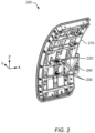
- Figure 2 is a diagram of an illustrative aircraft door 200 with adjustment units 230, 240 that are adapted for adjusting the position of the door leaf 210 relative to the door frame.
- the aircraft door 200 has a door leaf 210 with stiffening structures.
- the stiffening structures may be beam-like or truss-like. If desired, the stiffening structures may have an I-shaped, H-shaped, U-shaped, or T-shaped cross section, any combination thereof, or any other shape that is suitable to reinforce the door leaf 210.
- the aircraft door 200 has a support arm assembly 220 and first and second connecting elements.
- the first connecting element connects the support arm assembly 220 with the stiffening structures of the door leaf 210 and the second connecting element connects the support arm assembly 220 with the door frame.
- the support arm assembly 220 may have a first fork-shaped end, and the first connecting element may connect the first fork-shaped end of the support arm assembly 220 with the stiffening structures.
- the support arm assembly 220 may have a second fork-shaped end, and the second connecting element may connect the second fork-shaped end of the support arm assembly 220 with a door frame bracket of the door frame.
- the first connecting element includes a first adjustment unit that is adapted for adjusting the position of the door leaf 210 relative to the door frame along a first axis (e.g., the x-axis).
- the first adjustment unit may be arranged in the center of the door leaf and is described in more detail with reference to Figure 3 , Figure 4 , and Figure 5 .
- the second connecting element includes a second adjustment unit that is adapted for adjusting the position of the door leaf 210 relative to the door frame along a second axis (e.g., the z-axis).
- the second adjustment unit is described in more detail below with reference to Figure 6 and Figure 7 .
- Figure 3 is a diagram of an illustrative first adjustment unit 300 that is adapted for adjusting the position of the door leaf relative to the door frame along a first axis (i.e., the x-axis) seen from a first perspective.
- the first perspective may be from above the aircraft door (i.e., in negative z-direction).
- the first adjustment unit 300 is adapted for enabling a continuous adjustment of the position of the door leaf 210 relative to the door frame.
- the adjustment unit 300 may enable a stepless adjustment of the position of the door leaf 210 relative to the door frame.
- the door leaf 210 may have stiffening structures 370, and the support arm assembly 220 may have a first fork-shaped end 390.
- the aircraft door may include a first connecting element 380 that connects the first fork-shaped end 390 of the support arm assembly 220 with the stiffening structures 370 of the door leaf 210.
- the first connecting element 380 may include a central element 320.
- the central element 320 may extend parallel to the second axis (i.e., along the z-axis) between at least two prongs of the first fork-shaped end 390 of the support arm assembly 220.
- the central element 320 is rotatably attached to the at least two prongs of the first fork-shaped end 390 of the support arm assembly 220.
- the first connecting element 380 may include an inner element 360 that is attached to the stiffening structures 370.
- the inner element 360 may be a fork-shaped inner element 360.
- the fork-shaped inner element 360 may have at least two prongs.
- the fork-shaped inner element 360 may have three, four, five, six, or more prongs.
- the fork-shaped inner element 360 may have two prongs.
- the first adjustment unit 300 of the first connecting element 380 may include an adjustment axle 310.
- the adjustment axle 310 may extend parallel to the first axis (i.e., along the x-axis) through at least two prongs of the at least two prongs of the fork-shaped inner element 360.
- the at least two prongs of the at least two prongs of the fork-shaped inner element 360, through which the adjustment axle 310 extends, may have inner threads.
- the first adjustment unit 300 may include a fixation element 330.
- the fixation element 330 may rigidly attach the adjustment axle 310 to the central element 320.
- the fixation element 330 may be a pin, a bolt, or a rivet that rigidly attaches the adjustment axle 310 to the central element 320.
- the first adjustment unit 300 may include at least one adjustment element 340. As shown in Figure 3 , the first adjustment unit 300 includes two adjustment elements 340 that are rotatably mounted to the adjustment axle 310 at two opposite sides of the central element 320.
- the at least one adjustment element 340 has an outer thread.
- each one of the at least one adjustment element 340 may be a threaded sleeve.
- the outer thread of the at least one adjustment element 340 is adapted for engaging with a corresponding at least one of the inner threads of the fork-shaped inner element 360.
- a rotation of the at least one adjustment element 340 may move the fork-shaped inner element 360 relative to the adjustment axle 310 along the first axis (i.e., the x-axis), thereby adjusting the position of the door leaf 210 relative to the door frame along the first axis (i.e., the x-axis).
- the at least one adjustment element 340 may be rotated as long as a contact surface (e.g., a bush flange or a lining coating) of the at least one adjustment element 340 is in contact with the central element 320.
- a contact surface e.g., a bush flange or a lining coating
- the at least one adjustment element 340 may be counter-rotated on the adjustment axle 310 to move the door leaf 210 relative to the support arm assembly 220.
- the first adjustment unit 300 may include at least one securing element 350.
- the at least one securing element may be adapted for preventing a rotation of the at least one adjustment element 340.
- the securing element 350 may secure the at least one adjustment element 340 against rotation.
- the securing element 350 may hold the head of the at least one adjustment element 340.
- the at least one adjustment element 340 may have a hexagonal head, a polygonal head, a drilling hole for wire securing or other means that the securing element 350 may use for preventing a rotation of the at least one adjustment element 340.
- the securing element 350 may include a clamp or a wire, if desired.
- Figure 4 is a diagram showing the illustrative first adjustment unit 300 of Figure 3 from a second perspective that is perpendicular to the first perspective.
- the second perspective may be from the port side to the starboard side of the airplane (i.e., in negative y-direction).
- the central element 320 is rotatably attached to the at least two prongs of the first fork-shaped end 390 of the support arm assembly 220, the fixation element 330 rigidly attaches the adjustment axle 310 to the central element 320, and the adjustment axle 310 is attached to the fork-shaped inner element 360 via the at least one adjustment element 340.
- the door leaf is rotatable around the z-axis relative to the support arm assembly 220 through a rotation of the central element 320 relative to the first fork-shaped end 390 of the support arm assembly 220.
- sockets 410, washers 440, and sleeve 430 may facilitate the rotation of the central element 320 relative to the at least two prongs of the first fork-shaped end 390 of the support arm assembly 220.
- the first adjustment unit 300 may include at least one socket 420.
- the at least one socket 420 may be rotatably attached to the adjustment axle 310.
- the fork-shaped inner element 360 has inner threads and the first adjustment unit 300 includes at least one adjustment element 340.
- the at least one adjustment unit 300 may be rigidly attached with the at least one socket 420.
- the first adjustment unit 300 may have as many adjustment elements and sockets as the fork-shaped inner element 360 has prongs.
- the fork-shaped inner element 360 has two prongs
- the first adjustment unit 300 has two adjustment elements 340 with two sockets 420 each
- the two sockets 420 and associated adjustment elements 340 are arranged on the adjustment axle 310 at opposite sides of the central element 320 in direction of the x-axis.
- the at least one adjustment element 340 may have an outer thread that is adapted for engaging with at least one of the inner threads of the fork-shaped inner element 360 such that a rotation of the at least one adjustment element 340 moves the fork-shaped inner element 360 relative to the adjustment axle 310 along the first axis (i.e., the x-axis), thereby adjusting the position of the door leaf relative to the door frame along the first axis (i.e., the x-axis).
- the at least one adjustment element 340 In the final position of the door leaf relative to the door frame along the first axis (i.e., the x-axis), the at least one adjustment element 340 has two adjustment elements 340 that clamp the central element 320 from two sides.
- the first adjustment unit 300 may include at least one securing element 350.
- the at least one securing element 350 may be adapted for preventing a rotation of the at least one adjustment element 340. For example, when the final position of the door leaf relative to the door frame along the first axis (i.e., the x-axis) is found, the securing element 350 may secure the at least one adjustment element 340 against rotation.
- At least one securing element 350 may secure each adjustment element 340 of the at least one adjustment element 340 against rotation.
- the adjustment unit 300 includes two adjustment elements 340 and two securing elements 350, one for each adjustment element 340.
- the securing element 350 may hold the head of the at least one adjustment element 340.
- the at least one adjustment element 340 may have a hexagonal head, a polygonal head, a drilling hole for wire securing or other means that the securing element 350 may use for preventing a rotation of the at least one adjustment element 340.
- the securing element 350 may include a tab washer, a key washer, a notch washer, a cotter pin (e.g., if the at least one adjustment element 340 has a crown nut), a clamp, or a wire, if desired.
- Figure 5 is a three-dimensional diagram of the illustrative adjustment unit 300 of Figure 3 and Figure 4 .
- Figure 5 further illustrates the arrangement of the central element 320, the adjustment axle 310, the fixation element 330, the adjustment element 340, the fork-shaped inner element 360, and the securing element 350.
- the securing element 350 is a nut guard that has a polygonal inside and a protrusion with a hole.
- the polygonal inside fits over the adjustment element 340 such that the nut guard can be installed non-rotatably over the adjustment element 340.
- a screw through the hole in the protrusion can attach the nut guard to the fork-shaped inner element 360 such that the adjustment element 340 is prevented from rotating relative to the adjustment axle 310.
- Figure 6 is a three-dimensional diagram of an illustrative adjustment unit 600 that is adapted for adjusting the position of a door leaf relative to a door frame 610 along a second axis (i.e., the z-axis) that is perpendicular to the first axis (i.e., the x-axis).
- a second axis i.e., the z-axis
- first axis i.e., the x-axis
- the second adjustment unit 600 is adapted for enabling a continuous adjustment of the position of the door leaf relative to the door frame 610.
- the adjustment unit 600 may enable a stepless adjustment of the position of the door leaf relative to the door frame 610.
- the door frame 610 may have a door frame bracket 670, and the support arm assembly 220 may have a second fork-shaped end 690 that is different than the first fork-shaped end 390 of Figure 3 .
- the second fork-shaped end 690 may have at least two prongs. If desired, the second fork-shaped end 690 may have more than two prongs. For example, the second fork-shaped end 690 may have three, four, five, six, or more prongs.
- the support arm assembly 220 may have a third fork-shaped end that engages with another door frame bracket 670 of the door frame.
- the additional connection of the third fork-shaped end with the other door frame bracket 670 may be rotatable and axially displaceable by means of two bushings in the support arm assembly 220 and a clamping sleeve.
- the additional connection simply follows the movement of the adjustment along the second axis (i.e., the z-axis) that occurs as a result of operating the second adjustment unit 600.
- the aircraft door may include a second connecting element 680 that connects the second fork-shaped end 690 of the support arm assembly 220 with the door frame bracket 670 of the door frame 610.
- the second adjustment unit 600 may include an adjustment element 640. If desired, the second adjustment unit 600 may include a securing element 650. The securing element 650 may be adapted for preventing a rotation of the adjustment element 640.
- Figure 7 is a diagram showing a detailed two-dimensional representation of the illustrative adjustment unit 600 of Figure 6 .
- the second adjustment unit 600 may include a central element 720.
- the central element 720 may be attached to the door frame bracket (e.g., door frame bracket 670 of Figure 6 ). If desired, the central element 720 may extend along the x-axis.
- the second adjustment unit 600 may include an adjustment axle 710.
- the adjustment axle 710 may extend parallel to the second axis (i.e., the z-axis) along the adjustment axis 705 through at least two prongs 760 of the second fork-shaped end 690 of the support arm assembly 220.
- the second fork-shaped end 690 has two prongs 760, and the adjustment axle 710 extends along the adjustment axis 705 through the two prongs 760 of the support arm assembly 220.
- the second adjustment unit 600 may include first and second clamping sleeves 730, 735.
- the first and second clamping sleeves 730, 735 may attach the adjustment axle 710 to the central element 720.
- the first and second clamping sleeves 730, 735 prevent a movement of the adjustment axle 710 relative to the central element 720 along the second axis (i.e., the z-axis) and thereby a movement of the adjustment axle 710 relative to the door frame bracket along the second axis (i.e., the z-axis).
- a spherical bearing 725 may be arranged inside the central element 720.
- the spherical bearing 725 may enable a rotation of the central element 720 about the adjustment axis 705.
- At least one of the at least two prongs 760 of the second fork-shaped end 690 of the support arm assembly may have an inner thread.
- a threaded bushing 765 may be located at one of the at least two prongs 760 to provide the inner thread.
- the upper prong 760 i.e., the prong which is further away from the origin on the z-axis
- the lower prong 760 is missing an inner thread.
- the second adjustment unit 600 includes an adjustment sleeve 740.
- the adjustment sleeve 740 may be rotatably mounted to one of the first and second clamping sleeves 730, 735 to prevent a movement of the adjustment sleeve 740 relative to the adjustment axle 710 along the second axis (i.e., the z-axis).
- the adjustment sleeve 740 is mounted to the first clamping sleeve 730.
- the adjustment sleeve 740 may have an outer thread.
- the outer thread may be adapted for engaging with the at least one of the at least two prongs 760 of the second fork-shaped end 690 that has the inner thread or the threaded bushing 765.
- a rotation of the adjustment sleeve 740 moves the adjustment axle 710 along the second axis (i.e., the z-axis), thereby adjusting the position of the door leaf relative to the door frame along the second axis (z-axis).
- a trapezoidal thread may be selected between the threaded bushing 765 and the adjustment sleeve 740.
- the adjustment sleeve 740 may be supported by means of a carrying ring 755 and a gliding element 750 that separate the clamp sleeve 730 from the central element 720, respectively the door frame bracket and facilitate the rotational movement of the central element 720 relative to the door frame bracket about the adjustment axis 705.
- the outer thread of the adjustment sleeve 740 engages with the inner thread of the prong 760 of the second fork-shaped end 690 or the threaded bushing 765 and moves the support arm assembly and thereby the door leaf along the second axis (i.e., the z-axis) either upward or downward relative to the door frame.
- the second adjustment unit 600 includes at least one securing element 650.
- the at least one securing element 650 is adapted for preventing a rotation of the adjustment sleeve 740.
- the securing element 650 may secure the adjustment sleeve 740 against rotation.
- the securing element 650 may hold the head of the adjustment sleeve 740.
- the adjustment sleeve 740 may have a hexagonal head, a polygonal head, a drilling hole for wire securing or other means that the securing element 650 may use for preventing a rotation of the adjustment sleeve 740.
- the securing element 650 may include a tab washer, a key washer, a notch washer, a cotter pin (e.g., if the adjustment sleeve 740 has a crown nut), a clamp, or a wire, if desired.
- the securing element 650 secures the adjustment sleeve 740 against rotation, installing the securing element 650 on the adjustment sleeve 740 ensures the maintenance of the position of the door leaf relative to the door frame along the second axis (i.e., the z-axis).
- FIG 8 is a flowchart of a method 800 showing operations that an operator may perform for adjusting the position of a door leaf (e.g., door leaf 210 of Figure 2 ) relative to a door frame (e.g., door frame 610 of Figure 6 ).
- a door leaf e.g., door leaf 210 of Figure 2
- a door frame e.g., door frame 610 of Figure 6
- the operator rotates at least one adjustment element of the first adjustment unit in a first predetermined rotation direction around the first axis (x-axis) to move the position of the door leaf relative to the door frame along the first axis (x-axis) in a first direction (i.e., in positive or negative direction along the x-axis).
- the operator may rotate the two adjustment elements 340 of the first adjustment unit 300 of Figure 3 , Figure 4 , or Figure 5 in a first predetermined rotation direction 498 about the adjustment axle 310 (i.e., the x-axis) to move the position of the door leaf 210 relative to the door frame along the first axis (i.e., the x-axis) in a first direction (e.g., in positive direction along the x-axis).
- a first predetermined rotation direction 498 about the adjustment axle 310 (i.e., the x-axis) to move the position of the door leaf 210 relative to the door frame along the first axis (i.e., the x-axis) in a first direction (e.g., in positive direction along the x-axis).
- the operator may rotate the at least one adjustment element of the first adjustment unit in a second predetermined rotation direction that is opposite the first predetermined rotation direction around the first axis (x-axis) to move the position of the door leaf relative to the door frame along the first axis (i.e., the x-axis) in a second direction that is opposite the first direction (i.e., in negative or positive direction along the x-axis).
- the operator may rotate the two adjustment elements 340 of the first adjustment unit 300 of Figure 3 , Figure 4 , or Figure 5 in a second predetermined rotation direction 499 that is opposite the first predetermined rotation direction 498 about the adjustment axle 310 (i.e., the x-axis) to move the position of the door leaf 210 relative to the door frame along the first axis (i.e., the x-axis) in a second direction that is opposite the first direction. (e.g., in negative direction along the x-axis).
- the operator may rotate the adjustment sleeve of the second adjustment unit in a third predetermined rotation direction around the second axis (z-axis) to move the position of the door leaf relative to the door frame along the second axis (i.e., the z-axis) in a third direction (i.e., in positive or negative direction along the z-axis).
- the operator may rotate the adjustment sleeve 740 of the second adjustment unit 600 of Figure 7 in a third predetermined rotation direction 798 about the adjustment axis 705 (i.e., the z-axis) to move the position of the door leaf relative to the door frame along the second axis (i.e., the z-axis) in a third direction (e.g., in positive direction along the z-axis).
- a third predetermined rotation direction 798 about the adjustment axis 705 (i.e., the z-axis) to move the position of the door leaf relative to the door frame along the second axis (i.e., the z-axis) in a third direction (e.g., in positive direction along the z-axis).
- the operator may rotate the adjustment sleeve of the second adjustment unit in a fourth predetermined rotation direction that is opposite the third predetermined rotation direction around the second axis (z-axis) to move the position of the door leaf relative to the door frame along the second axis (i.e., the z-axis) in a fourth direction that is opposite the third direction (i.e., in negative or positive direction along the z-axis).
- the operator may rotate the adjustment sleeve 740 of the second adjustment unit 600 of Figure 7 in a fourth predetermined rotation direction 799 that is opposite the third predetermined rotation direction 798 about the adjustment axis 705 (i.e., the z-axis) to move the position of the door leaf relative to the door frame along the second axis (i.e., the z-axis) in a fourth direction that is opposite the third direction (e.g., in negative direction along the z-axis).
- a fourth predetermined rotation direction 799 that is opposite the third predetermined rotation direction 798 about the adjustment axis 705 (i.e., the z-axis) to move the position of the door leaf relative to the door frame along the second axis (i.e., the z-axis) in a fourth direction that is opposite the third direction (e.g., in negative direction along the z-axis).
- the lower prong 760 of Figure 7 i.e., the prong which is closer to the origin on the z-axis
- the adjustment sleeve 740 of the second adjustment unit 600 may be mounted to the second clamping sleeve 735.
- the second fork-shaped end 690 of the support arm assembly 220 may have more than two prongs 760 and the adjustment axle 710 may extend through all pongs of the second fork-shaped end.
Landscapes
- Engineering & Computer Science (AREA)
- Mechanical Engineering (AREA)
- Aviation & Aerospace Engineering (AREA)
- Hinges (AREA)
Abstract
Description
- The present embodiments relate to an aircraft door, and, more particularly, to an aircraft door with an adjustment system for adjusting the position of the door leaf relative to the door frame. The present embodiments further relate to a method of operating such an aircraft door.
- Doors and hatches are movable barriers that close an opening in a boundary between two environments and provide time-limited access between these two environments. Doors and hatches can be found in many technical applications. Examples for such applications include doors and hatches in aircraft, spacecraft, submarines, trains, vehicles, etc.
- In the closed position, a door leaf of an aircraft door needs to be adjusted relative to its opening (i.e., the door frame) in the aircraft's fuselage. This adjustment is necessary to compensate for tolerances of the complex assembly of the door leaf and the door frame, to optimize the opening motion of the door leaf, and to optimize the position of the door leaf relative to the door frame in the closed position during flight due to aerodynamic reasons.
- In general, an aircraft door consists of a door leaf, a door frame, and a support arm. Typically, the support arm is rotatably mounted to the door frame, and rotatably mounted to the door leaf. Often, the door leaf - support arm connection is mounted rotatably around two axes, the vertical aircraft axis and the longitudinal aircraft axis. To center the door leaf relative to the door frame in the closed position, the rotatably mounted support arm is adjustably arranged on the door leaf and the door frame.
- Typically, a central element is held by the fork-shaped outer element. The fork-shaped outer element is rotatably mounted around the vertical aircraft axis to the support arm. The central element is surrounded by a fork-shaped inner element, which is part of the door leaf. The relative position between the fork-shaped inner element and the central element can be adjusted by filling the gaps between these elements with washers or by removing excess washers.
- Document
EP 3 983 288 A1 describes an aircraft door comprising a support arm connected to a support forearm by a first pivot connection about a first pivot axis, the support forearm being connected to the leaf by a second pivot connection about a second pivot axis parallel to the first pivot axis. The support arm is connected to the door frame by two hinges each comprising a pivot for rotating the support arm about a third pivot axis which is parallel to the first pivot axis and to the second pivot axis, this pivot being connected to the door frame by an attachment that is translatably adjustable in two directions orthogonal to one another and orthogonal to the third pivot axis. However, only the rotary section is tightened against the shoe by means of the lock nut and is thus supported without play. The connections between the shoe and the bolts, between the yoke and the sleeve and between the bolt and the yoke cannot be braced against each other and the play of the X-adjustment is therefore dependent solely on the manufacturing tolerances of these components to each other. The same applies to the lower X-Axis Adjustment device. As a result of this support arm adjustment, all axes respectively positioning directions are depending on the precision of the manufacturing tolerances between these parts. - Furthermore, during adjustment of the state-of-the-art aircraft doors, the fork-shaped inner element and the central element and thus the door leaf and the support arm need to be disconnected. During this operation, the door leaf needs to be lifted by a separate unit to ensure a force free connection between door leaf and support arm that enable the removal of a horizontal axle such that washers can be removed or added between the fork-shaped inner element and the central elements.
- After reconnecting the fork-shaped inner element with the central element, the separate unit is removed and the position of the door leaf relative to the door frame has to be checked. If the position of the door leaf relative to the door frame is still unsatisfactory, the position can be adjusted in additional iterative staggered loops. This adjustment procedure is obviously time-consuming.
- Furthermore, it was shown that the procedure of adding or removing washers causes damage to the central element and/or to the fork-shaped inner element. The damage often requires high effort exchange or repair of parts.
- Moreover, the horizontal axle is usually designed as a bolt which is clamping the washers and the central element by sleeves. This means that the bolt and the central element have no axial fixation during the adjustment, which can result in unexpected wear between the central element and the horizontal axle.
- It is, therefore, an objective to provide a new aircraft door that overcomes the above limitations. In particular, it is an objective to provide a new aircraft door with an adjustment system that enables the adjustment of the position of the door leaf relative to the door frame without disconnecting the door leaf from the support arm. The new aircraft door should prevent any damage or unexpected wear during the adjustment process. Furthermore, it is an objective to simplify the adjustment procedure and reduce or eliminate the need of an iterative adjustment process.
- This objective is solved by the opening system comprising the features of claim 1.
- More specifically, an aircraft door for closing an opening in a fuselage of an aircraft in a closed position and for providing access to the aircraft through the opening in the fuselage in a fully open position, comprises a door frame with a door frame bracket, a door leaf with stiffening structures, a support arm assembly with first and second fork-shaped ends, and first and second connecting elements. The first connecting element connects the first fork-shaped end of the support arm assembly with the stiffening structures and comprises a first adjustment unit that is adapted for adjusting the position of the door leaf relative to the door frame along a first axis. The second connecting element connects the second fork-shaped end of the support arm assembly with the door frame bracket and comprises a second adjustment unit that is adapted for adjusting the position of the door leaf relative to the door frame along a second axis that is perpendicular to the first axis.
- Advantageously, the adjustment of the door leaf in longitudinal direction (i.e., x-direction or between front and aft) of the aircraft and/or in vertical direction (i.e., z-direction or between bottom and top) of the aircraft can be performed decentralized at a location that is apart from the root of the support beam at the mounting on the door frame. Placing the adjustment units at a location apart from the root of the support beam at the mounting on the door frame has the advantage that the adjustment devices (screws, bolts, brackets etc..) for the adjustment units can be designed light-weight, because the adjustment units avoid carrying the whole weight of the door leaf. Furthermore, placing the first adjustment unit in the center of the door leaf has the advantage that the adjustment along the first axis (x-axis or longitudinal direction of the aircraft) is independent and does not affect the positioning of the door leaf relative to the door frame along the second axis (z-axis or vertical direction of the aircraft).
- Moreover, placing the location of the adjustment sleeve for the adjustment along the second axis (z-axis or vertical direction of the aircraft) on the upper side of the support arm connection at the door frame makes the adjustment unit easy to reach for performing the adjustment. Moreover, the securing element and the adjustment unit are both located on the same side, thereby improving the accessibility of the adjustment unit for performing the adjustment process. This results in a simplified and less time-consuming adjustment process.
- The fork-shaped ends of the support arm assembly help to reduce the forces and/or loads in the rotation bearings, resulting in lower frictional forces and therefore less wear and increased service life. An additional gliding element may ease the turning of the adjustment sleeve.
- Compared to prior art solutions, the present technology reduces the adjustment effort as lifting of the door leaf during the adjustment, a disassemble-assemble procedure of the door leaf-support arm connection during adjustment, as well as adjustment iteration loops are avoided such that the result of the adjustment along the first and second axes with the adjustment units is immediately visible.
- Furthermore, the present technology ensures damage free parts during the adjustment process, less loose parts, less wear, and no play during door operation, and a play-free adjustment. Moreover, the present technology improves the adjustment process by providing for a stepless adjustment and an improved accessibility of the adjustment unit.
- According to one aspect, at least one of the first adjustment unit or the second adjustment unit is adapted for enabling a continuous adjustment of the position of the door leaf relative to the door frame.
- In some implementations, the first connecting element further comprises a central element that extends parallel to the second axis between at least two prongs of the first fork-shaped end of the support arm assembly, wherein the central element is rotatably attached to the at least two prongs of the first fork-shaped end of the support arm assembly.
- If desired, the first connecting element further comprises a fork-shaped inner element that is attached to the stiffening structures.
- According to one aspect, the first adjustment unit further comprises an adjustment axle that extends parallel to the first axis through at least two prongs of the fork-shaped inner element, and a fixation element that rigidly attaches the adjustment axle to the central element.
- Illustratively, the first adjustment unit further comprises at least one socket that is rotatably attached to the adjustment axle.
- In some implementations, the fork-shaped inner element has inner threads and the first adjustment unit further comprises at least one adjustment element that is rigidly attached with the at least one socket, wherein the at least one adjustment element has an outer thread that is adapted for engaging with at least one of the inner threads of the fork-shaped inner element such that a rotation of the at least one adjustment element moves the fork-shaped inner element relative to the adjustment axle along the first axis, thereby adjusting the position of the door leaf relative to the door frame along the first axis.
- According to one aspect, the first adjustment unit further comprises at least one securing element that is adapted for preventing a rotation of the at least one adjustment element.
- If desired, the first adjustment unit is arranged in the center of the door leaf.
- Illustratively, the second adjustment unit further comprises a central element that is attached to the door frame bracket.
- In some implementations, the second adjustment unit further comprises an adjustment axle that extends parallel to the second axis through at least two prongs of the second fork-shaped end of the support arm assembly, and first and second clamping sleeves that attach the adjustment axle to the central element and prevent a movement of the adjustment axle relative to the central element along the second axis.
- According to one aspect, at least one of the at least two prongs of the second fork-shaped end has an inner thread and the second adjustment unit further comprises an adjustment sleeve with an outer thread that is rotatably mounted to one of the first and second clamping sleeves to prevent a movement of the adjustment sleeve relative to the adjustment axle along the second axis, wherein the outer thread is adapted for engaging with the at least one of the at least two prongs of the second fork-shaped end that has the inner thread such that a rotation of the adjustment sleeve moves the adjustment axle along the second axis, thereby adjusting the position of the door leaf relative to the door frame along the second axis.
- If desired the second adjustment unit further comprises at least one securing element that is adapted for preventing a rotation of the adjustment sleeve.
- Furthermore, a method of operating the above-described aircraft door to adjust the position of the door leaf relative to the door frame, comprises rotating at least one adjustment element of the first adjustment unit in a first predetermined rotation direction around the first axis to move the position of the door leaf relative to the door frame along the first axis in a first direction, and rotating the at least one adjustment element of the first adjustment unit in a second predetermined rotation direction that is opposite the first predetermined rotation direction around the first axis to move the position of the door leaf relative to the door frame along the first axis in a second direction that is opposite the first direction.
- According to one aspect, the method further comprises rotating the adjustment sleeve of the second adjustment unit in a third predetermined rotation direction around the second axis to move the position of the door leaf relative to the door frame along the second axis in a third direction, and rotating the adjustment sleeve of the second adjustment unit in a fourth predetermined rotation direction that is opposite the third predetermined rotation direction around the second axis to move the position of the door leaf relative to the door frame along the second axis in a fourth direction that is opposite the third direction.
- Preferred embodiments are outlined by way of example in the following description with reference to the attached drawings. In these attached drawings, identical or identically functioning components and elements are labeled with identical reference numbers and characters and are, consequently, only described once in the following description.
-
Figure 1 is a diagram of an illustrative aircraft having several aircraft doors, -
Figure 2 is a diagram of an illustrative aircraft door with adjustment units that are adapted for adjusting the position of the door leaf relative to the door frame, -
Figure 3 is a diagram showing an illustrative adjustment unit that is adapted for adjusting the position of the door leaf relative to the door frame along a first axis from a first perspective, -
Figure 4 is a diagram showing the illustrative adjustment unit ofFigure 3 from a second perspective that is perpendicular to the first perspective, -
Figure 5 is a three-dimensional diagram of the illustrative adjustment unit ofFigure 3 andFigure 4 , -
Figure 6 is a three-dimensional diagram of an illustrative adjustment unit that is adapted for adjusting the position of the door leaf relative to the door frame along a second axis, -
Figure 7 is a diagram showing a detailed two-dimensional representation of the illustrative adjustment unit ofFigure 6 , and -
Figure 8 is a flowchart showing operations for adjusting the position of the door leaf relative to the door frame. - Exemplary embodiments may be used with any door or hatch that closes a boundary between two environments. In particular, exemplary embodiments may be used with any vehicle having a door or hatch. Preferably, the door or hatch closes an outside boundary of the vehicle, whereby the door or hatch provides access to the interior of the vehicle from the outside of the vehicle. Examples for vehicles may include aircraft such as airplanes, quadcopters, helicopters, and drones, land-based vehicles including cars, buses, trucks, and motorcycles, or vessels such as ships and boats, etc.
-
Figure 1 shows anaircraft 100 with anaircraft airframe 102, which is sometimes also referred to asfuselage 102. Illustratively, theaircraft 100 comprises apassenger cabin 103a, acargo deck 103b, and a flight deck orcockpit 103c. If desired, theaircraft 100 is accessible via a plurality ofaircraft doors 104, which exemplarily comprises severalcabin access doors deck access doors 104e. By way of example, thepassenger cabin 103a and theflight deck 103c are accessible via thecabin access doors cargo deck 103b is accessible via the one or more cargodeck access doors 104e. - Illustratively, each aircraft door of the plurality of
aircraft doors 104 may be adapted for closing an opening in thefuselage 102 of theaircraft 100 in a closed position, thereby preventing access from outside theaircraft 100, and for providing access to theaircraft 100 through the opening in the fuselage 102 (e.g., to theaircraft passenger cabin 103a, theaircraft cargo deck 103b, and/or theaircraft flight deck 103c) in a fully open position. - If desired, at least one of the plurality of
aircraft doors 104 is a swiveling aircraft door that closes the opening in thefuselage 102 in a fluid-tight manner. - At least one aircraft door of the plurality of
aircraft doors 104 includes a door frame, a door leaf, a support arm assembly, and first and second connecting elements that connect the support arm assembly with the door leaf and the door frame, respectively. - As shown in
Figure 1 ,aircraft 100 is embodied by an airplane. However, the present embodiments are not limited to airplanes. Instead, any door that closes a boundary between two environments is likewise contemplated. By way of example, the present door may alternatively be applied to other aircrafts such as helicopters, drones, multicopters, etc., to other vehicles such as ships, spacecrafts, submarines, and so on. - Consequently, the present door is not limited to aircraft doors, but can likewise be applied to any arbitrary door that closes a boundary between two environments. However, for purposes of illustration, the present door is hereinafter described with respect to aircraft doors.
- Hereinafter, the x-axis refers to the longitudinal axis of the
aircraft 100 that extends through the front and the aft of the aircraft, the y-axis refers to the transversal axis of theaircraft 100 that extends through the starboard side and the port side of theaircraft 100, and the z-axis refers to the vertical axis of theaircraft 100 that extends through the bottom and the top of theaircraft 100. -
Figure 2 is a diagram of anillustrative aircraft door 200 withadjustment units door leaf 210 relative to the door frame. - Illustratively, the
aircraft door 200 has adoor leaf 210 with stiffening structures. The stiffening structures may be beam-like or truss-like. If desired, the stiffening structures may have an I-shaped, H-shaped, U-shaped, or T-shaped cross section, any combination thereof, or any other shape that is suitable to reinforce thedoor leaf 210. - As shown in
Figure 2 , theaircraft door 200 has asupport arm assembly 220 and first and second connecting elements. The first connecting element connects thesupport arm assembly 220 with the stiffening structures of thedoor leaf 210 and the second connecting element connects thesupport arm assembly 220 with the door frame. - As an example, the
support arm assembly 220 may have a first fork-shaped end, and the first connecting element may connect the first fork-shaped end of thesupport arm assembly 220 with the stiffening structures. - As another example, the
support arm assembly 220 may have a second fork-shaped end, and the second connecting element may connect the second fork-shaped end of thesupport arm assembly 220 with a door frame bracket of the door frame. - The first connecting element includes a first adjustment unit that is adapted for adjusting the position of the
door leaf 210 relative to the door frame along a first axis (e.g., the x-axis). The first adjustment unit may be arranged in the center of the door leaf and is described in more detail with reference toFigure 3 ,Figure 4 , andFigure 5 . - The second connecting element includes a second adjustment unit that is adapted for adjusting the position of the
door leaf 210 relative to the door frame along a second axis (e.g., the z-axis). The second adjustment unit is described in more detail below with reference toFigure 6 andFigure 7 . -
Figure 3 is a diagram of an illustrativefirst adjustment unit 300 that is adapted for adjusting the position of the door leaf relative to the door frame along a first axis (i.e., the x-axis) seen from a first perspective. For example, the first perspective may be from above the aircraft door (i.e., in negative z-direction). - Illustratively, the
first adjustment unit 300 is adapted for enabling a continuous adjustment of the position of thedoor leaf 210 relative to the door frame. For example, theadjustment unit 300 may enable a stepless adjustment of the position of thedoor leaf 210 relative to the door frame. - As shown in
Figure 3 , thedoor leaf 210 may have stiffeningstructures 370, and thesupport arm assembly 220 may have a first fork-shapedend 390. - Illustratively, the aircraft door may include a first connecting
element 380 that connects the first fork-shapedend 390 of thesupport arm assembly 220 with the stiffeningstructures 370 of thedoor leaf 210. - In some implementations, the first connecting
element 380 may include acentral element 320. Thecentral element 320 may extend parallel to the second axis (i.e., along the z-axis) between at least two prongs of the first fork-shapedend 390 of thesupport arm assembly 220. Illustratively, thecentral element 320 is rotatably attached to the at least two prongs of the first fork-shapedend 390 of thesupport arm assembly 220. - Illustratively, the first connecting
element 380 may include aninner element 360 that is attached to the stiffeningstructures 370. If desired, theinner element 360 may be a fork-shapedinner element 360. The fork-shapedinner element 360 may have at least two prongs. For example, the fork-shapedinner element 360 may have three, four, five, six, or more prongs. As shown inFigure 3 to Figure 5 , the fork-shapedinner element 360 may have two prongs. - In some implementations, the
first adjustment unit 300 of the first connectingelement 380 may include anadjustment axle 310. Theadjustment axle 310 may extend parallel to the first axis (i.e., along the x-axis) through at least two prongs of the at least two prongs of the fork-shapedinner element 360. The at least two prongs of the at least two prongs of the fork-shapedinner element 360, through which theadjustment axle 310 extends, may have inner threads. - Illustratively, the
first adjustment unit 300 may include afixation element 330. As shown inFigure 3 , thefixation element 330 may rigidly attach theadjustment axle 310 to thecentral element 320. For example, thefixation element 330 may be a pin, a bolt, or a rivet that rigidly attaches theadjustment axle 310 to thecentral element 320. - By way of example, the
first adjustment unit 300 may include at least oneadjustment element 340. As shown inFigure 3 , thefirst adjustment unit 300 includes twoadjustment elements 340 that are rotatably mounted to theadjustment axle 310 at two opposite sides of thecentral element 320. - Illustratively, the at least one
adjustment element 340 has an outer thread. For example, each one of the at least oneadjustment element 340 may be a threaded sleeve. The outer thread of the at least oneadjustment element 340 is adapted for engaging with a corresponding at least one of the inner threads of the fork-shapedinner element 360. Thus, a rotation of the at least oneadjustment element 340 may move the fork-shapedinner element 360 relative to theadjustment axle 310 along the first axis (i.e., the x-axis), thereby adjusting the position of thedoor leaf 210 relative to the door frame along the first axis (i.e., the x-axis). - The at least one
adjustment element 340 may be rotated as long as a contact surface (e.g., a bush flange or a lining coating) of the at least oneadjustment element 340 is in contact with thecentral element 320. During adjustment of the door leaf's position along the first axis (i.e., the x-axis), the at least oneadjustment element 340 may be counter-rotated on theadjustment axle 310 to move thedoor leaf 210 relative to thesupport arm assembly 220. - In some implementations, the
first adjustment unit 300 may include at least one securingelement 350. The at least one securing element may be adapted for preventing a rotation of the at least oneadjustment element 340. - For example, when the final position of the
door leaf 210 relative to the door frame along the first axis (i.e., the x-axis) is found, the securingelement 350 may secure the at least oneadjustment element 340 against rotation. If desired, the securingelement 350 may hold the head of the at least oneadjustment element 340. For example, the at least oneadjustment element 340 may have a hexagonal head, a polygonal head, a drilling hole for wire securing or other means that the securingelement 350 may use for preventing a rotation of the at least oneadjustment element 340. The securingelement 350 may include a clamp or a wire, if desired. -
Figure 4 is a diagram showing the illustrativefirst adjustment unit 300 ofFigure 3 from a second perspective that is perpendicular to the first perspective. For example, the second perspective may be from the port side to the starboard side of the airplane (i.e., in negative y-direction). - Illustratively, the
central element 320 is rotatably attached to the at least two prongs of the first fork-shapedend 390 of thesupport arm assembly 220, thefixation element 330 rigidly attaches theadjustment axle 310 to thecentral element 320, and theadjustment axle 310 is attached to the fork-shapedinner element 360 via the at least oneadjustment element 340. Thus, the door leaf is rotatable around the z-axis relative to thesupport arm assembly 220 through a rotation of thecentral element 320 relative to the first fork-shapedend 390 of thesupport arm assembly 220. If desired,sockets 410,washers 440, andsleeve 430 may facilitate the rotation of thecentral element 320 relative to the at least two prongs of the first fork-shapedend 390 of thesupport arm assembly 220. - In some implementations, the
first adjustment unit 300 may include at least onesocket 420. The at least onesocket 420 may be rotatably attached to theadjustment axle 310. - Illustratively, the fork-shaped
inner element 360 has inner threads and thefirst adjustment unit 300 includes at least oneadjustment element 340. The at least oneadjustment unit 300 may be rigidly attached with the at least onesocket 420. If desired, thefirst adjustment unit 300 may have as many adjustment elements and sockets as the fork-shapedinner element 360 has prongs. As shown inFigure 4 , the fork-shapedinner element 360 has two prongs, thefirst adjustment unit 300 has twoadjustment elements 340 with twosockets 420 each, and the twosockets 420 and associatedadjustment elements 340 are arranged on theadjustment axle 310 at opposite sides of thecentral element 320 in direction of the x-axis. - The at least one
adjustment element 340 may have an outer thread that is adapted for engaging with at least one of the inner threads of the fork-shapedinner element 360 such that a rotation of the at least oneadjustment element 340 moves the fork-shapedinner element 360 relative to theadjustment axle 310 along the first axis (i.e., the x-axis), thereby adjusting the position of the door leaf relative to the door frame along the first axis (i.e., the x-axis). - In the final position of the door leaf relative to the door frame along the first axis (i.e., the x-axis), the at least one
adjustment element 340 has twoadjustment elements 340 that clamp thecentral element 320 from two sides. - If desired, the
first adjustment unit 300 may include at least one securingelement 350. The at least one securingelement 350 may be adapted for preventing a rotation of the at least oneadjustment element 340. For example, when the final position of the door leaf relative to the door frame along the first axis (i.e., the x-axis) is found, the securingelement 350 may secure the at least oneadjustment element 340 against rotation. - If desired, at least one securing
element 350 may secure eachadjustment element 340 of the at least oneadjustment element 340 against rotation. As shown inFigure 4 , theadjustment unit 300 includes twoadjustment elements 340 and two securingelements 350, one for eachadjustment element 340. - If desired, the securing
element 350 may hold the head of the at least oneadjustment element 340. For example, the at least oneadjustment element 340 may have a hexagonal head, a polygonal head, a drilling hole for wire securing or other means that the securingelement 350 may use for preventing a rotation of the at least oneadjustment element 340. The securingelement 350 may include a tab washer, a key washer, a notch washer, a cotter pin (e.g., if the at least oneadjustment element 340 has a crown nut), a clamp, or a wire, if desired. -
Figure 5 is a three-dimensional diagram of theillustrative adjustment unit 300 ofFigure 3 andFigure 4 .Figure 5 further illustrates the arrangement of thecentral element 320, theadjustment axle 310, thefixation element 330, theadjustment element 340, the fork-shapedinner element 360, and the securingelement 350. - As shown in
Figure 5 , the securingelement 350 is a nut guard that has a polygonal inside and a protrusion with a hole. The polygonal inside fits over theadjustment element 340 such that the nut guard can be installed non-rotatably over theadjustment element 340. A screw through the hole in the protrusion can attach the nut guard to the fork-shapedinner element 360 such that theadjustment element 340 is prevented from rotating relative to theadjustment axle 310. -
Figure 6 is a three-dimensional diagram of anillustrative adjustment unit 600 that is adapted for adjusting the position of a door leaf relative to adoor frame 610 along a second axis (i.e., the z-axis) that is perpendicular to the first axis (i.e., the x-axis). - Illustratively, the
second adjustment unit 600 is adapted for enabling a continuous adjustment of the position of the door leaf relative to thedoor frame 610. For example, theadjustment unit 600 may enable a stepless adjustment of the position of the door leaf relative to thedoor frame 610. - As shown in
Figure 6 , thedoor frame 610 may have adoor frame bracket 670, and thesupport arm assembly 220 may have a second fork-shapedend 690 that is different than the first fork-shapedend 390 ofFigure 3 . The second fork-shapedend 690 may have at least two prongs. If desired, the second fork-shapedend 690 may have more than two prongs. For example, the second fork-shapedend 690 may have three, four, five, six, or more prongs. - Illustratively, the
support arm assembly 220 may have a third fork-shaped end that engages with anotherdoor frame bracket 670 of the door frame. The additional connection of the third fork-shaped end with the otherdoor frame bracket 670 may be rotatable and axially displaceable by means of two bushings in thesupport arm assembly 220 and a clamping sleeve. Thus, the additional connection simply follows the movement of the adjustment along the second axis (i.e., the z-axis) that occurs as a result of operating thesecond adjustment unit 600. - Illustratively, the aircraft door may include a second connecting
element 680 that connects the second fork-shapedend 690 of thesupport arm assembly 220 with thedoor frame bracket 670 of thedoor frame 610. - By way of example, the
second adjustment unit 600 may include anadjustment element 640. If desired, thesecond adjustment unit 600 may include a securingelement 650. The securingelement 650 may be adapted for preventing a rotation of theadjustment element 640. -
Figure 7 is a diagram showing a detailed two-dimensional representation of theillustrative adjustment unit 600 ofFigure 6 . - Illustratively, the
second adjustment unit 600 may include acentral element 720. Thecentral element 720 may be attached to the door frame bracket (e.g.,door frame bracket 670 ofFigure 6 ). If desired, thecentral element 720 may extend along the x-axis. - By way of example, the
second adjustment unit 600 may include anadjustment axle 710. Theadjustment axle 710 may extend parallel to the second axis (i.e., the z-axis) along theadjustment axis 705 through at least twoprongs 760 of the second fork-shapedend 690 of thesupport arm assembly 220. As shown inFigure 7 , the second fork-shapedend 690 has twoprongs 760, and theadjustment axle 710 extends along theadjustment axis 705 through the twoprongs 760 of thesupport arm assembly 220. - Illustratively, the
second adjustment unit 600 may include first and second clampingsleeves sleeves adjustment axle 710 to thecentral element 720. In some implementations, the first and second clampingsleeves adjustment axle 710 relative to thecentral element 720 along the second axis (i.e., the z-axis) and thereby a movement of theadjustment axle 710 relative to the door frame bracket along the second axis (i.e., the z-axis). - If desired, a
spherical bearing 725 may be arranged inside thecentral element 720. Thespherical bearing 725 may enable a rotation of thecentral element 720 about theadjustment axis 705. - Illustratively, at least one of the at least two
prongs 760 of the second fork-shapedend 690 of the support arm assembly may have an inner thread. For example, a threadedbushing 765 may be located at one of the at least twoprongs 760 to provide the inner thread. As shown inFigure 7 , the upper prong 760 (i.e., the prong which is further away from the origin on the z-axis) may have an inner thread while thelower prong 760 is missing an inner thread. - By way of example, the
second adjustment unit 600 includes anadjustment sleeve 740. Theadjustment sleeve 740 may be rotatably mounted to one of the first and second clampingsleeves adjustment sleeve 740 relative to theadjustment axle 710 along the second axis (i.e., the z-axis). As shown inFigure 7 , theadjustment sleeve 740 is mounted to thefirst clamping sleeve 730. - The
adjustment sleeve 740 may have an outer thread. The outer thread may be adapted for engaging with the at least one of the at least twoprongs 760 of the second fork-shapedend 690 that has the inner thread or the threadedbushing 765. Thus, a rotation of theadjustment sleeve 740 moves theadjustment axle 710 along the second axis (i.e., the z-axis), thereby adjusting the position of the door leaf relative to the door frame along the second axis (z-axis). - In some implementations, a trapezoidal thread may be selected between the threaded
bushing 765 and theadjustment sleeve 740. - The
adjustment sleeve 740 may be supported by means of a carryingring 755 and agliding element 750 that separate theclamp sleeve 730 from thecentral element 720, respectively the door frame bracket and facilitate the rotational movement of thecentral element 720 relative to the door frame bracket about theadjustment axis 705. - Consider the scenario in which the
adjustment sleeve 740 is rotated on theadjustment axle 710. In this scenario, the outer thread of theadjustment sleeve 740 engages with the inner thread of theprong 760 of the second fork-shapedend 690 or the threadedbushing 765 and moves the support arm assembly and thereby the door leaf along the second axis (i.e., the z-axis) either upward or downward relative to the door frame. - Illustratively, the
second adjustment unit 600 includes at least one securingelement 650. The at least one securingelement 650 is adapted for preventing a rotation of theadjustment sleeve 740. - Thus, when the final position of the door leaf relative to the door frame along the second axis (i.e., the z-axis) is found, the securing
element 650 may secure theadjustment sleeve 740 against rotation. - If desired, the securing
element 650 may hold the head of theadjustment sleeve 740. For example, theadjustment sleeve 740 may have a hexagonal head, a polygonal head, a drilling hole for wire securing or other means that the securingelement 650 may use for preventing a rotation of theadjustment sleeve 740. The securingelement 650 may include a tab washer, a key washer, a notch washer, a cotter pin (e.g., if theadjustment sleeve 740 has a crown nut), a clamp, or a wire, if desired. - Since the securing
element 650 secures theadjustment sleeve 740 against rotation, installing the securingelement 650 on theadjustment sleeve 740 ensures the maintenance of the position of the door leaf relative to the door frame along the second axis (i.e., the z-axis). -
Figure 8 is a flowchart of a method 800 showing operations that an operator may perform for adjusting the position of a door leaf (e.g.,door leaf 210 ofFigure 2 ) relative to a door frame (e.g.,door frame 610 ofFigure 6 ). - During
operation 810, the operator rotates at least one adjustment element of the first adjustment unit in a first predetermined rotation direction around the first axis (x-axis) to move the position of the door leaf relative to the door frame along the first axis (x-axis) in a first direction (i.e., in positive or negative direction along the x-axis). - For example, the operator may rotate the two
adjustment elements 340 of thefirst adjustment unit 300 ofFigure 3 ,Figure 4 , orFigure 5 in a firstpredetermined rotation direction 498 about the adjustment axle 310 (i.e., the x-axis) to move the position of thedoor leaf 210 relative to the door frame along the first axis (i.e., the x-axis) in a first direction (e.g., in positive direction along the x-axis). - During
operation 820, the operator may rotate the at least one adjustment element of the first adjustment unit in a second predetermined rotation direction that is opposite the first predetermined rotation direction around the first axis (x-axis) to move the position of the door leaf relative to the door frame along the first axis (i.e., the x-axis) in a second direction that is opposite the first direction (i.e., in negative or positive direction along the x-axis). - For example, the operator may rotate the two
adjustment elements 340 of thefirst adjustment unit 300 ofFigure 3 ,Figure 4 , orFigure 5 in a secondpredetermined rotation direction 499 that is opposite the firstpredetermined rotation direction 498 about the adjustment axle 310 (i.e., the x-axis) to move the position of thedoor leaf 210 relative to the door frame along the first axis (i.e., the x-axis) in a second direction that is opposite the first direction. (e.g., in negative direction along the x-axis). - If desired, during
operation 830, the operator may rotate the adjustment sleeve of the second adjustment unit in a third predetermined rotation direction around the second axis (z-axis) to move the position of the door leaf relative to the door frame along the second axis (i.e., the z-axis) in a third direction (i.e., in positive or negative direction along the z-axis). - For example, the operator may rotate the
adjustment sleeve 740 of thesecond adjustment unit 600 ofFigure 7 in a thirdpredetermined rotation direction 798 about the adjustment axis 705 (i.e., the z-axis) to move the position of the door leaf relative to the door frame along the second axis (i.e., the z-axis) in a third direction (e.g., in positive direction along the z-axis). - In some implementations, during
operation 840, the operator may rotate the adjustment sleeve of the second adjustment unit in a fourth predetermined rotation direction that is opposite the third predetermined rotation direction around the second axis (z-axis) to move the position of the door leaf relative to the door frame along the second axis (i.e., the z-axis) in a fourth direction that is opposite the third direction (i.e., in negative or positive direction along the z-axis). - For example, the operator may rotate the
adjustment sleeve 740 of thesecond adjustment unit 600 ofFigure 7 in a fourthpredetermined rotation direction 799 that is opposite the thirdpredetermined rotation direction 798 about the adjustment axis 705 (i.e., the z-axis) to move the position of the door leaf relative to the door frame along the second axis (i.e., the z-axis) in a fourth direction that is opposite the third direction (e.g., in negative direction along the z-axis). - It should be noted that modifications to the above described embodiments are within the common knowledge of the person skilled in the art and, thus, also considered as being part of the present invention.
- For example, the
lower prong 760 ofFigure 7 (i.e., the prong which is closer to the origin on the z-axis) may have an inner thread while theupper prong 760 is missing an inner thread, and theadjustment sleeve 740 of thesecond adjustment unit 600 may be mounted to thesecond clamping sleeve 735. - Moreover, the second fork-shaped
end 690 of thesupport arm assembly 220 may have more than twoprongs 760 and theadjustment axle 710 may extend through all pongs of the second fork-shaped end. -
- 100
- aircraft
- 102
- aircraft airframe, fuselage
- 103a
- aircraft passenger cabin
- 103b
- aircraft cargo deck
- 103c
- aircraft flight deck
- 104
- aircraft door
- 104a, 104b, 104c, 104d
- cabin access doors
- 104e
- cargo deck access door
- 200
- aircraft door
- 210
- door leaf
- 220
- support arm assembly
- 230
- adjustment unit
- 240
- adjustment unit
- 300
- adjustment unit
- 310
- adjustment axle
- 320
- central element
- 330
- fixation element
- 340
- adjustment element
- 350
- securing element
- 360
- inner element
- 370
- stiffening structures
- 380
- connecting element
- 390
- fork-shaped end
- 410
- socket
- 420
- socket
- 430
- sleeve
- 440
- washers
- 498, 499
- rotation direction
- 600
- adjustment unit
- 610
- door frame
- 640
- adjustment element
- 650
- securing element
- 670
- door frame bracket
- 680
- connecting element
- 690
- fork-shaped end
- 705
- adjustment axis
- 710
- adjustment axle
- 720
- central element
- 725
- spherical bearing
- 730
- clamping sleeve
- 735
- clamping sleeve
- 740
- adjustment sleeve with outer thread
- 750
- gliding element
- 755
- carrying ring
- 760
- prongs
- 765
- threaded bushing
- 798, 799
- rotation direction
- 800
- method
- 810, 820, 830, 840
- operations
Claims (15)
- An aircraft door (200) for closing an opening in a fuselage (102) of an aircraft (100) in a closed position and for providing access to the aircraft (100) through the opening in the fuselage (102) in a fully open position, comprising:a door frame (610) with a door frame bracket (670);a door leaf (210) with stiffening structures (370);a support arm assembly (220), comprising:a first fork-shaped end (390), anda second fork-shaped end (690);a first connecting element (380) that connects the first fork-shaped end (390) of the support arm assembly (220) with the stiffening structures (370) and comprises:
a first adjustment unit (300) that is adapted for adjusting the position of the door leaf (210) relative to the door frame (610) along a first axis (x); anda second connecting element (680) that connects the second fork-shaped end (690) of the support arm assembly (220) with the door frame bracket (670) and comprises:
a second adjustment unit (600) that is adapted for adjusting the position of the door leaf (210) relative to the door frame (610) along a second axis (z) that is perpendicular to the first axis (x). - The aircraft door (200) of claim 1, wherein at least one of the first adjustment unit (300) or the second adjustment unit (600) is adapted for enabling a continuous adjustment of the position of the door leaf (210) relative to the door frame (610) along the first axis (x) or the second axis (z).
- The aircraft door (200) of any one of claims 1 or 2, wherein the first connecting element (380) further comprises:
a central element (320) that extends parallel to the second axis (z) between at least two prongs of the first fork-shaped end (390) of the support arm assembly (220), wherein the central element (320) is rotatably attached to the at least two prongs of the first fork-shaped end (390) of the support arm assembly (220). - The aircraft door (200) of claim 3, wherein the first connecting element (380) further comprises:
a fork-shaped inner element (360) that is attached to the stiffening structures (370). - The aircraft door (200) of claim 4, wherein the first adjustment unit (300) further comprises:an adjustment axle (310) that extends parallel to the first axis (x) through at least two prongs of the fork-shaped inner element (360); anda fixation element (330) that rigidly attaches the adjustment axle (310) to the central element (320).
- The aircraft door (200) of claim 5, wherein the first adjustment unit (300) further comprises:
at least one socket (420) that is rotatably attached to the adjustment axle (310). - The aircraft door (200) of claim 6, wherein the fork-shaped inner element (360) has inner threads and the first adjustment unit (300) further comprises:
at least one adjustment element (340) that is rigidly attached with the at least one socket (420), wherein the at least one adjustment element (340) has an outer thread that is adapted for engaging with at least one of the inner threads of the fork-shaped inner element (360) such that a rotation of the at least one adjustment element (340) moves the fork-shaped inner element (360) relative to the adjustment axle (310) along the first axis (x), thereby adjusting the position of the door leaf (210) relative to the door frame (610) along the first axis (x) . - The aircraft door (200) of claim 7, wherein the first adjustment unit (300) further comprises:
at least one securing element (350) that is adapted for preventing a rotation of the at least one adjustment element (340). - The aircraft door (200) of any one of the preceding claims, wherein the first adjustment unit (300) is arranged in the center of the door leaf (210).
- The aircraft door (200) of any one of the preceding claims, wherein the second adjustment unit (600) further comprises:
a central element (720) that is attached to the door frame bracket (670). - The aircraft door (200) of claim 10, wherein the second adjustment unit (600) further comprises:an adjustment axle (710) that extends parallel to the second axis (z) through at least two prongs (760) of the second fork-shaped end (690) of the support arm assembly (220); andfirst and second clamping sleeves (730, 735) that attach the adjustment axle (710) to the central element (720) and prevent a movement of the adjustment axle (710) relative to the central element (720) along the second axis (z).
- The aircraft door (200) of claim 11, wherein at least one of the at least two prongs (760) of the second fork-shaped end (690) has an inner thread and the second adjustment unit (600) further comprises:
an adjustment sleeve (740) with an outer thread that is rotatably mounted to one of the first and second clamping sleeves (730, 735) to prevent a movement of the adjustment sleeve (740) relative to the adjustment axle (710) along the second axis (z), wherein the outer thread is adapted for engaging with the at least one of the at least two prongs (760) of the second fork-shaped end (690) that has the inner thread such that a rotation of the adjustment sleeve (740) moves the adjustment axle (710) along the second axis (z), thereby adjusting the position of the door leaf (210) relative to the door frame (610) along the second axis (z). - The aircraft door (200) of claim 12, wherein the second adjustment unit (600) further comprises:
at least one securing element (650) that is adapted for preventing a rotation of the adjustment sleeve (740). - A method (800) of operating the aircraft door (200) of any one of the preceding claims to adjust the position of the door leaf (210) relative to the door frame (610), comprising:rotating (810) at least one adjustment element (340) of the first adjustment unit (300) in a first predetermined rotation direction (498) around the first axis (x) to move the position of the door leaf (210) relative to the door frame (610) along the first axis (x) in a first direction; androtating (820) the at least one adjustment element (340) of the first adjustment unit (300) in a second predetermined rotation direction (499) that is opposite the first predetermined rotation direction (498) around the first axis (x) to move the position of the door leaf (210) relative to the door frame (610) along the first axis (x) in a second direction that is opposite the first direction.
- The method (800) of claim 14, further comprising:rotating (830) the adjustment sleeve (740) of the second adjustment unit (600) in a third predetermined rotation direction (798) around the second axis (z) to move the position of the door leaf (210) relative to the door frame (610) along the second axis (z) in a third direction; androtating (840) the adjustment sleeve (740) of the second adjustment unit (600) in a fourth predetermined rotation direction (799) that is opposite the third predetermined rotation direction (798) around the second axis (z) to move the position of the door leaf (210) relative to the door frame (610) along the second axis (z) in a fourth direction that is opposite the third direction.
Priority Applications (2)
| Application Number | Priority Date | Filing Date | Title |
|---|---|---|---|
| EP22214699.5A EP4389592B1 (en) | 2022-12-19 | 2022-12-19 | An aircraft door with an adjustment system for adjusting the position of the door leaf relative to the door frame |
| US18/368,382 US12442234B2 (en) | 2022-12-19 | 2023-09-14 | Aircraft door with an adjustment system for adjusting the position of the door leaf relative to the door frame |
Applications Claiming Priority (1)
| Application Number | Priority Date | Filing Date | Title |
|---|---|---|---|
| EP22214699.5A EP4389592B1 (en) | 2022-12-19 | 2022-12-19 | An aircraft door with an adjustment system for adjusting the position of the door leaf relative to the door frame |
Publications (2)
| Publication Number | Publication Date |
|---|---|
| EP4389592A1 true EP4389592A1 (en) | 2024-06-26 |
| EP4389592B1 EP4389592B1 (en) | 2025-02-12 |
Family
ID=84541348
Family Applications (1)
| Application Number | Title | Priority Date | Filing Date |
|---|---|---|---|
| EP22214699.5A Active EP4389592B1 (en) | 2022-12-19 | 2022-12-19 | An aircraft door with an adjustment system for adjusting the position of the door leaf relative to the door frame |
Country Status (2)
| Country | Link |
|---|---|
| US (1) | US12442234B2 (en) |
| EP (1) | EP4389592B1 (en) |
Families Citing this family (1)
| Publication number | Priority date | Publication date | Assignee | Title |
|---|---|---|---|---|
| US12337995B2 (en) * | 2023-08-08 | 2025-06-24 | The Boeing Company | Support pin assembly, support system, and method for the same |
Citations (3)
| Publication number | Priority date | Publication date | Assignee | Title |
|---|---|---|---|---|
| WO2020253987A1 (en) * | 2019-06-15 | 2020-12-24 | Latecoere | Aircraft door with adjustable support arm hinges |
| FR3100795A1 (en) * | 2019-09-12 | 2021-03-19 | Latecoere | Aircraft door comprising two connecting rods and a return pivot |
| FR3119158A1 (en) * | 2021-01-28 | 2022-07-29 | Latecoere | Aircraft door equipped with a position adjustment system and method of installing such a door. |
-
2022
- 2022-12-19 EP EP22214699.5A patent/EP4389592B1/en active Active
-
2023
- 2023-09-14 US US18/368,382 patent/US12442234B2/en active Active
Patent Citations (4)
| Publication number | Priority date | Publication date | Assignee | Title |
|---|---|---|---|---|
| WO2020253987A1 (en) * | 2019-06-15 | 2020-12-24 | Latecoere | Aircraft door with adjustable support arm hinges |
| EP3983288A1 (en) | 2019-06-15 | 2022-04-20 | Latecoere | Aircraft door with adjustable support arm hinges |
| FR3100795A1 (en) * | 2019-09-12 | 2021-03-19 | Latecoere | Aircraft door comprising two connecting rods and a return pivot |
| FR3119158A1 (en) * | 2021-01-28 | 2022-07-29 | Latecoere | Aircraft door equipped with a position adjustment system and method of installing such a door. |
Also Published As
| Publication number | Publication date |
|---|---|
| EP4389592B1 (en) | 2025-02-12 |
| US20240200378A1 (en) | 2024-06-20 |
| US12442234B2 (en) | 2025-10-14 |
Similar Documents
| Publication | Publication Date | Title |
|---|---|---|
| KR101828517B1 (en) | A sliding closing element, in particular a sliding door or a sliding window, for a sliding closing element arrangement of a vehicle, in particular of an aircraft | |
| EP3381793B1 (en) | Movable wing for weight and balance management | |
| US20040099765A1 (en) | Method and apparatus for actuating movable components, including canards, over multiple ranges | |
| US12442234B2 (en) | Aircraft door with an adjustment system for adjusting the position of the door leaf relative to the door frame | |
| EP3498594B1 (en) | Aerofoil structures | |
| US6328256B1 (en) | Low-height tunable tilt rotor downstop | |
| US20240067325A1 (en) | Aircraft door equipped with a system for adjustment in position and method for installing such a door | |
| EP3208491B1 (en) | Load relief tie rod | |
| US9849813B2 (en) | Carriage assembly for a seat locking mechanism | |
| US11111026B2 (en) | Articulated mounts | |
| US4524485A (en) | Hinge structure with controlled translation of hinge axis | |
| US20170297721A1 (en) | Rotational brake assembly for a seat locking mechanism | |
| EP4311762B1 (en) | An aircraft door with an anti-vibration device | |
| US10669013B2 (en) | Split gimbal | |
| US11926431B2 (en) | Attachment couplers for removable auxiliary aircraft fuel tanks | |
| US10407154B2 (en) | Horizontal stabilizer mount for a rotorcraft | |
| CA2314835A1 (en) | Low-height tunable tilt rotor downstop | |
| US11668357B2 (en) | Brake for transmission line of aircraft control surfaces | |
| EP4541713B1 (en) | A ground service device for securing rotor blades of a rotary-wing aircraft | |
| CN223533650U (en) | A locking component and tilt-wing aircraft | |
| US12060149B2 (en) | Pitch angle blocking device | |
| EP4382415A1 (en) | A rotorcraft with a non-retractable wheel-type landing gear | |
| CN117602074A (en) | Two-point installation's helicopter cable falls support | |
| CN118560691A (en) | Aircraft component support equipment, high lift system, aircraft wing and aircraft |
Legal Events
| Date | Code | Title | Description |
|---|---|---|---|
| PUAI | Public reference made under article 153(3) epc to a published international application that has entered the european phase |
Free format text: ORIGINAL CODE: 0009012 |
|
| STAA | Information on the status of an ep patent application or granted ep patent |
Free format text: STATUS: THE APPLICATION HAS BEEN PUBLISHED |
|
| AK | Designated contracting states |
Kind code of ref document: A1 Designated state(s): AL AT BE BG CH CY CZ DE DK EE ES FI FR GB GR HR HU IE IS IT LI LT LU LV MC ME MK MT NL NO PL PT RO RS SE SI SK SM TR |
|
| STAA | Information on the status of an ep patent application or granted ep patent |
Free format text: STATUS: REQUEST FOR EXAMINATION WAS MADE |
|
| 17P | Request for examination filed |
Effective date: 20240627 |
|
| RBV | Designated contracting states (corrected) |
Designated state(s): AL AT BE BG CH CY CZ DE DK EE ES FI FR GB GR HR HU IE IS IT LI LT LU LV MC ME MK MT NL NO PL PT RO RS SE SI SK SM TR |
|
| P01 | Opt-out of the competence of the unified patent court (upc) registered |
Free format text: CASE NUMBER: APP_38238/2024 Effective date: 20240627 |
|
| GRAP | Despatch of communication of intention to grant a patent |
Free format text: ORIGINAL CODE: EPIDOSNIGR1 |
|
| STAA | Information on the status of an ep patent application or granted ep patent |
Free format text: STATUS: GRANT OF PATENT IS INTENDED |
|
| GRAS | Grant fee paid |
Free format text: ORIGINAL CODE: EPIDOSNIGR3 |
|
| INTG | Intention to grant announced |
Effective date: 20241111 |
|
| GRAA | (expected) grant |
Free format text: ORIGINAL CODE: 0009210 |
|
| STAA | Information on the status of an ep patent application or granted ep patent |
Free format text: STATUS: THE PATENT HAS BEEN GRANTED |
|
| AK | Designated contracting states |
Kind code of ref document: B1 Designated state(s): AL AT BE BG CH CY CZ DE DK EE ES FI FR GB GR HR HU IE IS IT LI LT LU LV MC ME MK MT NL NO PL PT RO RS SE SI SK SM TR |
|
| REG | Reference to a national code |
Ref country code: GB Ref legal event code: FG4D |
|
| REG | Reference to a national code |
Ref country code: CH Ref legal event code: EP |
|
| REG | Reference to a national code |
Ref country code: DE Ref legal event code: R096 Ref document number: 602022010473 Country of ref document: DE |
|
| REG | Reference to a national code |
Ref country code: IE Ref legal event code: FG4D |
|
| REG | Reference to a national code |
Ref country code: NL Ref legal event code: MP Effective date: 20250212 |
|
| PG25 | Lapsed in a contracting state [announced via postgrant information from national office to epo] |
Ref country code: RS Free format text: LAPSE BECAUSE OF FAILURE TO SUBMIT A TRANSLATION OF THE DESCRIPTION OR TO PAY THE FEE WITHIN THE PRESCRIBED TIME-LIMIT Effective date: 20250512 |
|
| PG25 | Lapsed in a contracting state [announced via postgrant information from national office to epo] |
Ref country code: FI Free format text: LAPSE BECAUSE OF FAILURE TO SUBMIT A TRANSLATION OF THE DESCRIPTION OR TO PAY THE FEE WITHIN THE PRESCRIBED TIME-LIMIT Effective date: 20250212 |
|
| PG25 | Lapsed in a contracting state [announced via postgrant information from national office to epo] |
Ref country code: PL Free format text: LAPSE BECAUSE OF FAILURE TO SUBMIT A TRANSLATION OF THE DESCRIPTION OR TO PAY THE FEE WITHIN THE PRESCRIBED TIME-LIMIT Effective date: 20250212 |
|
| PG25 | Lapsed in a contracting state [announced via postgrant information from national office to epo] |
Ref country code: ES Free format text: LAPSE BECAUSE OF FAILURE TO SUBMIT A TRANSLATION OF THE DESCRIPTION OR TO PAY THE FEE WITHIN THE PRESCRIBED TIME-LIMIT Effective date: 20250212 |
|
| REG | Reference to a national code |
Ref country code: LT Ref legal event code: MG9D |
|
| PG25 | Lapsed in a contracting state [announced via postgrant information from national office to epo] |
Ref country code: IS Free format text: LAPSE BECAUSE OF FAILURE TO SUBMIT A TRANSLATION OF THE DESCRIPTION OR TO PAY THE FEE WITHIN THE PRESCRIBED TIME-LIMIT Effective date: 20250612 Ref country code: NO Free format text: LAPSE BECAUSE OF FAILURE TO SUBMIT A TRANSLATION OF THE DESCRIPTION OR TO PAY THE FEE WITHIN THE PRESCRIBED TIME-LIMIT Effective date: 20250512 |
|
| PG25 | Lapsed in a contracting state [announced via postgrant information from national office to epo] |
Ref country code: NL Free format text: LAPSE BECAUSE OF FAILURE TO SUBMIT A TRANSLATION OF THE DESCRIPTION OR TO PAY THE FEE WITHIN THE PRESCRIBED TIME-LIMIT Effective date: 20250212 |
|
| PG25 | Lapsed in a contracting state [announced via postgrant information from national office to epo] |
Ref country code: HR Free format text: LAPSE BECAUSE OF FAILURE TO SUBMIT A TRANSLATION OF THE DESCRIPTION OR TO PAY THE FEE WITHIN THE PRESCRIBED TIME-LIMIT Effective date: 20250212 |
|
| PG25 | Lapsed in a contracting state [announced via postgrant information from national office to epo] |
Ref country code: PT Free format text: LAPSE BECAUSE OF FAILURE TO SUBMIT A TRANSLATION OF THE DESCRIPTION OR TO PAY THE FEE WITHIN THE PRESCRIBED TIME-LIMIT Effective date: 20250612 Ref country code: LV Free format text: LAPSE BECAUSE OF FAILURE TO SUBMIT A TRANSLATION OF THE DESCRIPTION OR TO PAY THE FEE WITHIN THE PRESCRIBED TIME-LIMIT Effective date: 20250212 |
|
| PG25 | Lapsed in a contracting state [announced via postgrant information from national office to epo] |
Ref country code: BG Free format text: LAPSE BECAUSE OF FAILURE TO SUBMIT A TRANSLATION OF THE DESCRIPTION OR TO PAY THE FEE WITHIN THE PRESCRIBED TIME-LIMIT Effective date: 20250212 Ref country code: GR Free format text: LAPSE BECAUSE OF FAILURE TO SUBMIT A TRANSLATION OF THE DESCRIPTION OR TO PAY THE FEE WITHIN THE PRESCRIBED TIME-LIMIT Effective date: 20250513 |
|
| PG25 | Lapsed in a contracting state [announced via postgrant information from national office to epo] |
Ref country code: SE Free format text: LAPSE BECAUSE OF FAILURE TO SUBMIT A TRANSLATION OF THE DESCRIPTION OR TO PAY THE FEE WITHIN THE PRESCRIBED TIME-LIMIT Effective date: 20250212 |
|
| PG25 | Lapsed in a contracting state [announced via postgrant information from national office to epo] |
Ref country code: SM Free format text: LAPSE BECAUSE OF FAILURE TO SUBMIT A TRANSLATION OF THE DESCRIPTION OR TO PAY THE FEE WITHIN THE PRESCRIBED TIME-LIMIT Effective date: 20250212 |
|
| PG25 | Lapsed in a contracting state [announced via postgrant information from national office to epo] |
Ref country code: DK Free format text: LAPSE BECAUSE OF FAILURE TO SUBMIT A TRANSLATION OF THE DESCRIPTION OR TO PAY THE FEE WITHIN THE PRESCRIBED TIME-LIMIT Effective date: 20250212 |
|
| PG25 | Lapsed in a contracting state [announced via postgrant information from national office to epo] |
Ref country code: IT Free format text: LAPSE BECAUSE OF FAILURE TO SUBMIT A TRANSLATION OF THE DESCRIPTION OR TO PAY THE FEE WITHIN THE PRESCRIBED TIME-LIMIT Effective date: 20250212 |
|
| PG25 | Lapsed in a contracting state [announced via postgrant information from national office to epo] |
Ref country code: AT Free format text: LAPSE BECAUSE OF FAILURE TO SUBMIT A TRANSLATION OF THE DESCRIPTION OR TO PAY THE FEE WITHIN THE PRESCRIBED TIME-LIMIT Effective date: 20250212 |
|
| PG25 | Lapsed in a contracting state [announced via postgrant information from national office to epo] |
Ref country code: CZ Free format text: LAPSE BECAUSE OF FAILURE TO SUBMIT A TRANSLATION OF THE DESCRIPTION OR TO PAY THE FEE WITHIN THE PRESCRIBED TIME-LIMIT Effective date: 20250212 Ref country code: EE Free format text: LAPSE BECAUSE OF FAILURE TO SUBMIT A TRANSLATION OF THE DESCRIPTION OR TO PAY THE FEE WITHIN THE PRESCRIBED TIME-LIMIT Effective date: 20250212 |
|
| PG25 | Lapsed in a contracting state [announced via postgrant information from national office to epo] |
Ref country code: RO Free format text: LAPSE BECAUSE OF FAILURE TO SUBMIT A TRANSLATION OF THE DESCRIPTION OR TO PAY THE FEE WITHIN THE PRESCRIBED TIME-LIMIT Effective date: 20250212 |
|
| PG25 | Lapsed in a contracting state [announced via postgrant information from national office to epo] |
Ref country code: SK Free format text: LAPSE BECAUSE OF FAILURE TO SUBMIT A TRANSLATION OF THE DESCRIPTION OR TO PAY THE FEE WITHIN THE PRESCRIBED TIME-LIMIT Effective date: 20250212 |
|
| REG | Reference to a national code |
Ref country code: DE Ref legal event code: R097 Ref document number: 602022010473 Country of ref document: DE |
|
| PLBE | No opposition filed within time limit |
Free format text: ORIGINAL CODE: 0009261 |
|
| STAA | Information on the status of an ep patent application or granted ep patent |
Free format text: STATUS: NO OPPOSITION FILED WITHIN TIME LIMIT |
|
| PGFP | Annual fee paid to national office [announced via postgrant information from national office to epo] |
Ref country code: DE Payment date: 20251211 Year of fee payment: 4 |
|
| PGFP | Annual fee paid to national office [announced via postgrant information from national office to epo] |
Ref country code: FR Payment date: 20251229 Year of fee payment: 4 |
|
| 26N | No opposition filed |
Effective date: 20251113 |