EP4389545A1 - Auxiliary braking system for a work vehicle - Google Patents
Auxiliary braking system for a work vehicle Download PDFInfo
- Publication number
- EP4389545A1 EP4389545A1 EP23218742.7A EP23218742A EP4389545A1 EP 4389545 A1 EP4389545 A1 EP 4389545A1 EP 23218742 A EP23218742 A EP 23218742A EP 4389545 A1 EP4389545 A1 EP 4389545A1
- Authority
- EP
- European Patent Office
- Prior art keywords
- auxiliary braking
- assembly
- braking system
- cable
- work vehicle
- Prior art date
- Legal status (The legal status is an assumption and is not a legal conclusion. Google has not performed a legal analysis and makes no representation as to the accuracy of the status listed.)
- Pending
Links
- 238000005516 engineering process Methods 0.000 description 11
- 230000000712 assembly Effects 0.000 description 10
- 238000000429 assembly Methods 0.000 description 10
- 230000005540 biological transmission Effects 0.000 description 2
- 239000012530 fluid Substances 0.000 description 2
- 238000012986 modification Methods 0.000 description 2
- 230000004048 modification Effects 0.000 description 2
- 230000004913 activation Effects 0.000 description 1
- 238000010276 construction Methods 0.000 description 1
- 238000000034 method Methods 0.000 description 1
- 239000002245 particle Substances 0.000 description 1
Images


Classifications
-
- B—PERFORMING OPERATIONS; TRANSPORTING
- B60—VEHICLES IN GENERAL
- B60T—VEHICLE BRAKE CONTROL SYSTEMS OR PARTS THEREOF; BRAKE CONTROL SYSTEMS OR PARTS THEREOF, IN GENERAL; ARRANGEMENT OF BRAKING ELEMENTS ON VEHICLES IN GENERAL; PORTABLE DEVICES FOR PREVENTING UNWANTED MOVEMENT OF VEHICLES; VEHICLE MODIFICATIONS TO FACILITATE COOLING OF BRAKES
- B60T11/00—Transmitting braking action from initiating means to ultimate brake actuator without power assistance or drive or where such assistance or drive is irrelevant
- B60T11/04—Transmitting braking action from initiating means to ultimate brake actuator without power assistance or drive or where such assistance or drive is irrelevant transmitting mechanically
- B60T11/046—Using cables
-
- B—PERFORMING OPERATIONS; TRANSPORTING
- B60—VEHICLES IN GENERAL
- B60T—VEHICLE BRAKE CONTROL SYSTEMS OR PARTS THEREOF; BRAKE CONTROL SYSTEMS OR PARTS THEREOF, IN GENERAL; ARRANGEMENT OF BRAKING ELEMENTS ON VEHICLES IN GENERAL; PORTABLE DEVICES FOR PREVENTING UNWANTED MOVEMENT OF VEHICLES; VEHICLE MODIFICATIONS TO FACILITATE COOLING OF BRAKES
- B60T13/00—Transmitting braking action from initiating means to ultimate brake actuator with power assistance or drive; Brake systems incorporating such transmitting means, e.g. air-pressure brake systems
- B60T13/10—Transmitting braking action from initiating means to ultimate brake actuator with power assistance or drive; Brake systems incorporating such transmitting means, e.g. air-pressure brake systems with fluid assistance, drive, or release
- B60T13/58—Combined or convertible systems
- B60T13/588—Combined or convertible systems both fluid and mechanical assistance or drive
-
- B—PERFORMING OPERATIONS; TRANSPORTING
- B60—VEHICLES IN GENERAL
- B60T—VEHICLE BRAKE CONTROL SYSTEMS OR PARTS THEREOF; BRAKE CONTROL SYSTEMS OR PARTS THEREOF, IN GENERAL; ARRANGEMENT OF BRAKING ELEMENTS ON VEHICLES IN GENERAL; PORTABLE DEVICES FOR PREVENTING UNWANTED MOVEMENT OF VEHICLES; VEHICLE MODIFICATIONS TO FACILITATE COOLING OF BRAKES
- B60T7/00—Brake-action initiating means
- B60T7/12—Brake-action initiating means for automatic initiation; for initiation not subject to will of driver or passenger
-
- B—PERFORMING OPERATIONS; TRANSPORTING
- B60—VEHICLES IN GENERAL
- B60T—VEHICLE BRAKE CONTROL SYSTEMS OR PARTS THEREOF; BRAKE CONTROL SYSTEMS OR PARTS THEREOF, IN GENERAL; ARRANGEMENT OF BRAKING ELEMENTS ON VEHICLES IN GENERAL; PORTABLE DEVICES FOR PREVENTING UNWANTED MOVEMENT OF VEHICLES; VEHICLE MODIFICATIONS TO FACILITATE COOLING OF BRAKES
- B60T11/00—Transmitting braking action from initiating means to ultimate brake actuator without power assistance or drive or where such assistance or drive is irrelevant
- B60T11/10—Transmitting braking action from initiating means to ultimate brake actuator without power assistance or drive or where such assistance or drive is irrelevant transmitting by fluid means, e.g. hydraulic
- B60T11/102—Transmitting braking action from initiating means to ultimate brake actuator without power assistance or drive or where such assistance or drive is irrelevant transmitting by fluid means, e.g. hydraulic in combination with mechanical elements
-
- B—PERFORMING OPERATIONS; TRANSPORTING
- B60—VEHICLES IN GENERAL
- B60T—VEHICLE BRAKE CONTROL SYSTEMS OR PARTS THEREOF; BRAKE CONTROL SYSTEMS OR PARTS THEREOF, IN GENERAL; ARRANGEMENT OF BRAKING ELEMENTS ON VEHICLES IN GENERAL; PORTABLE DEVICES FOR PREVENTING UNWANTED MOVEMENT OF VEHICLES; VEHICLE MODIFICATIONS TO FACILITATE COOLING OF BRAKES
- B60T13/00—Transmitting braking action from initiating means to ultimate brake actuator with power assistance or drive; Brake systems incorporating such transmitting means, e.g. air-pressure brake systems
- B60T13/02—Transmitting braking action from initiating means to ultimate brake actuator with power assistance or drive; Brake systems incorporating such transmitting means, e.g. air-pressure brake systems with mechanical assistance or drive
-
- B—PERFORMING OPERATIONS; TRANSPORTING
- B60—VEHICLES IN GENERAL
- B60T—VEHICLE BRAKE CONTROL SYSTEMS OR PARTS THEREOF; BRAKE CONTROL SYSTEMS OR PARTS THEREOF, IN GENERAL; ARRANGEMENT OF BRAKING ELEMENTS ON VEHICLES IN GENERAL; PORTABLE DEVICES FOR PREVENTING UNWANTED MOVEMENT OF VEHICLES; VEHICLE MODIFICATIONS TO FACILITATE COOLING OF BRAKES
- B60T15/00—Construction arrangement, or operation of valves incorporated in power brake systems and not covered by groups B60T11/00 or B60T13/00
- B60T15/02—Application and release valves
- B60T15/04—Driver's valves
- B60T15/041—Driver's valves controlling auxiliary pressure brakes, e.g. parking or emergency brakes
-
- B—PERFORMING OPERATIONS; TRANSPORTING
- B60—VEHICLES IN GENERAL
- B60T—VEHICLE BRAKE CONTROL SYSTEMS OR PARTS THEREOF; BRAKE CONTROL SYSTEMS OR PARTS THEREOF, IN GENERAL; ARRANGEMENT OF BRAKING ELEMENTS ON VEHICLES IN GENERAL; PORTABLE DEVICES FOR PREVENTING UNWANTED MOVEMENT OF VEHICLES; VEHICLE MODIFICATIONS TO FACILITATE COOLING OF BRAKES
- B60T2270/00—Further aspects of brake control systems not otherwise provided for
- B60T2270/40—Failsafe aspects of brake control systems
- B60T2270/402—Back-up
Definitions
- the present disclosure generally relates to work vehicles and, more particularly, to an auxiliary braking system for a work vehicle.
- a braking force must be applied to the work vehicle.
- operators use various manual input devices to apply a braking force to slow or stop the movement of a work vehicle.
- the operator may use a foot pedal to apply a service braking force to the work vehicle and a hand lever for applying an auxiliary braking force to the work.
- autonomous work vehicles have been developed. Such autonomous work vehicles can be controlled without the presence of an operator within the cab. Thus, the operator is not available to actuate the manual input devices for slowing the work vehicle.
- the present subject matter is directed to an auxiliary braking system for a work vehicle including a brake assembly.
- the auxiliary braking system includes an auxiliary braking actuator configured to selectively activate the brake assembly during auxiliary braking operations.
- the auxiliary braking actuator includes a rod having a first end and second end opposed to the first end.
- the first end of the rod defines a chamber.
- the auxiliary braking system includes a cable assembly.
- the cable assembly includes a first end and a second end opposed to the first end.
- the second end of the cable assembly is coupled to the brake assembly.
- the first end of the cable assembly includes a first enlarged head slideably positioned within the chamber.
- the auxiliary braking system includes a fastener assembly coupled to the rod to retain the first enlarged head within the chamber. Furthermore, when a service braking actuator activates the brake assembly of the auxiliary braking system, the first enlarged head is configured to slide within the chamber.
- the present subject matter is directed to a work vehicle including a traction device.
- the work vehicle includes a brake assembly.
- the brake assembly is configured to slow movement of the traction device.
- the work vehicle includes a service braking actuator.
- the service braking actuator is configured to activate the brake assembly during service braking operations.
- the work vehicle includes an auxiliary braking actuator.
- the auxiliary braking actuator is configured to selectively activate the brake assembly during auxiliary braking operations.
- the auxiliary braking actuator includes a rod having a first end and a second end opposed to the first end.
- the first end of the rod defines a chamber.
- the work vehicle includes a cable assembly.
- the cable assembly includes a first end and a second end opposed to the first end.
- the second end of the cable assembly is coupled to the brake assembly.
- the first end of the cable assembly includes a first enlarged head slideably positioned within the chamber.
- the cable assembly includes a fastener assembly coupled to the rod to retain the first enlarged head within the chamber.
- the present subject matter is directed to an auxiliary braking system for a work vehicle.
- the auxiliary braking system includes an auxiliary braking actuator configured to selectively activate a brake assembly of the work vehicle during auxiliary braking operations.
- the brake assembly is, in turn, configured to slow movement of a traction device(s) of the work vehicle.
- the auxiliary braking actuator is automatically controlled (e.g., by a suitable computing system).
- the auxiliary braking actuator is a spring-loaded cylinder configured to activate the brake assembly during auxiliary braking operations, such as when the work vehicle is stopped on an inclined surface.
- the auxiliary braking actuator includes a rod having a first and second end, with the first end of the rod extending outward from the actuator and defining a chamber.
- the auxiliary braking system includes a cable assembly including a first and second end.
- the first end of the cable assembly includes a first enlarged head that is slideably positioned within the chamber of the auxiliary braking actuator.
- the second end of the cable assembly is coupled to the brake assembly.
- a separate service braking actuator activates the brake assembly.
- Such activation of the brake assembly causes movement of the cable assembly relative to the auxiliary braking actuator.
- the first enlarged end of the cable assembly can slide within the chamber to accommodate movement the such movement of the cable assembly during service braking operations.
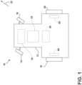
- FIGS. 1 and 2 illustrate differing views of one embodiment of a work vehicle 10 in accordance with the present subject matter. More specifically, FIGS. 1 and 2 illustrate top and side views of the work vehicle 10, respectively.
- the work vehicle 10 is configured as an agricultural tractor.
- the work vehicle 10 is configured as any other suitable agricultural or other type of work vehicle, such as an agricultural harvester, an agricultural sprayer, a construction vehicle, and/or the like.
- the work vehicle 10 includes a frame or chassis 12 configured to support or couple to a plurality of components.
- the work vehicle 10 includes one or more traction devices coupled to the frame 12.
- the work vehicle 10 includes a pair of steerable front wheels 14, 16, and a pair of driven rear wheels 18, 20 coupled to the frame 12.
- the wheels 14, 16 are, in turn, configured to support the work vehicle 10 relative to the ground and move the vehicle 10 in a direction of travel (e.g., as indicated by arrow 22) across a field.
- the work vehicle 10 includes an engine 24 and a transmission 26 mounted on the frame 12.
- the transmission 26 is operably coupled to the engine 24 and provides variably adjusted gear ratios for transferring engine power to the driven wheels 18, 20.
- an operator's cab 28 ( FIG.2 ) is supported by a portion of the frame 12 and may house various input devices, such as a brake pedal 30 ( FIG. 2 ) and a steering wheel 32 ( FIG. 2 ), for permitting an operator to control the operation of one or more components of the work vehicle 10.
- the work vehicle 10 may include any other suitable component(s) coupled to or supported on the frame 12.
- the front wheels 14, 16 may be driven in addition to, or in lieu of, the one or more rear wheels 18, 20.
- the work vehicle 10 includes one or more brake assemblies 60.
- the brake assembly(ies) 60 is configured to reduce the ground speed of or otherwise slow the movement of the work vehicle 10.
- the work vehicle 10 includes a braking assembly 60 provided in association with each of the driven wheels 18, 20.
- the braking assemblies 60 when activated, reduce the wheel speed of or otherwise slow the rotation of the wheels 18, 20.
- braking assemblies 60 may be provided in operative association with the front wheels 14, 16 in addition to or in lieu of the rear wheels 18, 20.
- the brake assembly(ies) 60 is configured to be activated during both service braking operations and auxiliary braking operations of the work vehicle 10.
- a service braking operation occurs when the braking assembly(ies) 60 is engaged to reduce the ground speed of the work vehicle 10, such as when the work vehicle 10 needs to be slowed to make a turn or avoid an obstacle.
- the brake pedal 30 may be used by the operator of the work vehicle 10 to initiate service braking operations. Alternatively, service braking operations may be initiated automatically.
- auxiliary braking operations correspond to engagement of the braking assemblies 60 occurring at times other than during service braking operations.
- engagement of the braking assemblies 60 to prevent movement of the work vehicle 10 when parked on a hill or other inclined surface constitutes an auxiliary braking operation.
- engagement of the braking assemblies 60 to reduce the ground speed of the work vehicle 10 to make a turn or avoid an obstacle in lieu of service braking operations constitutes an auxiliary braking operation.
- engagement of the braking assemblies 60 to reduce the ground speed of the work vehicle 10 when service braking operations are unavailable constitutes an auxiliary braking operation.
- the braking assemblies 60 correspond to any suitable device(s) for reducing the wheel speeds of the wheels 18, 20, such as by converting energy associated with the movement of such wheels 18, 20 into heat.
- the braking assemblies 60 correspond to a suitable fluid-driven cylinder(s) (not shown), such as a hydraulic cylinder(s), configured to push stationary frictional elements (not shown), such as brake shoes or brake calipers, against rotating elements (not shown), such as brake drums or brake discs.
- the braking assemblies 60 correspond to any other suitable hydraulic, pneumatic, mechanical, and/or electrical components configured to convert the rotation of the rotating elements into heat.
- FIG. 3 illustrates a perspective view of one embodiment of an auxiliary braking system 56 of a work vehicle 10.
- the auxiliary braking system 56 is configured to activate the braking assembly(ies) 60 during auxiliary braking operations.
- the auxiliary braking system 56 includes an auxiliary braking actuator 70 and a cable assembly 80.
- the cable assembly 80 is coupled between the auxiliary braking actuator 70 and a brake valve 66 associated with the braking assembly(ies) 60.
- the cable assembly 80 may include a clevis 64 that is coupled to an actuation arm 65 of the brake valve 66.
- the cable assembly 80 is configured to transmit movement of the auxiliary braking actuator 70 to the brake valve 66. Such movement actuates the brake valve 66 (e.g., by pivoting the actuation arm 65 of the brake valve 66), which, in turn, supplies brake fluid to the braking assembly(ies) 60 such that the auxiliary braking operation is performed.
- FIGS. 4 and 5 illustrate differing view of the auxiliary braking assembly 56 in accordance with the present subject matter. More specifically, FIG. 4 illustrates a partial, exploded perspective view of the auxiliary braking system 56. FIG. 5 illustrates a cross-sectional view of the auxiliary braking system 56 shown in FIG. 4 .
- the auxiliary braking system 56 includes the auxiliary braking actuator 70, which is configured to actuate the brake valve 66 associated with the braking assembly(ies) 60.
- the auxiliary braking actuator 70 includes a rod 74 having a first end 75 and second end 77 opposed to the first end 75.
- the first end 75 of the rod 74 extends outward from the auxiliary braking actuator 70 and defines a chamber 76 therein. Moreover, the first end 75 of the rod 74 is coupled to the cable assembly 80. In this respect, when activated, the rod 74 moves relative to the auxiliary braking actuator 70 such that the cable assembly 80 transmits this movement to the brake valve 66.
- the auxiliary braking actuator 70 is configured as a pneumatically actuated spring-loaded cylinder 72.
- a pneumatic force is applied to the spring-loaded cylinder 72.
- the rod 74 extends or retracts relative to the spring-loaded cylinder 72, thereby moving the cable assembly 80 in a manner that pivots the actuation arm 65 ( FIG. 3 ) of the brake valve 66 ( FIG. 3 ).
- the auxiliary braking actuator 70 corresponds to any other suitable hydraulic, pneumatic, mechanical, and/or electrical components configured to apply a force to the cable assembly 80.
- the auxiliary braking actuator 70 is automatically controlled without human intervention by a computing system (e.g., one or more controllers (not shown)).
- the computing system may receive an input or other data indicating that an auxiliary braking operation should be performed (e.g., sensor data indicating that the work vehicle 10 is parked on a hill). Thereafter, the computing system may transmit control signals to the auxiliary braking actuator 70 or an associated valve(s) (not shown). Such control signals, in turn, instruct the auxiliary braking actuator 70 or the associated valve(s) to move the rod in a manner that actuates the brake valve 66.
- the auxiliary braking system 56 includes the cable assembly 80.
- the cable assembly 80 includes a first end 82 and a second end 84 opposed to the first end 82. More specifically, the first end 82 includes a first enlarged head 83 that is slidably positioned within the chamber 76.
- the first enlarged head 83 of the cable assembly 80 is slideably positioned within the chamber 76 ( FIG. 5 ) of the auxiliary braking actuator 70 such that when a service braking actuator (not shown) activates the brake assembly 60, the first enlarged head 83 is configured to slide within the chamber 76 ( FIG. 5 ) of the auxiliary braking actuator 70.
- the second end 84 of the cable assembly 80 is coupled to the clevis 64 of the brake assembly 60 and the first end 82 of the cable assembly 80 including a first enlarged head 83.
- the second end 84 of the cable assembly 80 includes a second enlarged head 88 coupled to the clevis 64.
- the second end 84 of the cable assembly 80 may be coupled to the brake valve 66 in any other suitable manner.
- the cable assembly 80 is configured as a Bowden cable 110.
- the cable assembly 80 includes a cable 85 positioned within a sheath 112.
- the cable 85 includes a first end 86 and an opposed second end 87.
- the first enlarged head 83 encloses the first end 86 of the cable 85.
- the second enlarged head 88 encloses the second end 87 of the cable 85.
- the cable assembly 80 may be configured in any other suitable manner that allows for the cable assembly 80 to transmit the movement of the auxiliary braking actuator 70 to the brake valve 66.
- the auxiliary braking system 56 includes a fastener assembly 90.
- the fastener assembly 90 is configured to couple to the rod 74 to retain the first enlarged head 83 within the chamber 76 of the auxiliary braking actuator 70.
- the fastener assembly 90 includes a sleeve 91 positioned around a portion of the cable assembly 80.
- the sleeve 91 includes a first end 92 and a second end 93.
- the first end 92 of the sleeve 91 positioned within the chamber 76 to retain the first enlarged head 83 within the chamber 76.
- the sleeve 91 may have an outer surface 94 defining threading 95.
- an inner surface 78 of the rod 74 defines threading 79.
- the outer surface 94 of the sleeve 91 is configured to threadingly engage with an inner surface 78 of the rod 74.
- the fastener assembly 90 may include a nut 96 that threadingly engages the outer surface 94 of the sleeve 91.
- the fastener assembly 90 couples the rod 74 and the cable assembly 80 together.
- the cable assembly 80 is configured to transmit the force applied by the rod 74 to the brake valve 66 when an auxiliary braking operation is initiated.
- the auxiliary braking system 56 includes a seal member 101 coupled between the second end 93 of the sleeve 91 and the cable assembly 80 and configured to seal the chamber 76.
- the seal member 101 is used to prevent dirt and other foreign particles from entering the auxiliary braking actuator 70.
- the second end 93 of the sleeve 91 defines an enlarged portion 100 containing the seal member 101.
- the seal member 101 is configured as O-ring 102.
- the enlarged portion 100 is a hexagonal head 103.
- FIG. 6 illustrates an enlarged cross-sectional view of the FIG. 4 embodiment the auxiliary braking system 56.
- the first enlarged head 83 is positioned within the chamber 76 defined in the rod 74.
- the first enlarged end 83 and the first end 86 of the cable 85 are configured to slide, as indicated by arrow 200, within the chamber 76 of the rod 74 during service braking operations. More specifically, during service braking operations, the brake valve 66 is activated such that the cable 85 of the cable assembly 80 moves relative to the rod 74.
- the chamber 76 provides clearance for the cable 85 and the first enlarged head 83 coupled thereto to move relative to the rod 74.
- the positioning of the first enlarged head 83 within the chamber 74 allow for the auxiliary braking actuator 70 to be unaffected by the actuation of the brake valve 66 or other components of the braking assembly 60 during service braking operations.
- the sleeve 91 of the fastener assembly 90 is configured to confine the movement of the first enlarged head 83 and the first end 86 of the cable 85 within the chamber 76 of the rod 74 of the spring-loaded cylinder 72 as seen in the illustrated embodiment.
- a force activates the brake assembly 60 ( FIG. 3 ) such that the brake assembly 60 applies a force to the cable assembly 80.
- the force applied to the cable assembly 80 moves the first enlarged head 83 and the first end 86 of the cable 85 within the chamber 76 toward the first end 75 of the rod 74.
Landscapes
- Engineering & Computer Science (AREA)
- Transportation (AREA)
- Mechanical Engineering (AREA)
- Physics & Mathematics (AREA)
- Fluid Mechanics (AREA)
- Transmission Of Braking Force In Braking Systems (AREA)
- Braking Arrangements (AREA)
Abstract
In one aspect, an auxiliary braking system (56) for a work vehicle (10) including a traction device may include a brake assembly (60) being configured for slow movement of the traction device. The system may also include an auxiliary braking actuator (70) configured to selectively activate the brake assembly (60) during auxiliary braking operations. Furthermore, the system may include a cable (85) coupled to the brake assembly (60) and one end of the cable assembly (80) including an enlarged head (83) slidably positioned within a chamber (76) of an auxiliary braking actuator (70), wherein, when a service braking actuator activates the brake assembly (60), the enlarged head (83) is configured to slide within the chamber (76). Finally, the system may include a fastener assembly (90) to retain the enlarged head (83) within the chamber (76).
Description
- The present disclosure generally relates to work vehicles and, more particularly, to an auxiliary braking system for a work vehicle.
- It is well known that, to slow or stop the movement of a tractor or other work vehicle, a braking force must be applied to the work vehicle. Traditionally, operators use various manual input devices to apply a braking force to slow or stop the movement of a work vehicle. For example, the operator may use a foot pedal to apply a service braking force to the work vehicle and a hand lever for applying an auxiliary braking force to the work. Recently, autonomous work vehicles have been developed. Such autonomous work vehicles can be controlled without the presence of an operator within the cab. Thus, the operator is not available to actuate the manual input devices for slowing the work vehicle.
- Accordingly, an improved auxiliary braking system for a work vehicle would be welcomed in the technology.
- Aspects and advantages of the technology will be set forth in part in the following description, or may be obvious from the description, or may be learned through practice of the technology.
- In one aspect, the present subject matter is directed to an auxiliary braking system for a work vehicle including a brake assembly. Furthermore, the auxiliary braking system includes an auxiliary braking actuator configured to selectively activate the brake assembly during auxiliary braking operations. In this respect, the auxiliary braking actuator includes a rod having a first end and second end opposed to the first end. In addition, the first end of the rod defines a chamber. Furthermore, the auxiliary braking system includes a cable assembly. In this respect, the cable assembly includes a first end and a second end opposed to the first end. In addition, the second end of the cable assembly is coupled to the brake assembly. Additionally, the first end of the cable assembly includes a first enlarged head slideably positioned within the chamber. Furthermore, the auxiliary braking system includes a fastener assembly coupled to the rod to retain the first enlarged head within the chamber. Furthermore, when a service braking actuator activates the brake assembly of the auxiliary braking system, the first enlarged head is configured to slide within the chamber.
- In another aspect, the present subject matter is directed to a work vehicle including a traction device. Furthermore, the work vehicle includes a brake assembly. In this respect, the brake assembly is configured to slow movement of the traction device. Furthermore, the work vehicle includes a service braking actuator. In this respect, the service braking actuator is configured to activate the brake assembly during service braking operations.
- Furthermore, the work vehicle includes an auxiliary braking actuator. In this respect, the auxiliary braking actuator is configured to selectively activate the brake assembly during auxiliary braking operations. In addition, the auxiliary braking actuator includes a rod having a first end and a second end opposed to the first end. In addition, the first end of the rod defines a chamber. Furthermore, the work vehicle includes a cable assembly. In this respect, the cable assembly includes a first end and a second end opposed to the first end. In addition, the second end of the cable assembly is coupled to the brake assembly. Additionally, the first end of the cable assembly includes a first enlarged head slideably positioned within the chamber. Additionally, the cable assembly includes a fastener assembly coupled to the rod to retain the first enlarged head within the chamber. Furthermore, when a service braking actuator activates the brake assembly of the auxiliary braking system, the first enlarged head is configured to slide within the chamber. These and other features, aspects and advantages of the present technology will become better understood with reference to the following description and appended claims. The accompanying drawings, which are incorporated therein and constitute a part of this specification, illustrate embodiments of the technology and, together with the description, serve to explain the principles of the technology.
- A full and enabling disclosure of the present technology, including the best mode thereof, directed to one of ordinary skill in the art, is set forth in the specification, which makes reference to the appended figures, in which:
-
FIG. 1 illustrates a top view of one embodiment of a work vehicle in accordance with aspects of the present subject matter; -
FIG. 2 illustrates a side view of the work vehicle shown inFIG. 1 , particularly illustrating various components of the work vehicle in accordance with aspects of the present subject matter; -
FIG. 3 illustrates a perspective view of one embodiment of an auxiliary braking system for a work vehicle in accordance with aspects of the present subject matter; -
FIG. 4 illustrates a partial, exploded perspective view of one embodiment of an auxiliary braking system for a work vehicle in accordance with aspects of the present subject matter; -
FIG. 5 illustrates a cross-sectional view of the auxiliary braking system shown inFIG. 4 ; -
FIG. 6 illustrates an enlarged, partial cross-sectional view of the auxiliary braking system shown inFIGS. 4 and5 , particularly illustrating a chamber of an auxiliary braking actuator of the auxiliary braking system; and -
FIG. 7 illustrates another enlarged, partial cross-sectional view of the auxiliary braking actuator shown inFIGS. 4-6 , particularly illustrating threading of a rod of the auxiliary braking actuator. - Repeat use of reference characters in the present specification and drawings is intended to represent the same or analogous features or elements of the present technology.
- Reference now will be made in detail to embodiments of the invention, one or more examples of which are illustrated in the drawings. Each example is provided by way of explanation of the invention, not limitation of the invention. In fact, it will be apparent to those skilled in the art that various modifications and variations can be made in the present invention. For instance, features illustrated or described as part of one embodiment can be used with another embodiment to yield still a further embodiment. Thus, it is intended that the present invention covers such modifications and variations as come within the scope of the appended claims and their equivalents.
- In general, the present subject matter is directed to an auxiliary braking system for a work vehicle. More specifically, the auxiliary braking system includes an auxiliary braking actuator configured to selectively activate a brake assembly of the work vehicle during auxiliary braking operations. The brake assembly is, in turn, configured to slow movement of a traction device(s) of the work vehicle. In several embodiments, the auxiliary braking actuator is automatically controlled (e.g., by a suitable computing system). For example, in one embodiment, the auxiliary braking actuator is a spring-loaded cylinder configured to activate the brake assembly during auxiliary braking operations, such as when the work vehicle is stopped on an inclined surface. In this respect, the auxiliary braking actuator includes a rod having a first and second end, with the first end of the rod extending outward from the actuator and defining a chamber.
- Additionally, in several embodiments, the auxiliary braking system includes a cable assembly including a first and second end. The first end of the cable assembly includes a first enlarged head that is slideably positioned within the chamber of the auxiliary braking actuator. Additionally, in several embodiments, the second end of the cable assembly is coupled to the brake assembly. In this respect, during service braking operations (e.g., when the reducing the ground speed of the work vehicle during operation), a separate service braking actuator activates the brake assembly. Such activation of the brake assembly, in turn, causes movement of the cable assembly relative to the auxiliary braking actuator. Thus, the first enlarged end of the cable assembly can slide within the chamber to accommodate movement the such movement of the cable assembly during service braking operations.
- Referring now to the drawings,
FIGS. 1 and2 illustrate differing views of one embodiment of awork vehicle 10 in accordance with the present subject matter. More specifically,FIGS. 1 and2 illustrate top and side views of thework vehicle 10, respectively. - As shown, in the illustrated embodiment, the
work vehicle 10 is configured as an agricultural tractor. However, in other embodiments, thework vehicle 10 is configured as any other suitable agricultural or other type of work vehicle, such as an agricultural harvester, an agricultural sprayer, a construction vehicle, and/or the like. - As shown in
FIGS. 1 and2 , thework vehicle 10 includes a frame orchassis 12 configured to support or couple to a plurality of components. Specifically, in several embodiments, thework vehicle 10 includes one or more traction devices coupled to theframe 12. For example, in the illustrated embodiment, thework vehicle 10 includes a pair of steerablefront wheels rear wheels frame 12. Thewheels work vehicle 10 relative to the ground and move thevehicle 10 in a direction of travel (e.g., as indicated by arrow 22) across a field. In this regard, thework vehicle 10 includes anengine 24 and atransmission 26 mounted on theframe 12. Thetransmission 26 is operably coupled to theengine 24 and provides variably adjusted gear ratios for transferring engine power to the drivenwheels FIG.2 ) is supported by a portion of theframe 12 and may house various input devices, such as a brake pedal 30 (FIG. 2 ) and a steering wheel 32 (FIG. 2 ), for permitting an operator to control the operation of one or more components of thework vehicle 10. However, in alternative embodiments, thework vehicle 10 may include any other suitable component(s) coupled to or supported on theframe 12. For example, in one alternative embodiment, thefront wheels rear wheels - Furthermore, in several embodiments, the
work vehicle 10 includes one ormore brake assemblies 60. In general, the brake assembly(ies) 60 is configured to reduce the ground speed of or otherwise slow the movement of thework vehicle 10. For example, in the illustrated embodiment, thework vehicle 10 includes abraking assembly 60 provided in association with each of the drivenwheels braking assemblies 60 reduce the wheel speed of or otherwise slow the rotation of thewheels braking assemblies 60 may be provided in operative association with thefront wheels rear wheels - In general, the brake assembly(ies) 60 is configured to be activated during both service braking operations and auxiliary braking operations of the
work vehicle 10. A service braking operation occurs when the braking assembly(ies) 60 is engaged to reduce the ground speed of thework vehicle 10, such as when thework vehicle 10 needs to be slowed to make a turn or avoid an obstacle. In one embodiment, thebrake pedal 30 may be used by the operator of thework vehicle 10 to initiate service braking operations. Alternatively, service braking operations may be initiated automatically. - Conversely, auxiliary braking operations correspond to engagement of the
braking assemblies 60 occurring at times other than during service braking operations. For example, engagement of thebraking assemblies 60 to prevent movement of thework vehicle 10 when parked on a hill or other inclined surface constitutes an auxiliary braking operation. As another example, engagement of thebraking assemblies 60 to reduce the ground speed of thework vehicle 10 to make a turn or avoid an obstacle in lieu of service braking operations constitutes an auxiliary braking operation. As still a further example, engagement of thebraking assemblies 60 to reduce the ground speed of thework vehicle 10 when service braking operations are unavailable constitutes an auxiliary braking operation. - Additionally, it should be appreciated that the
braking assemblies 60 correspond to any suitable device(s) for reducing the wheel speeds of thewheels such wheels braking assemblies 60 correspond to a suitable fluid-driven cylinder(s) (not shown), such as a hydraulic cylinder(s), configured to push stationary frictional elements (not shown), such as brake shoes or brake calipers, against rotating elements (not shown), such as brake drums or brake discs. However, it should be appreciated that thebraking assemblies 60 correspond to any other suitable hydraulic, pneumatic, mechanical, and/or electrical components configured to convert the rotation of the rotating elements into heat. -
FIG. 3 illustrates a perspective view of one embodiment of anauxiliary braking system 56 of awork vehicle 10. In general, theauxiliary braking system 56 is configured to activate the braking assembly(ies) 60 during auxiliary braking operations. Specifically, in several embodiments, theauxiliary braking system 56 includes anauxiliary braking actuator 70 and acable assembly 80. Thecable assembly 80 is coupled between theauxiliary braking actuator 70 and abrake valve 66 associated with the braking assembly(ies) 60. For example, in one embodiment, thecable assembly 80 may include aclevis 64 that is coupled to anactuation arm 65 of thebrake valve 66. In this respect, thecable assembly 80 is configured to transmit movement of theauxiliary braking actuator 70 to thebrake valve 66. Such movement actuates the brake valve 66 (e.g., by pivoting theactuation arm 65 of the brake valve 66), which, in turn, supplies brake fluid to the braking assembly(ies) 60 such that the auxiliary braking operation is performed. -
FIGS. 4 and5 illustrate differing view of theauxiliary braking assembly 56 in accordance with the present subject matter. More specifically,FIG. 4 illustrates a partial, exploded perspective view of theauxiliary braking system 56.FIG. 5 illustrates a cross-sectional view of theauxiliary braking system 56 shown inFIG. 4 . As mentioned above, theauxiliary braking system 56 includes theauxiliary braking actuator 70, which is configured to actuate thebrake valve 66 associated with the braking assembly(ies) 60. Specifically, in several embodiments, theauxiliary braking actuator 70 includes arod 74 having afirst end 75 andsecond end 77 opposed to thefirst end 75. As shown, thefirst end 75 of therod 74 extends outward from theauxiliary braking actuator 70 and defines achamber 76 therein. Moreover, thefirst end 75 of therod 74 is coupled to thecable assembly 80. In this respect, when activated, therod 74 moves relative to theauxiliary braking actuator 70 such that thecable assembly 80 transmits this movement to thebrake valve 66. - In the illustrated embodiment, the
auxiliary braking actuator 70 is configured as a pneumatically actuated spring-loadedcylinder 72. In such embodiments, to initiate auxiliary braking operations, a pneumatic force is applied to the spring-loadedcylinder 72. When the pneumatic force is applied to the spring-loadedcylinder 72, therod 74 extends or retracts relative to the spring-loadedcylinder 72, thereby moving thecable assembly 80 in a manner that pivots the actuation arm 65 (FIG. 3 ) of the brake valve 66 (FIG. 3 ). However, it should be appreciated that theauxiliary braking actuator 70 corresponds to any other suitable hydraulic, pneumatic, mechanical, and/or electrical components configured to apply a force to thecable assembly 80. - In some embodiments, the
auxiliary braking actuator 70 is automatically controlled without human intervention by a computing system (e.g., one or more controllers (not shown)). In such embodiments, the computing system may receive an input or other data indicating that an auxiliary braking operation should be performed (e.g., sensor data indicating that thework vehicle 10 is parked on a hill). Thereafter, the computing system may transmit control signals to theauxiliary braking actuator 70 or an associated valve(s) (not shown). Such control signals, in turn, instruct theauxiliary braking actuator 70 or the associated valve(s) to move the rod in a manner that actuates thebrake valve 66. - Furthermore, as mentioned above, the
auxiliary braking system 56 includes thecable assembly 80. As shown, thecable assembly 80 includes afirst end 82 and asecond end 84 opposed to thefirst end 82. More specifically, thefirst end 82 includes a firstenlarged head 83 that is slidably positioned within thechamber 76. As will be described below, the firstenlarged head 83 of thecable assembly 80 is slideably positioned within the chamber 76 (FIG. 5 ) of theauxiliary braking actuator 70 such that when a service braking actuator (not shown) activates thebrake assembly 60, the firstenlarged head 83 is configured to slide within the chamber 76 (FIG. 5 ) of theauxiliary braking actuator 70. Furthermore, thesecond end 84 of thecable assembly 80 is coupled to theclevis 64 of thebrake assembly 60 and thefirst end 82 of thecable assembly 80 including a firstenlarged head 83. For example, in the illustrated embodiment, thesecond end 84 of thecable assembly 80 includes a secondenlarged head 88 coupled to theclevis 64. However, in alternative embodiments, thesecond end 84 of thecable assembly 80 may be coupled to thebrake valve 66 in any other suitable manner. - Additionally, in the illustrated embodiment, the
cable assembly 80 is configured as aBowden cable 110. In such an embodiment, thecable assembly 80 includes acable 85 positioned within a sheath 112. As such, thecable 85 includes afirst end 86 and an opposedsecond end 87. In this respect, the firstenlarged head 83 encloses thefirst end 86 of thecable 85. Similarly, the secondenlarged head 88 encloses thesecond end 87 of thecable 85. However, in alternative embodiments, thecable assembly 80 may be configured in any other suitable manner that allows for thecable assembly 80 to transmit the movement of theauxiliary braking actuator 70 to thebrake valve 66. - Moreover, in some embodiments, the
auxiliary braking system 56 includes afastener assembly 90. In general, thefastener assembly 90 is configured to couple to therod 74 to retain the firstenlarged head 83 within thechamber 76 of theauxiliary braking actuator 70. For example, in the illustrated embodiment, thefastener assembly 90 includes asleeve 91 positioned around a portion of thecable assembly 80. Thesleeve 91 includes afirst end 92 and asecond end 93. Thefirst end 92 of thesleeve 91 positioned within thechamber 76 to retain the firstenlarged head 83 within thechamber 76. For example, in one embodiment, thesleeve 91 may have anouter surface 94 definingthreading 95. Similarly, as shown inFIG. 7 , aninner surface 78 of therod 74 defines threading 79. As such, theouter surface 94 of thesleeve 91 is configured to threadingly engage with aninner surface 78 of therod 74. Additionally, thefastener assembly 90 may include anut 96 that threadingly engages theouter surface 94 of thesleeve 91. Thus, by varying the position of thenut 96 along theouter surface 94 of thesleeve 91, the size of thechamber 76 can be adjusted. - Referring again to
FIGS. 4 and5 , as mentioned above, thefastener assembly 90 couples therod 74 and thecable assembly 80 together. In this respect, thecable assembly 80 is configured to transmit the force applied by therod 74 to thebrake valve 66 when an auxiliary braking operation is initiated. - Further in the illustrated embodiment, the
auxiliary braking system 56 includes aseal member 101 coupled between thesecond end 93 of thesleeve 91 and thecable assembly 80 and configured to seal thechamber 76. Theseal member 101 is used to prevent dirt and other foreign particles from entering theauxiliary braking actuator 70. In one embodiment, thesecond end 93 of thesleeve 91 defines anenlarged portion 100 containing theseal member 101. In one further embodiment, theseal member 101 is configured as O-ring 102. In still one further embodiment, theenlarged portion 100 is ahexagonal head 103. -
FIG. 6 illustrates an enlarged cross-sectional view of theFIG. 4 embodiment theauxiliary braking system 56. As mentioned above, the firstenlarged head 83 is positioned within thechamber 76 defined in therod 74. Moreover, the firstenlarged end 83 and thefirst end 86 of thecable 85 are configured to slide, as indicated byarrow 200, within thechamber 76 of therod 74 during service braking operations. More specifically, during service braking operations, thebrake valve 66 is activated such that thecable 85 of thecable assembly 80 moves relative to therod 74. In this respect, thechamber 76 provides clearance for thecable 85 and the firstenlarged head 83 coupled thereto to move relative to therod 74. Thus, the positioning of the firstenlarged head 83 within thechamber 74 allow for theauxiliary braking actuator 70 to be unaffected by the actuation of thebrake valve 66 or other components of thebraking assembly 60 during service braking operations. - Additionally, the
sleeve 91 of thefastener assembly 90 is configured to confine the movement of the firstenlarged head 83 and thefirst end 86 of thecable 85 within thechamber 76 of therod 74 of the spring-loadedcylinder 72 as seen in the illustrated embodiment. During auxiliary braking operations, a force activates the brake assembly 60 (FIG. 3 ) such that thebrake assembly 60 applies a force to thecable assembly 80. The force applied to thecable assembly 80 moves the firstenlarged head 83 and thefirst end 86 of thecable 85 within thechamber 76 toward thefirst end 75 of therod 74. - This written description uses examples to disclose the technology, including the best mode, and also to enable any person skilled in the art to practice the technology, including making and using any devices or systems and performing any incorporated methods. The patentable scope of the technology is defined by the claims, and may include other examples that occur to those skilled in the art. Such other examples are intended to be within the scope of the claims if they include structural elements that do not differ from the literal language of the claims, or if they include equivalent structural elements with insubstantial differences from the literal language of the claims.
Claims (12)
- An auxiliary braking system (56) for a work vehicle (10), the auxiliary braking system (56) comprising:a brake assembly (60);an auxiliary braking actuator (70) configured to selectively activate the brake assembly (60) during auxiliary braking operations, the auxiliary braking actuator (70) including a rod (74) having a first end (75) and second end (77) opposed to the first end (75), the first end (75) of the rod (74) defining a chamber (76);a cable assembly (80) including a first end (82) and a second end (84) opposed to the first end, the second end of the cable assembly (80) coupled to the brake assembly (60), the first end (82) of the cable assembly (80) including a first enlarged head (83) slidably positioned within the chamber (76); anda fastener assembly (90) coupled to the rod (74) to retain the first enlarged head (83) within the chamber (76),wherein, when the brake assembly (60) is activated during service braking operations, the first enlarged head (83) is configured to slide within the chamber (76).
- The auxiliary braking system (56) of claim 1, wherein the fastener assembly (60) comprises a sleeve (91) positioned around a portion of the cable assembly (80), the sleeve (91) including a first end (92) and a second end (93) opposed to the first end (92), the first end (92) of the sleeve (91) being positioned within the chamber (76) to retain the first enlarged head (83) within the chamber (76).
- The auxiliary braking system (56) of claim 2, wherein an outer surface (94) of the first end (92) of the sleeve (91) threadingly engages an inner surface (78) of the rod (74).
- The auxiliary braking system (56) of claim 3, wherein the fastener assembly (60) further comprises a nut (96) that threadingly engages an outer surface (94) of the sleeve (91).
- The auxiliary braking system (56) of claim 4, the second end (84) of the cable assembly (80) including a second end (87) of the cable (85) and a second enlarged head (88), wherein the second enlarged head (88) encloses the second end (87) of the cable (85).
- The auxiliary braking system (56) of claim 5, the first end (82) of the cable assembly (80) further including a first end (86) of the cable (85), wherein the first enlarged head (83) encloses the first end (86) of the cable (85).
- The auxiliary braking system (56) of any preceding claim, further comprising:
a seal member (101) coupled between the second end (93) of the sleeve (91) and the cable assembly (80), the seal member (101) configured to seal the chamber (76). - The auxiliary braking system (56) of claim 7, the second end (93) of the sleeve (91) defining an enlarged portion (100) containing the seal member (101).
- The auxiliary braking system (56) of any of claims 7 or 8, wherein the seal member (101) comprises an o-ring (102).
- The auxiliary braking system (56) of any of claims 7 to 9, wherein the cable assembly (80) comprises a Bowden cable (110).
- The auxiliary braking system (56) of any preceding claim, wherein the brake assembly (60) comprises a clevis (64) coupled to the second end (84) of the cable assembly (80).
- A work vehicle (10), comprising:a traction device;a service braking actuator configured to activate the brake assembly (60) during service braking operations; and,the auxiliary braking system (56) for the work vehicle (10) of any preceding claim.
Applications Claiming Priority (1)
| Application Number | Priority Date | Filing Date | Title |
|---|---|---|---|
| US18/085,865 US20240208476A1 (en) | 2022-12-21 | 2022-12-21 | Auxiliary braking system for a work vehicle |
Publications (1)
| Publication Number | Publication Date |
|---|---|
| EP4389545A1 true EP4389545A1 (en) | 2024-06-26 |
Family
ID=89224773
Family Applications (1)
| Application Number | Title | Priority Date | Filing Date |
|---|---|---|---|
| EP23218742.7A Pending EP4389545A1 (en) | 2022-12-21 | 2023-12-20 | Auxiliary braking system for a work vehicle |
Country Status (3)
| Country | Link |
|---|---|
| US (1) | US20240208476A1 (en) |
| EP (1) | EP4389545A1 (en) |
| CN (1) | CN118220071A (en) |
Citations (3)
| Publication number | Priority date | Publication date | Assignee | Title |
|---|---|---|---|---|
| US5119912A (en) * | 1991-08-02 | 1992-06-09 | General Motors Corporation | Automatic/mechanical apply park brake distributor |
| US5180038A (en) * | 1992-01-24 | 1993-01-19 | Orscheln Co. | Electronically controlled parking brake system |
| EP2457787A1 (en) * | 2004-06-30 | 2012-05-30 | HI-LEX Corporation, Inc. | An electric cable drive device |
-
2022
- 2022-12-21 US US18/085,865 patent/US20240208476A1/en active Pending
-
2023
- 2023-12-20 EP EP23218742.7A patent/EP4389545A1/en active Pending
- 2023-12-21 CN CN202311774362.1A patent/CN118220071A/en active Pending
Patent Citations (3)
| Publication number | Priority date | Publication date | Assignee | Title |
|---|---|---|---|---|
| US5119912A (en) * | 1991-08-02 | 1992-06-09 | General Motors Corporation | Automatic/mechanical apply park brake distributor |
| US5180038A (en) * | 1992-01-24 | 1993-01-19 | Orscheln Co. | Electronically controlled parking brake system |
| EP2457787A1 (en) * | 2004-06-30 | 2012-05-30 | HI-LEX Corporation, Inc. | An electric cable drive device |
Also Published As
| Publication number | Publication date |
|---|---|
| US20240208476A1 (en) | 2024-06-27 |
| CN118220071A (en) | 2024-06-21 |
Similar Documents
| Publication | Publication Date | Title |
|---|---|---|
| DE3541354A1 (en) | MOUNTAIN STARTING AID FOR A VEHICLE | |
| AU2021202105A1 (en) | Park brake and traction drive bypass interlock | |
| US3729074A (en) | Parking brake control with transmission interlock | |
| EP3868620B1 (en) | Vehicle propelled with a hydrostatic drive unit and braking method | |
| EP3351458A1 (en) | Brake assisted turning | |
| US10894536B2 (en) | Service brake actuation using a linear actuator | |
| US20240208476A1 (en) | Auxiliary braking system for a work vehicle | |
| RU192314U1 (en) | LADDER-CONNECTED DEVICE WITH LOCKING AND TRAFFIC CONTROL SYSTEM | |
| JPH07257356A (en) | Brake device for vehicle | |
| US7077221B2 (en) | Hydrostatic pump destroke braking mechanism | |
| US5119912A (en) | Automatic/mechanical apply park brake distributor | |
| BR102023026653A2 (en) | AUXILIARY BRAKING SYSTEM FOR A WORK VEHICLE | |
| CN110143193A (en) | An emergency parking system with electronic handbrake | |
| JP6157384B2 (en) | Brake device for vehicle | |
| US4266832A (en) | Vehicle wheel anti-slip device | |
| US5186295A (en) | Tractor pedal arrangement with anti-declutching feature | |
| JP3618039B2 (en) | Work vehicle | |
| JPH0535032Y2 (en) | ||
| CA2221960C (en) | Hydraulic brake apparatus for braking a vehicle | |
| EP0849134A1 (en) | Engine-driven hydraulic servo system for braking and steering | |
| US2145373A (en) | Hydraulic servo-brake for motor vehicles | |
| EP1516791A3 (en) | A parking brake for a motor vehicle, in particular for a tractor. | |
| US6155652A (en) | Cam activated hydraulic braking system | |
| RU22645U1 (en) | DEVICE FOR REDUCING TOWING ONE OF THE DRIVING WHEELS | |
| JP2019196134A (en) | Work vehicle |
Legal Events
| Date | Code | Title | Description |
|---|---|---|---|
| PUAI | Public reference made under article 153(3) epc to a published international application that has entered the european phase |
Free format text: ORIGINAL CODE: 0009012 |
|
| STAA | Information on the status of an ep patent application or granted ep patent |
Free format text: STATUS: THE APPLICATION HAS BEEN PUBLISHED |
|
| AK | Designated contracting states |
Kind code of ref document: A1 Designated state(s): AL AT BE BG CH CY CZ DE DK EE ES FI FR GB GR HR HU IE IS IT LI LT LU LV MC ME MK MT NL NO PL PT RO RS SE SI SK SM TR |
|
| STAA | Information on the status of an ep patent application or granted ep patent |
Free format text: STATUS: REQUEST FOR EXAMINATION WAS MADE |
|
| 17P | Request for examination filed |
Effective date: 20250102 |