EP4389526A1 - Noise control method and noise control device - Google Patents
Noise control method and noise control device Download PDFInfo
- Publication number
- EP4389526A1 EP4389526A1 EP21953619.0A EP21953619A EP4389526A1 EP 4389526 A1 EP4389526 A1 EP 4389526A1 EP 21953619 A EP21953619 A EP 21953619A EP 4389526 A1 EP4389526 A1 EP 4389526A1
- Authority
- EP
- European Patent Office
- Prior art keywords
- engine
- noise
- controller
- reduction performance
- control method
- Prior art date
- Legal status (The legal status is an assumption and is not a legal conclusion. Google has not performed a legal analysis and makes no representation as to the accuracy of the status listed.)
- Withdrawn
Links
Images


Classifications
-
- G—PHYSICS
- G10—MUSICAL INSTRUMENTS; ACOUSTICS
- G10K—SOUND-PRODUCING DEVICES; METHODS OR DEVICES FOR PROTECTING AGAINST, OR FOR DAMPING, NOISE OR OTHER ACOUSTIC WAVES IN GENERAL; ACOUSTICS NOT OTHERWISE PROVIDED FOR
- G10K11/00—Methods or devices for transmitting, conducting or directing sound in general; Methods or devices for protecting against, or for damping, noise or other acoustic waves in general
- G10K11/16—Methods or devices for protecting against, or for damping, noise or other acoustic waves in general
- G10K11/175—Methods or devices for protecting against, or for damping, noise or other acoustic waves in general using interference effects; Masking sound
- G10K11/178—Methods or devices for protecting against, or for damping, noise or other acoustic waves in general using interference effects; Masking sound by electro-acoustically regenerating the original acoustic waves in anti-phase
- G10K11/1783—Methods or devices for protecting against, or for damping, noise or other acoustic waves in general using interference effects; Masking sound by electro-acoustically regenerating the original acoustic waves in anti-phase handling or detecting of non-standard events or conditions, e.g. changing operating modes under specific operating conditions
-
- B—PERFORMING OPERATIONS; TRANSPORTING
- B60—VEHICLES IN GENERAL
- B60R—VEHICLES, VEHICLE FITTINGS, OR VEHICLE PARTS, NOT OTHERWISE PROVIDED FOR
- B60R11/00—Arrangements for holding or mounting articles, not otherwise provided for
- B60R11/02—Arrangements for holding or mounting articles, not otherwise provided for for radio sets, television sets, telephones, or the like; Arrangement of controls thereof
-
- G—PHYSICS
- G10—MUSICAL INSTRUMENTS; ACOUSTICS
- G10K—SOUND-PRODUCING DEVICES; METHODS OR DEVICES FOR PROTECTING AGAINST, OR FOR DAMPING, NOISE OR OTHER ACOUSTIC WAVES IN GENERAL; ACOUSTICS NOT OTHERWISE PROVIDED FOR
- G10K11/00—Methods or devices for transmitting, conducting or directing sound in general; Methods or devices for protecting against, or for damping, noise or other acoustic waves in general
- G10K11/16—Methods or devices for protecting against, or for damping, noise or other acoustic waves in general
- G10K11/175—Methods or devices for protecting against, or for damping, noise or other acoustic waves in general using interference effects; Masking sound
-
- G—PHYSICS
- G10—MUSICAL INSTRUMENTS; ACOUSTICS
- G10K—SOUND-PRODUCING DEVICES; METHODS OR DEVICES FOR PROTECTING AGAINST, OR FOR DAMPING, NOISE OR OTHER ACOUSTIC WAVES IN GENERAL; ACOUSTICS NOT OTHERWISE PROVIDED FOR
- G10K11/00—Methods or devices for transmitting, conducting or directing sound in general; Methods or devices for protecting against, or for damping, noise or other acoustic waves in general
- G10K11/16—Methods or devices for protecting against, or for damping, noise or other acoustic waves in general
- G10K11/175—Methods or devices for protecting against, or for damping, noise or other acoustic waves in general using interference effects; Masking sound
- G10K11/178—Methods or devices for protecting against, or for damping, noise or other acoustic waves in general using interference effects; Masking sound by electro-acoustically regenerating the original acoustic waves in anti-phase
-
- G—PHYSICS
- G10—MUSICAL INSTRUMENTS; ACOUSTICS
- G10K—SOUND-PRODUCING DEVICES; METHODS OR DEVICES FOR PROTECTING AGAINST, OR FOR DAMPING, NOISE OR OTHER ACOUSTIC WAVES IN GENERAL; ACOUSTICS NOT OTHERWISE PROVIDED FOR
- G10K11/00—Methods or devices for transmitting, conducting or directing sound in general; Methods or devices for protecting against, or for damping, noise or other acoustic waves in general
- G10K11/16—Methods or devices for protecting against, or for damping, noise or other acoustic waves in general
- G10K11/175—Methods or devices for protecting against, or for damping, noise or other acoustic waves in general using interference effects; Masking sound
- G10K11/178—Methods or devices for protecting against, or for damping, noise or other acoustic waves in general using interference effects; Masking sound by electro-acoustically regenerating the original acoustic waves in anti-phase
- G10K11/1781—Methods or devices for protecting against, or for damping, noise or other acoustic waves in general using interference effects; Masking sound by electro-acoustically regenerating the original acoustic waves in anti-phase characterised by the analysis of input or output signals, e.g. frequency range, modes, transfer functions
- G10K11/17821—Methods or devices for protecting against, or for damping, noise or other acoustic waves in general using interference effects; Masking sound by electro-acoustically regenerating the original acoustic waves in anti-phase characterised by the analysis of input or output signals, e.g. frequency range, modes, transfer functions characterised by the analysis of the input signals only
-
- G—PHYSICS
- G10—MUSICAL INSTRUMENTS; ACOUSTICS
- G10K—SOUND-PRODUCING DEVICES; METHODS OR DEVICES FOR PROTECTING AGAINST, OR FOR DAMPING, NOISE OR OTHER ACOUSTIC WAVES IN GENERAL; ACOUSTICS NOT OTHERWISE PROVIDED FOR
- G10K11/00—Methods or devices for transmitting, conducting or directing sound in general; Methods or devices for protecting against, or for damping, noise or other acoustic waves in general
- G10K11/16—Methods or devices for protecting against, or for damping, noise or other acoustic waves in general
- G10K11/175—Methods or devices for protecting against, or for damping, noise or other acoustic waves in general using interference effects; Masking sound
- G10K11/178—Methods or devices for protecting against, or for damping, noise or other acoustic waves in general using interference effects; Masking sound by electro-acoustically regenerating the original acoustic waves in anti-phase
- G10K11/1781—Methods or devices for protecting against, or for damping, noise or other acoustic waves in general using interference effects; Masking sound by electro-acoustically regenerating the original acoustic waves in anti-phase characterised by the analysis of input or output signals, e.g. frequency range, modes, transfer functions
- G10K11/17821—Methods or devices for protecting against, or for damping, noise or other acoustic waves in general using interference effects; Masking sound by electro-acoustically regenerating the original acoustic waves in anti-phase characterised by the analysis of input or output signals, e.g. frequency range, modes, transfer functions characterised by the analysis of the input signals only
- G10K11/17823—Reference signals, e.g. ambient acoustic environment
-
- G—PHYSICS
- G10—MUSICAL INSTRUMENTS; ACOUSTICS
- G10K—SOUND-PRODUCING DEVICES; METHODS OR DEVICES FOR PROTECTING AGAINST, OR FOR DAMPING, NOISE OR OTHER ACOUSTIC WAVES IN GENERAL; ACOUSTICS NOT OTHERWISE PROVIDED FOR
- G10K11/00—Methods or devices for transmitting, conducting or directing sound in general; Methods or devices for protecting against, or for damping, noise or other acoustic waves in general
- G10K11/16—Methods or devices for protecting against, or for damping, noise or other acoustic waves in general
- G10K11/175—Methods or devices for protecting against, or for damping, noise or other acoustic waves in general using interference effects; Masking sound
- G10K11/178—Methods or devices for protecting against, or for damping, noise or other acoustic waves in general using interference effects; Masking sound by electro-acoustically regenerating the original acoustic waves in anti-phase
- G10K11/1787—General system configurations
- G10K11/17873—General system configurations using a reference signal without an error signal, e.g. pure feedforward
-
- G—PHYSICS
- G10—MUSICAL INSTRUMENTS; ACOUSTICS
- G10K—SOUND-PRODUCING DEVICES; METHODS OR DEVICES FOR PROTECTING AGAINST, OR FOR DAMPING, NOISE OR OTHER ACOUSTIC WAVES IN GENERAL; ACOUSTICS NOT OTHERWISE PROVIDED FOR
- G10K11/00—Methods or devices for transmitting, conducting or directing sound in general; Methods or devices for protecting against, or for damping, noise or other acoustic waves in general
- G10K11/16—Methods or devices for protecting against, or for damping, noise or other acoustic waves in general
- G10K11/175—Methods or devices for protecting against, or for damping, noise or other acoustic waves in general using interference effects; Masking sound
- G10K11/178—Methods or devices for protecting against, or for damping, noise or other acoustic waves in general using interference effects; Masking sound by electro-acoustically regenerating the original acoustic waves in anti-phase
- G10K11/1787—General system configurations
- G10K11/17879—General system configurations using both a reference signal and an error signal
- G10K11/17883—General system configurations using both a reference signal and an error signal the reference signal being derived from a machine operating condition, e.g. engine RPM or vehicle speed
-
- G—PHYSICS
- G10—MUSICAL INSTRUMENTS; ACOUSTICS
- G10K—SOUND-PRODUCING DEVICES; METHODS OR DEVICES FOR PROTECTING AGAINST, OR FOR DAMPING, NOISE OR OTHER ACOUSTIC WAVES IN GENERAL; ACOUSTICS NOT OTHERWISE PROVIDED FOR
- G10K2210/00—Details of active noise control [ANC] covered by G10K11/178 but not provided for in any of its subgroups
- G10K2210/10—Applications
- G10K2210/128—Vehicles
- G10K2210/1282—Automobiles
Definitions
- the present invention relates to a noise control method and a noise control device.
- Patent Document 1 Inventions for reducing noise (primarily road noise) in the interior of a vehicle are known from the prior art (Patent Document 1).
- the invention described in Patent Document 1 stops adaptive action of an adaptive controller when the changes of transfer function from a noise source to an evaluation point are determined to exceed a specified state.
- Patent Document 1 Japanese Laid-Open Patent Application No. 5-158487
- the present invention was conceived in light of the problem described above, and an object thereof is to provide a noise control method and a noise control device that make the engine noise less noticeable to the passengers.
- the noise control method decreases performance for reducing noise caused by the vibration from the road surface as a function of the state of the engine.
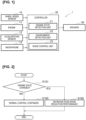
- the noise control device 1 is installed in a vehicle. As shown in Figure 1 , the noise control device 1 includes a wheel speed sensor 10, an engine 11, an acceleration sensor 12, a microphone 13, a controller 20, and a speaker 30.
- the wheel speed sensor 10 detects the rotational speed of each tire and outputs a signal indicating the detected rotational speed to the controller 20.
- an engine mounted in a vehicle is used to drive the tires.
- the engine 11 according to the present embodiment will be described as only being used for the generation of electrical power. That is, the engine 11 according to the present embodiment is not connected to the tires but to a generator (not shown).
- the engine 11 turns the generator, generating electrical power.
- the engine is not limited in this way. As is usually the case, the engine 11 may be connected to the tires.
- the term "connected” as used here may also mean "indirectly connected” or “directly connected.”
- the engine 11 outputs signals to the controller 20 indicating its own state.
- the state of the engine 11 includes, for example, a rotational speed of the engine 11, a state in which the engine 11 will start in the near future, and a state in which the engine 11 will stop in the near future.
- the signals output by the engine 11 to the controller 20 include a signal indicating the rotational speed of the engine 11, a signal indicating that the engine 11 will start in the near future, and a signal indicating that the engine 11 will stop in the near future.
- a plurality of acceleration sensors 12 are installed.
- the installation locations of the acceleration sensors 12 are not particularly limited, and may be at or near the tires and at or near the engine 11, for example.
- the acceleration sensors 12 detect vibrations from the road surface.
- the acceleration sensors 12 output the detected vibration data to the controller 20.
- the acceleration sensors 12 installed at or near the engine 11 detect the acceleration (vibration) of the engine 11. The greater the output and rotational speed of the engine 11, the greater the vibration of the engine 11. The greater the vibration of the engine 11, the greater the noise from the engine 11.
- the acceleration sensors 12 output the detected acceleration of the engine 11 to the controller 20.
- a plurality of the microphones 13 are installed in the vehicle interior.
- the installation locations of the microphones 13 are not particularly limited, and may be on the ceiling or the seats (headrests) of the vehicle, for example.
- the sound input to the microphones 13 is converted into electronic signals and output to the controller 20 as sound data.
- the microphones 13 installed on the ceiling, seats, etc., in the vehicle interior detect noise from the engine 11.
- the controller 20 is a general-purpose microcomputer that includes a CPU, memory, and an input/output unit.
- a computer program for serving as function as a noise control device 1 is installed in the microcomputer. Through execution of the computer program, the microcomputer functions as a plurality of information processing circuits included in the noise control device 1. Shown now is an example of realizing a plurality of the information processing circuits included in the noise control device 1 using software, but of course the information processing circuits can also be configured by preparing dedicated hardware to execute each of the following information processes shown below.
- the plurality of information processing circuits can also be configured in discrete hardware.
- the controller 20 includes an engine state detection unit 21, an environment detection unit 22, and a noise control unit 23 as examples of the plurality of information processing circuits.
- the engine state detection unit 21 detects the state of the engine 11 using data obtained from the wheel speed sensor 10, the engine 11, the acceleration sensor 12, and the microphone 13. Examples of the state of the engine 11 were described above.
- the engine state detection unit 21 outputs a signal in accordance with the state of the engine 11 to the noise control unit 23.
- the environment detection unit 22 detects the environment of the vehicle using data obtained from the wheel speed sensor 10, the engine 11, the acceleration sensor 12, and the microphone 13.
- the "environment of the vehicle" in the present embodiment will be described below.
- the environment detection unit 22 outputs a signal in accordance with the environment of the vehicle to the noise control unit 23.
- the noise control unit 23 analyzes the vibration data obtained from the acceleration sensor 12 and the sound data obtained from the microphone 13. The noise control unit 23 generates a sound signal of opposite phase to the analyzed vibration data and the sound data. The noise control unit 23 outputs the generated sound signal from the speaker 30. This reduces the noise since the noise is cancelled by the out-of-phase waveforms. Such a method of noise control is called “active noise control,” a well-known technology. “Active noise control” may be simply abbreviated as “ANC” below.
- the noise control unit 23 changes the performance of ANC based on signals obtained from the engine state detection unit 21 or the environment detection unit 22.
- Step S101 the engine state detection unit 21 determines whether the state of the engine 11 has changed. If the engine state detection unit 21 determines that the state of the engine 11 has changed, the detection unit outputs a signal related to the determination to the noise control unit 23 (YES in Step S101). If, on the other hand, the engine state detection unit 21 determines that the state of the engine 11 has not changed, the detection unit outputs a signal related to the determination to the noise control unit 23 (NO in Step S101).
- Step S103 the noise control unit 23 implements normal noise control.
- An example of the "normal noise control” is ANC itself.
- Step S 105 the noise control unit 23ecreases the road noise reduction performance.
- “Road noise” is the noise caused by vibrations input from the road surface. More specifically, "road noise” is the noise generated by the friction and impact between the tires and the road surface while the vehicle is traveling. In the present embodiment, ANC reduces this "road noise.”
- the acceleration sensor 12 is primarily used to detect vibrations related to "road noise.”
- To “decrease road noise reduction performance” means to decrease the performance for reducing "road noise” (i.e., to diminish the effect of ANC). As a specific example, this means suppressing the opposite phase sound output from the speaker 30.
- “Suppressing the opposite phase sound” means decreasing the amplitude of the sound output from the speaker 30 or changing the amplitude and frequency of the sound output from the speaker 30 from the state in which the effect of ANC is maximum. Suppressing the sound output from the speaker 30 in this way diminishes the effect of ANC and the interior noise of the vehicle becomes more pronounced.
- the starting sound (noise) of the engine 11 becomes drowned out by the interior noise of the vehicle, making it difficult for the passengers to notice the noise from the engine 11.
- Another effect is that the passengers are less likely to notice that the engine 11 has started.
- the engine 11 according to this embodiment is only used to generate electrical power. Therefore, as long as the battery has a sufficient SOC (STATE OF CHARGE), whether or not the engine 11 has started has little effect on the passengers. Therefore, in order to provide the passengers with a comfortable driving environment, it is necessary to make the noise from the engine 11 less noticeable to the passengers. This is achieved by means of the present embodiment.
- An example of the "change of state of the engine 11" in Step S101 shown in Figure 2 is the rotational speed of the engine 11.
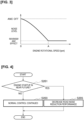
- the noise control unit 23 decreases the road noise reduction performance when the rotational speed of the engine 11 changes between 0 and a prescribed rotational speed. This is explained with reference to Figure 3 .
- the horizontal axis in Figure 3 indicates the rotational speed of the engine 11, and the vertical axis indicates the noise level of the vehicle interior.
- the interior noise level of the vehicle increases as one moves up the graph.
- ANC OFF means that ANC is not functioning. When ANC is not functioning, the noise level of the vehicle interior will, of course, be louder.
- Maximum ANC effect means that the effect of ANC is at its maximum.
- Normal control in Step S103 can be referred to "maximum ANC effect.”
- the noise control unit 23 decreases the road noise reduction performance in response to the rotational speed. For example, at the exact time the engine 11 starts, the noise control unit 23 stops ANC. As the rotational speed of the engine 11 gradually increases, the noise control unit 23 decreases the amount of reduction. When the rotational speed of the engine 11 reaches a prescribed rotational speed A, the noise control unit 23 returns ANC to normal operation.
- Step S101 An example of the "change of state of engine 11" in Step S101 shown in Figure 2 is not limited to the rotational speed of the engine 11.
- the "change of state of engine 11" in Step S101 may indicate that the engine 11 will change to a state in which the engine will start up in the near future. This will be explained with reference to Figures 4 and 5 .
- the engine state detection unit 21 determines whether the engine 11 is in a state in which the engine will start up in the near future. A signal output from the engine 11 is used for this determination.
- Step S201 If the engine state detection unit 21 acquires a signal from the engine 11 indicating that the engine 11 will start up in the near future, the engine state detection unit determines that the engine 11 has changed to a state in which the engine will start up in the near future (YES in Step S201). The process then proceeds to Step S205. If the determination result is NO in Step S201, the process proceeds to Step S203. Since the processing in Steps S203 and S205 is the same as that in Steps S103 and S105, the description of these steps will be omitted.
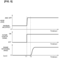
- Time T1 shown in Figure 5 indicates the time when the engine state detection unit 21 acquires a signal from the engine 11 indicating that the engine will start up in the near future.
- Time T2 indicates the time when the engine 11 starts.
- the noise control unit 23 decreases the road noise reduction performance before the engine 11 starts.
- the startup sound of the engine 11 becomes drowned out by the interior noise of the vehicle, making it difficult for the passengers to notice the noise from the engine 11.
- the noise control unit 23 stops ANC directly after time T1, but the present invention is not limited in this way.
- the "change of state of engine 11" in Step S101 shown in Figure 2 may include a change in the data detected by the acceleration sensor 12 or the microphone 13.
- the acceleration sensor 12 detects the acceleration (vibration) of the engine 11.
- the microphone 13 detects the noise from the engine 11.
- the engine state detection unit 21 determines whether the data detected by the acceleration sensor 12 or the microphone 13 exceeds a prescribed value. If the data detected by the acceleration sensor 12 or the microphone 13 exceeds the prescribed value, the noise control unit 23 may decrease the road noise reduction performance.
- the fact that the data detected by the acceleration sensor 12 or microphone 13 exceeds the prescribed value means that the engine 11 is running. Therefore, by means of this method, the passengers will less likely notice the noise from the engine 11.
- Step S301 if the engine 11 has started (YES in Step S301), the process proceeds to Step S305. If, on the other hand, the engine 11 did not start up (NO in Step S301), the process proceeds to Step S303.
- Step S305 the environment detection unit 22 detects the vehicle environment.
- the noise control unit 23 does not decrease the noise reduction performance. "Does not decrease the noise reduction performance” means that normal ANC is performed. If, on the other hand, the vehicle speed is less than the prescribed speed (NO in Step S305), the noise control unit 23 decreases the road noise reduction performance (Step S309).
- the "vehicle environment” may also include the data detected by the acceleration sensor 12 or microphone 13 immediately before the engine 11 starts. If the data detected by the acceleration sensor 12 or the microphone 13 immediately before the engine 11 starts exceeds a prescribed value, the process result in Step S305 is YES. The fact that the data detected by the acceleration sensor 12 or the microphone 13 immediately before the engine 11 starts exceeds a prescribed value indicates high road noise. Therefore, since the noise from the engine 11 becomes drowned out by the interior noise of the vehicle, there is no need to decrease the road noise reduction performance. Therefore, if the data detected by the acceleration sensor 12 or the microphone 13 immediately before the engine 11 starts exceeds the respective prescribed values, the noise control unit 23 does not decrease the noise reduction performance. If the data detected by the acceleration sensor 12 or microphone 13 immediately before the engine 11 starts is less than the respective prescribed values (NO in Step S305), the noise control unit 23 decreases the road noise reduction performance (Step S309).
- Step S407 the noise control unit 23 outputs sound from the speaker 30.
- the road noise reduction performance is decreased.
- the effect would be limited (the road noise would not be very loud). In this case, it is less likely that the startup sound of the engine 11 would be drowned out by the interior noise of the vehicle.
- Step S407 in order to drown out the startup sound of the engine 11, the noise control unit 23 would output sound from the speaker 30.
- the noise control unit 23 may output from the speaker 30 sound louder than the road noise.
- the amplitude and frequency associated with the road noise are known.
- the noise control unit 23 can output from the speaker 30 sound that is louder than the road noise.
- the process of Step S407 may be expressed as outputting sound from the speaker 30 that is louder than the road noise.
- Time T1 in Figure 10 indicates the time when the road noise reduction performance begins to be decreased.
- Time T2 indicates the time when ANC is stopped.
- the noise control unit 23 gradually decreases the road noise reduction performance and then stops the road noise reduction performance while simultaneously outputting sound from the speaker 30.
- Reference designator 50 indicates that the interior noise level of the vehicle has increased caused by the sound output. By increasing the interior noise level of the vehicle by outputting sound in this manner, the startup sound of the engine 11 can be drowned out.
- the "change of state of engine 11" in Step S101 shown in Figure 2 may include an abnormality of the engine 11.
- "abnormal” means not normal.
- the idea of "abnormality” here includes not only failures that prevent constituent parts from executing the original functions thereof, but also defects that do not lead to failures or signs of failure. Processing when an abnormality of the engine 11 is detected will be described with reference to Figure 11 . If an abnormality of the engine 11 is detected, a command to stop ANC is output (YES in Step S501). In Step S505, the noise control unit 23 outputs sound from the speaker 30. The method of outputting sound is the same as that of Figure 9 . In this way, passengers can be notified that an abnormality of the engine 11 has occurred.
- Step S507 the noise control unit 23 stops ANC.
- the process shown in Figure 11 is not limited to abnormalities of the engine 11.
- the vehicle is provided with other equipment. More specifically, such equipment includes the generator, motor, inverter, battery, ANC system, etc. If an abnormality of the equipment or in the operation thereof is detected, the same process is performed as that used when an abnormality of the engine 11 is detected. Such a process is based on a fail-safe perspective.
- the noise control unit 23 may notify the occupant (user in the vehicle) of ANC stop guidance.
- the stop guidance may be displayed on a display (e.g., a display of a navigation device) or output as a voice from the speaker 30.
- a passenger may stop ANC by pressing a virtual switch that appears on the display or a physical switch installed in the vehicle.
- the noise control device 1 provides the following operation and effects.
- the noise control device 1 includes the engine 11 mounted in the vehicle and the controller 20 that detects the state of the engine 11.
- the controller 20 decreases the performance for reducing noise caused by the vibrations input from the road surface in accordance with the state of the engine 11.
- An example of the "noise caused by the vibrations input from the road surface” is the “road noise” described above.
- the noise control device 1 the noise from the engine 11 is drowned out by the interior noise of the vehicle, thereby making it less likely that the passengers will notice the noise from the engine 11.
- the "noise from the engine 11” includes the “startup sound of the engine 11" and “driving sound of the engine 11.” Another effect is that the passengers are less likely to notice that the engine 11 has started.
- the state of the engine 11 includes the rotational speed of the engine 11.
- the controller 20 decreases the noise reduction performance when the speed of the engine 11 reaches a prescribed rotational speed.
- An example of a "prescribed rotational speed” is "prescribed rotational speed B.”
- the noise control device 1 By means of the noise control device 1, the noise from the engine 11 is drowned out by the interior noise of the vehicle, thereby making it less likely that the passengers will notice the noise from the engine 11.
- the state of the engine 11 includes a state in which the engine 11 will start in the near future.
- the controller 20 receives a signal indicating that the engine 11 will start in the near future, the controller decreases the noise reduction performance. In this way, the startup sound of the engine 11 becomes drowned out by the interior noise of the vehicle, thereby making it less likely that the passengers will notice the noise from the engine 11.
- the controller 20 When the controller 20 receives a signal indicating that the engine 11 will start in the near future, the controller gradually decreases the noise reduction performance before the engine 11 starts, and, then immediately before the engine 11 starts, stops the noise reduction performance. In this way, the road noise can be reduced until just before the engine 11 starts. Since the startup sound of the engine 11 then becomes drowned out by the interior noise of the vehicle, the passengers will be less likely to notice the noise from the engine 11.
- the state of the engine 11 includes the vibration data detected by the acceleration sensor 12 or the noise data detected by the microphone 13.
- the controller 20 decreases the noise reduction performance. In this way, the noise from the engine 11 is drowned out by the interior noise of the vehicle, thereby making it less likely that the passengers will notice the noise from the engine 11.
- the controller 20 decreases the noise reduction performance when the noise level associated with a prescribed frequency, from among the frequencies indicated by the vibration data related to the engine 11 or the noise data related to the engine 11, exceeds a prescribed value. In this way, the noise from the engine 11 is drowned out by the interior noise of the vehicle, thereby making it less likely that the passengers will notice the noise from the engine 11.
- the controller 20 detects the vehicle environment.
- the controller 20 does not decrease the noise reduction performance in accordance with the detected vehicle environment after the engine 11 starts. This is because the noise from the engine 11 will be drowned out by the interior noise of the vehicle when the interior noise level of the vehicle is already high.
- the vehicle environment includes the vehicle speed. If the vehicle speed exceeds a prescribed speed after the engine 11 starts, the controller 20 does not decrease noise reduction performance. That the vehicle speed exceeds the prescribed speed indicates a high level of road noise. Since the noise from the engine 11 is drowned out by the interior noise of the vehicle, there is no need to decrease road noise reduction performance.
- the vehicle environment includes the vibration data detected by the acceleration sensor 12 or the noise data detected by the microphone 13. If the noise level indicated by the vibration data or the noise data detected immediately before the engine 11 starts exceeds a prescribed value, the controller 20 does not decrease noise reduction performance. That these noise levels exceed the prescribed value indicates a high level of road noise. Since the noise from the engine 11 is drowned out by the interior noise of the vehicle, there is no need to decrease road noise reduction performance.
- “Vibration data” here means “vibration data that excludes the engine 11.”
- noisese data here means “noise data that excludes engine 11.”
- the controller 20 decreases the noise reduction performance in accordance with the state of the engine 11 and then stops the noise reduction performance while simultaneously outputting sound from the speaker 30. In this way, it is possible to drown out the noise from the engine 11.
- controller 20 If an abnormality of the equipment installed in the vehicle or in the operation of the equipment is detected, a command to stop the noise reduction performance is output to controller 20.
- the controller 20 receives the command, the controller stops the noise reduction performance after outputting sound from the speaker 30, or provides noise reduction performance stop guidance to the passengers after outputting sound from the speaker 30. In this way, the passengers can be notified that an abnormality of the equipment or in the operation of the equipment has occurred.
- the processing circuits include programmed processing devices, such as processing devices comprising electrical circuitry.
- the processing circuits also include devices such as application-specific integrated circuits (ASICs) and circuit components arranged to perform the described functions.
- ASICs application-specific integrated circuits
- Time T1 in Figure 12 indicates the time at which the engine 11 starts.
- Time T2 indicates the time at which the engine 11 transitions to steady state.
- the period between time T1 and time T2 indicates the time from the starting of the engine 11 until the transition to steady state.
- “Steady state” refers to a state in which the rotational speed of the engine 11 is maintained at a constant speed.
- “Steady state” may also be expressed as a state in which the temporal variation in the rotational speed of the engine 11 is less than a prescribed value.
- the controller 20 reduces the noise related to the engine 11 when the engine 11 starts, and reduces the noise caused by the vibration input from the road surface when the engine 11 stops.
- the controller 20 reduces the noise caused by the vibration input from the road surface until time T1.
- the controller 20 reduces the noise related to the engine 11 after time T2.
- road noise is reduced until the engine 11 starts, and noise related to the engine 11 is reduced after the engine 11 starts.
- the engine 11 may transition to steady state and then the engine 11 may continue to operate.
- Time T1 in Figure 13 indicates the time at which the engine 11 starts.
- Time T2 is an arbitrary time point indicating that the engine 11 continues to operate after having transitioned to steady state.
- the controller 20 detects temporal variations in the rotational speed of the engine 11. When the temporal variation in the rotational speed of the engine 11 is less than a prescribed value and the engine 11 is in operation, the controller 20 does not reduce the noise caused by the vibration input from the road surface but only the noise related to the engine 11. The passengers will thereby be less likely to notice the noise from the engine 11.
- That "engine 11 is stopped” may be taken to mean that the rotational speed of the engine 11 is zero.
- “Noise related to the engine 11” may be defined as noise indicated by the data detected by the acceleration sensor 12 or the microphone 13 installed in the engine 11.
- “Noise caused by the vibration input from the road surface” may be defined as the noise indicated by the data detected by the acceleration sensor 12 or the microphone 13 installed at locations other than the engine 11.
- the controller 20 may not reduce the noise related to the engine 11, but may reduce the noise caused by the vibration input from the road surface. This effectively reduces road noise.
- the controller 20 may reduce the noise related to the engine 11 using, of the data detected by the plurality of acceleration sensors 12, only the data detected by the acceleration sensors 12 installed in the engine 11. The passengers will thereby be less likely to notice the noise from the engine 11.
- ANC only the data from the acceleration sensor 12, only the data from the microphone 13, or both the data from the acceleration sensor 12 and the microphone 13 may be used.
- noise control device 10 wheel speed sensor, 11 engine, 12 acceleration sensor, 13 microphone, 20 control unit, 21 engine state detection unit, 22 environment detection unit, 23 noise controller, 30 speaker
Landscapes
- Engineering & Computer Science (AREA)
- Physics & Mathematics (AREA)
- Acoustics & Sound (AREA)
- Multimedia (AREA)
- Mechanical Engineering (AREA)
- Soundproofing, Sound Blocking, And Sound Damping (AREA)
- Fittings On The Vehicle Exterior For Carrying Loads, And Devices For Holding Or Mounting Articles (AREA)
Abstract
Description
- The present invention relates to a noise control method and a noise control device.
- Inventions for reducing noise (primarily road noise) in the interior of a vehicle are known from the prior art (Patent Document 1). The invention described in
Patent Document 1 stops adaptive action of an adaptive controller when the changes of transfer function from a noise source to an evaluation point are determined to exceed a specified state. - Patent Document 1:
Japanese Laid-Open Patent Application No. 5-158487 - According to the invention described in
Patent Document 1, the interior noise of a vehicle is reduced. However, if the engine starts while the interior noise of the vehicle is reduced, the engine noise will be emphasized, which may cause passengers to feel uncomfortable. - The present invention was conceived in light of the problem described above, and an object thereof is to provide a noise control method and a noise control device that make the engine noise less noticeable to the passengers.
- The noise control method according to one aspect of the present invention decreases performance for reducing noise caused by the vibration from the road surface as a function of the state of the engine.
- By means of the present invention, it will be less likely that the passengers will notice engine noise.
-
-
Figure 1 shows an example of the configuration of anoise control device 1 according to an embodiment of the present invention. -
Figure 2 shows a flowchart illustrating an example of the operation of thenoise control device 1. -
Figure 3 shows a graph illustrating the relationship between engine speed and noise level. -
Figure 4 shows a flowchart illustrating another example of the operation of thenoise control device 1. -
Figure 5 shows graphs illustrating an example of timing for decreasing road noise reduction performance. -
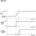
Figure 6 shows graphs illustrating another example of timing for decreasing the road noise reduction performance. -
Figure 7 shows a graph illustrating the relationship between frequency and noise level. -
Figure 8 shows a flowchart illustrating another example of the operation of thenoise control device 1. -
Figure 9 shows a flowchart illustrating another example of the operation of thenoise control device 1. -
Figure 10 shows a graph illustrating an example of sound output timing. -
Figure 11 shows a flowchart illustrating another example of the operation of thenoise control device 1. -
Figure 12 shows another example of the operation of thenoise control device 1. -
Figure 13 shows another example of the operation of thenoise control device 1. -
Figure 14 shows another graph illustrating the relationship between frequency and noise level. - Embodiments of the present invention will be described below with reference to the drawings. In the description of the drawings, the same parts have been assigned the same reference numerals and the descriptions thereof are not repeated.
- An example of the configuration of a
noise control device 1 is described below with reference toFigure 1 . Thenoise control device 1 is installed in a vehicle. As shown inFigure 1 , thenoise control device 1 includes awheel speed sensor 10, anengine 11, anacceleration sensor 12, amicrophone 13, acontroller 20, and aspeaker 30. - The
wheel speed sensor 10 detects the rotational speed of each tire and outputs a signal indicating the detected rotational speed to thecontroller 20. - In general, an engine mounted in a vehicle is used to drive the tires. However, the
engine 11 according to the present embodiment will be described as only being used for the generation of electrical power. That is, theengine 11 according to the present embodiment is not connected to the tires but to a generator (not shown). Theengine 11 turns the generator, generating electrical power. However, the engine is not limited in this way. As is usually the case, theengine 11 may be connected to the tires. The term "connected" as used here may also mean "indirectly connected" or "directly connected." Theengine 11 outputs signals to thecontroller 20 indicating its own state. The state of theengine 11 includes, for example, a rotational speed of theengine 11, a state in which theengine 11 will start in the near future, and a state in which theengine 11 will stop in the near future. The signals output by theengine 11 to thecontroller 20 include a signal indicating the rotational speed of theengine 11, a signal indicating that theengine 11 will start in the near future, and a signal indicating that theengine 11 will stop in the near future. - A plurality of
acceleration sensors 12 are installed. The installation locations of theacceleration sensors 12 are not particularly limited, and may be at or near the tires and at or near theengine 11, for example. As the vehicle travels, theacceleration sensors 12 detect vibrations from the road surface. Theacceleration sensors 12 output the detected vibration data to thecontroller 20. Theacceleration sensors 12 installed at or near theengine 11 detect the acceleration (vibration) of theengine 11. The greater the output and rotational speed of theengine 11, the greater the vibration of theengine 11. The greater the vibration of theengine 11, the greater the noise from theengine 11. Theacceleration sensors 12 output the detected acceleration of theengine 11 to thecontroller 20. - A plurality of the
microphones 13 are installed in the vehicle interior. The installation locations of themicrophones 13 are not particularly limited, and may be on the ceiling or the seats (headrests) of the vehicle, for example. The sound input to themicrophones 13 is converted into electronic signals and output to thecontroller 20 as sound data. Themicrophones 13 installed on the ceiling, seats, etc., in the vehicle interior detect noise from theengine 11. - The
controller 20 is a general-purpose microcomputer that includes a CPU, memory, and an input/output unit. A computer program for serving as function as anoise control device 1 is installed in the microcomputer. Through execution of the computer program, the microcomputer functions as a plurality of information processing circuits included in thenoise control device 1. Shown now is an example of realizing a plurality of the information processing circuits included in thenoise control device 1 using software, but of course the information processing circuits can also be configured by preparing dedicated hardware to execute each of the following information processes shown below. The plurality of information processing circuits can also be configured in discrete hardware. Thecontroller 20 includes an enginestate detection unit 21, anenvironment detection unit 22, and anoise control unit 23 as examples of the plurality of information processing circuits. - The engine
state detection unit 21 detects the state of theengine 11 using data obtained from thewheel speed sensor 10, theengine 11, theacceleration sensor 12, and themicrophone 13. Examples of the state of theengine 11 were described above. The enginestate detection unit 21 outputs a signal in accordance with the state of theengine 11 to thenoise control unit 23. - The
environment detection unit 22 detects the environment of the vehicle using data obtained from thewheel speed sensor 10, theengine 11, theacceleration sensor 12, and themicrophone 13. The "environment of the vehicle" in the present embodiment will be described below. Theenvironment detection unit 22 outputs a signal in accordance with the environment of the vehicle to thenoise control unit 23. - The
noise control unit 23 analyzes the vibration data obtained from theacceleration sensor 12 and the sound data obtained from themicrophone 13. Thenoise control unit 23 generates a sound signal of opposite phase to the analyzed vibration data and the sound data. Thenoise control unit 23 outputs the generated sound signal from thespeaker 30. This reduces the noise since the noise is cancelled by the out-of-phase waveforms. Such a method of noise control is called "active noise control," a well-known technology. "Active noise control" may be simply abbreviated as "ANC" below. Thenoise control unit 23 changes the performance of ANC based on signals obtained from the enginestate detection unit 21 or theenvironment detection unit 22. - Next, an example of the operation of the
noise control device 1 is described with reference toFigure 2 . In Step S101, the enginestate detection unit 21 determines whether the state of theengine 11 has changed. If the enginestate detection unit 21 determines that the state of theengine 11 has changed, the detection unit outputs a signal related to the determination to the noise control unit 23 (YES in Step S101). If, on the other hand, the enginestate detection unit 21 determines that the state of theengine 11 has not changed, the detection unit outputs a signal related to the determination to the noise control unit 23 (NO in Step S101). In Step S103, thenoise control unit 23 implements normal noise control. An example of the "normal noise control" is ANC itself. InStep S 105, the noise control unit 23ecreases the road noise reduction performance. "Road noise" is the noise caused by vibrations input from the road surface. More specifically, "road noise" is the noise generated by the friction and impact between the tires and the road surface while the vehicle is traveling. In the present embodiment, ANC reduces this "road noise." - The
acceleration sensor 12 is primarily used to detect vibrations related to "road noise." To "decrease road noise reduction performance" means to decrease the performance for reducing "road noise" (i.e., to diminish the effect of ANC). As a specific example, this means suppressing the opposite phase sound output from thespeaker 30. "Suppressing the opposite phase sound" means decreasing the amplitude of the sound output from thespeaker 30 or changing the amplitude and frequency of the sound output from thespeaker 30 from the state in which the effect of ANC is maximum. Suppressing the sound output from thespeaker 30 in this way diminishes the effect of ANC and the interior noise of the vehicle becomes more pronounced. Thus, the starting sound (noise) of theengine 11 becomes drowned out by the interior noise of the vehicle, making it difficult for the passengers to notice the noise from theengine 11. Another effect is that the passengers are less likely to notice that theengine 11 has started. Theengine 11 according to this embodiment is only used to generate electrical power. Therefore, as long as the battery has a sufficient SOC (STATE OF CHARGE), whether or not theengine 11 has started has little effect on the passengers. Therefore, in order to provide the passengers with a comfortable driving environment, it is necessary to make the noise from theengine 11 less noticeable to the passengers. This is achieved by means of the present embodiment. - An example of the "change of state of the
engine 11" in Step S101 shown inFigure 2 is the rotational speed of theengine 11. Thenoise control unit 23 decreases the road noise reduction performance when the rotational speed of theengine 11 changes between 0 and a prescribed rotational speed. This is explained with reference toFigure 3 . The horizontal axis inFigure 3 indicates the rotational speed of theengine 11, and the vertical axis indicates the noise level of the vehicle interior. The interior noise level of the vehicle increases as one moves up the graph. "ANC OFF" means that ANC is not functioning. When ANC is not functioning, the noise level of the vehicle interior will, of course, be louder. "Maximum ANC effect" means that the effect of ANC is at its maximum. When the ANC effect is maximum, the interior noise level of the vehicle will be low. "Normal control" in Step S103 can be referred to "maximum ANC effect." As shown inFigure 3 , when the rotational speed of theengine 11 changes between 0 and a prescribed rotational speed, thenoise control unit 23 decreases the road noise reduction performance in response to the rotational speed. For example, at the exact time theengine 11 starts, thenoise control unit 23 stops ANC. As the rotational speed of theengine 11 gradually increases, thenoise control unit 23 decreases the amount of reduction. When the rotational speed of theengine 11 reaches a prescribed rotational speed A, thenoise control unit 23 returns ANC to normal operation. In other words, when the rotational speed of theengine 11 is below the prescribed rotational speed A, thenoise control unit 23 decreases the road noise reduction performance. Thenoise control unit 23 may also set a prescribed rotational speed B between 0 and A and decrease the road noise reduction performance when the rotational speed of theengine 11 reaches B. Thenoise control unit 23 may also set a prescribed rotational speed C and a prescribed rotational speed D (C < D) between 0 and A and decrease the road noise reduction performance when the rotational speed of theengine 11 is between C and D. - An example of the "change of state of
engine 11" in Step S101 shown inFigure 2 is not limited to the rotational speed of theengine 11. The "change of state ofengine 11" in Step S101 may indicate that theengine 11 will change to a state in which the engine will start up in the near future. This will be explained with reference toFigures 4 and5 . In Step S201 ofFigure 4 , the enginestate detection unit 21 determines whether theengine 11 is in a state in which the engine will start up in the near future. A signal output from theengine 11 is used for this determination. If the enginestate detection unit 21 acquires a signal from theengine 11 indicating that theengine 11 will start up in the near future, the engine state detection unit determines that theengine 11 has changed to a state in which the engine will start up in the near future (YES in Step S201). The process then proceeds to Step S205. If the determination result is NO in Step S201, the process proceeds to Step S203. Since the processing in Steps S203 and S205 is the same as that in Steps S103 and S105, the description of these steps will be omitted. As used here, the "near future" is not particularly limited, but can be, for example, imminently in 5 seconds Time T1 shown inFigure 5 indicates the time when the enginestate detection unit 21 acquires a signal from theengine 11 indicating that the engine will start up in the near future. Time T2 indicates the time when theengine 11 starts. As shown, at time T1, thenoise control unit 23 decreases the road noise reduction performance before theengine 11 starts. Thus, as shown at time T2, the startup sound of theengine 11 becomes drowned out by the interior noise of the vehicle, making it difficult for the passengers to notice the noise from theengine 11. Note that inFigure 5 , thenoise control unit 23 stops ANC directly after time T1, but the present invention is not limited in this way. For example, as shown inFigure 6 , thenoise control unit 23 may gradually decrease the road noise reduction performance from time T1 to time T2 and may stop ANC immediately before theengine 11 starts (time T2). Thus, compared toFigure 5 , it is possible to reduce the interior noise of the vehicle between time T1 and time T2. An example of a time when the device installed in the vehicle starts theengine 11 is when the SOC of the battery falls below a prescribed value. - The "change of state of
engine 11" in Step S101 shown inFigure 2 may include a change in the data detected by theacceleration sensor 12 or themicrophone 13. Theacceleration sensor 12 detects the acceleration (vibration) of theengine 11. Themicrophone 13 detects the noise from theengine 11. The enginestate detection unit 21 determines whether the data detected by theacceleration sensor 12 or themicrophone 13 exceeds a prescribed value. If the data detected by theacceleration sensor 12 or themicrophone 13 exceeds the prescribed value, thenoise control unit 23 may decrease the road noise reduction performance. The fact that the data detected by theacceleration sensor 12 ormicrophone 13 exceeds the prescribed value means that theengine 11 is running. Therefore, by means of this method, the passengers will less likely notice the noise from theengine 11. Note that, as shown inFigure 7 , if the noise level associated with a specific frequency (the 1.5th order component of the engine 11), from among the frequencies associated with acceleration or noise, exceeds the noise level indicated byreference indicator 40, thenoise control unit 23 may decrease the road noise reduction performance. - Another example of the operation of the
noise control device 1 will now be described with reference toFigure 8 . However, since the process of Steps S303 and S307 is the same as that of Step S103 shown inFigure 2 , the description of these steps will not be repeated. Further, since the process of Step S309 is the same as that of Step S105 shown inFigure 2 , the description of this step will not be repeated. In Step S301, if theengine 11 has started (YES in Step S301), the process proceeds to Step S305. If, on the other hand, theengine 11 did not start up (NO in Step S301), the process proceeds to Step S303. In Step S305, theenvironment detection unit 22 detects the vehicle environment. If the vehicle environment is a prescribed environment (YES in Step S305), the process proceeds to Step S307. If, on the other hand, the vehicle environment is not a prescribed environment (NO in Step S305), the process proceeds to Step S309. Here, an example of "vehicle environment" will now be explained. An example of a "vehicle environment" is vehicle speed. If the vehicle speed exceeds a prescribed speed, the process result in Step S305 is YES. A vehicle speed greater than the prescribed speed indicates high road noise. In this case, the interior noise of the vehicle will be high, even with ANC. Thus, since the noise from theengine 11 becomes drowned out by the interior noise of the vehicle, there is no need to decrease the road noise reduction performance. Therefore, if the vehicle speed exceeds the prescribed speed, thenoise control unit 23 does not decrease the noise reduction performance. "Does not decrease the noise reduction performance" means that normal ANC is performed. If, on the other hand, the vehicle speed is less than the prescribed speed (NO in Step S305), thenoise control unit 23 decreases the road noise reduction performance (Step S309). - The "vehicle environment" may also include the data detected by the
acceleration sensor 12 ormicrophone 13 immediately before theengine 11 starts. If the data detected by theacceleration sensor 12 or themicrophone 13 immediately before theengine 11 starts exceeds a prescribed value, the process result in Step S305 is YES. The fact that the data detected by theacceleration sensor 12 or themicrophone 13 immediately before theengine 11 starts exceeds a prescribed value indicates high road noise. Therefore, since the noise from theengine 11 becomes drowned out by the interior noise of the vehicle, there is no need to decrease the road noise reduction performance. Therefore, if the data detected by theacceleration sensor 12 or themicrophone 13 immediately before theengine 11 starts exceeds the respective prescribed values, thenoise control unit 23 does not decrease the noise reduction performance. If the data detected by theacceleration sensor 12 ormicrophone 13 immediately before theengine 11 starts is less than the respective prescribed values (NO in Step S305), thenoise control unit 23 decreases the road noise reduction performance (Step S309). - Another example of the operation of the
noise control device 1 will now be described with reference toFigure 9 . However, since the process of Steps S401 to S405 is the same as that of Steps S101 to S105 shown inFigure 2 , the description of these steps will not be repeated. In Step S407, thenoise control unit 23 outputs sound from thespeaker 30. As a result of the process of Step S405, the road noise reduction performance is decreased. However, for example, if there were a small amount of road noise, even if the road noise reduction performance were decreased, the effect would be limited (the road noise would not be very loud). In this case, it is less likely that the startup sound of theengine 11 would be drowned out by the interior noise of the vehicle. In other words, the passengers would be more likely to notice the noise from theengine 11. Therefore, in Step S407, in order to drown out the startup sound of theengine 11, thenoise control unit 23 would output sound from thespeaker 30. Thus, it is possible to drown out the startup sound of theengine 11. As to what type of sound to output, for example, thenoise control unit 23 may output from thespeaker 30 sound louder than the road noise. Through analysis of the vibration acquired from theacceleration sensor 12, the amplitude and frequency associated with the road noise are known. By using sound of greater amplitude than the amplitude associated with the road noise, thenoise control unit 23 can output from thespeaker 30 sound that is louder than the road noise. The process of Step S407 may be expressed as outputting sound from thespeaker 30 that is louder than the road noise. An example of the timing for outputting the sound will be described with reference toFigure 10 . Time T1 inFigure 10 indicates the time when the road noise reduction performance begins to be decreased. Time T2 indicates the time when ANC is stopped. As shown inFigure 10 , thenoise control unit 23 gradually decreases the road noise reduction performance and then stops the road noise reduction performance while simultaneously outputting sound from thespeaker 30.Reference designator 50 indicates that the interior noise level of the vehicle has increased caused by the sound output. By increasing the interior noise level of the vehicle by outputting sound in this manner, the startup sound of theengine 11 can be drowned out. - The "change of state of
engine 11" in Step S101 shown inFigure 2 may include an abnormality of theengine 11. In the present embodiment, "abnormal" means not normal. The idea of "abnormality" here includes not only failures that prevent constituent parts from executing the original functions thereof, but also defects that do not lead to failures or signs of failure. Processing when an abnormality of theengine 11 is detected will be described with reference toFigure 11 . If an abnormality of theengine 11 is detected, a command to stop ANC is output (YES in Step S501). In Step S505, thenoise control unit 23 outputs sound from thespeaker 30. The method of outputting sound is the same as that ofFigure 9 . In this way, passengers can be notified that an abnormality of theengine 11 has occurred. In Step S507, thenoise control unit 23 stops ANC. The process shown inFigure 11 is not limited to abnormalities of theengine 11. In addition to theengine 11, the vehicle is provided with other equipment. More specifically, such equipment includes the generator, motor, inverter, battery, ANC system, etc. If an abnormality of the equipment or in the operation thereof is detected, the same process is performed as that used when an abnormality of theengine 11 is detected. Such a process is based on a fail-safe perspective. Note that in Step S507, instead of stopping ANC, thenoise control unit 23 may notify the occupant (user in the vehicle) of ANC stop guidance. The stop guidance may be displayed on a display (e.g., a display of a navigation device) or output as a voice from thespeaker 30. Upon receiving the stop guidance, a passenger may stop ANC by pressing a virtual switch that appears on the display or a physical switch installed in the vehicle. - As explained above, the
noise control device 1 according to the present embodiment provides the following operation and effects. - The
noise control device 1 includes theengine 11 mounted in the vehicle and thecontroller 20 that detects the state of theengine 11. Thecontroller 20 decreases the performance for reducing noise caused by the vibrations input from the road surface in accordance with the state of theengine 11. An example of the "noise caused by the vibrations input from the road surface" is the "road noise" described above. By means of thenoise control device 1, the noise from theengine 11 is drowned out by the interior noise of the vehicle, thereby making it less likely that the passengers will notice the noise from theengine 11. The "noise from theengine 11" includes the "startup sound of theengine 11" and "driving sound of theengine 11." Another effect is that the passengers are less likely to notice that theengine 11 has started. - The state of the
engine 11 includes the rotational speed of theengine 11. Thecontroller 20 decreases the noise reduction performance when the speed of theengine 11 reaches a prescribed rotational speed. An example of a "prescribed rotational speed" is "prescribed rotational speed B." By means of thenoise control device 1, the noise from theengine 11 is drowned out by the interior noise of the vehicle, thereby making it less likely that the passengers will notice the noise from theengine 11. - The state of the
engine 11 includes a state in which theengine 11 will start in the near future. When thecontroller 20 receives a signal indicating that theengine 11 will start in the near future, the controller decreases the noise reduction performance. In this way, the startup sound of theengine 11 becomes drowned out by the interior noise of the vehicle, thereby making it less likely that the passengers will notice the noise from theengine 11. - When the
controller 20 receives a signal indicating that theengine 11 will start in the near future, the controller gradually decreases the noise reduction performance before theengine 11 starts, and, then immediately before theengine 11 starts, stops the noise reduction performance. In this way, the road noise can be reduced until just before theengine 11 starts. Since the startup sound of theengine 11 then becomes drowned out by the interior noise of the vehicle, the passengers will be less likely to notice the noise from theengine 11. - The state of the
engine 11 includes the vibration data detected by theacceleration sensor 12 or the noise data detected by themicrophone 13. When the noise level indicated by the vibration data related to theengine 11 or the noise level indicated by the noise data noise data related to theengine 11 exceeds a prescribed value, thecontroller 20 decreases the noise reduction performance. In this way, the noise from theengine 11 is drowned out by the interior noise of the vehicle, thereby making it less likely that the passengers will notice the noise from theengine 11. - The
controller 20 decreases the noise reduction performance when the noise level associated with a prescribed frequency, from among the frequencies indicated by the vibration data related to theengine 11 or the noise data related to theengine 11, exceeds a prescribed value. In this way, the noise from theengine 11 is drowned out by the interior noise of the vehicle, thereby making it less likely that the passengers will notice the noise from theengine 11. - The
controller 20 detects the vehicle environment. Thecontroller 20 does not decrease the noise reduction performance in accordance with the detected vehicle environment after theengine 11 starts. This is because the noise from theengine 11 will be drowned out by the interior noise of the vehicle when the interior noise level of the vehicle is already high. - The vehicle environment includes the vehicle speed. If the vehicle speed exceeds a prescribed speed after the
engine 11 starts, thecontroller 20 does not decrease noise reduction performance. That the vehicle speed exceeds the prescribed speed indicates a high level of road noise. Since the noise from theengine 11 is drowned out by the interior noise of the vehicle, there is no need to decrease road noise reduction performance. - The vehicle environment includes the vibration data detected by the
acceleration sensor 12 or the noise data detected by themicrophone 13. If the noise level indicated by the vibration data or the noise data detected immediately before theengine 11 starts exceeds a prescribed value, thecontroller 20 does not decrease noise reduction performance. That these noise levels exceed the prescribed value indicates a high level of road noise. Since the noise from theengine 11 is drowned out by the interior noise of the vehicle, there is no need to decrease road noise reduction performance. "Vibration data" here means "vibration data that excludes theengine 11." Similarly, "noise data" here means "noise data that excludesengine 11." - The
controller 20 decreases the noise reduction performance in accordance with the state of theengine 11 and then stops the noise reduction performance while simultaneously outputting sound from thespeaker 30. In this way, it is possible to drown out the noise from theengine 11. - If an abnormality of the equipment installed in the vehicle or in the operation of the equipment is detected, a command to stop the noise reduction performance is output to
controller 20. When thecontroller 20 receives the command, the controller stops the noise reduction performance after outputting sound from thespeaker 30, or provides noise reduction performance stop guidance to the passengers after outputting sound from thespeaker 30. In this way, the passengers can be notified that an abnormality of the equipment or in the operation of the equipment has occurred. - Each of the functions described in the embodiment can be implemented by one or more processing circuits. The processing circuits include programmed processing devices, such as processing devices comprising electrical circuitry. The processing circuits also include devices such as application-specific integrated circuits (ASICs) and circuit components arranged to perform the described functions.
- As described above, an embodiment of the present invention described above, but the statements and drawings that constitute part of this disclosure should not be understood as limiting the present invention. It will be apparent to those skilled in the art that various alternative embodiments, implementations, and operating techniques are possible from the present disclosure.
- Another example of the operation of the
noise control device 1 will be described with reference toFigure 12 . Time T1 inFigure 12 indicates the time at which theengine 11 starts. Time T2 indicates the time at which theengine 11 transitions to steady state. The period between time T1 and time T2 indicates the time from the starting of theengine 11 until the transition to steady state. "Steady state" refers to a state in which the rotational speed of theengine 11 is maintained at a constant speed. "Steady state" may also be expressed as a state in which the temporal variation in the rotational speed of theengine 11 is less than a prescribed value. Thecontroller 20 reduces the noise related to theengine 11 when theengine 11 starts, and reduces the noise caused by the vibration input from the road surface when theengine 11 stops. In other words, thecontroller 20 reduces the noise caused by the vibration input from the road surface until time T1. Thecontroller 20 reduces the noise related to theengine 11 after time T2. As a result, road noise is reduced until theengine 11 starts, and noise related to theengine 11 is reduced after theengine 11 starts. - The
engine 11 may transition to steady state and then theengine 11 may continue to operate. Time T1 inFigure 13 indicates the time at which theengine 11 starts. Time T2 is an arbitrary time point indicating that theengine 11 continues to operate after having transitioned to steady state. Thecontroller 20 detects temporal variations in the rotational speed of theengine 11. When the temporal variation in the rotational speed of theengine 11 is less than a prescribed value and theengine 11 is in operation, thecontroller 20 does not reduce the noise caused by the vibration input from the road surface but only the noise related to theengine 11. The passengers will thereby be less likely to notice the noise from theengine 11. When the "temporal variation in the rotational speed of theengine 11 is less than a prescribed value and theengine 11 is in operation" indicates that theengine 11 is continuously operating after having transitioned to steady state, such as at time T2.Reference designator 60 inFigure 14 indicates that theengine 11 starts and ANC stops.Reference designator 61 indicates thatengine 11 is stopped and ANC is deactivated.Reference designator code 62 indicates that ANC is in operation using all sensors.Reference designator 63 indicates that only the data detected by theacceleration sensor 12 and themicrophone 13 installed in theengine 11 are used. As indicated byreference designator 63, the interior noise level of the vehicle is reduced by reducing only the noise related to theengine 11, thereby making it less likely that the passengers will notice the noise from theengine 11. - That "
engine 11 is stopped" may be taken to mean that the rotational speed of theengine 11 is zero. "Noise related to theengine 11" may be defined as noise indicated by the data detected by theacceleration sensor 12 or themicrophone 13 installed in theengine 11. "Noise caused by the vibration input from the road surface" may be defined as the noise indicated by the data detected by theacceleration sensor 12 or themicrophone 13 installed at locations other than theengine 11. When the rotational speed of theengine 11 is zero, thecontroller 20 may not reduce the noise related to theengine 11, but may reduce the noise caused by the vibration input from the road surface. This effectively reduces road noise. - When the temporal variation in the rotational speed of the
engine 11 is less than a prescribed value and theengine 11 is in operation, thecontroller 20 may reduce the noise related to theengine 11 using, of the data detected by the plurality ofacceleration sensors 12, only the data detected by theacceleration sensors 12 installed in theengine 11. The passengers will thereby be less likely to notice the noise from theengine 11. - In ANC, only the data from the
acceleration sensor 12, only the data from themicrophone 13, or both the data from theacceleration sensor 12 and themicrophone 13 may be used. - 1 noise control device, 10 wheel speed sensor, 11 engine, 12 acceleration sensor, 13 microphone, 20 control unit, 21 engine state detection unit, 22 environment detection unit, 23 noise controller, 30 speaker
Claims (16)
- A noise control method for a noise control device including an engine installed in a vehicle and a controller that detects a state of the engine, the method comprising:
using the controller to decrease noise reduction performance of a noise caused by a vibration input from a road surface in accordance with the state of the engine. - The noise control method according to claim 1, wherein
the state of the engine includes a rotational speed of the engine, and using the controller to decrease the noise reduction performance upon the rotational speed of the engine reaching a prescribed speed. - The noise control method according to claim 1 or 2, wherein
the state of the engine includes a state in which the engine will start in a near future, and, using the controller to decrease the noise reduction performance upon reception of a signal indicating that the engine will start in the near future. - The noise control method according to claim 3, wherein
the controller is configured to gradually decrease the noise reduction performance before the engine starts, and stop the noise reduction performance immediately before the engine starts upon receiving the signal indicating that the engine will start in the near future. - The noise control method according to any one of claims 1 to 4, whereinthe engine state includes vibration data detected by an acceleration sensor or noise data detected by a microphone, andthe controller decreases the noise reduction performance when a noise level indicated by the vibration data related to the engine or by the noise data related to the engine exceeds a prescribed value.
- The noise control method according to claim 5, wherein
the controller decreases the noise reduction performance when a noise level related to a prescribed frequency exceeds a prescribed value from among the frequencies indicated by the vibration data related to the engine, or the noise data related to the engine. - The noise control method according to any one of claims 1 to 6, wherein the controller detects a vehicle environment and does not decrease the noise reduction performance in accordance with the detected vehicle environment after the engine starts..
- The noise control method according to claim 7, whereinthe vehicle environment includes vehicle speed, andthe controller does not decrease the noise reduction performance when the vehicle speed exceeds a prescribed speed after the engine starts.
- The noise control method according to claim 7 or 8, whereinthe vehicle environment includes vibration data detected by an acceleration sensor or noise data detected by the microphone, andthe controller does not decrease the noise reduction performance when the noise level indicated by the vibration data or the noise data detected immediately before the engine starts exceeds a prescribed value.
- The noise control method according to any one of claims 1 to 9, wherein
the controller decreases the noise reduction performance in accordance with the state of the engine and then stops the noise reduction performance while simultaneously outputting sound from the speaker. - The noise control method according to any one of claims 1 to 10, whereina command to stop the noise reduction performance is output to the controller when an abnormality of equipment installed in the vehicle or in an operation of the equipment is detected, andupon receiving the command, the controller stops the noise reduction performance after outputting sound from a speaker, or provides noise reduction performance stop guidance to a user in the vehicle after outputting sound from the speaker.
- The noise control method according to any one of claims 1 to 11, wherein
the controller reduces engine-related noise when the engine starts and reduces the noise caused by the vibration input from the road surface when the engine is stopped. - The noise control method according to any one of claims 1 to 12, wherein
the controller detects a temporal variation in a rotational speed of the engine, and when the detected temporal variation is less than a prescribed value and the engine is in operation, the controller does not reduce the noise caused by the vibration input from the road surface but reduces only the engine-related noise. - The noise control method according to claim 12, whereina rotational speed of the engine is defined as zero when the engine is stopped, the engine-related noise is defined as the noise indicated by data detected by an acceleration sensor or a microphone installed in the engine,the noise caused by the vibration input from the road surface is defined as the noise indicated by the data detected by an acceleration sensor or a microphone installed at a location other than the engine, andwhen the engine rotational speed is zero, the controller does not reduce the engine-related noise but reduces the noise caused by the vibration input from the road surface.
- The noise control method according to claim 13, wherein
a plurality of acceleration sensors are installed, and when the temporal variation is less than a prescribed value and the engine is in operation, the controller reduces the engine-related noise using only data detected by the acceleration sensor installed in the engine from among data detected by the plurality of acceleration sensors. - A noise control device comprising:an engine that is to be installed in a vehicle; anda controller configured to detect a state of the engine,the controller being configured to decrease a noise reduction performance of a noise caused by a vibration input from a road surface in accordance with the state of the engine.
Applications Claiming Priority (1)
| Application Number | Priority Date | Filing Date | Title |
|---|---|---|---|
| PCT/JP2021/030133 WO2023021596A1 (en) | 2021-08-18 | 2021-08-18 | Noise control method and noise control device |
Publications (2)
| Publication Number | Publication Date |
|---|---|
| EP4389526A1 true EP4389526A1 (en) | 2024-06-26 |
| EP4389526A4 EP4389526A4 (en) | 2024-12-25 |
Family
ID=85240231
Family Applications (1)
| Application Number | Title | Priority Date | Filing Date |
|---|---|---|---|
| EP21953619.0A Withdrawn EP4389526A4 (en) | 2021-08-18 | 2021-08-18 | NOISE CONTROL METHOD AND NOISE CONTROL DEVICE |
Country Status (5)
| Country | Link |
|---|---|
| US (1) | US12499865B2 (en) |
| EP (1) | EP4389526A4 (en) |
| JP (1) | JP7666607B2 (en) |
| CN (1) | CN117794787A (en) |
| WO (1) | WO2023021596A1 (en) |
Families Citing this family (2)
| Publication number | Priority date | Publication date | Assignee | Title |
|---|---|---|---|---|
| JP7666251B2 (en) * | 2021-09-07 | 2025-04-22 | 株式会社オートネットワーク技術研究所 | In-vehicle system, in-vehicle device, and software switching method |
| US20260066205A1 (en) * | 2024-08-30 | 2026-03-05 | Fca Us Llc | High voltage battery system contactor control |
Family Cites Families (12)
| Publication number | Priority date | Publication date | Assignee | Title |
|---|---|---|---|---|
| JP3328946B2 (en) | 1991-12-04 | 2002-09-30 | 日産自動車株式会社 | Active uncomfortable wave control device |
| JP3540334B2 (en) * | 1992-11-26 | 2004-07-07 | 三洋電機株式会社 | Silencers in passenger compartments and cabin |
| JP2003301765A (en) * | 2002-04-09 | 2003-10-24 | Denso Corp | Idle stop vehicle starter |
| JP4314212B2 (en) | 2005-05-30 | 2009-08-12 | 本田技研工業株式会社 | Active noise / vibration / sound effect generation control system for vehicle and vehicle equipped with the system |
| JP2010208456A (en) * | 2009-03-10 | 2010-09-24 | Nissan Motor Co Ltd | Noise control device and noise control method |
| US8542844B2 (en) * | 2011-04-07 | 2013-09-24 | Visteon Global Technologies, Inc. | Sound modification system and method |
| JP2013099088A (en) * | 2011-10-31 | 2013-05-20 | Toyota Motor Corp | Vehicle control device |
| JP6471630B2 (en) * | 2015-06-30 | 2019-02-20 | 日産自動車株式会社 | Inertia traveling control method and inertial traveling control device |
| RU2684149C1 (en) * | 2015-07-23 | 2019-04-04 | Ниссан Мотор Ко., Лтд. | Engine control method and device to control vehicle motion |
| JP6572937B2 (en) * | 2016-06-13 | 2019-09-11 | 株式会社デンソー | Noise reduction device and noise reduction method |
| US9966057B1 (en) * | 2017-05-11 | 2018-05-08 | Ford Global Technologies, Llc | Methods and systems for engine sound during idle-stop |
| JP7268582B2 (en) * | 2019-11-12 | 2023-05-08 | トヨタ自動車株式会社 | Vehicle silencer and vehicle silencer |
-
2021
- 2021-08-18 CN CN202180101508.9A patent/CN117794787A/en active Pending
- 2021-08-18 EP EP21953619.0A patent/EP4389526A4/en not_active Withdrawn
- 2021-08-18 WO PCT/JP2021/030133 patent/WO2023021596A1/en not_active Ceased
- 2021-08-18 US US18/294,576 patent/US12499865B2/en active Active
- 2021-08-18 JP JP2023542076A patent/JP7666607B2/en active Active
Also Published As
| Publication number | Publication date |
|---|---|
| US12499865B2 (en) | 2025-12-16 |
| EP4389526A4 (en) | 2024-12-25 |
| CN117794787A (en) | 2024-03-29 |
| WO2023021596A1 (en) | 2023-02-23 |
| US20240347032A1 (en) | 2024-10-17 |
| JPWO2023021596A1 (en) | 2023-02-23 |
| JP7666607B2 (en) | 2025-04-22 |
Similar Documents
| Publication | Publication Date | Title |
|---|---|---|
| US12499865B2 (en) | Noise control method and noise control device | |
| US9326087B2 (en) | Sound augmentation system performance health monitoring | |
| KR20170053426A (en) | Vehicle combustion noise-masking control apparatus and method using the same | |
| CN110871787A (en) | Method and apparatus for internal noise sensing for efficient noise and vibration performance | |
| JP5162469B2 (en) | Method and system for actively affecting noise and its use in motor vehicles | |
| JP2016002797A (en) | Vehicle equipment control device and control method | |
| WO2016125438A1 (en) | Vehicle-mounted electric motor control device | |
| JP2019064531A (en) | Startup detection device and power supply control device | |
| US12159614B2 (en) | Active noise reduction system, active noise reduction method, and non-transitory computer-readable storage medium | |
| JP2000079866A (en) | Start control method for occupant crash protection device, start control device for occupant crash protection device, and recording medium with start control program of occupant crash protection device recorded on it | |
| CN110103863B (en) | Vehicle body mounted vehicle noise cancellation system | |
| KR20200079322A (en) | Vehicle control method and vehicle control device | |
| JP2009120013A (en) | Vehicle equipment control device | |
| KR102389553B1 (en) | Apparatus for error detection of vehicle using complex sensor module and method thereof | |
| JP4253544B2 (en) | Vehicle generator control device | |
| JP7294775B2 (en) | Information processing device, program, and control method | |
| US10013964B1 (en) | Method and system for controlling noise originating from a source external to a vehicle | |
| US11438696B2 (en) | Active noise reduction device and active noise reduction method | |
| JP2003202871A (en) | Active noise control device and active vibration control device | |
| JP2020022260A (en) | Machine abnormality prediction device | |
| US20240424986A1 (en) | Method for generating an acoustic notification for a vehicle | |
| JP6794722B2 (en) | Vehicle interior sound environment notification device and vehicle interior sound environment notification method | |
| JPH02218296A (en) | Controller for noise in vehicle | |
| JP5287909B2 (en) | Vehicle classification device for vehicle and operation notification sound generator | |
| JPH11338505A (en) | Active vibration control device and active noise control device |
Legal Events
| Date | Code | Title | Description |
|---|---|---|---|
| STAA | Information on the status of an ep patent application or granted ep patent |
Free format text: STATUS: THE INTERNATIONAL PUBLICATION HAS BEEN MADE |
|
| PUAI | Public reference made under article 153(3) epc to a published international application that has entered the european phase |
Free format text: ORIGINAL CODE: 0009012 |
|
| STAA | Information on the status of an ep patent application or granted ep patent |
Free format text: STATUS: REQUEST FOR EXAMINATION WAS MADE |
|
| 17P | Request for examination filed |
Effective date: 20240315 |
|
| AK | Designated contracting states |
Kind code of ref document: A1 Designated state(s): AL AT BE BG CH CY CZ DE DK EE ES FI FR GB GR HR HU IE IS IT LI LT LU LV MC MK MT NL NO PL PT RO RS SE SI SK SM TR |
|
| DAV | Request for validation of the european patent (deleted) | ||
| DAX | Request for extension of the european patent (deleted) | ||
| A4 | Supplementary search report drawn up and despatched |
Effective date: 20241121 |
|
| RIC1 | Information provided on ipc code assigned before grant |
Ipc: G10K 11/178 20060101ALI20241115BHEP Ipc: G10K 11/175 20060101ALI20241115BHEP Ipc: B60R 11/02 20060101AFI20241115BHEP |
|
| STAA | Information on the status of an ep patent application or granted ep patent |
Free format text: STATUS: THE APPLICATION IS DEEMED TO BE WITHDRAWN |
|
| 18D | Application deemed to be withdrawn |
Effective date: 20250611 |