EP4389512A1 - Electric vehicle, and control method for electric vehicle - Google Patents
Electric vehicle, and control method for electric vehicle Download PDFInfo
- Publication number
- EP4389512A1 EP4389512A1 EP23219051.2A EP23219051A EP4389512A1 EP 4389512 A1 EP4389512 A1 EP 4389512A1 EP 23219051 A EP23219051 A EP 23219051A EP 4389512 A1 EP4389512 A1 EP 4389512A1
- Authority
- EP
- European Patent Office
- Prior art keywords
- battery packs
- electric vehicle
- battery
- controller
- potential
- Prior art date
- Legal status (The legal status is an assumption and is not a legal conclusion. Google has not performed a legal analysis and makes no representation as to the accuracy of the status listed.)
- Pending
Links
Images




Classifications
-
- B—PERFORMING OPERATIONS; TRANSPORTING
- B60—VEHICLES IN GENERAL
- B60L—PROPULSION OF ELECTRICALLY-PROPELLED VEHICLES; SUPPLYING ELECTRIC POWER FOR AUXILIARY EQUIPMENT OF ELECTRICALLY-PROPELLED VEHICLES; ELECTRODYNAMIC BRAKE SYSTEMS FOR VEHICLES IN GENERAL; MAGNETIC SUSPENSION OR LEVITATION FOR VEHICLES; MONITORING OPERATING VARIABLES OF ELECTRICALLY-PROPELLED VEHICLES; ELECTRIC SAFETY DEVICES FOR ELECTRICALLY-PROPELLED VEHICLES
- B60L58/00—Methods or circuit arrangements for monitoring or controlling batteries or fuel cells, specially adapted for electric vehicles
- B60L58/10—Methods or circuit arrangements for monitoring or controlling batteries or fuel cells, specially adapted for electric vehicles for monitoring or controlling batteries
- B60L58/18—Methods or circuit arrangements for monitoring or controlling batteries or fuel cells, specially adapted for electric vehicles for monitoring or controlling batteries of two or more battery modules
- B60L58/21—Methods or circuit arrangements for monitoring or controlling batteries or fuel cells, specially adapted for electric vehicles for monitoring or controlling batteries of two or more battery modules having the same nominal voltage
-
- B—PERFORMING OPERATIONS; TRANSPORTING
- B60—VEHICLES IN GENERAL
- B60L—PROPULSION OF ELECTRICALLY-PROPELLED VEHICLES; SUPPLYING ELECTRIC POWER FOR AUXILIARY EQUIPMENT OF ELECTRICALLY-PROPELLED VEHICLES; ELECTRODYNAMIC BRAKE SYSTEMS FOR VEHICLES IN GENERAL; MAGNETIC SUSPENSION OR LEVITATION FOR VEHICLES; MONITORING OPERATING VARIABLES OF ELECTRICALLY-PROPELLED VEHICLES; ELECTRIC SAFETY DEVICES FOR ELECTRICALLY-PROPELLED VEHICLES
- B60L58/00—Methods or circuit arrangements for monitoring or controlling batteries or fuel cells, specially adapted for electric vehicles
- B60L58/10—Methods or circuit arrangements for monitoring or controlling batteries or fuel cells, specially adapted for electric vehicles for monitoring or controlling batteries
- B60L58/18—Methods or circuit arrangements for monitoring or controlling batteries or fuel cells, specially adapted for electric vehicles for monitoring or controlling batteries of two or more battery modules
- B60L58/22—Balancing the charge of battery modules
-
- B—PERFORMING OPERATIONS; TRANSPORTING
- B60—VEHICLES IN GENERAL
- B60L—PROPULSION OF ELECTRICALLY-PROPELLED VEHICLES; SUPPLYING ELECTRIC POWER FOR AUXILIARY EQUIPMENT OF ELECTRICALLY-PROPELLED VEHICLES; ELECTRODYNAMIC BRAKE SYSTEMS FOR VEHICLES IN GENERAL; MAGNETIC SUSPENSION OR LEVITATION FOR VEHICLES; MONITORING OPERATING VARIABLES OF ELECTRICALLY-PROPELLED VEHICLES; ELECTRIC SAFETY DEVICES FOR ELECTRICALLY-PROPELLED VEHICLES
- B60L3/00—Electric devices on electrically-propelled vehicles for safety purposes; Monitoring operating variables, e.g. speed, deceleration or energy consumption
- B60L3/04—Cutting off the power supply under fault conditions
-
- B—PERFORMING OPERATIONS; TRANSPORTING
- B60—VEHICLES IN GENERAL
- B60L—PROPULSION OF ELECTRICALLY-PROPELLED VEHICLES; SUPPLYING ELECTRIC POWER FOR AUXILIARY EQUIPMENT OF ELECTRICALLY-PROPELLED VEHICLES; ELECTRODYNAMIC BRAKE SYSTEMS FOR VEHICLES IN GENERAL; MAGNETIC SUSPENSION OR LEVITATION FOR VEHICLES; MONITORING OPERATING VARIABLES OF ELECTRICALLY-PROPELLED VEHICLES; ELECTRIC SAFETY DEVICES FOR ELECTRICALLY-PROPELLED VEHICLES
- B60L50/00—Electric propulsion with power supplied within the vehicle
- B60L50/50—Electric propulsion with power supplied within the vehicle using propulsion power supplied by batteries or fuel cells
- B60L50/60—Electric propulsion with power supplied within the vehicle using propulsion power supplied by batteries or fuel cells using power supplied by batteries
- B60L50/66—Arrangements of batteries
-
- B—PERFORMING OPERATIONS; TRANSPORTING
- B60—VEHICLES IN GENERAL
- B60L—PROPULSION OF ELECTRICALLY-PROPELLED VEHICLES; SUPPLYING ELECTRIC POWER FOR AUXILIARY EQUIPMENT OF ELECTRICALLY-PROPELLED VEHICLES; ELECTRODYNAMIC BRAKE SYSTEMS FOR VEHICLES IN GENERAL; MAGNETIC SUSPENSION OR LEVITATION FOR VEHICLES; MONITORING OPERATING VARIABLES OF ELECTRICALLY-PROPELLED VEHICLES; ELECTRIC SAFETY DEVICES FOR ELECTRICALLY-PROPELLED VEHICLES
- B60L58/00—Methods or circuit arrangements for monitoring or controlling batteries or fuel cells, specially adapted for electric vehicles
- B60L58/10—Methods or circuit arrangements for monitoring or controlling batteries or fuel cells, specially adapted for electric vehicles for monitoring or controlling batteries
- B60L58/12—Methods or circuit arrangements for monitoring or controlling batteries or fuel cells, specially adapted for electric vehicles for monitoring or controlling batteries responding to state of charge [SoC]
- B60L58/15—Preventing overcharging
-
- B—PERFORMING OPERATIONS; TRANSPORTING
- B60—VEHICLES IN GENERAL
- B60L—PROPULSION OF ELECTRICALLY-PROPELLED VEHICLES; SUPPLYING ELECTRIC POWER FOR AUXILIARY EQUIPMENT OF ELECTRICALLY-PROPELLED VEHICLES; ELECTRODYNAMIC BRAKE SYSTEMS FOR VEHICLES IN GENERAL; MAGNETIC SUSPENSION OR LEVITATION FOR VEHICLES; MONITORING OPERATING VARIABLES OF ELECTRICALLY-PROPELLED VEHICLES; ELECTRIC SAFETY DEVICES FOR ELECTRICALLY-PROPELLED VEHICLES
- B60L58/00—Methods or circuit arrangements for monitoring or controlling batteries or fuel cells, specially adapted for electric vehicles
- B60L58/10—Methods or circuit arrangements for monitoring or controlling batteries or fuel cells, specially adapted for electric vehicles for monitoring or controlling batteries
- B60L58/24—Methods or circuit arrangements for monitoring or controlling batteries or fuel cells, specially adapted for electric vehicles for monitoring or controlling batteries for controlling the temperature of batteries
-
- B—PERFORMING OPERATIONS; TRANSPORTING
- B60—VEHICLES IN GENERAL
- B60L—PROPULSION OF ELECTRICALLY-PROPELLED VEHICLES; SUPPLYING ELECTRIC POWER FOR AUXILIARY EQUIPMENT OF ELECTRICALLY-PROPELLED VEHICLES; ELECTRODYNAMIC BRAKE SYSTEMS FOR VEHICLES IN GENERAL; MAGNETIC SUSPENSION OR LEVITATION FOR VEHICLES; MONITORING OPERATING VARIABLES OF ELECTRICALLY-PROPELLED VEHICLES; ELECTRIC SAFETY DEVICES FOR ELECTRICALLY-PROPELLED VEHICLES
- B60L7/00—Electrodynamic brake systems for vehicles in general
- B60L7/10—Dynamic electric regenerative braking
-
- B—PERFORMING OPERATIONS; TRANSPORTING
- B62—LAND VEHICLES FOR TRAVELLING OTHERWISE THAN ON RAILS
- B62J—CYCLE SADDLES OR SEATS; AUXILIARY DEVICES OR ACCESSORIES SPECIALLY ADAPTED TO CYCLES AND NOT OTHERWISE PROVIDED FOR, e.g. ARTICLE CARRIERS OR CYCLE PROTECTORS
- B62J43/00—Arrangements of batteries
- B62J43/10—Arrangements of batteries for propulsion
- B62J43/16—Arrangements of batteries for propulsion on motorcycles or the like
-
- B—PERFORMING OPERATIONS; TRANSPORTING
- B62—LAND VEHICLES FOR TRAVELLING OTHERWISE THAN ON RAILS
- B62J—CYCLE SADDLES OR SEATS; AUXILIARY DEVICES OR ACCESSORIES SPECIALLY ADAPTED TO CYCLES AND NOT OTHERWISE PROVIDED FOR, e.g. ARTICLE CARRIERS OR CYCLE PROTECTORS
- B62J43/00—Arrangements of batteries
- B62J43/20—Arrangements of batteries characterised by the mounting
- B62J43/28—Arrangements of batteries characterised by the mounting hidden within the cycle frame
-
- B—PERFORMING OPERATIONS; TRANSPORTING
- B62—LAND VEHICLES FOR TRAVELLING OTHERWISE THAN ON RAILS
- B62J—CYCLE SADDLES OR SEATS; AUXILIARY DEVICES OR ACCESSORIES SPECIALLY ADAPTED TO CYCLES AND NOT OTHERWISE PROVIDED FOR, e.g. ARTICLE CARRIERS OR CYCLE PROTECTORS
- B62J45/00—Electrical equipment arrangements specially adapted for use as accessories on cycles, not otherwise provided for
- B62J45/40—Sensor arrangements; Mounting thereof
-
- B—PERFORMING OPERATIONS; TRANSPORTING
- B62—LAND VEHICLES FOR TRAVELLING OTHERWISE THAN ON RAILS
- B62M—RIDER PROPULSION OF WHEELED VEHICLES OR SLEDGES; POWERED PROPULSION OF SLEDGES OR SINGLE-TRACK CYCLES; TRANSMISSIONS SPECIALLY ADAPTED FOR SUCH VEHICLES
- B62M7/00—Motorcycles characterised by position of motor or engine
- B62M7/02—Motorcycles characterised by position of motor or engine with engine between front and rear wheels
-
- H—ELECTRICITY
- H01—ELECTRIC ELEMENTS
- H01M—PROCESSES OR MEANS, e.g. BATTERIES, FOR THE DIRECT CONVERSION OF CHEMICAL ENERGY INTO ELECTRICAL ENERGY
- H01M10/00—Secondary cells; Manufacture thereof
- H01M10/42—Methods or arrangements for servicing or maintenance of secondary cells or secondary half-cells
- H01M10/48—Accumulators combined with arrangements for measuring, testing or indicating the condition of cells, e.g. the level or density of the electrolyte
- H01M10/486—Accumulators combined with arrangements for measuring, testing or indicating the condition of cells, e.g. the level or density of the electrolyte for measuring temperature
-
- H—ELECTRICITY
- H02—GENERATION; CONVERSION OR DISTRIBUTION OF ELECTRIC POWER
- H02J—ELECTRIC POWER NETWORKS; CIRCUIT ARRANGEMENTS OR SYSTEMS FOR SUPPLYING OR DISTRIBUTING ELECTRIC POWER; SYSTEMS FOR STORING ELECTRIC ENERGY
- H02J7/00—Circuit arrangements for charging or discharging batteries or for supplying loads from batteries
- H02J7/50—Circuit arrangements for charging or discharging batteries or for supplying loads from batteries acting upon multiple batteries simultaneously or sequentially
- H02J7/52—Circuit arrangements for charging or discharging batteries or for supplying loads from batteries acting upon multiple batteries simultaneously or sequentially for charge balancing, e.g. equalisation of charge between batteries
-
- H—ELECTRICITY
- H02—GENERATION; CONVERSION OR DISTRIBUTION OF ELECTRIC POWER
- H02J—ELECTRIC POWER NETWORKS; CIRCUIT ARRANGEMENTS OR SYSTEMS FOR SUPPLYING OR DISTRIBUTING ELECTRIC POWER; SYSTEMS FOR STORING ELECTRIC ENERGY
- H02J7/00—Circuit arrangements for charging or discharging batteries or for supplying loads from batteries
- H02J7/80—Circuit arrangements for charging or discharging batteries or for supplying loads from batteries including monitoring or indicating arrangements
-
- B—PERFORMING OPERATIONS; TRANSPORTING
- B60—VEHICLES IN GENERAL
- B60L—PROPULSION OF ELECTRICALLY-PROPELLED VEHICLES; SUPPLYING ELECTRIC POWER FOR AUXILIARY EQUIPMENT OF ELECTRICALLY-PROPELLED VEHICLES; ELECTRODYNAMIC BRAKE SYSTEMS FOR VEHICLES IN GENERAL; MAGNETIC SUSPENSION OR LEVITATION FOR VEHICLES; MONITORING OPERATING VARIABLES OF ELECTRICALLY-PROPELLED VEHICLES; ELECTRIC SAFETY DEVICES FOR ELECTRICALLY-PROPELLED VEHICLES
- B60L2200/00—Type of vehicles
- B60L2200/12—Bikes
-
- B—PERFORMING OPERATIONS; TRANSPORTING
- B60—VEHICLES IN GENERAL
- B60L—PROPULSION OF ELECTRICALLY-PROPELLED VEHICLES; SUPPLYING ELECTRIC POWER FOR AUXILIARY EQUIPMENT OF ELECTRICALLY-PROPELLED VEHICLES; ELECTRODYNAMIC BRAKE SYSTEMS FOR VEHICLES IN GENERAL; MAGNETIC SUSPENSION OR LEVITATION FOR VEHICLES; MONITORING OPERATING VARIABLES OF ELECTRICALLY-PROPELLED VEHICLES; ELECTRIC SAFETY DEVICES FOR ELECTRICALLY-PROPELLED VEHICLES
- B60L2240/00—Control parameters of input or output; Target parameters
- B60L2240/10—Vehicle control parameters
- B60L2240/12—Speed
-
- B—PERFORMING OPERATIONS; TRANSPORTING
- B60—VEHICLES IN GENERAL
- B60L—PROPULSION OF ELECTRICALLY-PROPELLED VEHICLES; SUPPLYING ELECTRIC POWER FOR AUXILIARY EQUIPMENT OF ELECTRICALLY-PROPELLED VEHICLES; ELECTRODYNAMIC BRAKE SYSTEMS FOR VEHICLES IN GENERAL; MAGNETIC SUSPENSION OR LEVITATION FOR VEHICLES; MONITORING OPERATING VARIABLES OF ELECTRICALLY-PROPELLED VEHICLES; ELECTRIC SAFETY DEVICES FOR ELECTRICALLY-PROPELLED VEHICLES
- B60L2240/00—Control parameters of input or output; Target parameters
- B60L2240/10—Vehicle control parameters
- B60L2240/14—Acceleration
-
- B—PERFORMING OPERATIONS; TRANSPORTING
- B60—VEHICLES IN GENERAL
- B60L—PROPULSION OF ELECTRICALLY-PROPELLED VEHICLES; SUPPLYING ELECTRIC POWER FOR AUXILIARY EQUIPMENT OF ELECTRICALLY-PROPELLED VEHICLES; ELECTRODYNAMIC BRAKE SYSTEMS FOR VEHICLES IN GENERAL; MAGNETIC SUSPENSION OR LEVITATION FOR VEHICLES; MONITORING OPERATING VARIABLES OF ELECTRICALLY-PROPELLED VEHICLES; ELECTRIC SAFETY DEVICES FOR ELECTRICALLY-PROPELLED VEHICLES
- B60L2240/00—Control parameters of input or output; Target parameters
- B60L2240/40—Drive Train control parameters
- B60L2240/54—Drive Train control parameters related to batteries
- B60L2240/545—Temperature
-
- B—PERFORMING OPERATIONS; TRANSPORTING
- B60—VEHICLES IN GENERAL
- B60L—PROPULSION OF ELECTRICALLY-PROPELLED VEHICLES; SUPPLYING ELECTRIC POWER FOR AUXILIARY EQUIPMENT OF ELECTRICALLY-PROPELLED VEHICLES; ELECTRODYNAMIC BRAKE SYSTEMS FOR VEHICLES IN GENERAL; MAGNETIC SUSPENSION OR LEVITATION FOR VEHICLES; MONITORING OPERATING VARIABLES OF ELECTRICALLY-PROPELLED VEHICLES; ELECTRIC SAFETY DEVICES FOR ELECTRICALLY-PROPELLED VEHICLES
- B60L2240/00—Control parameters of input or output; Target parameters
- B60L2240/40—Drive Train control parameters
- B60L2240/54—Drive Train control parameters related to batteries
- B60L2240/547—Voltage
-
- B—PERFORMING OPERATIONS; TRANSPORTING
- B60—VEHICLES IN GENERAL
- B60L—PROPULSION OF ELECTRICALLY-PROPELLED VEHICLES; SUPPLYING ELECTRIC POWER FOR AUXILIARY EQUIPMENT OF ELECTRICALLY-PROPELLED VEHICLES; ELECTRODYNAMIC BRAKE SYSTEMS FOR VEHICLES IN GENERAL; MAGNETIC SUSPENSION OR LEVITATION FOR VEHICLES; MONITORING OPERATING VARIABLES OF ELECTRICALLY-PROPELLED VEHICLES; ELECTRIC SAFETY DEVICES FOR ELECTRICALLY-PROPELLED VEHICLES
- B60L2240/00—Control parameters of input or output; Target parameters
- B60L2240/40—Drive Train control parameters
- B60L2240/54—Drive Train control parameters related to batteries
- B60L2240/549—Current
-
- B—PERFORMING OPERATIONS; TRANSPORTING
- B60—VEHICLES IN GENERAL
- B60L—PROPULSION OF ELECTRICALLY-PROPELLED VEHICLES; SUPPLYING ELECTRIC POWER FOR AUXILIARY EQUIPMENT OF ELECTRICALLY-PROPELLED VEHICLES; ELECTRODYNAMIC BRAKE SYSTEMS FOR VEHICLES IN GENERAL; MAGNETIC SUSPENSION OR LEVITATION FOR VEHICLES; MONITORING OPERATING VARIABLES OF ELECTRICALLY-PROPELLED VEHICLES; ELECTRIC SAFETY DEVICES FOR ELECTRICALLY-PROPELLED VEHICLES
- B60L2240/00—Control parameters of input or output; Target parameters
- B60L2240/60—Navigation input
- B60L2240/66—Ambient conditions
- B60L2240/662—Temperature
-
- B—PERFORMING OPERATIONS; TRANSPORTING
- B60—VEHICLES IN GENERAL
- B60L—PROPULSION OF ELECTRICALLY-PROPELLED VEHICLES; SUPPLYING ELECTRIC POWER FOR AUXILIARY EQUIPMENT OF ELECTRICALLY-PROPELLED VEHICLES; ELECTRODYNAMIC BRAKE SYSTEMS FOR VEHICLES IN GENERAL; MAGNETIC SUSPENSION OR LEVITATION FOR VEHICLES; MONITORING OPERATING VARIABLES OF ELECTRICALLY-PROPELLED VEHICLES; ELECTRIC SAFETY DEVICES FOR ELECTRICALLY-PROPELLED VEHICLES
- B60L2260/00—Operating Modes
- B60L2260/40—Control modes
- B60L2260/44—Control modes by parameter estimation
-
- Y—GENERAL TAGGING OF NEW TECHNOLOGICAL DEVELOPMENTS; GENERAL TAGGING OF CROSS-SECTIONAL TECHNOLOGIES SPANNING OVER SEVERAL SECTIONS OF THE IPC; TECHNICAL SUBJECTS COVERED BY FORMER USPC CROSS-REFERENCE ART COLLECTIONS [XRACs] AND DIGESTS
- Y02—TECHNOLOGIES OR APPLICATIONS FOR MITIGATION OR ADAPTATION AGAINST CLIMATE CHANGE
- Y02T—CLIMATE CHANGE MITIGATION TECHNOLOGIES RELATED TO TRANSPORTATION
- Y02T10/00—Road transport of goods or passengers
- Y02T10/60—Other road transportation technologies with climate change mitigation effect
- Y02T10/70—Energy storage systems for electromobility, e.g. batteries
Definitions
- the present disclosure relates to an electric vehicle and a control method for the electric vehicle.
- WO2015/068753A1 discloses an electric vehicle including a plurality of battery packs.
- Each of the plurality of battery packs is detachable, and is detached from the electric vehicle and charged by using a charger.
- the plurality of battery packs when the current flowing between the plurality of battery packs is an overcurrent, the plurality of battery packs, an electric power path electrically connecting the plurality of battery packs, and other electrical components may be electrically damaged.
- an object of the present disclosure is to provide an electric vehicle in which a current flowing between a plurality of battery packs is prevented from being an overcurrent.
- an electric vehicle includes: a motor configured to cause the electric vehicle to travel; a plurality of battery packs configured to supply electric power to the motor; an electric power path electrically connecting the motor and the plurality of battery packs; a switching element configured to electrically switch disconnection and connection of the electric power path; and a controller configured to control the switching element.
- the controller performs a pack balance control that causes, when at least one of predetermined control start conditions is satisfied, the switching element to repeatedly open and close to perform an intermittent charging and discharging operation between the plurality of battery packs, and reduces a potential difference between the plurality of battery packs.
- the present disclosure due to the intermittent charging and discharging operation, it is possible to reduce the potential difference between the plurality of battery packs while suppressing an amount of electricity flowing between the plurality of battery packs per unit time. Accordingly, the current flowing between the plurality of battery packs is prevented from being an overcurrent, and the electric power path, the plurality of battery packs, and other electrical components are protected. In addition, by reducing the potential difference between the plurality of battery packs, the current is suppressed from flowing between the plurality of battery packs when the electric vehicle travels.
- a control method for an electric vehicle that includes a motor configured to cause the electric vehicle to travel, a plurality of battery packs configured to supply electric power to the motor, an electric power path electrically connecting the motor and the plurality of battery packs, a switching element configured to electrically switch disconnection and connection of the electric power path, includes: a pack balance control that causes the switching element to repeatedly open and close and thereby performing an intermittent charging and discharging operation between the plurality of battery packs, and reduces a potential difference between the plurality of battery packs.
- the present disclosure due to the intermittent charging and discharging operation, it is possible to reduce the potential difference between the plurality of battery packs while suppressing an amount of electricity flowing between the plurality of battery packs per unit time. Accordingly, the current flowing between the plurality of battery packs is prevented from being an overcurrent, and the electric power path, the plurality of battery packs, and other electrical components are protected. In addition, by reducing the potential difference between the plurality of battery packs, the current is suppressed from flowing between the plurality of battery packs when the electric vehicle travels.
- the electric vehicle of the present disclosure it is possible to reduce the potential difference between the plurality of battery packs while preventing the current flowing between the plurality of battery packs from being an overcurrent.
- FIG. 1 is a side view of an electric vehicle (hereinafter referred to as an "electric motorcycle") 1 according to the embodiment of the present disclosure.
- Directions such as a front direction, a rear direction, a right direction, and a left direction in the present embodiment are directions viewed by a driver riding on the electric motorcycle 1.
- the electric motorcycle 1 includes a frame 2 that is a main body of the electric motorcycle 1, a front wheel 3 disposed in front of the frame 2, and a rear wheel 4 disposed behind the frame 2.
- the front wheel 3 is rotatably supported by a lower portion of a front fork 5 extending in an up-down direction.
- the front fork 5 is supported by a steering shaft 8 via an upper bracket 7 provided at an upper end portion of the front fork 5 and a lower bracket 6 provided below the upper bracket 7.
- the steering shaft 8 is pivotably supported by a head pipe 9 attached to the frame 2.
- a handlebar 10 extending in a left-right direction is attached to the upper bracket 7.
- the front wheel 3 is steered around the steering shaft 8 as a rotation shaft due to a swing operation of the handlebar 10 toward the left-right direction performed by the driver.
- An accelerator grip 11 is rotatably attached to the handlebar 10 on both sides.
- the driver issues a start request or an acceleration request by rotating the accelerator grip 11.
- the accelerator grip 11 includes an accelerator grip sensor 12 electrically connected to a control unit 20 to be described later.
- the accelerator grip sensor 12 transmits a signal including the start request or the acceleration request described above to the control unit 20 by detecting the rotation of the accelerator grip 11.
- a brake lever 13 is operably attached to the handlebar 10 on both sides.
- the brake lever 13 includes a brake switch 14 electrically connected to the control unit 20 to be described later.
- the brake switch 14 transmits a signal including the braking request or the brake-releasing request described above to the control unit 20 by detecting an operation on the brake lever 13.
- a drive system 15 for driving the rear wheel 4 is disposed inside the frame 2 in order to cause the electric motorcycle 1 to travel.
- the drive system 15 includes a motor 16 that generates a driving force by being supplied with electric power, and an output shaft 17 that outputs the driving force of the motor 16 toward the rear wheel 4.
- a vehicle speed sensor 18 electrically connected to the control unit 20 to be described later is disposed inside the frame 2. The vehicle speed sensor 18 detects a rotation speed of the output shaft 17 and transmits a signal including the rotation speed to the control unit 20.
- Two chargeable and dischargeable battery packs 19a, 19b which are electrically connected to the motor 16 and supply electric power to the motor 16, are disposed inside the frame 2.
- Each of the two battery packs 19a, 19b is detachable from the frame 2.
- the two battery packs 19a, 19b are disposed, and three or more battery packs may be disposed.
- the control unit 20 electrically connected to electrical components such as the accelerator grip sensor 12, the brake switch 14, the motor 16, the vehicle speed sensor 18, and the battery packs 19a, 19b is disposed inside the frame 2.
- the control unit 20 is an integrated circuit that controls the drive system 15, particularly the motor 16, and controls the two battery packs 19a, 19b in response to the signals transmitted from the accelerator grip sensor 12, the vehicle speed sensor 18, and the like, and the control unit 20 includes a processor 20a that performs a control process and a memory 20b that stores a control program.
- An outside air temperature sensor 21 is attached inside the frame 2.
- the outside air temperature sensor 21 is electrically connected to the control unit 20, and transmits a signal including an outside air temperature to the control unit 20.
- a rod-shaped side stand 22 is attached to a side surface of the frame 2.
- the side stand 22 has a side stand shaft 23 extending in the left-right direction at one end thereof.
- the side stand shaft 23 is connected to the frame 2 and serves as a rotation shaft of the side stand 22.
- the side stand 22 includes a side stand sensor 24 that is electrically connected to the control unit 20 and transmits a signal including a state of the side stand 22 described above to the control unit 20.
- FIG. 2 is a circuit diagram of the electric motorcycle 1 in FIG. 1 , and particularly illustrates an electric circuit 25 that electrically connects the motor 16, the two battery packs 19a, 19b, and the control unit 20.
- the electric circuit 25 includes an electric power path 26 that connects the two battery packs 19a, 19b in parallel to each other and electrically connects the two battery packs 19a, 19b to the motor 16 via an inverter circuit 27 to be described later in order to supply the electric power from the two battery packs 19a, 19b to the motor 16.
- the electric circuit 25 also includes the inverter circuit 27 that adjusts the frequency of AC power supplied to the motor 16.
- the inverter circuit 27 includes switching elements 27a to 27f mutually connected in a three-phase bridge manner. Each of the switching elements 27a to 27f is a MOSFET, and a gate thereof is electrically connected to the control unit 20.
- Each of the switching elements 27a to 27f has a characteristic of closing to electrically conduct between a source and a drain when a voltage is applied to the gate, and opening to not electrically conduct between the source and the drain when no voltage is applied to the gate. Therefore, the control unit 20 adjusts the frequency of the AC power supplied to the motor 16 by controlling the voltage applied to the gates of the switching elements 27a to 27f.
- the two battery packs 19a, 19b respectively include battery cells 28a, 28b that supply the electric power to the motor 16 via the electric power path 26 and the inverter circuit 27, switching elements 29a, 29b that respectively switch electrical disconnection and connection between positive electrodes of the battery cells 28a, 28b and the electric power path 26, battery controllers 30a, 30b that respectively control the switching elements 29a, 29b, and protection circuits 31a, 31b that respectively protect the battery packs 19a, 19b.
- each of the battery cells 28a, 28b is illustrated as a single battery cell for simplification, and each of the battery cells 28a, 28b may be implemented by a plurality of battery cells.
- the switching elements 29a, 29b are MOSFETs, sources thereof are electrically connected to the positive electrodes of the battery cells 28a, 28b, drains thereof are electrically connected to the electric power path 26, and gates thereof are electrically connected to the battery controllers 30a, 30b, respectively.
- Each of the switching elements 29a, 29b has a characteristic of closing to electrically conduct between the source and the drain when a voltage is applied to the gate, and opening to not electrically conduct between the source and the drain when no voltage is applied to the gate. Therefore, the battery cells 28a, 28b are electrically connected to the electric power path 26 when the voltage is applied to the gates of the switching elements 29a, 29b, and are electrically disconnected from the electric power path 26 when no voltage is applied to the gates of the switching elements 29a, 29b.
- the battery controllers 30a, 30b are integrated circuits, and respectively control the voltage applied to the gates of the switching elements 29a, 29b so as to open or close the switching elements 29a, 29b.
- the battery controllers 30a, 30b opening or closing the switching elements 29a, 29b, the electrical disconnection and connection between the battery cells 28a, 28b and the electric power path 26 are controlled, and the supply of the electric power to the motor 16 from the two battery packs 19a, 19b and charging and discharging between the two battery packs 19a, 19b are performed.
- the protection circuits 31a, 31b are integrated circuits that include current measurement circuits for measuring currents flowing through the battery cells 28a, 28b, and are electrically connected to negative electrodes of the battery cells 28a, 28b and the electric power path 26, respectively. When the measured currents are larger than a predetermined protection current threshold value, the protection circuits 31a, 31b electrically interrupt between the battery cells 28a, 28b and the electric power path 26, thereby preventing an overcurrent from flowing through the battery cells 28a, 28b and protecting the battery packs 19a, 19b.
- the protection current threshold value is determined based on an allowable maximum current of the battery cells 28a, 28b.
- the two battery packs 19a, 19b include potential measurement circuits 32a, 32b that measure potentials V1, V2 of the battery packs 19a, 19b, and include temperature sensors 33a, 33b that measure temperatures K1, K2 of the battery packs 19a, 19b, respectively.
- the potential measurement circuits 32a, 32b are electrically connected to the positive electrodes and the negative electrodes of the battery cells 28a, 28b and the battery controllers 30a, 30b, and transmit signals including the measured potentials V1, V2 to the battery controllers 30a, 30b, respectively.
- the temperature sensors 33a, 33b are electrically connected to the battery controllers 30a, 30b, and transmit signals including the temperatures K1, K2 of the battery packs 19a, 19b to the battery controllers 30a, 30b, respectively.
- the battery controllers 30a, 30b are electrically connected to the control unit 20.
- the control unit 20 controls the battery controllers 30a, 30b by respectively transmitting signals including instructions to open or close the switching elements 29a, 29b to the battery controllers 30a, 30b.
- the memory 20b of the control unit 20 stores a program for causing the battery controllers 30a, 30b to control the switching elements 29a, 29b, in particular, a program for a pack balance control.
- the pack balance control is a control that causes, when a predetermined control start condition to be described later is satisfied, the switching elements 29a, 29b to repeatedly open or close every predetermined control period C0 so as to perform a charging and discharging operation between the two battery packs 19a, 19b, and reduces a potential difference ⁇ V between the two battery packs 19a, 19b.
- circuitry or a processing circuitry including a general-purpose processor, a specific-purpose processor, an integrated circuit, application specific integrated circuits (ASICs), a central processing unit (CPU), a typical circuit in the related art, and/or a combination thereof, the circuitry or the processing circuitry is programmed to achieve the described functions.
- the processor 20a includes a transistor and other circuits, and is regarded as the circuitry or the processing circuitry.
- the processor 20a may be a programmed processor that executes the program stored in the memory 20b.
- the circuitry, the unit, and the means are hardware programmed to achieve the functions described above or hardware for executing the functions described above.
- the hardware may be any hardware disclosed in the present description, or any hardware that is programmed to achieve the functions described above, or is known as hardware for executing the functions described above.
- the hardware is a processor regarded as a circuitry type processor
- the circuitry, the means, or the unit is a combination of hardware and software used to configure the hardware and/or a processor.
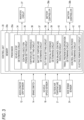
- FIG. 3 is a block diagram illustrating a system for the pack balance control to be performed by the electric circuit 25 in FIG. 2 , and particularly illustrates a control circuit that is included in the processor 20a of the control unit 20 operating to execute the pack balance control.
- the processor 20a includes a vehicle stop determining circuit 34, a control execution period setting circuit 35, a temperature threshold value setting circuit 36, a battery temperature determining circuit 37, a duty ratio setting circuit 38, a potential difference determining circuit 39, a pack balance control executing circuit 40, a travel preparation operation determining circuit 41, a control execution period determining circuit 42, and an electric power supply circuit 43.
- the vehicle stop determining circuit 34 determines whether the electric motorcycle 1 is stopped based on the signals received from the accelerator grip sensor 12, the vehicle speed sensor 18, and the side stand sensor 24. More specifically, when the accelerator grip sensor 12 does not transmit the signal including the start request or the acceleration request to the control unit 20, when the vehicle speed sensor 18 transmits a signal indicating that the rotation speed of the output shaft 17 is zero to the control unit 20, or when the side stand sensor 24 transmits a signal indicating that the side stand 22 contacts the ground to the control unit 20, the vehicle stop determining circuit 34 determines that the electric motorcycle 1 is stopped. On the other hand, when none of the above conditions is satisfied, the vehicle stop determining circuit 34 determines that the electric motorcycle 1 is not stopped.
- the control execution period setting circuit 35 sets a control execution period TO during which the pack balance control is performed. More specifically, when the side stand sensor 24 transmits a signal indicating that the side stand 22 is moved away from the ground to the control unit 20, the electric motorcycle 1 is not parked, and thus the control execution period setting circuit 35 determines that it is necessary to ensure the startability of the electric motorcycle 1, and sets the control execution period TO to a short period. On the other hand, when the side stand sensor 24 transmits the signal indicating that the side stand 22 contacts the ground to the control unit 20, the electric motorcycle 1 is parked, and thus the control execution period setting circuit 35 determines that it is not necessary to ensure the startability of the electric motorcycle 1, and sets the control execution period TO to a long period.
- the temperature threshold value setting circuit 36 sets a temperature threshold value K0 based on the signal including the outside air temperature transmitted from the outside air temperature sensor 21 to the control unit 20. More specifically, the temperature threshold value setting circuit 35 sets the temperature threshold value K0 to a low temperature as the outside air temperature increases, and sets the temperature threshold value K0 to a high temperature as the outside air temperature decreases.
- the battery temperature determining circuit 37 determines whether the temperatures K1, K2 are lower than the temperature threshold value K0 based on the signals including the temperatures K1, K2 of the battery packs 19a, 19b, which are transmitted from the temperature sensors 33a, 33b to the control unit 20 via the battery controllers 30a, 30b.
- the duty ratio setting circuit 38 sets a duty ratio DRO of the pack balance control.
- the duty ratio DRO is the ratio of a time D1 during which the voltage is applied to the gates of the switching elements 29a, 29b and the switching elements 29a, 29b are closed, to the control period C0. More specifically, in order to prevent deterioration due to the temperatures of the battery packs 19a, 19b as the temperatures K1, K2 increase, the duty ratio setting circuit 38 sets the duty ratio DRO to a small value such that the current flowing between the battery pack 19a and the battery pack 19b is reduced.
- the duty ratio setting circuit 38 sets the duty ratio DR0 to a large value such that the current flowing between the battery pack 19a and the battery pack 19b is increased. Further, in order to prevent the electrical interruption between the battery cells 28a, 28b and the electric power path 26 due to the operations of the protection circuits 31a, 31b, the duty ratio setting circuit 38 sets the duty ratio DRO such that the current flowing between the battery pack 19a and the battery pack 19b becomes smaller than the protection current threshold value.
- the potential difference determining circuit 39 calculates the potential difference ⁇ V between the battery pack 19a and the battery pack 19b based on the signals including the potentials V1, V2 of the battery packs 19a, 19b, which are respectively transmitted from the potential measurement circuits 32a, 32b to the control unit 20 via the battery controllers 30a, 30b, and then determines whether the potential difference ⁇ V is larger than a predetermined potential difference threshold value ⁇ V0 or whether the potential difference ⁇ V is smaller than the predetermined potential difference threshold value ⁇ V0.
- the potential difference threshold value ⁇ V0 is set to a potential difference at which the current hardly flows between the battery pack 19a and the battery pack 19b when the electric power is supplied from the battery packs 19a, 19b to the motor 16 via the inverter circuit 27.
- the pack balance control executing circuit 40 performs the pack balance control.
- FIG. 4 is a time chart of the pack balance control performed by the electric circuit 25 in FIG. 2 , and illustrates an example in which a current flows from the battery pack 19a to the battery pack 19b when the potential V1 of the battery pack 19a measured by the potential measurement circuit 32a is higher than the potential V2 of the battery pack 19b measured by the potential measurement circuit 32b.
- the pack balance control starts at a time T1.
- the pack balance control executing circuit 40 transmits a signal including an instruction to close the switching element 29a to the battery controller 30a for every control period C0.
- the battery controller 30a applies the voltage to the gate of the switching element 29a in response to the reception of the signal including the instruction to close the switching element 29a.
- the switching element 29a closes to electrically conduct between the battery cell 28a and the electric power path 26.
- the pack balance control executing circuit 40 transmits a signal including an instruction to open and close the switching element 29b at the duty ratio DR0 to the battery controller 30b for every control period C0.
- the battery controller 30b applies the voltage to the gate of the switching element 29b at the duty ratio DRO in response to the reception of the signal including the instruction to open and close the switching element 29b at the duty ratio DR0. That is, the battery controller 30b applies the voltage to the gate of the switching element 29a during a time D1, and does not apply the voltage to the gate of the switching element 29a during a remaining time D2 with respect to the control period C0.
- the switching element 29b When the voltage is applied to the gate at the duty ratio DR0, the switching element 29b opens and closes to electrically conduct between the battery cell 28b and the electric power path 26 at the duty ratio DR0. That is, the switching element 29b closes to electrically conduct between the battery cell 28b and the electric power path 26 during the time D1, and opens to not electrically conduct between the battery cell 28b and the electric power path 26 during the remaining time D2 with respect to the control period C0.
- the travel preparation operation determining circuit 41 determines whether a preparation operation for causing the electric motorcycle 1 to travel is performed by the driver. More specifically, when the signal including the brake-releasing request is transmitted from the brake switch 14 to the control unit 20, or when a signal including a shift request from the driver is transmitted to the control unit 20, the travel preparation operation determining circuit 41 determines that the preparation operation is performed by the driver. On the other hand, when none of the above conditions is satisfied, the travel preparation operation determining circuit 41 determines that the preparation operation is not performed by the driver.
- the control execution period determining circuit 42 determines whether the control execution period T0 has elapsed.
- the electric power supply circuit 43 transmits a signal including an instruction to close one or both of the switching element 29a and the switching element 29b to the corresponding battery controllers 30a, 30b.
- the battery controllers 30a, 30b apply the voltage to the gates of the switching elements 29a, 29b in response to the reception of the signals including the instructions to close the switching elements 29a, 29b, respectively. Since the voltage is applied to the gates, the switching elements 29a, 29b close to electrically conduct between the battery cells 28a, 28b and the electric power path 26, respectively. Therefore, the electric power is supplied from one or both of the battery pack 19a and the battery pack 19b to the motor 16 via the inverter circuit 27.
- the memory 20b stores a processing program for executing functions of the vehicle stop determining circuit 34, the control execution period setting circuit 35, the temperature threshold value setting circuit 36, the battery temperature determining circuit 37, the duty ratio setting circuit 38, the potential difference determining circuit 39, the pack balance control executing circuit 40, the travel preparation operation determining circuit 41, the control execution period determining circuit 42, and the electric power supply circuit 43, which are mentioned above.
- the processor 20a executes the processing program for executing functions of the vehicle stop determining circuit 34, the control execution period setting circuit 35, the temperature threshold value setting circuit 36, the battery temperature determining circuit 37, the duty ratio setting circuit 38, the potential difference determining circuit 39, the pack balance control executing circuit 40, the travel preparation operation determining circuit 41, the control execution period determining circuit 42, and the electric power supply circuit 43, which is stored in the memory 20b, so as to achieve the functions of the vehicle stop determining circuit 34, the control execution period setting circuit 35, the temperature threshold value setting circuit 36, the battery temperature determining circuit 37, the duty ratio setting circuit 38, the potential difference determining circuit 39, the pack balance control executing circuit 40, the travel preparation operation determining circuit 41, the control execution period determining circuit 42, and the electric power supply circuit 43.
- the processor 20a is an integrated circuit and individually includes the vehicle stop determining circuit 34, the control execution period setting circuit 35, the temperature threshold value setting circuit 36, the battery temperature determining circuit 37, the duty ratio setting circuit 38, the potential difference determining circuit 39, the pack balance control executing circuit 40, the travel preparation operation determining circuit 41, the control execution period determining circuit 42, and the electric power supply circuit 43
- the processor 20a may be a microprocessor that collects the functions of the vehicle stop determining circuit 34, the control execution period setting circuit 35, the temperature threshold value setting circuit 36, the battery temperature determining circuit 37, the duty ratio setting circuit 38, the potential difference determining circuit 39, the pack balance control executing circuit 40, the travel preparation operation determining circuit 41, the control execution period determining circuit 42, and the electric power supply circuit 43.
- FIG. 5 is a flowchart of the pack balance control performed by the electric circuit 25 in FIG. 2 , and particularly illustrates the control process executed by the processor 20a.
- the memory 20b of the control unit 20 stores the program for performing the pack balance control according to the illustrated flowchart.
- step S1 the vehicle stop determining circuit 34 determines whether the electric motorcycle 1 is stopped based on the signals received from the accelerator grip sensor 12, the vehicle speed sensor 18, and the side stand sensor 24 as a first control start condition. If it is determined that the electric motorcycle 1 is not stopped (NO in step S1), the control process ends so that the pack balance control is not performed, and if it is determined that the electric motorcycle 1 is stopped (YES in step S1), the control process proceeds to the next step S2.
- step S2 the control execution period setting circuit 35 sets the control execution period T0 during which the pack balance control is performed.
- step S3 the temperature threshold value setting circuit 36 sets the temperature threshold value K0.
- step S4 the battery temperature determining circuit 37 determines whether the temperatures K1, K2 of the battery packs 19a, 19b are lower than the temperature threshold value K0 based on the signals including the temperatures K1, K2 of the battery packs 19a, 19b, which are respectively transmitted from the temperature sensors 33a, 33b to the control unit 20 via the battery controllers 30a, 30b, as a second control start condition. If it is determined that the temperature of at least one battery pack is higher than the temperature threshold value K0 (NO in step S4), in order to prevent the deterioration due to the temperatures of the battery packs 19a, 19b, the control process ends so that the pack balance control is not performed. On the other hand, if it is determined that the temperatures K1, K2 of the battery packs 19a, 19b are lower than the temperature threshold value K0 (YES in step S4), the control process proceeds to the next step S5.
- step S5 the duty ratio setting circuit 38 sets the duty ratio DRO of the pack balance control.
- step S6 the potential difference determining circuit 39 calculates the potential difference ⁇ V between the battery pack 19a and the battery pack 19b based on the signals including the potentials V1, V2 of the battery packs 19a, 19b, which are respectively transmitted from the potential measurement circuits 32a, 32b to the control unit 20 via the battery controllers 30a, 30b, and then determines whether the potential difference ⁇ V is larger than the predetermined potential difference threshold value ⁇ V0 as a third control start condition.
- step S6 If it is determined that the potential difference ⁇ V is smaller than the potential difference threshold value ⁇ V0 (NO in step S6), since it is not necessary to perform the pack balance control, the control process ends, and if it is determined that the potential difference ⁇ V is larger than the potential difference threshold value ⁇ V0 (YES in step S6), the control process proceeds to the next step S7.
- step S7 the pack balance control executing circuit 40 performs the pack balance control described above during the control period C0. Thereafter, when the control period C0 has elapsed, the control process proceeds to the next step S8.
- the pack balance control is interrupted, and the control process proceeds to the next step S8.
- step S8 of FIG. 5 the travel preparation operation determining circuit 41 determines whether the preparation operation for causing the electric motorcycle 1 to travel is performed by the driver as a first control end condition. If it is determined that the preparation operation is performed by the driver (YES in step S8), the control process ends, and if it is determined that the preparation operation is not performed by the driver (NO in step S8), the control process proceeds to the next step S9.
- step S9 the control execution period determining circuit 42 determines whether the control execution period TO has elapsed as a second control end condition. If it is determined that the control execution period T0 has elapsed (YES in step S9), the control process ends, and if it is determined that the control execution period TO has not elapsed (NO in step S9), the control process returns to step S4.
- control process repeats steps S4 to S9 every control period C0.
- FIG. 6 is a graph illustrating transition of the potentials V1, V2 of the battery packs 19a, 19b due to the pack balance control in FIG. 4 .
- the potential V1 of the battery pack 19a is higher than the potential V2 of the battery pack 19b.
- the pack balance control is performed, and thus the current flows from the battery pack 19a to the battery pack 19b.
- the pack balance control is performed as the intermittent charging and discharging operation at the duty ratio DR0, an amount of electricity per unit time flowing from the battery pack 19a to the battery pack 19b is suppressed such that the current flowing between the battery pack 19a and the battery pack 19b does not become an overcurrent, and the potential difference ⁇ V between the battery pack 19a and the battery pack 19b gradually decreases.
- the control unit 20 transmits signals including instructions to open the switching elements 29a, 29b to the battery controllers 30a, 30b, respectively.
- the battery controllers 30a, 30b do not apply the voltage to the gates of the switching elements 29a, 29b in response to the reception of the signals including the instructions to open the switching elements 29a, 29b, respectively. Since no voltage is applied to the gates, the switching elements 29a, 29b open to not electrically conduct between the battery cells 28a, 28b and the electric power path 26, respectively. Accordingly, the charging and discharging operation is not performed between the battery pack 19a and the battery pack 19b.
- the above example of the pack balance control shows the case where the current flows from the battery pack 19a to the battery pack 19b, and the pack balance control is also performed in a case where the current flows from the battery pack 19b to the battery pack 19a.
- the pack balance control is performed with reference to the flow including steps S1 to S9 described above.
- the electric motorcycle 1 has a mode in which the electric power is supplied from the two battery packs 19a, 19b to the motor 16.
- FIG. 7 is a flowchart of the electric power supply performed by the electric circuit 25 in FIG. 2 , and particularly illustrates the control process performed by the processor 20a of the control unit 20.
- the memory 20b of the control unit 20 stores a program for supplying the electric power to the motor 16 with reference to the illustrated flowchart.
- step S11 the potential difference determining circuit 39 calculates the potential difference ⁇ V between the battery pack 19a and the battery pack 19b based on the signals including the potentials V1, V2 of the battery packs 19a, 19b, which are respectively transmitted from the potential measurement circuits 32a, 32b to the control unit 20 via the battery controllers 30a, 30b, and then determines whether the potential difference ⁇ V is smaller than the predetermined potential difference threshold value ⁇ V0.
- step S12 the electric power supply circuit 43 transmits signals including instructions to close the switching element 29a and the switching element 29b to the battery controller 30a and the battery controller 30b, respectively.
- the battery controllers 30a, 30b apply the voltage to the gates of the switching elements 29a, 29b in response to the reception of the signals including the instructions to close the switching elements 29a, 29b, respectively. Since the voltage is applied to the gates, the switching elements 29a, 29b close to electrically conduct between the battery cells 28a, 28b and the electric power path 26, respectively. Therefore, the electric power is supplied from both the battery pack 19a and the battery pack 19b to the motor 16 via the inverter circuit 27.
- the motor 16 receives the electric power supply from both the battery pack 19a and the battery pack 19b and outputs a large driving force.
- step S11 If it is determined in step S11 that the potential difference ⁇ V is larger than the potential difference threshold value ⁇ V0 (NO in step S11), the control process proceeds to step S13.
- step S13 in order to suppress the flow of the current between the battery pack 19a and the battery pack 19b by the electric power supply circuit 43, a signal including an instruction to close the switching element of one battery pack having a high potential among the battery packs 19a, 19b is transmitted to the corresponding one of the battery controller 30a and the battery controller 30b.
- the battery controllers 30a, 30b apply the voltage to the gates of the switching elements 29a, 29b in response to the reception of the signals including the instructions to close the switching elements 29a, 29b, respectively. Since the voltage is applied to the gates, the switching elements 29a, 29b close to electrically conduct between the battery cells 28a, 28b and the electric power path 26, respectively. Therefore, the electric power is supplied from one of the battery pack 19a and the battery pack 19b to the motor 16 via the inverter circuit 27.
- the motor 16 receives the electric power supply from the single battery pack and outputs the driving force.
- step S14 the vehicle stop determining circuit 34 determines whether the electric motorcycle 1 is stopped based on information included in the signals received from the accelerator grip sensor 12, the vehicle speed sensor 18, and the side stand sensor 24 as in step S1 of the flowchart in FIG. 5 .
- step S14 if it is determined that the electric motorcycle 1 is not stopped (NO in step S14), the control process returns to step S11, and if it is determined that the electric motorcycle 1 is stopped (YES in step S14), the control process ends.
- control unit 20 performs a control process for charging the two battery packs 19a, 19b by using regenerative power of the motor 16.
- the control unit 20 transmits a signal including an instruction to close the switching element 29a or the switching element 29b to the battery controller 30a or the battery controller 30b so as to charge one low-potential battery pack having a low potential among the two battery packs 19a, 19b by using the regenerative power.
- the potential difference ⁇ V between the high-potential battery pack and the low-potential battery pack is reduced by preferentially charging the low-potential battery pack by using the regenerative power of the motor 16.
- the electric motorcycle 1 configured as described above has the following features.
- the electric motorcycle 1 according to the present embodiment includes:
- the present embodiment due to the intermittent charging and discharging operation, it is possible to reduce the potential difference ⁇ V between the two battery packs 19a, 19b while suppressing the amount of electricity per unit time flowing between the battery packs 19a, 19b. Accordingly, the current flowing between the two battery packs 19a, 19b is prevented from becoming an overcurrent, and the electric power path 26, the two battery packs 19a, 19b, and other electrical components are protected. In addition, by reducing the potential difference ⁇ V between the two battery packs 19a, 19b, the current is suppressed from flowing between the two battery packs 19a, 19b when the electric motorcycle 1 travels.
- the electric motorcycle 1 includes the accelerator grip sensor 12, the vehicle speed sensor 18, and the side stand sensor 24 which detect information indicating that the electric motorcycle 1 is stopped and transmit the information to the control unit 20, the control start condition is the determination that the electric motorcycle 1 is stopped, which is performed by the control unit 20 based on the information.
- the pack balance control when it is determined that the electric motorcycle 1 is stopped by using the accelerator grip sensor 12, the vehicle speed sensor 18, and the side stand sensor 24, the pack balance control is performed. Therefore, when the electric motorcycle l travels, the pack balance control is not performed, and thus the potential difference ⁇ V between the two battery packs 19a, 19b can be reduced while suppressing an influence on traveling comfort.
- the two battery packs 19a, 19b include the temperature sensors 33a, 33b that detect the temperatures K1, K2 of the two battery packs 19a, 19b and transmit the temperatures K1, K2 to the control unit 20, respectively, and the control start condition is the determination that the temperatures K1, K2 are lower than the predetermined temperature threshold value K0, which is performed by the control unit 20.
- the pack balance control is performed. Therefore, the respective temperatures K1, K2 of the two battery packs 19a, 19b are less likely to become high, and thus the deterioration due to the temperature of the two battery packs 19a, 19b can be easily prevented.
- the electric motorcycle 1 further includes the outside air temperature sensor 21 that detects the outside air temperature and transmits the outside air temperature to the control unit 20, the control unit 20 sets the temperature threshold value K0 to decrease as the outside air temperature increases.
- the temperature threshold value K0 when the outside air temperature is high, the temperature threshold value K0 is set to a low temperature. Therefore, the pack balance control is difficult to be performed, and thus the deterioration due to the temperature of the two battery packs 19a, 19b can be easily prevented.
- the temperature threshold value K0 when the outside air temperature is low, the temperature threshold value K0 is set to a high temperature. Therefore, the pack balance control is easy to be performed, and thus warm-up of the two battery packs 19a, 19b can be promoted.
- control unit 20 sets the duty ratio DRO of the intermittent charging and discharging operation to decrease as the temperatures K1, K2 increase.
- the intermittent charging and discharging operation is performed at the small duty ratio DR0, and thus the deterioration due to the temperature of the two battery packs 19a, 19b is easily prevented.
- the temperatures K1, K2 are low, the intermittent charging and discharging operation is performed at the large duty ratio DR0, and thus the potential difference ⁇ V between the two battery packs 19a, 19b is easily reduced.
- the electric motorcycle 1 includes the protection circuits 31a, 31b that measure the current flowing through the two battery packs 19a, 19b and stop the electric power supply of the two battery packs 19a, 19b when the current is larger than the predetermined protection current threshold value, respectively, and the control unit 20 sets the duty ratio DRO of the intermittent charging and discharging operation such that the current is smaller than the protection current threshold value.
- the duty ratio DRO of the intermittent charging and discharging operation such that the current flowing through the two battery packs 19a, 19b is smaller than the protection current threshold value, it is possible to reduce the potential difference ⁇ V between the two battery packs 19a, 19b while preventing the operations of the protection circuits 31a, 31b that stop the electric power supply of the battery packs 19a, 19b in order to prevent the current flowing between the two battery packs 19a, 19b from becoming an overcurrent and prevent the temperatures of the two battery packs 19a, 19b from increasing excessively.
- the electric motorcycle 1 includes the potential measurement circuits 32a, 32b that measure the potentials V1, V2 of the two battery packs 19a, 19b, respectively, and the control unit 20 calculates the potential difference ⁇ V between the two battery packs 19a, 19b based on the respective potentials V1, V2 of the two battery packs 19a, 19b measured by the potential measurement circuits 32a, 32b, and supplies the electric power from the two battery packs 19a, 19b to the motor 16 when the potential difference ⁇ V is equal to or less than the predetermined potential difference threshold value ⁇ V0.
- the present embodiment by supplying the electric power from the two battery packs 19a, 19b having the small potential difference ⁇ V to the motor 16, it is possible to suppress the current from flowing between the two battery packs 19a, 19b and to improve traveling performance of the electric motorcycle 1.
- control start condition is the determination that the potential difference ⁇ V between the two battery packs 19a, 19b is larger than the potential difference threshold value ⁇ V0, which is performed by the control unit 20.
- the pack balance control is performed, and thus the potential difference ⁇ V between the two battery packs 19a, 19b can be reduced. Further, when the potential difference ⁇ V between the two battery packs 19a, 19b is small, the current flowing between the two battery packs 19a, 19b does not become an overcurrent, and thus the pack balance control is not performed.
- control unit 20 controls the switching elements 29a, 29b such that the current flows from the high-potential battery pack having a high potential to the low-potential battery pack having a low potential among the two battery packs 19a, 19b, and the potential difference ⁇ V between the high-potential battery pack and the low-potential battery pack is reduced.
- the potential difference ⁇ V between the high-potential battery pack and the low-potential battery pack can be reduced.
- control unit 20 controls the switching elements 29a, 29b such that the low-potential battery pack having a low potential among the two battery packs 19a, 19b is charged by using the regenerative power.
- the potential difference ⁇ V between the high-potential battery pack and the low-potential battery pack can be reduced by preferentially charging the low-potential battery pack by using the regenerative power of the motor 16.
- the control unit 20 stops the pack balance control.
- the pack balance control is stopped, and thus the startability of the electric motorcycle 1 can be secured.
- control unit 20 sets the control execution period TO for executing the pack balance control in accordance with a state of the electric motorcycle 1.
- the control unit 20 determines that it is necessary to ensure the startability of the electric motorcycle 1, and sets the control execution period TO of the pack balance control to a short period.
- the control unit 20 determines that it is not necessary to ensure the startability of the electric motorcycle 1, and sets the control execution period T0 of the pack balance control to a long period.
- the two battery packs 19a, 19b may be connected in parallel.
- the electric motorcycle 1 can travel as long as at least one battery pack is electrically connected to the motor 16 via the electric power path 26. Further, although the potential difference ⁇ V is likely to occur between the two battery packs 19a, 19b, the potential difference ⁇ V can be reduced by the pack balance control.
- the present embodiment provides a control method for the electric motorcycle 1, the control method for the electric motorcycle 1 includes the pack balance control that causes the switching elements 29a, 29b for switching the electrical disconnection and connection of the electric power path 26 to repeatedly open and close so as to perform the intermittent charging and discharging operation between the two battery packs 19a, 19b for supplying the electric power to the motor 16 causing the electric motorcycle l to travel, and reduces the potential difference ⁇ V between the two battery packs 19a, 19b, and the electric power path 26 electrically connects the motor 16 and the two battery packs 19a, 19b.
- the control method for the electric motorcycle 1 includes the pack balance control that causes the switching elements 29a, 29b for switching the electrical disconnection and connection of the electric power path 26 to repeatedly open and close so as to perform the intermittent charging and discharging operation between the two battery packs 19a, 19b for supplying the electric power to the motor 16 causing the electric motorcycle l to travel, and reduces the potential difference ⁇ V between the two battery packs 19a, 19b, and the electric power path 26 electrical
- the control method of the present embodiment due to the intermittent charging and discharging operation, it is possible to reduce the potential difference ⁇ V between the two battery packs 19a, 19b while suppressing the amount of electricity per unit time flowing between the two battery packs 19a, 19b. Accordingly, the current flowing between the two battery packs 19a, 19b is prevented from becoming an overcurrent, and the electric power path 26, the two battery packs 19a, 19b, and other electrical components are protected. In addition, by reducing the potential difference ⁇ V between the two battery packs 19a, 19b, the current is suppressed from flowing between the two battery packs 19a, 19b when the electric motorcycle 1 travels.
- the electric vehicle 1 is an electric motorcycle, and may be an electric automobile.
- the two battery packs 19a, 19b are connected in parallel, and may be connected in series.
- the protection circuits 31a, 31b respectively include the current measurement circuits, and may alternatively include temperature measurement circuits that measure the temperatures of the battery cells 28a, 28b corresponding to the currents flowing through the battery cells 28a, 28b, respectively.
- the measured temperatures that is, current equivalent values are larger than a predetermined protection current equivalent threshold value
- the protection current equivalent threshold value is determined based on the temperatures of the battery cells 28a, 28b when the allowable maximum current of the battery cells 28a, 28b flows.
- the two battery packs 19a, 19b respectively include the temperature sensors 33a, 33b, and may alternatively include current measurement circuits that measure the currents of the battery packs 19a, 19b corresponding to the temperatures K1, K2 of the battery packs 19a, 19b, respectively.
- the current measurement circuits transmit signals including the measured currents, that is, temperature equivalent values to the battery controllers 30a, 30b, respectively.
- the temperature equivalent values are not limited to the currents, and may be values that correlate with the temperatures K1, K2 of the battery packs 19a, 19b and can indirectly indicate the temperatures K1, K2 of the battery packs 19a, 19b, for example, the number of times of charging and discharging in a predetermined time, charging rates of the battery packs 19a, 19b, the outside air temperature, coolant temperatures of the battery packs 19a, 19b, or the like.
- the temperature equivalent values may be corrected according to a past travel state of the electric motorcycle 1.
- the temperature threshold value K0 is set by the temperature threshold value setting circuit 36 in accordance with the outside air temperature, and may be a fixed value.
- the duty ratio DRO is set by the duty ratio setting circuit 38 in accordance with the temperatures K1, K2 of the battery packs 19a, 19b, and may be a fixed value.
- an electric vehicle includes: a motor configured to cause the electric vehicle to travel; a plurality of battery packs configured to supply electric power to the motor; an electric power path electrically connecting the motor and the plurality of battery packs; a switching element configured to electrically switch disconnection and connection of the electric power path; and a controller configured to control the switching element.
- the controller performs a pack balance control that causes, when at least one of predetermined control start conditions is satisfied, the switching element to repeatedly open and close to perform an intermittent charging and discharging operation between the plurality of battery packs, and reduces a potential difference between the plurality of battery packs.
- the electric vehicle in the first aspect further includes: a vehicle stop sensor configured to detect information indicating that the electric vehicle is stopped and transmit the information to the controller.
- the at least one of the control start conditions includes a determination performed by the controller that the electric vehicle is stopped based on the information.
- each of the plurality of battery packs includes a temperature equivalent value sensor that detects a temperature equivalent value corresponding to a temperature for each of the plurality of battery packs and transmits the temperature equivalent value to the controller, and the at least one of the control start conditions includes a determination performed by the controller that the temperature equivalent value is smaller than a predetermined temperature equivalent threshold value.
- the electric vehicle further includes: an outside air temperature sensor configured to detect an outside air temperature and transmit the outside air temperature to the controller.
- the controller sets the temperature equivalent threshold value to decrease as the outside air temperature increases.
- the controller set a duty ratio of the intermittent charging and discharging operation to decrease as the temperature equivalent value increases.
- the electric vehicle in any one of the first to fifth aspects further includes a protection circuit configured to measure a current equivalent value corresponding to a current flowing through the plurality of battery packs, and stop supplying the electric power to the plurality of battery packs when the current equivalent value is larger than a predetermined protection current equivalent threshold value.
- the controller sets a duty ratio of the intermittent charging and discharging operation such that the current equivalent value is smaller than the protection current equivalent threshold value.
- the electric vehicle in any one of the first to sixth aspects further includes a potential measurement circuit configured to measure a potential for each of the plurality of battery packs.
- the controller calculates the potential difference between the plurality of battery packs based on the potentials of the plurality of battery packs measured by the potential measurement circuit, and supplies the electric power from the plurality of battery packs to the motor when the potential difference is equal to or less than a predetermined potential difference threshold value.
- the at least one of the control start conditions includes a determination performed by the controller that the potential difference between the plurality of battery packs is larger than the potential difference threshold value.
- the controller when performing the pack balance control, controls the switching element such that a current flows from a high-potential battery pack having a high potential to a low-potential battery pack having a low potential among the plurality of battery packs, and thereby reducing a potential difference between the high-potential battery pack and the low-potential battery pack.
- the controller controls the switching element such that a low-potential battery pack having a lower potential is charged by the regenerative power among the plurality of battery packs.
- the controller when determining that a preparation operation for causing the electric vehicle to travel is performed by a driver, the controller stops the pack balance control.
- the controller sets a control execution period for executing the pack balance control in accordance with a state of the electric vehicle.
- the plurality of battery packs are connected in parallel.
- a control method for an electric vehicle that includes a motor configured to cause the electric vehicle to travel, a plurality of battery packs configured to supply electric power to the motor, an electric power path electrically connecting the motor and the plurality of battery packs, a switching element configured to electrically switch disconnection and connection of the electric power path, includes: a pack balance control that causes the switching element to repeatedly open and close and thereby performing an intermittent charging and discharging operation between the plurality of battery packs, and reduces a potential difference between the plurality of battery packs.
- a program causes a computer to execute the control method for the electric vehicle in the fourteenth aspect.
- a non-transitory computer readable medium stores the program in the fifteenth aspect.
Landscapes
- Engineering & Computer Science (AREA)
- Mechanical Engineering (AREA)
- Power Engineering (AREA)
- Transportation (AREA)
- Life Sciences & Earth Sciences (AREA)
- Sustainable Development (AREA)
- Sustainable Energy (AREA)
- Chemical & Material Sciences (AREA)
- Combustion & Propulsion (AREA)
- Manufacturing & Machinery (AREA)
- Chemical Kinetics & Catalysis (AREA)
- Electrochemistry (AREA)
- General Chemical & Material Sciences (AREA)
- Electric Propulsion And Braking For Vehicles (AREA)
- Charge And Discharge Circuits For Batteries Or The Like (AREA)
Abstract
There are provided an electric vehicle and a control method thereof, the electric vehicle including: a motor configured to cause the electric vehicle to travel; a plurality of battery packs configured to supply electric power to the motor; an electric power path electrically connecting the motor and the plurality of battery packs; a switching element configured to electrically switch disconnection and connection of the electric power path; and a controller configured to control the switching element. The controller performs a pack balance control that causes, when at least one of predetermined control start conditions is satisfied, the switching element to repeatedly open and close to perform an intermittent charging and discharging operation between the plurality of battery packs, and reduces a potential difference between the plurality of battery packs.
Description
- The present disclosure relates to an electric vehicle and a control method for the electric vehicle.
-
WO2015/068753A1 discloses an electric vehicle including a plurality of battery packs. - According to
WO2015/068753A1 , it is possible to drive a motor by using electric power supplied from the plurality of battery packs to cause the electric vehicle to travel. - Each of the plurality of battery packs is detachable, and is detached from the electric vehicle and charged by using a charger.
- However, when the motor is driven by using the electric power supplied from the plurality of battery packs, a current flows between the plurality of battery packs and makes it difficult to drive the motor, and the service life of each of the battery packs is reduced in some cases.
- In particular, when the current flowing between the plurality of battery packs is an overcurrent, the plurality of battery packs, an electric power path electrically connecting the plurality of battery packs, and other electrical components may be electrically damaged.
- Accordingly, an object of the present disclosure is to provide an electric vehicle in which a current flowing between a plurality of battery packs is prevented from being an overcurrent.
- According to an illustrative aspect of the present disclosure, an electric vehicle includes: a motor configured to cause the electric vehicle to travel; a plurality of battery packs configured to supply electric power to the motor; an electric power path electrically connecting the motor and the plurality of battery packs; a switching element configured to electrically switch disconnection and connection of the electric power path; and a controller configured to control the switching element. The controller performs a pack balance control that causes, when at least one of predetermined control start conditions is satisfied, the switching element to repeatedly open and close to perform an intermittent charging and discharging operation between the plurality of battery packs, and reduces a potential difference between the plurality of battery packs.
- According to the present disclosure, due to the intermittent charging and discharging operation, it is possible to reduce the potential difference between the plurality of battery packs while suppressing an amount of electricity flowing between the plurality of battery packs per unit time. Accordingly, the current flowing between the plurality of battery packs is prevented from being an overcurrent, and the electric power path, the plurality of battery packs, and other electrical components are protected. In addition, by reducing the potential difference between the plurality of battery packs, the current is suppressed from flowing between the plurality of battery packs when the electric vehicle travels.
- According to another illustrative aspect of the present disclosure, a control method for an electric vehicle that includes a motor configured to cause the electric vehicle to travel, a plurality of battery packs configured to supply electric power to the motor, an electric power path electrically connecting the motor and the plurality of battery packs, a switching element configured to electrically switch disconnection and connection of the electric power path, includes: a pack balance control that causes the switching element to repeatedly open and close and thereby performing an intermittent charging and discharging operation between the plurality of battery packs, and reduces a potential difference between the plurality of battery packs.
- According to the present disclosure, due to the intermittent charging and discharging operation, it is possible to reduce the potential difference between the plurality of battery packs while suppressing an amount of electricity flowing between the plurality of battery packs per unit time. Accordingly, the current flowing between the plurality of battery packs is prevented from being an overcurrent, and the electric power path, the plurality of battery packs, and other electrical components are protected. In addition, by reducing the potential difference between the plurality of battery packs, the current is suppressed from flowing between the plurality of battery packs when the electric vehicle travels.
- Therefore, according to the electric vehicle of the present disclosure, it is possible to reduce the potential difference between the plurality of battery packs while preventing the current flowing between the plurality of battery packs from being an overcurrent.
-
-
FIG. 1 is a side view of an electric vehicle according to an embodiment of the present disclosure; -
FIG. 2 is a circuit diagram of the electric vehicle inFIG. 1 ; -
FIG. 3 is a block diagram illustrating a system for a pack balance control performed by the circuit inFIG. 2 ; -
FIG. 4 is a time chart of the pack balance control performed by the circuit inFIG. 2 ; -
FIG. 5 is a flowchart of the pack balance control performed by the circuit inFIG. 2 ; -
FIG. 6 is a graph illustrating a potential transition of battery packs by the pack balance control inFIG. 4 ; and -
FIG. 7 is a flowchart of electric power supply performed by the circuit inFIG. 2 . - Hereinafter, an embodiment of the present disclosure will be described with reference to the accompanying drawings.
-
FIG. 1 is a side view of an electric vehicle (hereinafter referred to as an "electric motorcycle") 1 according to the embodiment of the present disclosure. Directions such as a front direction, a rear direction, a right direction, and a left direction in the present embodiment are directions viewed by a driver riding on theelectric motorcycle 1. - The
electric motorcycle 1 includes aframe 2 that is a main body of theelectric motorcycle 1, a front wheel 3 disposed in front of theframe 2, and a rear wheel 4 disposed behind theframe 2. - The front wheel 3 is rotatably supported by a lower portion of a
front fork 5 extending in an up-down direction. Thefront fork 5 is supported by asteering shaft 8 via anupper bracket 7 provided at an upper end portion of thefront fork 5 and alower bracket 6 provided below theupper bracket 7. Thesteering shaft 8 is pivotably supported by ahead pipe 9 attached to theframe 2. - A
handlebar 10 extending in a left-right direction is attached to theupper bracket 7. The front wheel 3 is steered around thesteering shaft 8 as a rotation shaft due to a swing operation of thehandlebar 10 toward the left-right direction performed by the driver. - An
accelerator grip 11 is rotatably attached to thehandlebar 10 on both sides. When starting or accelerating theelectric motorcycle 1, the driver issues a start request or an acceleration request by rotating theaccelerator grip 11. Theaccelerator grip 11 includes anaccelerator grip sensor 12 electrically connected to acontrol unit 20 to be described later. Theaccelerator grip sensor 12 transmits a signal including the start request or the acceleration request described above to thecontrol unit 20 by detecting the rotation of theaccelerator grip 11. - Further, a
brake lever 13 is operably attached to thehandlebar 10 on both sides. When stopping theelectric motorcycle 1, the driver operates thebrake lever 13 to issue a braking request, and when starting theelectric motorcycle 1, the driver releases thebrake lever 13 to issue a brake-releasing request. Thebrake lever 13 includes abrake switch 14 electrically connected to thecontrol unit 20 to be described later. Thebrake switch 14 transmits a signal including the braking request or the brake-releasing request described above to thecontrol unit 20 by detecting an operation on thebrake lever 13. - A
drive system 15 for driving the rear wheel 4 is disposed inside theframe 2 in order to cause theelectric motorcycle 1 to travel. Thedrive system 15 includes amotor 16 that generates a driving force by being supplied with electric power, and an output shaft 17 that outputs the driving force of themotor 16 toward the rear wheel 4. Further, avehicle speed sensor 18 electrically connected to thecontrol unit 20 to be described later is disposed inside theframe 2. Thevehicle speed sensor 18 detects a rotation speed of the output shaft 17 and transmits a signal including the rotation speed to thecontrol unit 20. - Two chargeable and
dischargeable battery packs motor 16 and supply electric power to themotor 16, are disposed inside theframe 2. Each of the twobattery packs frame 2. In the present embodiment, the twobattery packs - The
control unit 20 electrically connected to electrical components such as theaccelerator grip sensor 12, thebrake switch 14, themotor 16, thevehicle speed sensor 18, and thebattery packs frame 2. Thecontrol unit 20 is an integrated circuit that controls thedrive system 15, particularly themotor 16, and controls the twobattery packs accelerator grip sensor 12, thevehicle speed sensor 18, and the like, and thecontrol unit 20 includes aprocessor 20a that performs a control process and amemory 20b that stores a control program. - An outside
air temperature sensor 21 is attached inside theframe 2. The outsideair temperature sensor 21 is electrically connected to thecontrol unit 20, and transmits a signal including an outside air temperature to thecontrol unit 20. - A rod-
shaped side stand 22 is attached to a side surface of theframe 2. Theside stand 22 has aside stand shaft 23 extending in the left-right direction at one end thereof. Theside stand shaft 23 is connected to theframe 2 and serves as a rotation shaft of theside stand 22. For example, when the driver starts theelectric motorcycle 1, the driver rotates the side stand 22 upward by using a foot so that theside stand 22 is rotated upward around theside stand shaft 23 to move away from the ground, on the other hand, when the driver parks theelectric vehicle 1, the driver lowers the side stand 22 by using the foot so that theside stand 22 is rotated downward around theside stand shaft 23 to contact the ground. In addition, theside stand 22 includes aside stand sensor 24 that is electrically connected to thecontrol unit 20 and transmits a signal including a state of theside stand 22 described above to thecontrol unit 20. -
FIG. 2 is a circuit diagram of theelectric motorcycle 1 inFIG. 1 , and particularly illustrates anelectric circuit 25 that electrically connects themotor 16, the twobattery packs control unit 20. - The
electric circuit 25 includes anelectric power path 26 that connects the twobattery packs battery packs motor 16 via aninverter circuit 27 to be described later in order to supply the electric power from the twobattery packs motor 16. - The
electric circuit 25 also includes theinverter circuit 27 that adjusts the frequency of AC power supplied to themotor 16. Theinverter circuit 27 includes switchingelements 27a to 27f mutually connected in a three-phase bridge manner. Each of theswitching elements 27a to 27f is a MOSFET, and a gate thereof is electrically connected to thecontrol unit 20. - Each of the
switching elements 27a to 27f has a characteristic of closing to electrically conduct between a source and a drain when a voltage is applied to the gate, and opening to not electrically conduct between the source and the drain when no voltage is applied to the gate. Therefore, thecontrol unit 20 adjusts the frequency of the AC power supplied to themotor 16 by controlling the voltage applied to the gates of theswitching elements 27a to 27f. - In the present embodiment, the two
battery packs battery cells motor 16 via theelectric power path 26 and theinverter circuit 27, switchingelements battery cells electric power path 26,battery controllers switching elements protection circuits - In
FIG. 2 , each of thebattery cells battery cells - The
switching elements battery cells electric power path 26, and gates thereof are electrically connected to thebattery controllers - Each of the
switching elements battery cells electric power path 26 when the voltage is applied to the gates of theswitching elements electric power path 26 when no voltage is applied to the gates of theswitching elements - The
battery controllers switching elements switching elements battery controllers switching elements battery cells electric power path 26 are controlled, and the supply of the electric power to themotor 16 from the twobattery packs battery packs - The
protection circuits battery cells battery cells electric power path 26, respectively. When the measured currents are larger than a predetermined protection current threshold value, theprotection circuits battery cells electric power path 26, thereby preventing an overcurrent from flowing through thebattery cells battery cells - In the present embodiment, the two
battery packs potential measurement circuits temperature sensors - The
potential measurement circuits battery cells battery controllers battery controllers - The
temperature sensors battery controllers battery controllers - The
battery controllers control unit 20. Thecontrol unit 20 controls thebattery controllers switching elements battery controllers - The
memory 20b of thecontrol unit 20 stores a program for causing thebattery controllers switching elements - The pack balance control is a control that causes, when a predetermined control start condition to be described later is satisfied, the
switching elements battery packs battery packs - Functions achieved by the components described in the present description may be implemented in a circuitry or a processing circuitry including a general-purpose processor, a specific-purpose processor, an integrated circuit, application specific integrated circuits (ASICs), a central processing unit (CPU), a typical circuit in the related art, and/or a combination thereof, the circuitry or the processing circuitry is programmed to achieve the described functions. The
processor 20a includes a transistor and other circuits, and is regarded as the circuitry or the processing circuitry. Theprocessor 20a may be a programmed processor that executes the program stored in thememory 20b. In the present description, the circuitry, the unit, and the means are hardware programmed to achieve the functions described above or hardware for executing the functions described above. The hardware may be any hardware disclosed in the present description, or any hardware that is programmed to achieve the functions described above, or is known as hardware for executing the functions described above. When the hardware is a processor regarded as a circuitry type processor, the circuitry, the means, or the unit is a combination of hardware and software used to configure the hardware and/or a processor. -
FIG. 3 is a block diagram illustrating a system for the pack balance control to be performed by theelectric circuit 25 inFIG. 2 , and particularly illustrates a control circuit that is included in theprocessor 20a of thecontrol unit 20 operating to execute the pack balance control. - The
processor 20a includes a vehiclestop determining circuit 34, a control executionperiod setting circuit 35, a temperature thresholdvalue setting circuit 36, a batterytemperature determining circuit 37, a dutyratio setting circuit 38, a potentialdifference determining circuit 39, a pack balancecontrol executing circuit 40, a travel preparationoperation determining circuit 41, a control executionperiod determining circuit 42, and an electricpower supply circuit 43. - The vehicle stop determining
circuit 34 determines whether theelectric motorcycle 1 is stopped based on the signals received from theaccelerator grip sensor 12, thevehicle speed sensor 18, and the side standsensor 24. More specifically, when theaccelerator grip sensor 12 does not transmit the signal including the start request or the acceleration request to thecontrol unit 20, when thevehicle speed sensor 18 transmits a signal indicating that the rotation speed of the output shaft 17 is zero to thecontrol unit 20, or when the side standsensor 24 transmits a signal indicating that the side stand 22 contacts the ground to thecontrol unit 20, the vehicle stop determiningcircuit 34 determines that theelectric motorcycle 1 is stopped. On the other hand, when none of the above conditions is satisfied, the vehicle stop determiningcircuit 34 determines that theelectric motorcycle 1 is not stopped. - The control execution
period setting circuit 35 sets a control execution period TO during which the pack balance control is performed. More specifically, when the side standsensor 24 transmits a signal indicating that the side stand 22 is moved away from the ground to thecontrol unit 20, theelectric motorcycle 1 is not parked, and thus the control executionperiod setting circuit 35 determines that it is necessary to ensure the startability of theelectric motorcycle 1, and sets the control execution period TO to a short period. On the other hand, when the side standsensor 24 transmits the signal indicating that the side stand 22 contacts the ground to thecontrol unit 20, theelectric motorcycle 1 is parked, and thus the control executionperiod setting circuit 35 determines that it is not necessary to ensure the startability of theelectric motorcycle 1, and sets the control execution period TO to a long period. - The temperature threshold
value setting circuit 36 sets a temperature threshold value K0 based on the signal including the outside air temperature transmitted from the outsideair temperature sensor 21 to thecontrol unit 20. More specifically, the temperature thresholdvalue setting circuit 35 sets the temperature threshold value K0 to a low temperature as the outside air temperature increases, and sets the temperature threshold value K0 to a high temperature as the outside air temperature decreases. - The battery
temperature determining circuit 37 determines whether the temperatures K1, K2 are lower than the temperature threshold value K0 based on the signals including the temperatures K1, K2 of the battery packs 19a, 19b, which are transmitted from thetemperature sensors control unit 20 via thebattery controllers - The duty
ratio setting circuit 38 sets a duty ratio DRO of the pack balance control. The duty ratio DRO is the ratio of a time D1 during which the voltage is applied to the gates of theswitching elements switching elements ratio setting circuit 38 sets the duty ratio DRO to a small value such that the current flowing between thebattery pack 19a and thebattery pack 19b is reduced. On the other hand, in order to promote the charging and discharging of the battery packs 19a, 19b as the temperatures K1, K2 decrease, the dutyratio setting circuit 38 sets the duty ratio DR0 to a large value such that the current flowing between thebattery pack 19a and thebattery pack 19b is increased. Further, in order to prevent the electrical interruption between thebattery cells electric power path 26 due to the operations of theprotection circuits ratio setting circuit 38 sets the duty ratio DRO such that the current flowing between thebattery pack 19a and thebattery pack 19b becomes smaller than the protection current threshold value. - The potential
difference determining circuit 39 calculates the potential difference ΔV between thebattery pack 19a and thebattery pack 19b based on the signals including the potentials V1, V2 of the battery packs 19a, 19b, which are respectively transmitted from thepotential measurement circuits control unit 20 via thebattery controllers battery pack 19a and thebattery pack 19b when the electric power is supplied from the battery packs 19a, 19b to themotor 16 via theinverter circuit 27. - The pack balance
control executing circuit 40 performs the pack balance control. -
FIG. 4 is a time chart of the pack balance control performed by theelectric circuit 25 inFIG. 2 , and illustrates an example in which a current flows from thebattery pack 19a to thebattery pack 19b when the potential V1 of thebattery pack 19a measured by thepotential measurement circuit 32a is higher than the potential V2 of thebattery pack 19b measured by thepotential measurement circuit 32b. - In the example illustrated in
FIG. 4 , the pack balance control starts at a time T1. When performing the pack balance control, the pack balancecontrol executing circuit 40 transmits a signal including an instruction to close the switchingelement 29a to thebattery controller 30a for every control period C0. Thebattery controller 30a applies the voltage to the gate of theswitching element 29a in response to the reception of the signal including the instruction to close the switchingelement 29a. When the voltage is applied to the gate, the switchingelement 29a closes to electrically conduct between thebattery cell 28a and theelectric power path 26. - At the same time, the pack balance
control executing circuit 40 transmits a signal including an instruction to open and close the switchingelement 29b at the duty ratio DR0 to thebattery controller 30b for every control period C0. Thebattery controller 30b applies the voltage to the gate of theswitching element 29b at the duty ratio DRO in response to the reception of the signal including the instruction to open and close the switchingelement 29b at the duty ratio DR0. That is, thebattery controller 30b applies the voltage to the gate of theswitching element 29a during a time D1, and does not apply the voltage to the gate of theswitching element 29a during a remaining time D2 with respect to the control period C0. When the voltage is applied to the gate at the duty ratio DR0, the switchingelement 29b opens and closes to electrically conduct between thebattery cell 28b and theelectric power path 26 at the duty ratio DR0. That is, the switchingelement 29b closes to electrically conduct between thebattery cell 28b and theelectric power path 26 during the time D1, and opens to not electrically conduct between thebattery cell 28b and theelectric power path 26 during the remaining time D2 with respect to the control period C0. - When the switching
element 29a continuously closes during the control period C0, thebattery cell 28a is continuously electrically connected to theelectric power path 26. On the other hand, when the switchingelement 29b opens and closes at the duty ratio DR0, thebattery cell 28b is electrically connected to theelectric power path 26 at the duty ratio DR0. Therefore, an intermittent charging and discharging operation at the duty ratio DRO is performed between thebattery pack 19a and thebattery pack 19b. - In
FIG. 3 , the travel preparationoperation determining circuit 41 determines whether a preparation operation for causing theelectric motorcycle 1 to travel is performed by the driver. More specifically, when the signal including the brake-releasing request is transmitted from thebrake switch 14 to thecontrol unit 20, or when a signal including a shift request from the driver is transmitted to thecontrol unit 20, the travel preparationoperation determining circuit 41 determines that the preparation operation is performed by the driver. On the other hand, when none of the above conditions is satisfied, the travel preparationoperation determining circuit 41 determines that the preparation operation is not performed by the driver. - The control execution
period determining circuit 42 determines whether the control execution period T0 has elapsed. - The electric
power supply circuit 43 transmits a signal including an instruction to close one or both of theswitching element 29a and theswitching element 29b to thecorresponding battery controllers battery controllers switching elements switching elements switching elements battery cells electric power path 26, respectively. Therefore, the electric power is supplied from one or both of thebattery pack 19a and thebattery pack 19b to themotor 16 via theinverter circuit 27. - The
memory 20b stores a processing program for executing functions of the vehicle stop determiningcircuit 34, the control executionperiod setting circuit 35, the temperature thresholdvalue setting circuit 36, the batterytemperature determining circuit 37, the dutyratio setting circuit 38, the potentialdifference determining circuit 39, the pack balancecontrol executing circuit 40, the travel preparationoperation determining circuit 41, the control executionperiod determining circuit 42, and the electricpower supply circuit 43, which are mentioned above. - The
processor 20a executes the processing program for executing functions of the vehicle stop determiningcircuit 34, the control executionperiod setting circuit 35, the temperature thresholdvalue setting circuit 36, the batterytemperature determining circuit 37, the dutyratio setting circuit 38, the potentialdifference determining circuit 39, the pack balancecontrol executing circuit 40, the travel preparationoperation determining circuit 41, the control executionperiod determining circuit 42, and the electricpower supply circuit 43, which is stored in thememory 20b, so as to achieve the functions of the vehicle stop determiningcircuit 34, the control executionperiod setting circuit 35, the temperature thresholdvalue setting circuit 36, the batterytemperature determining circuit 37, the dutyratio setting circuit 38, the potentialdifference determining circuit 39, the pack balancecontrol executing circuit 40, the travel preparationoperation determining circuit 41, the control executionperiod determining circuit 42, and the electricpower supply circuit 43. - In the present embodiment, the
processor 20a is an integrated circuit and individually includes the vehicle stop determiningcircuit 34, the control executionperiod setting circuit 35, the temperature thresholdvalue setting circuit 36, the batterytemperature determining circuit 37, the dutyratio setting circuit 38, the potentialdifference determining circuit 39, the pack balancecontrol executing circuit 40, the travel preparationoperation determining circuit 41, the control executionperiod determining circuit 42, and the electricpower supply circuit 43, and theprocessor 20a may be a microprocessor that collects the functions of the vehicle stop determiningcircuit 34, the control executionperiod setting circuit 35, the temperature thresholdvalue setting circuit 36, the batterytemperature determining circuit 37, the dutyratio setting circuit 38, the potentialdifference determining circuit 39, the pack balancecontrol executing circuit 40, the travel preparationoperation determining circuit 41, the control executionperiod determining circuit 42, and the electricpower supply circuit 43. -
FIG. 5 is a flowchart of the pack balance control performed by theelectric circuit 25 inFIG. 2 , and particularly illustrates the control process executed by theprocessor 20a. Thememory 20b of thecontrol unit 20 stores the program for performing the pack balance control according to the illustrated flowchart. - In step S1, the vehicle stop determining
circuit 34 determines whether theelectric motorcycle 1 is stopped based on the signals received from theaccelerator grip sensor 12, thevehicle speed sensor 18, and the side standsensor 24 as a first control start condition. If it is determined that theelectric motorcycle 1 is not stopped (NO in step S1), the control process ends so that the pack balance control is not performed, and if it is determined that theelectric motorcycle 1 is stopped (YES in step S1), the control process proceeds to the next step S2. - In step S2, the control execution
period setting circuit 35 sets the control execution period T0 during which the pack balance control is performed. - Next, in step S3, the temperature threshold
value setting circuit 36 sets the temperature threshold value K0. - Next, in step S4, the battery
temperature determining circuit 37 determines whether the temperatures K1, K2 of the battery packs 19a, 19b are lower than the temperature threshold value K0 based on the signals including the temperatures K1, K2 of the battery packs 19a, 19b, which are respectively transmitted from thetemperature sensors control unit 20 via thebattery controllers - In step S5, the duty
ratio setting circuit 38 sets the duty ratio DRO of the pack balance control. - Next, in step S6, the potential
difference determining circuit 39 calculates the potential difference ΔV between thebattery pack 19a and thebattery pack 19b based on the signals including the potentials V1, V2 of the battery packs 19a, 19b, which are respectively transmitted from thepotential measurement circuits control unit 20 via thebattery controllers - In step S7, the pack balance
control executing circuit 40 performs the pack balance control described above during the control period C0. Thereafter, when the control period C0 has elapsed, the control process proceeds to the next step S8. Alternatively, during the control period C0, when the travel preparationoperation determining circuit 41 determines that the preparation operation is performed by the driver, or when the batterytemperature determining circuit 37 determines that the temperature of at least one battery pack included in the battery packs 19a, 19b is higher than the temperature threshold value K0, the pack balance control is interrupted, and the control process proceeds to the next step S8. - In step S8 of
FIG. 5 , the travel preparationoperation determining circuit 41 determines whether the preparation operation for causing theelectric motorcycle 1 to travel is performed by the driver as a first control end condition. If it is determined that the preparation operation is performed by the driver (YES in step S8), the control process ends, and if it is determined that the preparation operation is not performed by the driver (NO in step S8), the control process proceeds to the next step S9. - In step S9, the control execution
period determining circuit 42 determines whether the control execution period TO has elapsed as a second control end condition. If it is determined that the control execution period T0 has elapsed (YES in step S9), the control process ends, and if it is determined that the control execution period TO has not elapsed (NO in step S9), the control process returns to step S4. - Therefore, the control process repeats steps S4 to S9 every control period C0.
-
FIG. 6 is a graph illustrating transition of the potentials V1, V2 of the battery packs 19a, 19b due to the pack balance control inFIG. 4 . - At the time T1, the potential V1 of the
battery pack 19a is higher than the potential V2 of thebattery pack 19b. Thereafter, the pack balance control is performed, and thus the current flows from thebattery pack 19a to thebattery pack 19b. As described above, since the pack balance control is performed as the intermittent charging and discharging operation at the duty ratio DR0, an amount of electricity per unit time flowing from thebattery pack 19a to thebattery pack 19b is suppressed such that the current flowing between thebattery pack 19a and thebattery pack 19b does not become an overcurrent, and the potential difference ΔV between thebattery pack 19a and thebattery pack 19b gradually decreases. - Thereafter, at a time T2, the potential difference ΔV between the
battery pack 19a and thebattery pack 19b becomes smaller than the potential difference threshold value ΔV0, the control process ends in step S6. - When the pack balance control ends at the time T2, the
control unit 20 transmits signals including instructions to open theswitching elements battery controllers battery controllers switching elements switching elements switching elements battery cells electric power path 26, respectively. Accordingly, the charging and discharging operation is not performed between thebattery pack 19a and thebattery pack 19b. - The above example of the pack balance control shows the case where the current flows from the
battery pack 19a to thebattery pack 19b, and the pack balance control is also performed in a case where the current flows from thebattery pack 19b to thebattery pack 19a. - The pack balance control is performed with reference to the flow including steps S1 to S9 described above.
- The
electric motorcycle 1 has a mode in which the electric power is supplied from the twobattery packs motor 16. -
FIG. 7 is a flowchart of the electric power supply performed by theelectric circuit 25 inFIG. 2 , and particularly illustrates the control process performed by theprocessor 20a of thecontrol unit 20. Thememory 20b of thecontrol unit 20 stores a program for supplying the electric power to themotor 16 with reference to the illustrated flowchart. - In step S11, the potential
difference determining circuit 39 calculates the potential difference ΔV between thebattery pack 19a and thebattery pack 19b based on the signals including the potentials V1, V2 of the battery packs 19a, 19b, which are respectively transmitted from thepotential measurement circuits control unit 20 via thebattery controllers - If it is determined in step S11 that the potential difference ΔV is smaller than the potential difference threshold value ΔV0 (YES in step S11), the control process proceeds to step S12. In step S12, the electric
power supply circuit 43 transmits signals including instructions to close the switchingelement 29a and theswitching element 29b to thebattery controller 30a and thebattery controller 30b, respectively. Thebattery controllers switching elements switching elements switching elements battery cells electric power path 26, respectively. Therefore, the electric power is supplied from both thebattery pack 19a and thebattery pack 19b to themotor 16 via theinverter circuit 27. Themotor 16 receives the electric power supply from both thebattery pack 19a and thebattery pack 19b and outputs a large driving force. - If it is determined in step S11 that the potential difference ΔV is larger than the potential difference threshold value ΔV0 (NO in step S11), the control process proceeds to step S13.
- In step S13, in order to suppress the flow of the current between the
battery pack 19a and thebattery pack 19b by the electricpower supply circuit 43, a signal including an instruction to close the switching element of one battery pack having a high potential among the battery packs 19a, 19b is transmitted to the corresponding one of thebattery controller 30a and thebattery controller 30b. Thebattery controllers switching elements switching elements switching elements battery cells electric power path 26, respectively. Therefore, the electric power is supplied from one of thebattery pack 19a and thebattery pack 19b to themotor 16 via theinverter circuit 27. Themotor 16 receives the electric power supply from the single battery pack and outputs the driving force. - After step S12 or step S13, the control process proceeds to step S14. In step S14, the vehicle stop determining
circuit 34 determines whether theelectric motorcycle 1 is stopped based on information included in the signals received from theaccelerator grip sensor 12, thevehicle speed sensor 18, and the side standsensor 24 as in step S1 of the flowchart inFIG. 5 . - In step S14, if it is determined that the
electric motorcycle 1 is not stopped (NO in step S14), the control process returns to step S11, and if it is determined that theelectric motorcycle 1 is stopped (YES in step S14), the control process ends. - Further, the
control unit 20 according to the present embodiment performs a control process for charging the twobattery packs motor 16. When themotor 16 generates the regenerative power, thecontrol unit 20 transmits a signal including an instruction to close the switchingelement 29a or theswitching element 29b to thebattery controller 30a or thebattery controller 30b so as to charge one low-potential battery pack having a low potential among the twobattery packs motor 16. - The
electric motorcycle 1 configured as described above has the following features. - The
electric motorcycle 1 according to the present embodiment includes: - the
motor 16 that causes theelectric motorcycle 1 to travel; - the two
battery packs motor 16; - the
electric power path 26 electrically connecting themotor 16 and the twobattery packs - the
switching elements electric power path 26; and - the
control unit 20 and thebattery controllers switching elements - the
control unit 20 and thebattery controllers switching elements battery packs battery packs - According to the present embodiment, due to the intermittent charging and discharging operation, it is possible to reduce the potential difference ΔV between the two
battery packs battery packs electric power path 26, the twobattery packs battery packs battery packs electric motorcycle 1 travels. - Further, the
electric motorcycle 1 includes theaccelerator grip sensor 12, thevehicle speed sensor 18, and the side standsensor 24 which detect information indicating that theelectric motorcycle 1 is stopped and transmit the information to thecontrol unit 20,
the control start condition is the determination that theelectric motorcycle 1 is stopped, which is performed by thecontrol unit 20 based on the information. - According to the present embodiment, when it is determined that the
electric motorcycle 1 is stopped by using theaccelerator grip sensor 12, thevehicle speed sensor 18, and the side standsensor 24, the pack balance control is performed. Therefore, when the electric motorcycle l travels, the pack balance control is not performed, and thus the potential difference ΔV between the twobattery packs - In addition, the two
battery packs temperature sensors battery packs control unit 20, respectively, and
the control start condition is the determination that the temperatures K1, K2 are lower than the predetermined temperature threshold value K0, which is performed by thecontrol unit 20. - According to the present embodiment, when it is determined that the respective temperatures K1, K2 of the two
battery packs battery packs battery packs - In addition, the
electric motorcycle 1 further includes the outsideair temperature sensor 21 that detects the outside air temperature and transmits the outside air temperature to thecontrol unit 20,
thecontrol unit 20 sets the temperature threshold value K0 to decrease as the outside air temperature increases. - According to the present embodiment, when the outside air temperature is high, the temperature threshold value K0 is set to a low temperature. Therefore, the pack balance control is difficult to be performed, and thus the deterioration due to the temperature of the two
battery packs battery packs - Further, the
control unit 20 sets the duty ratio DRO of the intermittent charging and discharging operation to decrease as the temperatures K1, K2 increase. - According to the present embodiment, when the temperatures K1, K2 are high, the intermittent charging and discharging operation is performed at the small duty ratio DR0, and thus the deterioration due to the temperature of the two
battery packs battery packs - In addition, the
electric motorcycle 1 includes theprotection circuits battery packs battery packs
thecontrol unit 20 sets the duty ratio DRO of the intermittent charging and discharging operation such that the current is smaller than the protection current threshold value. - According to the present embodiment, by setting the duty ratio DRO of the intermittent charging and discharging operation such that the current flowing through the two
battery packs battery packs protection circuits battery packs battery packs - In addition, the
electric motorcycle 1 includes thepotential measurement circuits battery packs
thecontrol unit 20 calculates the potential difference ΔV between the twobattery packs battery packs potential measurement circuits battery packs motor 16 when the potential difference ΔV is equal to or less than the predetermined potential difference threshold value ΔV0. - According to the present embodiment, by supplying the electric power from the two
battery packs motor 16, it is possible to suppress the current from flowing between the twobattery packs electric motorcycle 1. - In addition, the control start condition is the determination that the potential difference ΔV between the two
battery packs control unit 20. - According to the present embodiment, when the potential difference ΔV between the two
battery packs battery packs battery packs battery packs - In addition, when performing the pack balance control, the
control unit 20 controls theswitching elements battery packs - According to the present embodiment, the potential difference ΔV between the high-potential battery pack and the low-potential battery pack can be reduced.
- In addition, when the
motor 16 generates the regenerative power, thecontrol unit 20 controls theswitching elements battery packs - According to the present embodiment, the potential difference ΔV between the high-potential battery pack and the low-potential battery pack can be reduced by preferentially charging the low-potential battery pack by using the regenerative power of the
motor 16. - In addition, when determining that the preparation operation for causing the
electric motorcycle 1 to travel is performed by the driver, thecontrol unit 20 stops the pack balance control. - According to the present embodiment, when the driver performs the preparation operation for causing the
electric motorcycle 1 to travel, for example, a brake-releasing operation or a shift operation, the pack balance control is stopped, and thus the startability of theelectric motorcycle 1 can be secured. - In addition, the
control unit 20 sets the control execution period TO for executing the pack balance control in accordance with a state of theelectric motorcycle 1. - According to the present embodiment, when the
electric motorcycle 1 is stopped without using theside stand 22, thecontrol unit 20 determines that it is necessary to ensure the startability of theelectric motorcycle 1, and sets the control execution period TO of the pack balance control to a short period. On the other hand, when theelectric motorcycle 1 is stopped by using theside stand 22, thecontrol unit 20 determines that it is not necessary to ensure the startability of theelectric motorcycle 1, and sets the control execution period T0 of the pack balance control to a long period. - In addition, the two
battery packs - According to the present embodiment, even when one battery pack of the two
battery packs electric motorcycle 1 can travel as long as at least one battery pack is electrically connected to themotor 16 via theelectric power path 26. Further, although the potential difference ΔV is likely to occur between the twobattery packs - In addition, the present embodiment provides a control method for the
electric motorcycle 1, the control method for theelectric motorcycle 1 includes the pack balance control that causes theswitching elements electric power path 26 to repeatedly open and close so as to perform the intermittent charging and discharging operation between the twobattery packs motor 16 causing the electric motorcycle l to travel, and reduces the potential difference ΔV between the twobattery packs electric power path 26 electrically connects themotor 16 and the twobattery packs - According to the control method of the present embodiment, due to the intermittent charging and discharging operation, it is possible to reduce the potential difference ΔV between the two
battery packs battery packs battery packs electric power path 26, the twobattery packs battery packs battery packs electric motorcycle 1 travels. - The present disclosure is not limited to the configuration of the embodiment described above, and various modifications can be made.
- In the embodiment described above, the
electric vehicle 1 is an electric motorcycle, and may be an electric automobile. - In the embodiment described above, the two
battery packs - In the embodiment described above, the
protection circuits battery cells battery cells battery cells electric power path 26. The protection current equivalent threshold value is determined based on the temperatures of thebattery cells battery cells - In the embodiment described above, the two
battery packs temperature sensors battery controllers electric motorcycle 1. - In the embodiment described above, the temperature threshold value K0 is set by the temperature threshold
value setting circuit 36 in accordance with the outside air temperature, and may be a fixed value. In addition, in the embodiment described above, the duty ratio DRO is set by the dutyratio setting circuit 38 in accordance with the temperatures K1, K2 of the battery packs 19a, 19b, and may be a fixed value. - According to a first aspect of the present disclosure, an electric vehicle includes: a motor configured to cause the electric vehicle to travel; a plurality of battery packs configured to supply electric power to the motor; an electric power path electrically connecting the motor and the plurality of battery packs; a switching element configured to electrically switch disconnection and connection of the electric power path; and a controller configured to control the switching element. The controller performs a pack balance control that causes, when at least one of predetermined control start conditions is satisfied, the switching element to repeatedly open and close to perform an intermittent charging and discharging operation between the plurality of battery packs, and reduces a potential difference between the plurality of battery packs.
- According to a second aspect of the present disclosure, the electric vehicle in the first aspect further includes: a vehicle stop sensor configured to detect information indicating that the electric vehicle is stopped and transmit the information to the controller. The at least one of the control start conditions includes a determination performed by the controller that the electric vehicle is stopped based on the information.
- According to a third aspect of the present disclosure, in the first or second aspect, each of the plurality of battery packs includes a temperature equivalent value sensor that detects a temperature equivalent value corresponding to a temperature for each of the plurality of battery packs and transmits the temperature equivalent value to the controller, and the at least one of the control start conditions includes a determination performed by the controller that the temperature equivalent value is smaller than a predetermined temperature equivalent threshold value.
- According to a fourth aspect of the present disclosure, in the third aspect, the electric vehicle further includes: an outside air temperature sensor configured to detect an outside air temperature and transmit the outside air temperature to the controller. The controller sets the temperature equivalent threshold value to decrease as the outside air temperature increases.
- According to a fifth aspect of the present disclosure, in the third or fourth aspect, the controller set a duty ratio of the intermittent charging and discharging operation to decrease as the temperature equivalent value increases.
- According to a sixth aspect of the present disclosure, the electric vehicle in any one of the first to fifth aspects further includes a protection circuit configured to measure a current equivalent value corresponding to a current flowing through the plurality of battery packs, and stop supplying the electric power to the plurality of battery packs when the current equivalent value is larger than a predetermined protection current equivalent threshold value. The controller sets a duty ratio of the intermittent charging and discharging operation such that the current equivalent value is smaller than the protection current equivalent threshold value.
- According to a seventh aspect of the present disclosure, the electric vehicle in any one of the first to sixth aspects further includes a potential measurement circuit configured to measure a potential for each of the plurality of battery packs. The controller calculates the potential difference between the plurality of battery packs based on the potentials of the plurality of battery packs measured by the potential measurement circuit, and supplies the electric power from the plurality of battery packs to the motor when the potential difference is equal to or less than a predetermined potential difference threshold value.
- According to an eighth aspect of the present disclosure, in the seventh aspect, the at least one of the control start conditions includes a determination performed by the controller that the potential difference between the plurality of battery packs is larger than the potential difference threshold value.
- According to a ninth aspect of the present disclosure, in the eighth aspect, when performing the pack balance control, the controller controls the switching element such that a current flows from a high-potential battery pack having a high potential to a low-potential battery pack having a low potential among the plurality of battery packs, and thereby reducing a potential difference between the high-potential battery pack and the low-potential battery pack.
- According to a tenth aspect of the present disclosure, in any one of the seventh to ninth aspects, when the motor generates regenerative power, the controller controls the switching element such that a low-potential battery pack having a lower potential is charged by the regenerative power among the plurality of battery packs.
- According to an eleventh aspect of the present disclosure, in any one of the first to tenth aspects, when determining that a preparation operation for causing the electric vehicle to travel is performed by a driver, the controller stops the pack balance control.
- According to a twelfth aspect of the present disclosure, in any one of the first to eleventh aspects, the controller sets a control execution period for executing the pack balance control in accordance with a state of the electric vehicle.
- According to a thirteenth aspect of the present disclosure, in any one of the first to twelfth aspects, the plurality of battery packs are connected in parallel.
- According to a fourteenth aspect of the present disclosure, a control method for an electric vehicle that includes a motor configured to cause the electric vehicle to travel, a plurality of battery packs configured to supply electric power to the motor, an electric power path electrically connecting the motor and the plurality of battery packs, a switching element configured to electrically switch disconnection and connection of the electric power path, includes: a pack balance control that causes the switching element to repeatedly open and close and thereby performing an intermittent charging and discharging operation between the plurality of battery packs, and reduces a potential difference between the plurality of battery packs.
- According to a fifteenth aspect of the present disclosure, a program causes a computer to execute the control method for the electric vehicle in the fourteenth aspect.
- According to a sixteenth aspect of the present disclosure, a non-transitory computer readable medium stores the program in the fifteenth aspect.
Claims (15)
- An electric vehicle (1), comprising:a motor (16) configured to cause the electric vehicle (1) to travel;a plurality of battery packs (19a, 19b) configured to supply electric power to the motor (16);an electric power path (26) electrically connecting the motor (16) and the plurality of battery packs (19a, 19b);a switching element (29a, 29b) configured to electrically switch disconnection and connection of the electric power path (26); anda controller (20) configured to control the switching element (29a, 29b), whereinthe controller (20) performs a pack balance control that causes, when at least one of predetermined control start conditions is satisfied, the switching element (29a, 29b) to repeatedly open and close to perform an intermittent charging and discharging operation between the plurality of battery packs (19a, 19b), and reduces a potential difference (ΔV) between the plurality of battery packs (19a, 19b).
- The electric vehicle (1) according to claim 1, further comprising:a vehicle stop sensor (12, 18, 24) configured to detect information indicating that the electric vehicle (1) is stopped and transmit the information to the controller (20), whereinthe at least one of the control start conditions includes a determination performed by the controller (20) that the electric vehicle (1) is stopped based on the information.
- The electric vehicle (1) according to claim 1 or 2, whereineach of the plurality of battery packs (19a, 19b) includes a temperature equivalent value sensor (33a, 33b) that detects a temperature equivalent value corresponding to a temperature for each of the plurality of battery packs (19a, 19b) and transmits the temperature equivalent value to the controller (20), andthe at least one of the control start conditions includes a determination performed by the controller (20) that the temperature equivalent value (K1, K2) is smaller than a predetermined temperature equivalent threshold value (K0).
- The electric vehicle (1) according to claim 3, further comprising:an outside air temperature sensor (21) configured to detect an outside air temperature and transmit the outside air temperature to the controller (20), whereinthe controller (20) sets the temperature equivalent threshold value to decrease as the outside air temperature increases.
- The electric vehicle (1) according to claim 3 or 4, wherein
the controller (20) set a duty ratio (DR0) of the intermittent charging and discharging operation to decrease as the temperature equivalent value increases. - The electric vehicle (1) according to any one of claims 1 to 5, further comprising:a protection circuit (31a, 31b) configured to measure a current equivalent value corresponding to a current flowing through the plurality of battery packs (19a, 19b), and stop supplying the electric power to the plurality of battery packs (19a, 19b) when the current equivalent value is larger than a predetermined protection current equivalent threshold value, whereinthe controller (20) sets a duty ratio of the intermittent charging and discharging operation such that the current equivalent value is smaller than the protection current equivalent threshold value.
- The electric vehicle (1) according to any one of claims 1 to 6, further comprising:a potential measurement circuit (32a, 32b) configured to measure a potential for each of the plurality of battery packs (19a, 19b), whereinthe controller (20) calculates the potential difference (ΔV) between the plurality of battery packs (19a, 19b) based on the potentials of the plurality of battery packs (19a, 19b) measured by the potential measurement circuit (32a, 32b), and supplies the electric power from the plurality of battery packs (19a, 19b) to the motor (16) when the potential difference (ΔV) is equal to or less than a predetermined potential difference threshold value (ΔV0).
- The electric vehicle (1) according to claim 7, wherein
the at least one of the control start conditions includes a determination performed by the controller (20) that the potential difference (ΔV) between the plurality of battery packs (19a, 19b) is larger than the potential difference threshold value (ΔV0). - The electric vehicle (1) according to claim 8, wherein
when performing the pack balance control, the controller (20) controls the switching element (29a, 29b) such that a current flows from a high-potential battery pack having a high potential to a low-potential battery pack having a low potential among the plurality of battery packs (19a, 19b), and thereby reducing a potential difference (ΔV) between the high-potential battery pack and the low-potential battery pack. - The electric vehicle (1) according to any one of claims 7 to 9, wherein
when the motor (16) generates regenerative power, the controller (20) controls the switching element (29a, 29b) such that a low-potential battery pack having a lower potential is charged by the regenerative power among the plurality of battery packs (19a, 19b). - The electric vehicle (1) according to any one of claims 1 to 10, wherein
when determining that a preparation operation for causing the electric vehicle (1) to travel is performed by a driver, the controller (20) stops the pack balance control. - The electric vehicle (1) according to any one of claims 1 to 11, wherein
the controller (20) sets a control execution period for executing the pack balance control in accordance with a state of the electric vehicle (1). - The electric vehicle (1) according to any one of claims 1 to 12, wherein
the plurality of battery packs (19a, 19b) are connected in parallel. - A control method for an electric vehicle (1) that includes a motor (16) configured to cause the electric vehicle (1) to travel, a plurality of battery packs (19a, 19b) configured to supply electric power to the motor (16), an electric power path (26) electrically connecting the motor (16) and the plurality of battery packs (19a, 19b), a switching element (29a, 29b) configured to electrically switch disconnection and connection of the electric power path (26), the control method comprising:
a pack balance control that causes the switching element (29a, 29b) to repeatedly open and close and thereby performing an intermittent charging and discharging operation between the plurality of battery packs (19a, 19b), and reduces a potential difference (ΔV) between the plurality of battery packs (19a, 19b). - A program causing a computer to execute the control method for the electric vehicle (1) according to claim 14.
Applications Claiming Priority (1)
| Application Number | Priority Date | Filing Date | Title |
|---|---|---|---|
| JP2022207041A JP2024090868A (en) | 2022-12-23 | 2022-12-23 | Electric vehicle and control method for the same |
Publications (1)
| Publication Number | Publication Date |
|---|---|
| EP4389512A1 true EP4389512A1 (en) | 2024-06-26 |
Family
ID=89308099
Family Applications (1)
| Application Number | Title | Priority Date | Filing Date |
|---|---|---|---|
| EP23219051.2A Pending EP4389512A1 (en) | 2022-12-23 | 2023-12-21 | Electric vehicle, and control method for electric vehicle |
Country Status (4)
| Country | Link |
|---|---|
| US (1) | US12533992B2 (en) |
| EP (1) | EP4389512A1 (en) |
| JP (1) | JP2024090868A (en) |
| CN (1) | CN118238680A (en) |
Citations (4)
| Publication number | Priority date | Publication date | Assignee | Title |
|---|---|---|---|---|
| US20070029986A1 (en) * | 2005-08-08 | 2007-02-08 | Toyota Jidosha Kabushiki Kaisha | Power supply device for vehicle and method of controlling the same |
| US20140210415A1 (en) * | 2011-08-11 | 2014-07-31 | Panasonic Corporation | Equalization circuit, power supply system, and vehicle |
| US20140225622A1 (en) * | 2011-09-08 | 2014-08-14 | Hitachi Vehicle Energy, Ltd. | Battery system monitoring device |
| WO2015068753A1 (en) | 2013-11-06 | 2015-05-14 | ヤマハ発動機株式会社 | Saddle-type electric vehicle |
Family Cites Families (3)
| Publication number | Priority date | Publication date | Assignee | Title |
|---|---|---|---|---|
| WO2020027199A1 (en) * | 2018-07-31 | 2020-02-06 | 本田技研工業株式会社 | Charging system, charging device, charging method, and program |
| KR20230022367A (en) * | 2021-08-06 | 2023-02-15 | 현대모비스 주식회사 | Electro-hydraulic Brake And Control Method Therefor |
| CN114336866A (en) * | 2021-12-31 | 2022-04-12 | 联想(北京)有限公司 | Battery control method and electronic equipment |
-
2022
- 2022-12-23 JP JP2022207041A patent/JP2024090868A/en active Pending
-
2023
- 2023-12-20 US US18/390,459 patent/US12533992B2/en active Active
- 2023-12-21 EP EP23219051.2A patent/EP4389512A1/en active Pending
- 2023-12-22 CN CN202311781674.5A patent/CN118238680A/en active Pending
Patent Citations (4)
| Publication number | Priority date | Publication date | Assignee | Title |
|---|---|---|---|---|
| US20070029986A1 (en) * | 2005-08-08 | 2007-02-08 | Toyota Jidosha Kabushiki Kaisha | Power supply device for vehicle and method of controlling the same |
| US20140210415A1 (en) * | 2011-08-11 | 2014-07-31 | Panasonic Corporation | Equalization circuit, power supply system, and vehicle |
| US20140225622A1 (en) * | 2011-09-08 | 2014-08-14 | Hitachi Vehicle Energy, Ltd. | Battery system monitoring device |
| WO2015068753A1 (en) | 2013-11-06 | 2015-05-14 | ヤマハ発動機株式会社 | Saddle-type electric vehicle |
Also Published As
| Publication number | Publication date |
|---|---|
| US12533992B2 (en) | 2026-01-27 |
| JP2024090868A (en) | 2024-07-04 |
| CN118238680A (en) | 2024-06-25 |
| US20240208364A1 (en) | 2024-06-27 |
Similar Documents
| Publication | Publication Date | Title |
|---|---|---|
| CN102801190B (en) | Charging control apparatus and charging control method for battery | |
| US9561738B2 (en) | Control apparatus of electrically-driven vehicle | |
| JP5439298B2 (en) | Discharge control device for electric vehicle | |
| US9212468B2 (en) | Excavator | |
| US8631894B2 (en) | Electric vehicle, and control apparatus and control method for electric vehicle | |
| JP5797004B2 (en) | Battery remaining amount estimation device for electric vehicle | |
| EP2586663B1 (en) | Control device for vehicle and control method for vehicle | |
| JP2018078701A (en) | Power supply control device and battery unit | |
| EP3349320B1 (en) | Storage battery control device | |
| CN102658780B (en) | Output control apparatus in electric vehicle | |
| CN103683376A (en) | Power supply system | |
| CN110053482A (en) | Electric vehicle | |
| EP4389512A1 (en) | Electric vehicle, and control method for electric vehicle | |
| US11891001B2 (en) | Vehicle power supply system | |
| JP2022034128A (en) | Power supply system of vehicle | |
| US20180056804A1 (en) | Charge control apparatus and method for electric vehicle | |
| JP3849546B2 (en) | Temperature sensor state detection device and state detection method | |
| JP2021083188A (en) | Control device and control method | |
| JP2020174458A (en) | Battery pack | |
| US11065970B2 (en) | Control device of vehicle with overheat protection control | |
| EP4474200A1 (en) | Control method and control device for motor of electric vehicle, and electric vehicle including control device | |
| KR20230006310A (en) | Apparatus and method for controlling power of vehicle | |
| JP3514004B2 (en) | Regenerative controller for electric vehicle drive motor | |
| EP4446162A1 (en) | Multi-battery control system and electric vehicle | |
| JP3720338B2 (en) | Vehicle control device |
Legal Events
| Date | Code | Title | Description |
|---|---|---|---|
| PUAI | Public reference made under article 153(3) epc to a published international application that has entered the european phase |
Free format text: ORIGINAL CODE: 0009012 |
|
| STAA | Information on the status of an ep patent application or granted ep patent |
Free format text: STATUS: REQUEST FOR EXAMINATION WAS MADE |
|
| 17P | Request for examination filed |
Effective date: 20231221 |
|
| AK | Designated contracting states |
Kind code of ref document: A1 Designated state(s): AL AT BE BG CH CY CZ DE DK EE ES FI FR GB GR HR HU IE IS IT LI LT LU LV MC ME MK MT NL NO PL PT RO RS SE SI SK SM TR |