EP4389423A1 - Heat exchanger mount with internal flow passage - Google Patents
Heat exchanger mount with internal flow passage Download PDFInfo
- Publication number
- EP4389423A1 EP4389423A1 EP23220379.4A EP23220379A EP4389423A1 EP 4389423 A1 EP4389423 A1 EP 4389423A1 EP 23220379 A EP23220379 A EP 23220379A EP 4389423 A1 EP4389423 A1 EP 4389423A1
- Authority
- EP
- European Patent Office
- Prior art keywords
- tubes
- header
- diverted
- heat exchanger
- core
- Prior art date
- Legal status (The legal status is an assumption and is not a legal conclusion. Google has not performed a legal analysis and makes no representation as to the accuracy of the status listed.)
- Granted
Links
Images







Classifications
-
- F—MECHANICAL ENGINEERING; LIGHTING; HEATING; WEAPONS; BLASTING
- F28—HEAT EXCHANGE IN GENERAL
- F28F—DETAILS OF HEAT-EXCHANGE AND HEAT-TRANSFER APPARATUS, OF GENERAL APPLICATION
- F28F9/00—Casings; Header boxes; Auxiliary supports for elements; Auxiliary members within casings
- F28F9/02—Header boxes; End plates
-
- F—MECHANICAL ENGINEERING; LIGHTING; HEATING; WEAPONS; BLASTING
- F28—HEAT EXCHANGE IN GENERAL
- F28F—DETAILS OF HEAT-EXCHANGE AND HEAT-TRANSFER APPARATUS, OF GENERAL APPLICATION
- F28F7/00—Elements not covered by group F28F1/00, F28F3/00 or F28F5/00
- F28F7/02—Blocks traversed by passages for heat-exchange media
-
- F—MECHANICAL ENGINEERING; LIGHTING; HEATING; WEAPONS; BLASTING
- F28—HEAT EXCHANGE IN GENERAL
- F28F—DETAILS OF HEAT-EXCHANGE AND HEAT-TRANSFER APPARATUS, OF GENERAL APPLICATION
- F28F9/00—Casings; Header boxes; Auxiliary supports for elements; Auxiliary members within casings
- F28F9/007—Auxiliary supports for elements
- F28F9/013—Auxiliary supports for elements for tubes or tube-assemblies
-
- B—PERFORMING OPERATIONS; TRANSPORTING
- B33—ADDITIVE MANUFACTURING TECHNOLOGY
- B33Y—ADDITIVE MANUFACTURING, i.e. MANUFACTURING OF THREE-DIMENSIONAL [3D] OBJECTS BY ADDITIVE DEPOSITION, ADDITIVE AGGLOMERATION OR ADDITIVE LAYERING, e.g. BY 3D PRINTING, STEREOLITHOGRAPHY OR SELECTIVE LASER SINTERING
- B33Y80/00—Products made by additive manufacturing
-
- F—MECHANICAL ENGINEERING; LIGHTING; HEATING; WEAPONS; BLASTING
- F28—HEAT EXCHANGE IN GENERAL
- F28F—DETAILS OF HEAT-EXCHANGE AND HEAT-TRANSFER APPARATUS, OF GENERAL APPLICATION
- F28F2210/00—Heat exchange conduits
- F28F2210/02—Heat exchange conduits with particular branching, e.g. fractal conduit arrangements
-
- F—MECHANICAL ENGINEERING; LIGHTING; HEATING; WEAPONS; BLASTING
- F28—HEAT EXCHANGE IN GENERAL
- F28F—DETAILS OF HEAT-EXCHANGE AND HEAT-TRANSFER APPARATUS, OF GENERAL APPLICATION
- F28F2275/00—Fastening; Joining
- F28F2275/12—Fastening; Joining by methods involving deformation of the elements
-
- F—MECHANICAL ENGINEERING; LIGHTING; HEATING; WEAPONS; BLASTING
- F28—HEAT EXCHANGE IN GENERAL
- F28F—DETAILS OF HEAT-EXCHANGE AND HEAT-TRANSFER APPARATUS, OF GENERAL APPLICATION
- F28F2275/00—Fastening; Joining
- F28F2275/20—Fastening; Joining with threaded elements
-
- F—MECHANICAL ENGINEERING; LIGHTING; HEATING; WEAPONS; BLASTING
- F28—HEAT EXCHANGE IN GENERAL
- F28F—DETAILS OF HEAT-EXCHANGE AND HEAT-TRANSFER APPARATUS, OF GENERAL APPLICATION
- F28F2280/00—Mounting arrangements; Arrangements for facilitating assembling or disassembling of heat exchanger parts
- F28F2280/06—Adapter frames, e.g. for mounting heat exchanger cores on other structure and for allowing fluidic connections
-
- F—MECHANICAL ENGINEERING; LIGHTING; HEATING; WEAPONS; BLASTING
- F28—HEAT EXCHANGE IN GENERAL
- F28F—DETAILS OF HEAT-EXCHANGE AND HEAT-TRANSFER APPARATUS, OF GENERAL APPLICATION
- F28F9/00—Casings; Header boxes; Auxiliary supports for elements; Auxiliary members within casings
- F28F9/001—Casings in the form of plate-like arrangements; Frames enclosing a heat exchange core
- F28F9/002—Casings in the form of plate-like arrangements; Frames enclosing a heat exchange core with fastening means for other structures
Definitions
- the present disclosure relates generally to heat exchangers, and more specifically to heat exchanger mount structures.
- Heat exchangers are used in many industries for a variety of applications. In mobile applications, particularly for aerospace applications, heat exchangers may be used to provide compact, low-weight, and highly-effective means of exchanging heat from a hot fluid to a cold fluid. Heat exchangers may also operate in high temperature environments, for example, in modern aircraft engines, and thus may be exposed to high thermal stresses. Additive manufacturing techniques can be utilized to manufacture heat exchangers layer by layer to obtain a variety of complex heat exchanger geometries.
- a heat exchanger in one example, includes a first header including a fluid inlet and a second header positioned downstream of the first header with respect to a first flow path of a first fluid and including a fluid outlet.
- the heat exchanger further includes a core extending from the first header to the second header and a mount structure extending between the first header and the second header.
- the core includes a plurality of core tubes.
- the mount structure is integrally formed with a subset group of diverted tubes of the plurality of core tubes and includes one or more internal flow passages that are connected to the subset group of diverted tubes such that the one or more internal flow passages are in flow communication with the first header and the second header in parallel to a non-diverted portion of the core.
- a heat exchanger in another example, includes a first header including a fluid inlet and a second header positioned downstream of the first header with respect to a first flow path of a first fluid and including a fluid outlet.
- the heat exchanger further includes a core extending from the first header to the second header and a mount structure positioned adjacent to the core.
- the core includes a plurality of core tubes.
- the mount structure is integrally formed with a subset group of diverted tubes of the plurality of core tubes and includes one or more internal flow passages that are connected to the subset group of diverted tubes such that the first flow path is diverted through the one or more internal flow passages of the mount structure.
- a heat exchange system in another example, includes a heat exchanger and an external mount.
- the heat exchanger includes a first header including a fluid inlet and a second header positioned downstream of the first header with respect to a first flow path of a first fluid and including a fluid outlet.
- the heat exchanger further includes a core extending between the first header and the second header and a mount structure.
- the core includes a plurality of core tubes.
- the mount structure is integrally formed with a subset group of diverted tubes of the plurality of core tubes and includes one or more internal flow passages that are connected to the subset group of diverted tubes such that the one or more internal flow passages are in flow communication with the first header and the second header in parallel to a non-diverted portion of the core.
- the external mount is positioned along a second flow path of a second fluid and attached to the mount structure of the heat exchanger such that that heat exchanger is mounted in a crossflow arrangement with respect to the second flow path.
- components of heat exchangers can be subjected to high cycle fatigue (HCF) and low cycle fatigue (LCF).
- HCF high cycle fatigue
- LCF low cycle fatigue
- Fatigue can be caused by vibrational stress and/or thermal stress experienced by the component.
- Thermal stress can be either steady state or transient. Steady state thermal stress is due to a substantially constant difference in temperature over time. Transient thermal stress is due to a sudden or periodic change in temperature that the component experiences.
- Additively manufactured heat exchangers with fractal headers are often designed to operate to stringent HCF or vibrational load and LCF or thermal load conditions. Because the core of a fractal heat exchanger consists of numerous flexible heat-exchanging members, additional mounts to external structures are often required to meet HCF requirements. These mounts that are driven by HCF requirements can be detrimental to LCF performance due to the thermal gradient between the mount material and the heat transfer surface of the heat exchanger. As heat exchangers are pushed to tolerate larger thermal gradients over shorter durations, the transient thermal stresses tend to increase. The highest stress is generally experienced at the attachment between the mount and the heat exchanger core with traditional mounts that are only directly exposed to external flow being connected to heat exchangers that have internal flow.
- a heat exchanger mount structure includes one or more internal flow passages, such that fluid flowing through the heat exchanger passes through the mount.
- the mount structure including the one or more internal flow passages maintains a more uniform temperature with the rest of the heat exchanger and can therefore meet vibrational and thermal load requirements for additively manufactured fractal heat exchangers.
- Heat exchangers including mount structures with internal flow passages according to techniques of this disclosure are described below with reference to FIGS. 1-6B .
- FIG. 1 is a schematic diagram illustrating heat exchanger 12 mounted in heat exchange system 10.
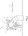
- FIG. 2 is a schematic diagram illustrating fluid flow in heat exchange system 10.
- FIGS. 1-2 will be described together.
- FIGS. 1-2 show heat exchange system 10, including heat exchanger 12, external mount 14, first duct 16, and second duct 18.
- Heat exchanger 12 includes first header 20, second header 22, core 24, mount structure 26, and exterior surface 27.
- First header 20 includes fluid inlet 28, and second header 22 includes fluid outlet 30.
- Core 24 includes core tubes 32.
- FIGS. 1-2 also show internal fluid flow path F1 and external fluid flow path F2 (shown in FIG. 2 ).
- Heat exchange system 10 includes heat exchanger 12 connected between first duct 16 and second duct 18.
- heat exchange system 10 can be on an aircraft, such as part of an aircraft environmental control system or other aircraft system.
- heat exchange system 10 can be used in any implementation for exchanging heat between fluids.
- heat exchanger 12 is attached to external mount 14 between first duct 16 and second duct 18.
- External mount 14 is an attachment portion of a structure that is external to heat exchanger 12.
- External mount 14 can take many different forms, such as a flange, a bracket, etc. suitable for attaching to heat exchanger 12.
- external mount 14 can be part of or extend from a flange or lip of an aircraft engine wall.
- First duct 16 and second duct 18 are pipes, tubes, or other passageways for containing fluid flowing into or out of heat exchanger 12.
- First duct 16 connects to a first end of heat exchanger 12
- second duct 18 connects to a second end of heat exchanger 12.
- heat exchanger 12 forms a relatively straight path between first duct 16 and second duct 18 such that first duct 16 and second duct 18 are on opposite ends of heat exchanger 12.
- heat exchanger 12 could form a curved path between ducts in any orientation with respect to one another.
- Heat exchanger 12 is connected to first duct 16 at first header 20. More specifically, first duct 16 is connected to fluid inlet 28 of first header 20. Fluid inlet 28 includes a first opening into the flow passages of heat exchanger 12. Heat exchanger 12 is similarly connected to second duct 18 at fluid outlet 30 of second header 22. Fluid outlet 30 includes a second opening into the flow passages of heat exchanger 12. As illustrated in FIG. 1 , each of first header 20 and second header 22 can be a branched or fractal header. That is, first header 20 and/or second header 22 can include a consecutively branching tubular structure that terminates in individual tubes that are continuous with corresponding individual core tubes 32 of core 24. In the example shown in FIG.
- first header 20 and second header 22 have mirrored branching structures having the same number and arrangement of sequential branches; however, it should be understood that other examples can include first header 20 and second header 22 with different respective branching structures.
- first header 20 can be any suitable type of header for directing fluid from first duct 16 into core 24 of heat exchanger 12
- second header 22 can be any suitable type of header for directing fluid from core 24 into second duct 18.
- Core 24 of heat exchanger 12 extends from first header 20 to second header 22.
- Core 24 includes core tubes 32.
- Each of core tubes 32 is an individual tube through which fluid can flow.
- each of core tubes 32 is connected to a corresponding individual tube of first header 20 at one end and to a corresponding individual tube of second header 22 at an opposite end.
- Core tubes 32 are spaced apart from adjacent tubes.
- core 24 can also include supports between ones of core tubes 32.
- Core 24 can form an overall straight path between first header 20 and second header 22 (e.g., as shown in FIG. 1 ) or can be curved or split into different portions, depending on the space (i.e., envelope) in which heat exchanger 12 will be mounted.
- Mount structure 26 is a structural portion of heat exchanger 12 for attaching heat exchanger 12 to external mount 14.
- Mount structure 26 extends between first header 20 and second header 22.
- Mount structure 26 is generally adjacent to core 24 along a side of heat exchanger 12.
- Mount structure 26 can include mating features for connecting to external mount 14.
- Mount structure 26 is configured to have adequate structural integrity for accommodating vibrational loads on heat exchanger 12.
- external mount 14 may be connected to or part of an aircraft engine.
- mount structure 26 of heat exchanger 12 can experience vibrations from the aircraft engine due to its attachment to external mount 14.
- mount structure 26 supports heat exchanger 12 in a desired position for connecting between first duct 16 and second duct 18.
- mount structure 26 can be connected to and integrally formed with ones of core tubes 32.
- Heat exchange system 10 includes two flow paths: internal fluid flow path F1 and external fluid flow path F2.
- internal fluid flow path F1 is formed by a series of continuous passages through first duct 16, heat exchanger 12, and second duct 18.
- External fluid flow path F2 surrounds and passes around components of heat exchanger 12.
- heat exchange system 10 is configured such that a first fluid flows along internal fluid flow path F 1 and a second fluid flows along external fluid flow path F2 in a crossflow arrangement. That is, internal fluid flow path F1 is generally perpendicular to external fluid flow path F2.
- heat exchange system 10 could be configured such that internal fluid flow path F1 and external fluid flow path F2 are counter-parallel and the first and second fluids would interact in a counterflow arrangement.
- Heat exchanger 12 is configured to permit the transfer of heat between the first fluid flowing along internal fluid flow path F1 and the second fluid flowing along external fluid flow path F2.
- the first and second fluids can be any type of fluids, including air, water, lubricant, fuel, or another fluid.
- the first and second fluids can be the same or different types of fluids.
- the first fluid and the second fluid can have different temperatures.
- Heat exchanger 12 is generally described herein as providing heat transfer from the first fluid to the second fluid; therefore, the first fluid can be at a greater temperature than the second fluid at the point where the first fluid enters heat exchanger 12.
- the first fluid can be around 1,000°F and the second fluid can be around 100°F or an order of magnitude lower.
- heat exchanger 12 is shown receiving the first fluid along internal fluid flow path F1 at fluid inlet 28 of first header 20. That is, first header 20 can be a relatively upstream header with respect to second header 22 along internal fluid flow path F1, and second header 22 can be a relatively downstream header. In other examples, the direction of flow of the first fluid can be reversed along internal fluid flow path F1 such that the first fluid exits rather than enters heat exchanger 12 at fluid inlet 28.
- the first fluid flows along an initial segment of internal fluid flow path F1 through first duct 16 and enters heat exchanger 12 at fluid inlet 28 of first header 20.
- the first fluid flows along an intermediate segment of internal fluid flow path F1 through the branching tubular structure of first header 20 into core tubes 32 of core 24 and-from there-into the branching tubular structure of second header 22.
- Branches of internal fluid flow path F1 are diverted via ones of core tubes 32 through mount structure 26 so that some of the first fluid passes through an internal flow passage of mount structure 26, as will be described in greater detail below.
- the first fluid flows downstream into second header 22 from core tubes 32 and is discharged from second header 22 at fluid outlet 30.
- the first fluid flows along a final segment of internal fluid flow path F1 within second duct 18.
- the flow direction of the first fluid along internal fluid flow path F1 can be reversed. Exterior surface 27 of heat exchanger 12 is exposed to the second fluid as it flows along external fluid flow path F2, as shown in FIG. 2 . Heat transfer between the first fluid and the second fluid can occur at first header 20, second header 22, core 24, and/or mount structure 26 as the first fluid flows through heat exchanger 12 along internal fluid flow path F1 and the second fluid contacts exterior surface 27 as it flows along external fluid flow path F2.
- Heat exchanger 12 and its component parts can be integrally formed partially or entirely by additive manufacturing.
- exemplary additive manufacturing processes include powder bed fusion techniques such as direct metal laser sintering (DMLS), laser net shape manufacturing (LNSM), electron beam manufacturing (EBM), to name a few, non-limiting examples.
- DMLS direct metal laser sintering
- LNSM laser net shape manufacturing
- EBM electron beam manufacturing
- SLA stereolithography
- Additive manufacturing is useful for obtaining unique geometries and for reducing the need for welds or other attachments (e.g., between a header and core).
- suitable manufacturing and/or post-manufacture machining techniques can also be used.
- heat exchanger 12 can be formed layer by layer to achieve varied dimensions (e.g., cross-sectional area, wall thicknesses, curvature, etc.) and complex internal passages and/or components, such as the internal flow passage of mount structure 26.
- Each additively manufactured layer creates a new horizontal build plane to which a subsequent layer of heat exchanger 12 is fused. That is, the build plane for the additive manufacturing process remains horizontal but shifts vertically by defined increments (e.g., one micrometer, one hundredth of a millimeter, one tenth of a millimeter, a millimeter, or other distances) as manufacturing proceeds. Therefore, heat exchanger 12, including mount structure 26, can be additively manufactured as a single, monolithic unit or part.
- heat exchanger 12 with mount structure 26 by additive manufacturing allows for the consolidation of parts and can reduce or eliminate the need for any post-process machining that is typically required with traditionally manufactured components.
- FIGS. 1-6B show heat exchangers 12, 112, 212, and 312 fully manufactured.
- FIGS. 3A-6B Each heat exchanger example shown in FIGS. 3A-6B includes several generally similar components, which share the same name and which are identified by shared reference numbers that are increased incrementally between groups of FIGS. 3A-6B (e.g., FIGS. 3A-3C include heat exchanger 12; FIGS. 4A-4C include heat exchanger 112; FIG. 5 includes heat exchanger 212; and FIGS. 6A-6B include heat exchanger 312).
- FIGS. 3A-6B include heat exchanger 312
- FIGS. 3A-6B include heat exchanger 312
- FIGS. 3A-6B can include all or any combination of the components and features described herein. Although depicted in FIGS. 3A-6B as separate examples, a heat exchanger including a mount structure according to techniques of this disclosure can generally include any combination of the following features. Additionally, although each of the heat exchanger examples shown in FIGS. 3A-6B includes a single mount structure, the same concepts can be applied to heat exchangers with multiple mount structures and are not intended to be limited to implementations with only one mount structure. Moreover, one heat exchanger could also include multiple mount structures based on a combination of the different examples described herein.
- FIG. 3A is an isometric view of heat exchanger 12 including mount structure 26 with common plenum internal flow passage 44.
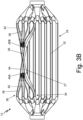
- FIG. 3B is a partial cross-sectional view of heat exchanger 112 showing details of common plenum internal flow passage 44 of mount structure 26.
- FIG. 3C is a partial cross-sectional view of mount structure 26 and connected diverted tubes 38 in isolation.
- FIGS. 3A-3C will be described together.
- FIGS. 3A-3C show heat exchanger 12 including first header 20, second header 22, core 24, mount structure 26, and exterior surface 27.
- First header 20 includes fluid inlet 28, and second header 22 includes fluid outlet 30.
- Core 24 includes core tubes 32, layers 34, and subset group of tubes 36, which includes diverted tubes 38. Diverted tubes 38 include respective first portions 40 and second portions 42.
- Mount structure 26 includes internal flow passage 44, first end 45A, second end 45B, and opening 46.
- First header 20, second header 22, core 24, mount structure 26, exterior surface 27, fluid inlet 28, fluid outlet 30, and core tubes 32 of heat exchanger 12 are described above with reference to FIGS. 1-2 .
- core tubes 32 of core 24 are arranged in layers 34.
- FIG. 3A shows eight layers 34 stacked vertically to form core 24.
- heat exchanger 12 can include more or fewer layers 34.
- Each of layers 34 includes one or more core tubes 32.
- each of layers 34 can include the same number of core tubes 32.
- FIG. 3A shows each of layers 34 includes four core tubes 32.
- layers 34 can have different numbers of core tubes 32.
- Core 24 also includes subset group of tubes 36.
- Subset group of tubes 36 is a subset of individual core tubes 32 that are connected to mount structure 26.
- Subset group of tubes 36 includes diverted tubes 38.
- Diverted tubes 38 are individual ones of core tubes 32 that are connected to mount structure 26. That is, diverted tubes 38 are diverted to mount structure 26 and remaining core tubes 32 form a non-diverted portion of core 24.
- FIG. 3A shows four core tubes 32 are diverted tubes 38. In other examples, there can be more or fewer diverted tubes 38 in subset group of tubes 36.
- FIG. 3A shows that subset group of tubes 36 includes diverted tubes 38 which are core tubes 32 from the same layer 34.
- subset group of tubes 36 can include core tubes 32 from different layers 34 (e.g., as shown in FIG. 5 and described in greater detail below). Diverted tubes 38 can be integrally formed with mount structure 26.
- Mount structure 26 is hollow and includes internal flow passage 44.
- Internal flow passage 44 is a common plenum (also referred to herein as “common plenum internal flow passage 44") through which a fluid (e.g., the first fluid described above with reference to FIGS. 1-2 ) can flow.
- Internal flow passage 44 provides flow communication through mount structure 26 between first header 20 and second header 22.
- Mount structure 26 extends from first (or relatively upstream) end 45A to second (or relatively downstream) end 45B.
- Internal flow passage 44 also extends from first end 45A to second end 45B within mount structure 26.
- Diverted tubes 38 join with mount structure 26 so that each diverted tube 38 is connected to internal flow passage 44 of mount structure 26.
- each diverted tube 38 converges into first end 45A and reemerges from second end 45B of mount structure 26 and common plenum internal flow passage 44.
- Diverted tubes 38 are connected at first end 45A and second end 45B of mount structure 26 and internal flow passage 44 to permit fluid to flow from upstream to downstream along a flow path (e.g., internal fluid flow path F1 as shown in FIGS. 1-2 ) through an interior of mount structure 26.
- a flow path e.g., internal fluid flow path F1 as shown in FIGS. 1-2
- Each diverted tube 38 includes a respective first portion 40 upstream of mount structure 26 and a respective second portion 42 downstream of mount structure 26.
- first portions 40 of diverted tubes 38 converge into first end 45A of mount structure 26 and common plenum internal flow passage 44.
- Corresponding second portions 42 of diverted tubes 38 reemerge from second end 45B of mount structure 26 and common plenum internal flow passage 44.
- ones of diverted tubes 38 can be separated or spaced apart from adjacent diverted tubes 38 at respective first portions 40 and respective second portions 42.
- Mount structure 26 can include opening 46.
- Opening 46 is an opening for engaging a portion of external mount 14 (shown in FIGS. 1-2 ) or another attachment mechanism so that heat exchanger 12 can be mounted in a heat exchange system (e.g., heat exchange system 10 shown in FIGS. 1-2 ).
- Opening 46 can be sized to fit with a corresponding attachment mechanism.
- Opening 46 extends through mount structure 26. As shown in cross-section in FIG. 3C , opening 46 is bounded by a portion of exterior surface 27 such that internal flow passage 44 of mount structure 44 is formed around opening 46.
- portions of a fluid flowing through heat exchanger 12 are diverted to pass though mount structure 26. That is, portions of the fluid flowing through heat exchanger 12 from first header 20 through diverted tubes 38 of subset group of tubes 36 will pass through first portions 40, into and through common plenum internal flow passage 44 of mount structure 26, and out through second portions 42 to second header 22. Accordingly, the portions of the fluid that flow through diverted tubes 38 are merged into common plenum internal flow passage 44. The portions of the fluid are merged in internal flow passage 44 at first end 45A of mount structure 26 where fluid enters from first portions 40. The merged fluid flowing through internal flow passage 44 will flow around opening 46.
- Internal flow passage 44 is integrally formed with diverted tubes 38 of subset group of tubes 36 such that internal flow passage 44 is in flow communication with first header 20 and second header 22.
- Fluid flowing through heat exchanger 12 flows from first header 20 through a main portion of core 24 to second header 22 and also along a parallel portion of the flow path from first header 20 through diverted tubes 38 and mount structure 26 to second header 22.
- first header 20, second header 22, core 24, and mount structure 26 are all in flow communication. Fluid flow through internal flow passage 44 of mount structure 26 is in parallel to fluid flow through the rest (or a non-diverted portion) of core 24.
- Heat exchanger 12 utilizes internal flow passage 44 through mount structure 26 to reduce thermal gradients across mount structure 26.
- mount structure 26 By passing internal fluid flow through internal flow passage 44 of mount structure 26, mount structure 26 is able to maintain a more uniform temperature with the rest of heat exchanger 12.
- Internal fluid flow passing through internal flow passage 44 of mount structure 26 also helps stabilize mount structure 26 at an operating temperature more rapidly, reducing the loads experienced during thermal transient conditions.
- Mount structure 26 including internal flow passage 44 can have reduced thermal stress in areas where mount structure 26 is attached to core 24.
- mount structure 26 can have a faster response to thermal transients and can also be more tolerant of high temperature external flow compared to traditional heat exchanger mounts that do not include internal flow passages.
- mount structure 26 including internal flow passage 44 provides additional heat exchange surface for increased heat transfer by heat exchanger 12. Integrally forming mount structure 26 with diverted tubes 38 from core 24 also results in heat exchanger 12 having improved packaging for fitment into more compact spaces. Heat exchanger 12 therefore balances structural, thermal, and packing requirements for effective heat exchange.
- heat exchanger 12 including mount structure 26 with common plenum internal flow passage 44 can have improved fluid mixing characteristics, which can provide different overall heat exchanger thermodynamic performance that may be desirable for certain implementations.
- FIG. 4A is an isometric view of heat exchanger 112 including mount structure 126 with multiple internal flow passages 144.
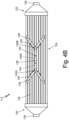
- FIG. 4B is a top view of heat exchanger 112.
- FIG. 4C is a partial cross-sectional side view of heat exchanger 112 showing details of the multiple internal flow passages 144 of mount structure 126.
- FIGS. 4A-4C will be described together.
- FIGS. 4A-4C show heat exchanger 112 including first header 120, second header 122, core 124, mount structure 126, and exterior surface 127.
- First header 120 includes fluid inlet 128, and second header 122 includes fluid outlet 130.
- Core 124 includes core tubes 132, layers 134, and subset group of tubes 136, which includes diverted tubes 138.
- Diverted tubes 138 include respective first portions 140, second portions 142, and third portions 143.
- Mount structure 126 includes internal flow passages 144 (including individual tubular passages 144A-144D), first end 145 A, second end 145B, opening 146, and free mount surface 148.
- FIG. 4A also shows free mount surface width W, third portion diameter D, core tube length L1, and diverted tube length L2.
- Heat exchanger 112 has a generally similar structure, design, and function to heat exchanger 12 described above with reference to FIGS. 1-3C , except mount structure 126 includes multiple internal flow passages 144 instead of common plenum internal flow passage 44 (as shown in FIGS. 3A-3C ).
- mount structure 126 includes multiple internal flow passages 144.
- Internal flow passages 144 include individual tubular passages 144A-144D.
- FIGS. 4A-4C show four individual tubular passages 144A-144D; however, it should be understood that other examples can include more or fewer individual tubular passages.
- the number of individual tubular passages can be selected to minimize the surface area of mount structure 126 that corresponds to free mount surface 148 and to maximize the surface area of mount structure 126 that corresponds to the individual tubular passages.
- a fluid (e.g., the first fluid described above with refence to FIGS. 1-2 ) can flow through individual tubular passages 144A-144D of internal flow passages 144.
- Individual tubular passages 144A-144D of internal flow passages 144 provide flow communication through mount structure 126 between first header 120 and second header 122.
- Mount structure 126 extends from first (or relatively upstream) end 145A to second (or relatively downstream) end 145B.
- Individual tubular passages 144A-144D of internal flow passages 144 also extend from first end 145A to second end 145B within mount structure 126.
- Diverted tubes 138 join with mount structure 126 so that each diverted tube 138 is connected to a corresponding individual tubular passage 144A-144D of internal flow passages 144. Diverted tubes 138 are connected at first end 145A and second end 145B of mount structure 126 and individual tubular passages 144A-144D to permit fluid to flow from upstream to downstream along a flow path (e.g., internal fluid flow path F1 as shown in FIGS. 1-2 ) through an interior of mount structure 126.
- a flow path e.g., internal fluid flow path F1 as shown in FIGS. 1-2
- Each diverted tube 138 includes a respective first portion 140 upstream of mount structure 126, a respective second portion 142 downstream of mount structure 126, and a respective third portion 143 that extends through mount structure 126 as a corresponding individual tubular passage 144A-144D of internal flow passages 144. That is, respective first portions 140 and second portions 142 are connected to opposite ends of respective third portions 143. Each third portion 143 is one of individual tubular passages 144A-144D. Flow passages through diverted tubes 138 are continuous from first portions 140, through third portions 143 (as individual tubular passages 144A-144D of mount structure 126), and through second portions 142.
- Flow passages through diverted tubes 138 remain separate within mount structure 126 as individual tubular passages 144A-144D, rather than merging into a common plenum (e.g., as shown in FIGS. 3A-3C ).
- ones of diverted tubes 138 can be separated or spaced apart from adjacent diverted tubes 138 at respective first portions 140 and respective second portions 412.
- each diverted tube 138 is connected to adjacent diverted tubes 138 at respective third portions 143 by free mount surface 148 extending between respective third portions 143 of adjacent diverted tubes 138.
- Free mount surface 148 encompasses the portions of mount structure 126 that do not have internal flow passages 144 passing through.
- Free mount surface 148 includes the structural portions of mount structure 126 that span between third portions 143 of diverted tubes 138 as they extend through mount structure 126. As shown in FIG. 4A , free mount surface 148 has width W. Third portions 143 of diverted tubes 138 also have diameter D as measured in the same direction as width W. In some examples, free mount surface width W is less than diameter D of third portions 143 (i.e., free mount surface 148 is narrower than third portions 143) so that individual tubular passages 144A-144D retain the individual tubular characteristics of core tubes 132. In other examples, free mount surface width W and diameter D can have any suitable relative dimensions.
- Mount structure 126 can also include opening 146.
- Opening 146 is an opening for engaging a portion of external mount 14 (shown in FIGS. 1-2 ) or another attachment mechanism so that heat exchanger 112 can be mounted in a heat exchange system (e.g., heat exchange system 10 shown in FIGS. 1-2 ).
- Opening 146 can be sized to fit with a corresponding attachment mechanism.
- Opening 146 extends through mount structure 126. As is most easily viewed in FIG. 4C , individual tubular passages 144A-144D of internal flow passages 144 (and corresponding third portions 143 of diverted tubes 138) are routed around opening 146.
- individual tubular passages 144A-144D and corresponding third portions 143 can be curved or contoured around opening 146.
- FIG. 4C shows each of individual tubular passages 144A-144D is curved, and individual tubular passages 144B and 144C are more significantly curved than individual tubular passages 144Aand 144D.
- individual tubular passages 144A-144D and corresponding third portions 143 can be sufficiently spaced away from opening 146 to have straight paths through mount structure 126.
- core tubes 132 that are not diverted to mount structure 126 have length L1.
- Diverted tubes 138 of subset group of tubes 136 have length L2.
- diverted tubes 138 of subset group of tubes 136 can be longer than the remaining core tubes 132 that are not diverted to mount structure 126, i.e., length L2 can be greater than length L1.
- Length L2 of diverted tubes 138 can be greater than length L1 of remaining core tubes 132 because diverted tubes 138 turn at some point along their length toward mount structure 126, rather than following the shortest path from first header 120 to second header 122.
- Diverted tubes 138 may also be angled away from the remaining core tubes 132 depending on the arrangement of internal flow passages 144 through mount structure 126.
- portions of a fluid flowing through heat exchanger 112 are diverted to pass though mount structure 126. That is, portions of the fluid flowing through heat exchanger 112 from first header 120 through diverted tubes 138 of subset group of tubes 136 will pass through first portions 140, into and through third portions 143 at mount structure 126, and out through second portions 142 to second header 122. The portions of fluid remain separated in individual tubular passages 144A-144D of internal flow passages 144 (i.e., within third portions 143). Internal flow passages 144 are integrally formed with diverted tubes 138 of subset group of tubes 136 such that internal flow passages 144 are in flow communication with first header 120 and second header 122.
- Fluid flowing through heat exchanger 112 flows from first header 120 through a main portion of core 124 to second header 122 and also along a parallel portion of the flow path from first header 120 through diverted tubes 138 and mount structure 126 to second header 122.
- first header 120, second header 122, core 124, and mount structure 126 are all in flow communication.
- Fluid flow through internal flow passages 144 of mount structure 26 is in parallel to fluid flow through the rest (or a non-diverted portion) of core 124.
- diverted tubes 138 routed through mount structure 126 can provide additional heat exchanging capacity because diverted tubes 138 are longer than other core tubes 132 and therefore have more surface area available for heat transfer. Moreover, the longer, straighter segments of diverted tubes 138 are relatively strong so as to be suitable for durably connecting to mount structure 126 away from the remaining core tubes 132.
- FIG. 5 is an isometric view of heat exchanger 212 including mount structure 226 with multiple internal flow passages 244 that are connected to diverted tubes 238 arising from multiple core layers 234.
- FIG. 5 shows heat exchanger 212 including first header 220, second header 222, core 224, mount structure 226, and exterior surface 227.
- First header 220 includes fluid inlet 228, and second header 222 includes fluid outlet 230.
- Core 224 includes core tubes 232, layers 234, and subset group of tubes 236, which includes diverted tubes 238.
- Diverted tubes 238 include respective first portions 240, second portions 242, and third portions 243.
- Mount structure 226 includes internal flow passages 244 (including individual tubular passages 244A-244D), first end 245A, second end 245B, opening 246, and free mount surface 248. Also labeled in FIG. 5 is inward tube 249.
- Heat exchanger 212 has a generally similar structure, design, and function to heat exchanger 112 described above with reference to FIGS. 4A-4C , except diverted tubes 238 arise from multiple core layers 234 rather than from a single core layer 34 or 134, as shown in FIGS. 3A-4C . That is, subset group of tubes 236 includes a subset of individual core tubes 232 from multiple layers 234 in core 224. In the example shown in FIG. 5 , diverted tubes 238 of subset group of tubes 236 are ones of core tubes 232 arising from three different layers 234. Specifically, the example shown in FIG.
- FIG. 5 shows four diverted tubes 238, three of which arise from different layers 234, along with inward tube 249, which is one of diverted tubes 238 that arises from the same layer 234 as another diverted tube 238 but from a laterally inward position within the same layer 234.
- inward tube 249 which is one of diverted tubes 238 that arises from the same layer 234 as another diverted tube 238 but from a laterally inward position within the same layer 234.
- any combination of core tubes 232 in any layers 234 can be routed to mount structure 226 as diverted tubes 238.
- subset group of tubes 236 can include ones of core tubes 232 that are configured to be positioned proximate to an external mount (e.g., external mount 14 shown in FIGS.
- heat exchanger 212 when heat exchanger 212 is installed in a heat exchange system (e.g., heat exchange system 10 shown in FIGS. 1-2 ).
- the position of an external mount or other structure may dictate the corresponding position of mount structure 226 with respect to the rest of heat exchanger 212 and therefore determine the ones of core tubes 232 that will be nearest to mount structure 226.
- mount structure 226 can be positioned in any orientation with respect to core 224 and the rest of heat exchanger 212.
- diverted tubes 238 are ones of core tubes 232 that are proximate mount structure 226.
- diverted tubes 238 routed through mount structure 226 that arise from multiple core layers 234 allow heat exchanger 212 to have more flexible design options for connecting core tubes 232 to mount structure 226.
- heat exchanger 212 including mount structure 226 and diverted tubes 238 can be implemented in spaces where structural implications would otherwise make it difficult to route fluid flow to the location where the mount structure needs to be positioned, such as compact or irregularly shaped spaces.
- including inward tube 249 (or multiple core tubes 232 that are positioned more interiorly) in subset group of tubes 236 can improve the strength of mount structure 226 while maintaining heat exchange benefits from internal flow passages 244.
- inward tube 249 in subset group of tubes 236 may also further reduce the thermal gradient experienced by mount structure 226.
- the ability to utilize core tubes 232 from different layers 234 or different lateral positions within core 224 in subset group of tubes 236 makes the thermodynamics of mount structure 226 tunable for different implementations of heat exchanger 212.
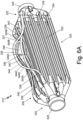
- FIG. 6A is an isometric view of heat exchanger 312 including mount structure 326 with multiple internal flow passages 344 and contoured diverted tubes 338 connected to mount structure 326.
- FIG. 6B is a top view of the fourth example of the heat exchanger.
- FIGS. 6A-6B will be described together.
- FIGS. 6A-6B show heat exchanger 312 including first header 320, second header 322, core 324, mount structure 326, and exterior surface 327.
- First header 320 includes fluid inlet 328
- second header 322 includes fluid outlet 330.
- Core 324 includes core tubes 332, layers 334, and subset group of tubes 336, which includes diverted tubes 338.
- Diverted tubes 338 include respective first portions 340, second portions 342, and third portions 343.
- Mount structure 326 includes internal flow passages 344 (including individual tubular passages 344A-344D), first end 345A, second end 345B, opening 346, and free mount surface 348.
- Heat exchanger 312 has a generally similar structure, design, and function to heat exchanger 112 described above with reference to FIGS. 4A-4C , except diverted tubes 338 are contoured. As shown in FIGS. 6A-6B , first portions 340 of diverted tubes 338 are contoured along the length from first header 320 to mount structure 326. Likewise, second portions 342 of diverted tubes 338 are also contoured along the length from mount structure 326 to second header 330. This contrasts with diverted tubes 138 shown in FIGS. 4A-4C , which have a turn between two straight segments in each of first portions 140 and second portions 142. In some examples, first portions 340 and second portions 342 are contoured along the entire segment. In other examples, either first portions 340 or second portions 342 can be contoured and the other can have straight segments.
- contoured diverted tubes 338 also allow heat exchanger 312 to have more flexible design options for connecting core tubes 332 to mount structure 326. In this way, heat exchanger 312 including mount structure 326 and contoured diverted tubes 338 can be implemented in spaces where structural implications would otherwise make it difficult to route fluid flow to the location where the mount structure needs to be positioned, such as compact or irregularly shaped spaces.
- a heat exchanger includes a first header including a fluid inlet and a second header positioned downstream of the first header with respect to a first flow path of a first fluid and including a fluid outlet.
- the heat exchanger further includes a core extending from the first header to the second header and a mount structure extending between the first header and the second header.
- the core includes a plurality of core tubes.
- the mount structure is integrally formed with a subset group of diverted tubes of the plurality of core tubes and includes one or more internal flow passages that are connected to the subset group of diverted tubes such that the one or more internal flow passages are in flow communication with the first header and the second header in parallel to a non-diverted portion of the core.
- the heat exchanger of the preceding paragraph can optionally include, additionally and/or alternatively, any one or more of the following features, configurations and/or additional components:
- the one or more internal flow passages can include a common plenum within the mount structure that is connected to each tube of the subset group of diverted tubes such that portions of the first fluid flowing through the subset group of diverted tubes are merged in the common plenum.
- Each tube of the subset group of diverted tubes can converge into a first end of the common plenum and reemerge from a second end of the common plenum such that each tube of the subset group of diverted tubes includes a first portion upstream of the mount structure and a second portion downstream of the mount structure.
- Each tube of the subset group of diverted tubes can be separated from adj acent tubes of the subset group of diverted tubes at a respective first portion and a respective second portion.
- the one or more internal flow passages can include individual tubular passages that are each connected to a corresponding tube of the subset group of diverted tubes such that each tube of the subset group of diverted tubes includes a first portion upstream of the mount structure, a second portion downstream of the mount structure, and a third portion that extends through the mount structure as a corresponding individual tubular passage of the one or more internal flow passages.
- Each tube of the subset group of diverted tubes can be separated from adj acent tubes of the subset group of diverted tubes at a respective first portion and a respective second portion; and each tube of the subset group of diverted tubes can be connected to the adjacent tubes of the subset group of diverted tubes by free mount surface extending between respective third portions of each tube of the subset group of diverted tubes.
- the free mount surface can have a width that is less than a diameter of the third portion of each tube of the subset group of diverted tubes.
- Each tube of the subset group of diverted tubes can be longer than remaining tubes of the plurality of core tubes.
- Each of the individual tubular passages of the mount structure can be routed around an opening through the mount structure.
- the first or second portion of each tube of the subset group of diverted tubes can be contoured.
- the subset group of diverted tubes can include individual core tubes from a same layer in the core.
- the subset group of diverted tubes can include individual core tubes from multiple layers in the core.
- the subset group of diverted tubes can include individual core tubes that are configured to be positioned proximate to an external mount when the heat exchanger is installed in a heat exchange system.
- the heat exchanger including the mount structure can be configured to be additively manufactured as a single, monolithic unit.
- At least one of the first header and the second header can be a fractal header.
- At least one of the first header and the second header can include a consecutively branching tubular structure terminating in individual tubes that are continuous with corresponding ones of the plurality of core tubes.
- the first header can be configured to receive the first fluid via the fluid inlet and the second header can be configured to discharge the first fluid via the fluid outlet; and an exterior surface of the heat exchanger can be exposed to a second fluid in a crossflow arrangement.
- the first fluid and the second fluid can have different temperatures.
- a heat exchanger includes a first header including a fluid inlet and a second header positioned downstream of the first header with respect to a first flow path of a first fluid and including a fluid outlet.
- the heat exchanger further includes a core extending from the first header to the second header and a mount structure positioned adjacent to the core.
- the core includes a plurality of core tubes.
- the mount structure is integrally formed with a subset group of diverted tubes of the plurality of core tubes and includes one or more internal flow passages that are connected to the subset group of diverted tubes such that the first flow path is diverted through the one or more internal flow passages of the mount structure.
- a heat exchange system includes a heat exchanger and an external mount.
- the heat exchanger includes a first header including a fluid inlet and a second header positioned downstream of the first header with respect to a first flow path of a first fluid and including a fluid outlet.
- the heat exchanger further includes a core extending between the first header and the second header and a mount structure.
- the core includes a plurality of core tubes.
- the mount structure is integrally formed with a subset group of diverted tubes of the plurality of core tubes and includes one or more internal flow passages that are connected to the subset group of diverted tubes such that the one or more internal flow passages are in flow communication with the first header and the second header in parallel to a non-diverted portion of the core.
- the external mount is positioned along a second flow path of a second fluid and attached to the mount structure of the heat exchanger such that that heat exchanger is mounted in a crossflow arrangement with respect to the second flow path.
Landscapes
- Engineering & Computer Science (AREA)
- Physics & Mathematics (AREA)
- Thermal Sciences (AREA)
- Mechanical Engineering (AREA)
- General Engineering & Computer Science (AREA)
- Chemical & Material Sciences (AREA)
- Manufacturing & Machinery (AREA)
- Materials Engineering (AREA)
- Heat-Exchange Devices With Radiators And Conduit Assemblies (AREA)
Abstract
Description
- The present disclosure relates generally to heat exchangers, and more specifically to heat exchanger mount structures.
- Heat exchangers are used in many industries for a variety of applications. In mobile applications, particularly for aerospace applications, heat exchangers may be used to provide compact, low-weight, and highly-effective means of exchanging heat from a hot fluid to a cold fluid. Heat exchangers may also operate in high temperature environments, for example, in modern aircraft engines, and thus may be exposed to high thermal stresses. Additive manufacturing techniques can be utilized to manufacture heat exchangers layer by layer to obtain a variety of complex heat exchanger geometries.
- In one example, a heat exchanger includes a first header including a fluid inlet and a second header positioned downstream of the first header with respect to a first flow path of a first fluid and including a fluid outlet. The heat exchanger further includes a core extending from the first header to the second header and a mount structure extending between the first header and the second header. The core includes a plurality of core tubes. The mount structure is integrally formed with a subset group of diverted tubes of the plurality of core tubes and includes one or more internal flow passages that are connected to the subset group of diverted tubes such that the one or more internal flow passages are in flow communication with the first header and the second header in parallel to a non-diverted portion of the core.
- In another example, a heat exchanger includes a first header including a fluid inlet and a second header positioned downstream of the first header with respect to a first flow path of a first fluid and including a fluid outlet. The heat exchanger further includes a core extending from the first header to the second header and a mount structure positioned adjacent to the core. The core includes a plurality of core tubes. The mount structure is integrally formed with a subset group of diverted tubes of the plurality of core tubes and includes one or more internal flow passages that are connected to the subset group of diverted tubes such that the first flow path is diverted through the one or more internal flow passages of the mount structure.
- In another example, a heat exchange system includes a heat exchanger and an external mount. The heat exchanger includes a first header including a fluid inlet and a second header positioned downstream of the first header with respect to a first flow path of a first fluid and including a fluid outlet. The heat exchanger further includes a core extending between the first header and the second header and a mount structure. The core includes a plurality of core tubes. The mount structure is integrally formed with a subset group of diverted tubes of the plurality of core tubes and includes one or more internal flow passages that are connected to the subset group of diverted tubes such that the one or more internal flow passages are in flow communication with the first header and the second header in parallel to a non-diverted portion of the core. The external mount is positioned along a second flow path of a second fluid and attached to the mount structure of the heat exchanger such that that heat exchanger is mounted in a crossflow arrangement with respect to the second flow path.
-
-
FIG. 1 is a schematic diagram illustrating a heat exchanger mounted in a heat exchange system. -
FIG. 2 is a schematic diagram illustrating fluid flow in the heat exchange system ofFIG. 1 . -
FIG. 3A is an isometric view of a first example of a heat exchanger including a mount structure with a common plenum internal flow passage. -
FIG. 3B is a partial cross-sectional view of the first example of the heat exchanger showing details of the common plenum internal flow passage of the mount structure. -
FIG. 3C is a partial cross-sectional view of the mount structure and connected diverted tubes ofFIG. 3A in isolation. -
FIG. 4A is an isometric view of a second example of a heat exchanger including a mount structure with multiple internal flow passages. -
FIG. 4B is a top view of the second example of the heat exchanger. -
FIG. 4C is a partial cross-sectional side view of the second example of the heat exchanger showing details of the multiple internal flow passages of the mount structure. -
FIG. 5 is an isometric view of a third example of a heat exchanger including a mount structure with multiple internal flow passages that are connected to diverted tubes arising from multiple core layers. -
FIG. 6A is an isometric view of a fourth example of a heat exchanger including a mount structure with multiple internal flow passages and contoured diverted tubes connected to the mount structure. -
FIG. 6B is a top view of the fourth example of the heat exchanger. - Heat exchangers that operate in certain environments, such as in modern aircraft engines, can have reduced service lives due to fatigue caused by cyclic loading conditions while in operation and/or fatigue caused during manufacture. For example, components of heat exchangers can be subjected to high cycle fatigue (HCF) and low cycle fatigue (LCF). Fatigue can be caused by vibrational stress and/or thermal stress experienced by the component. Thermal stress can be either steady state or transient. Steady state thermal stress is due to a substantially constant difference in temperature over time. Transient thermal stress is due to a sudden or periodic change in temperature that the component experiences.
- Additively manufactured heat exchangers with fractal headers are often designed to operate to stringent HCF or vibrational load and LCF or thermal load conditions. Because the core of a fractal heat exchanger consists of numerous flexible heat-exchanging members, additional mounts to external structures are often required to meet HCF requirements. These mounts that are driven by HCF requirements can be detrimental to LCF performance due to the thermal gradient between the mount material and the heat transfer surface of the heat exchanger. As heat exchangers are pushed to tolerate larger thermal gradients over shorter durations, the transient thermal stresses tend to increase. The highest stress is generally experienced at the attachment between the mount and the heat exchanger core with traditional mounts that are only directly exposed to external flow being connected to heat exchangers that have internal flow.
- As described herein, a heat exchanger mount structure includes one or more internal flow passages, such that fluid flowing through the heat exchanger passes through the mount. The mount structure including the one or more internal flow passages maintains a more uniform temperature with the rest of the heat exchanger and can therefore meet vibrational and thermal load requirements for additively manufactured fractal heat exchangers. Heat exchangers including mount structures with internal flow passages according to techniques of this disclosure are described below with reference to
FIGS. 1-6B . -
FIG. 1 is a schematic diagram illustratingheat exchanger 12 mounted inheat exchange system 10.FIG. 2 is a schematic diagram illustrating fluid flow inheat exchange system 10.FIGS. 1-2 will be described together.FIGS. 1-2 showheat exchange system 10, includingheat exchanger 12,external mount 14,first duct 16, andsecond duct 18.Heat exchanger 12 includesfirst header 20,second header 22,core 24,mount structure 26, andexterior surface 27.First header 20 includesfluid inlet 28, andsecond header 22 includesfluid outlet 30. Core 24 includescore tubes 32.FIGS. 1-2 also show internal fluid flow path F1 and external fluid flow path F2 (shown inFIG. 2 ). -
Heat exchange system 10 includesheat exchanger 12 connected betweenfirst duct 16 andsecond duct 18. In some examples,heat exchange system 10 can be on an aircraft, such as part of an aircraft environmental control system or other aircraft system. In other examples,heat exchange system 10 can be used in any implementation for exchanging heat between fluids. As illustrated inFIG. 1 ,heat exchanger 12 is attached toexternal mount 14 betweenfirst duct 16 andsecond duct 18.External mount 14 is an attachment portion of a structure that is external toheat exchanger 12.External mount 14 can take many different forms, such as a flange, a bracket, etc. suitable for attaching toheat exchanger 12. For example,external mount 14 can be part of or extend from a flange or lip of an aircraft engine wall. -
First duct 16 andsecond duct 18 are pipes, tubes, or other passageways for containing fluid flowing into or out ofheat exchanger 12.First duct 16 connects to a first end ofheat exchanger 12, andsecond duct 18 connects to a second end ofheat exchanger 12. As illustrated inFIG. 1 ,heat exchanger 12 forms a relatively straight path betweenfirst duct 16 andsecond duct 18 such thatfirst duct 16 andsecond duct 18 are on opposite ends ofheat exchanger 12. In other examples,heat exchanger 12 could form a curved path between ducts in any orientation with respect to one another. -
Heat exchanger 12 is connected tofirst duct 16 atfirst header 20. More specifically,first duct 16 is connected tofluid inlet 28 offirst header 20.Fluid inlet 28 includes a first opening into the flow passages ofheat exchanger 12.Heat exchanger 12 is similarly connected tosecond duct 18 atfluid outlet 30 ofsecond header 22.Fluid outlet 30 includes a second opening into the flow passages ofheat exchanger 12. As illustrated inFIG. 1 , each offirst header 20 andsecond header 22 can be a branched or fractal header. That is,first header 20 and/orsecond header 22 can include a consecutively branching tubular structure that terminates in individual tubes that are continuous with correspondingindividual core tubes 32 ofcore 24. In the example shown inFIG. 1 ,first header 20 andsecond header 22 have mirrored branching structures having the same number and arrangement of sequential branches; however, it should be understood that other examples can includefirst header 20 andsecond header 22 with different respective branching structures. In yet other examples,first header 20 can be any suitable type of header for directing fluid fromfirst duct 16 intocore 24 ofheat exchanger 12, andsecond header 22 can be any suitable type of header for directing fluid fromcore 24 intosecond duct 18. -
Core 24 ofheat exchanger 12 extends fromfirst header 20 tosecond header 22.Core 24 includescore tubes 32. Each ofcore tubes 32 is an individual tube through which fluid can flow. Moreover, each ofcore tubes 32 is connected to a corresponding individual tube offirst header 20 at one end and to a corresponding individual tube ofsecond header 22 at an opposite end.Core tubes 32 are spaced apart from adjacent tubes. Although not shown inFIG. 1 ,core 24 can also include supports between ones ofcore tubes 32.Core 24 can form an overall straight path betweenfirst header 20 and second header 22 (e.g., as shown inFIG. 1 ) or can be curved or split into different portions, depending on the space (i.e., envelope) in whichheat exchanger 12 will be mounted. -
Mount structure 26 is a structural portion ofheat exchanger 12 for attachingheat exchanger 12 toexternal mount 14.Mount structure 26 extends betweenfirst header 20 andsecond header 22.Mount structure 26 is generally adjacent tocore 24 along a side ofheat exchanger 12.Mount structure 26 can include mating features for connecting toexternal mount 14.Mount structure 26 is configured to have adequate structural integrity for accommodating vibrational loads onheat exchanger 12. For example,external mount 14 may be connected to or part of an aircraft engine. In such examples, mountstructure 26 ofheat exchanger 12 can experience vibrations from the aircraft engine due to its attachment toexternal mount 14. Whenheat exchanger 12 is mounted inheat exchange system 10,mount structure 26 supportsheat exchanger 12 in a desired position for connecting betweenfirst duct 16 andsecond duct 18. As will be described in greater detail below, mountstructure 26 can be connected to and integrally formed with ones ofcore tubes 32. -
Heat exchange system 10 includes two flow paths: internal fluid flow path F1 and external fluid flow path F2. In general, internal fluid flow path F1 is formed by a series of continuous passages throughfirst duct 16,heat exchanger 12, andsecond duct 18. External fluid flow path F2 surrounds and passes around components ofheat exchanger 12. As illustrated inFIGS. 1-2 ,heat exchange system 10 is configured such that a first fluid flows along internal fluid flow path F 1 and a second fluid flows along external fluid flow path F2 in a crossflow arrangement. That is, internal fluid flow path F1 is generally perpendicular to external fluid flow path F2. Alternatively,heat exchange system 10 could be configured such that internal fluid flow path F1 and external fluid flow path F2 are counter-parallel and the first and second fluids would interact in a counterflow arrangement. -
Heat exchanger 12 is configured to permit the transfer of heat between the first fluid flowing along internal fluid flow path F1 and the second fluid flowing along external fluid flow path F2. The first and second fluids can be any type of fluids, including air, water, lubricant, fuel, or another fluid. Moreover, the first and second fluids can be the same or different types of fluids. The first fluid and the second fluid can have different temperatures.Heat exchanger 12 is generally described herein as providing heat transfer from the first fluid to the second fluid; therefore, the first fluid can be at a greater temperature than the second fluid at the point where the first fluid entersheat exchanger 12. In one example, the first fluid can be around 1,000°F and the second fluid can be around 100°F or an order of magnitude lower. However, other heat exchange configurations ofheat exchange system 10 can include the second fluid at a greater temperature than the first fluid. Additionally, in the example shown inFIGS. 1-2 ,heat exchanger 12 is shown receiving the first fluid along internal fluid flow path F1 atfluid inlet 28 offirst header 20. That is,first header 20 can be a relatively upstream header with respect tosecond header 22 along internal fluid flow path F1, andsecond header 22 can be a relatively downstream header. In other examples, the direction of flow of the first fluid can be reversed along internal fluid flow path F1 such that the first fluid exits rather than entersheat exchanger 12 atfluid inlet 28. - In operation, the first fluid flows along an initial segment of internal fluid flow path F1 through
first duct 16 and entersheat exchanger 12 atfluid inlet 28 offirst header 20. The first fluid flows along an intermediate segment of internal fluid flow path F1 through the branching tubular structure offirst header 20 intocore tubes 32 ofcore 24 and-from there-into the branching tubular structure ofsecond header 22. Branches of internal fluid flow path F1 are diverted via ones ofcore tubes 32 throughmount structure 26 so that some of the first fluid passes through an internal flow passage ofmount structure 26, as will be described in greater detail below. The first fluid flows downstream intosecond header 22 fromcore tubes 32 and is discharged fromsecond header 22 atfluid outlet 30. The first fluid flows along a final segment of internal fluid flow path F1 withinsecond duct 18. Alternatively, the flow direction of the first fluid along internal fluid flow path F1 can be reversed.Exterior surface 27 ofheat exchanger 12 is exposed to the second fluid as it flows along external fluid flow path F2, as shown inFIG. 2 . Heat transfer between the first fluid and the second fluid can occur atfirst header 20,second header 22,core 24, and/or mountstructure 26 as the first fluid flows throughheat exchanger 12 along internal fluid flow path F1 and the second fluid contactsexterior surface 27 as it flows along external fluid flow path F2. -
Heat exchanger 12 and its component parts (e.g.,first header 20,second header 22,core 24, and mount structure 26) can be integrally formed partially or entirely by additive manufacturing. For metal components (e.g., nickel-based superalloys, aluminum, titanium, etc.) exemplary additive manufacturing processes include powder bed fusion techniques such as direct metal laser sintering (DMLS), laser net shape manufacturing (LNSM), electron beam manufacturing (EBM), to name a few, non-limiting examples. For polymer or plastic components, stereolithography (SLA) can be used. Additive manufacturing is useful for obtaining unique geometries and for reducing the need for welds or other attachments (e.g., between a header and core). However, it should be understood that other suitable manufacturing and/or post-manufacture machining techniques can also be used. - During an additive manufacturing process,
heat exchanger 12 can be formed layer by layer to achieve varied dimensions (e.g., cross-sectional area, wall thicknesses, curvature, etc.) and complex internal passages and/or components, such as the internal flow passage ofmount structure 26. Each additively manufactured layer creates a new horizontal build plane to which a subsequent layer ofheat exchanger 12 is fused. That is, the build plane for the additive manufacturing process remains horizontal but shifts vertically by defined increments (e.g., one micrometer, one hundredth of a millimeter, one tenth of a millimeter, a millimeter, or other distances) as manufacturing proceeds. Therefore,heat exchanger 12, includingmount structure 26, can be additively manufactured as a single, monolithic unit or part. The integral formation ofheat exchanger 12 withmount structure 26 by additive manufacturing allows for the consolidation of parts and can reduce or eliminate the need for any post-process machining that is typically required with traditionally manufactured components.FIGS. 1-6B show heat exchangers - Several examples of heat exchangers including mount structures according to techniques of this disclosure will be described with reference to
FIGS. 3A-6B . Each heat exchanger example shown inFIGS. 3A-6B includes several generally similar components, which share the same name and which are identified by shared reference numbers that are increased incrementally between groups ofFIGS. 3A-6B (e.g.,FIGS. 3A-3C includeheat exchanger 12;FIGS. 4A-4C includeheat exchanger 112;FIG. 5 includesheat exchanger 212; andFIGS. 6A-6B include heat exchanger 312). For ease of discussion, details of some components of the heat exchanger examples shown inFIGS. 3A-6B may not be repeated in each of the following sections, but it should be understood that the heat exchanger examples shown inFIGS. 3A-6B can include all or any combination of the components and features described herein. Although depicted inFIGS. 3A-6B as separate examples, a heat exchanger including a mount structure according to techniques of this disclosure can generally include any combination of the following features. Additionally, although each of the heat exchanger examples shown inFIGS. 3A-6B includes a single mount structure, the same concepts can be applied to heat exchangers with multiple mount structures and are not intended to be limited to implementations with only one mount structure. Moreover, one heat exchanger could also include multiple mount structures based on a combination of the different examples described herein. -
FIG. 3A is an isometric view ofheat exchanger 12 includingmount structure 26 with common plenuminternal flow passage 44.FIG. 3B is a partial cross-sectional view ofheat exchanger 112 showing details of common plenuminternal flow passage 44 ofmount structure 26.FIG. 3C is a partial cross-sectional view ofmount structure 26 and connected divertedtubes 38 in isolation.FIGS. 3A-3C will be described together.FIGS. 3A-3C show heat exchanger 12 includingfirst header 20,second header 22,core 24,mount structure 26, andexterior surface 27.First header 20 includesfluid inlet 28, andsecond header 22 includesfluid outlet 30.Core 24 includescore tubes 32, layers 34, and subset group oftubes 36, which includes divertedtubes 38. Divertedtubes 38 include respectivefirst portions 40 andsecond portions 42.Mount structure 26 includesinternal flow passage 44,first end 45A,second end 45B, andopening 46. -
First header 20,second header 22,core 24,mount structure 26,exterior surface 27,fluid inlet 28,fluid outlet 30, andcore tubes 32 ofheat exchanger 12 are described above with reference toFIGS. 1-2 . - As illustrated in
FIG. 3A ,core tubes 32 ofcore 24 are arranged inlayers 34. For example,FIG. 3A shows eightlayers 34 stacked vertically to formcore 24. In other examples,heat exchanger 12 can include more orfewer layers 34. Each oflayers 34 includes one ormore core tubes 32. In some examples, each oflayers 34 can include the same number ofcore tubes 32. For example,FIG. 3A shows each oflayers 34 includes fourcore tubes 32. In other examples, layers 34 can have different numbers ofcore tubes 32. -
Core 24 also includes subset group oftubes 36. Subset group oftubes 36 is a subset ofindividual core tubes 32 that are connected to mountstructure 26. Subset group oftubes 36 includes divertedtubes 38. Divertedtubes 38 are individual ones ofcore tubes 32 that are connected to mountstructure 26. That is, divertedtubes 38 are diverted to mountstructure 26 and remainingcore tubes 32 form a non-diverted portion ofcore 24. For example,FIG. 3A shows fourcore tubes 32 are divertedtubes 38. In other examples, there can be more or fewer divertedtubes 38 in subset group oftubes 36. Additionally,FIG. 3A shows that subset group oftubes 36 includes divertedtubes 38 which arecore tubes 32 from thesame layer 34. Alternatively, subset group oftubes 36 can includecore tubes 32 from different layers 34 (e.g., as shown inFIG. 5 and described in greater detail below). Divertedtubes 38 can be integrally formed withmount structure 26. -
Mount structure 26 is hollow and includesinternal flow passage 44.Internal flow passage 44 is a common plenum (also referred to herein as "common plenuminternal flow passage 44") through which a fluid (e.g., the first fluid described above with reference toFIGS. 1-2 ) can flow.Internal flow passage 44 provides flow communication throughmount structure 26 betweenfirst header 20 andsecond header 22.Mount structure 26 extends from first (or relatively upstream)end 45A to second (or relatively downstream)end 45B.Internal flow passage 44 also extends fromfirst end 45A tosecond end 45B withinmount structure 26. Divertedtubes 38 join withmount structure 26 so that each divertedtube 38 is connected tointernal flow passage 44 ofmount structure 26. More specifically, each divertedtube 38 converges intofirst end 45A and reemerges fromsecond end 45B ofmount structure 26 and common plenuminternal flow passage 44. Divertedtubes 38 are connected atfirst end 45A andsecond end 45B ofmount structure 26 andinternal flow passage 44 to permit fluid to flow from upstream to downstream along a flow path (e.g., internal fluid flow path F1 as shown inFIGS. 1-2 ) through an interior ofmount structure 26. - Each diverted
tube 38 includes a respectivefirst portion 40 upstream ofmount structure 26 and a respectivesecond portion 42 downstream ofmount structure 26. As shown inFIGS. 3A-3B ,first portions 40 of divertedtubes 38 converge intofirst end 45A ofmount structure 26 and common plenuminternal flow passage 44. Correspondingsecond portions 42 of divertedtubes 38 reemerge fromsecond end 45B ofmount structure 26 and common plenuminternal flow passage 44. As shown inFIG. 3A , ones of divertedtubes 38 can be separated or spaced apart from adjacent divertedtubes 38 at respectivefirst portions 40 and respectivesecond portions 42. -
Mount structure 26 can includeopening 46.Opening 46 is an opening for engaging a portion of external mount 14 (shown inFIGS. 1-2 ) or another attachment mechanism so thatheat exchanger 12 can be mounted in a heat exchange system (e.g.,heat exchange system 10 shown inFIGS. 1-2 ).Opening 46 can be sized to fit with a corresponding attachment mechanism.Opening 46 extends throughmount structure 26. As shown in cross-section inFIG. 3C , opening 46 is bounded by a portion ofexterior surface 27 such thatinternal flow passage 44 ofmount structure 44 is formed aroundopening 46. - In operation, portions of a fluid flowing through
heat exchanger 12 are diverted to pass thoughmount structure 26. That is, portions of the fluid flowing throughheat exchanger 12 fromfirst header 20 through divertedtubes 38 of subset group oftubes 36 will pass throughfirst portions 40, into and through common plenuminternal flow passage 44 ofmount structure 26, and out throughsecond portions 42 tosecond header 22. Accordingly, the portions of the fluid that flow through divertedtubes 38 are merged into common plenuminternal flow passage 44. The portions of the fluid are merged ininternal flow passage 44 atfirst end 45A ofmount structure 26 where fluid enters fromfirst portions 40. The merged fluid flowing throughinternal flow passage 44 will flow around opening 46. The merged fluid flowing throughinternal flow passage 44 will then diverge back intosecond portions 42 of divertedtubes 38 atsecond end 45B ofmount structure 26.Internal flow passage 44 is integrally formed with divertedtubes 38 of subset group oftubes 36 such thatinternal flow passage 44 is in flow communication withfirst header 20 andsecond header 22. Fluid flowing throughheat exchanger 12 flows fromfirst header 20 through a main portion ofcore 24 tosecond header 22 and also along a parallel portion of the flow path fromfirst header 20 through divertedtubes 38 and mountstructure 26 tosecond header 22. As such,first header 20,second header 22,core 24, and mountstructure 26 are all in flow communication. Fluid flow throughinternal flow passage 44 ofmount structure 26 is in parallel to fluid flow through the rest (or a non-diverted portion) ofcore 24. -
Heat exchanger 12 utilizesinternal flow passage 44 throughmount structure 26 to reduce thermal gradients acrossmount structure 26. By passing internal fluid flow throughinternal flow passage 44 ofmount structure 26,mount structure 26 is able to maintain a more uniform temperature with the rest ofheat exchanger 12. Internal fluid flow passing throughinternal flow passage 44 ofmount structure 26 also helps stabilizemount structure 26 at an operating temperature more rapidly, reducing the loads experienced during thermal transient conditions.Mount structure 26 includinginternal flow passage 44 can have reduced thermal stress in areas wheremount structure 26 is attached tocore 24. Generally, mountstructure 26 can have a faster response to thermal transients and can also be more tolerant of high temperature external flow compared to traditional heat exchanger mounts that do not include internal flow passages. - Moreover, mount
structure 26 includinginternal flow passage 44 provides additional heat exchange surface for increased heat transfer byheat exchanger 12. Integrally formingmount structure 26 with divertedtubes 38 fromcore 24 also results inheat exchanger 12 having improved packaging for fitment into more compact spaces.Heat exchanger 12 therefore balances structural, thermal, and packing requirements for effective heat exchange. - Additionally, because fluid flowing through diverted
tubes 38 is combined into common plenuminternal flow passage 44 and then separated again,heat exchanger 12 includingmount structure 26 with common plenuminternal flow passage 44 can have improved fluid mixing characteristics, which can provide different overall heat exchanger thermodynamic performance that may be desirable for certain implementations. -
FIG. 4A is an isometric view ofheat exchanger 112 includingmount structure 126 with multipleinternal flow passages 144.FIG. 4B is a top view ofheat exchanger 112.FIG. 4C is a partial cross-sectional side view ofheat exchanger 112 showing details of the multipleinternal flow passages 144 ofmount structure 126.FIGS. 4A-4C will be described together.FIGS. 4A-4C show heat exchanger 112 includingfirst header 120,second header 122,core 124,mount structure 126, andexterior surface 127.First header 120 includesfluid inlet 128, andsecond header 122 includesfluid outlet 130.Core 124 includescore tubes 132,layers 134, and subset group oftubes 136, which includes divertedtubes 138. Divertedtubes 138 include respectivefirst portions 140,second portions 142, andthird portions 143.Mount structure 126 includes internal flow passages 144 (including individualtubular passages 144A-144D),first end 145 A,second end 145B, opening 146, andfree mount surface 148.FIG. 4A also shows free mount surface width W, third portion diameter D, core tube length L1, and diverted tube length L2. -
Heat exchanger 112 has a generally similar structure, design, and function toheat exchanger 12 described above with reference toFIGS. 1-3C , exceptmount structure 126 includes multipleinternal flow passages 144 instead of common plenum internal flow passage 44 (as shown inFIGS. 3A-3C ). - As shown in
FIGS. 4A-4C ,mount structure 126 includes multipleinternal flow passages 144.Internal flow passages 144 include individualtubular passages 144A-144D.FIGS. 4A-4C show four individualtubular passages 144A-144D; however, it should be understood that other examples can include more or fewer individual tubular passages. For example, the number of individual tubular passages can be selected to minimize the surface area ofmount structure 126 that corresponds tofree mount surface 148 and to maximize the surface area ofmount structure 126 that corresponds to the individual tubular passages. - A fluid (e.g., the first fluid described above with refence to
FIGS. 1-2 ) can flow through individualtubular passages 144A-144D ofinternal flow passages 144. Individualtubular passages 144A-144D ofinternal flow passages 144 provide flow communication throughmount structure 126 betweenfirst header 120 andsecond header 122.Mount structure 126 extends from first (or relatively upstream)end 145A to second (or relatively downstream)end 145B. Individualtubular passages 144A-144D ofinternal flow passages 144 also extend fromfirst end 145A tosecond end 145B withinmount structure 126. Divertedtubes 138 join withmount structure 126 so that each divertedtube 138 is connected to a corresponding individualtubular passage 144A-144D ofinternal flow passages 144. Divertedtubes 138 are connected atfirst end 145A andsecond end 145B ofmount structure 126 and individualtubular passages 144A-144D to permit fluid to flow from upstream to downstream along a flow path (e.g., internal fluid flow path F1 as shown inFIGS. 1-2 ) through an interior ofmount structure 126. - Each diverted
tube 138 includes a respectivefirst portion 140 upstream ofmount structure 126, a respectivesecond portion 142 downstream ofmount structure 126, and a respectivethird portion 143 that extends throughmount structure 126 as a corresponding individualtubular passage 144A-144D ofinternal flow passages 144. That is, respectivefirst portions 140 andsecond portions 142 are connected to opposite ends of respectivethird portions 143. Eachthird portion 143 is one of individualtubular passages 144A-144D. Flow passages through divertedtubes 138 are continuous fromfirst portions 140, through third portions 143 (as individualtubular passages 144A-144D of mount structure 126), and throughsecond portions 142. Flow passages through divertedtubes 138 remain separate withinmount structure 126 as individualtubular passages 144A-144D, rather than merging into a common plenum (e.g., as shown inFIGS. 3A-3C ). As shown inFIGS. 4A and4C , ones of divertedtubes 138 can be separated or spaced apart from adjacent divertedtubes 138 at respectivefirst portions 140 and respective second portions 412. However, each divertedtube 138 is connected to adjacent divertedtubes 138 at respectivethird portions 143 byfree mount surface 148 extending between respectivethird portions 143 of adjacent divertedtubes 138. -
Free mount surface 148 encompasses the portions ofmount structure 126 that do not haveinternal flow passages 144 passing through.Free mount surface 148 includes the structural portions ofmount structure 126 that span betweenthird portions 143 of divertedtubes 138 as they extend throughmount structure 126. As shown inFIG. 4A ,free mount surface 148 has widthW. Third portions 143 of divertedtubes 138 also have diameter D as measured in the same direction as width W. In some examples, free mount surface width W is less than diameter D of third portions 143 (i.e.,free mount surface 148 is narrower than third portions 143) so that individualtubular passages 144A-144D retain the individual tubular characteristics ofcore tubes 132. In other examples, free mount surface width W and diameter D can have any suitable relative dimensions. -
Mount structure 126 can also includeopening 146.Opening 146 is an opening for engaging a portion of external mount 14 (shown inFIGS. 1-2 ) or another attachment mechanism so thatheat exchanger 112 can be mounted in a heat exchange system (e.g.,heat exchange system 10 shown inFIGS. 1-2 ). Opening 146 can be sized to fit with a corresponding attachment mechanism.Opening 146 extends throughmount structure 126. As is most easily viewed inFIG. 4C , individualtubular passages 144A-144D of internal flow passages 144 (and correspondingthird portions 143 of diverted tubes 138) are routed aroundopening 146. In some examples, individualtubular passages 144A-144D and correspondingthird portions 143 can be curved or contoured aroundopening 146. For example,FIG. 4C shows each of individualtubular passages 144A-144D is curved, and individualtubular passages tubular passages 144Aand 144D. In other examples, individualtubular passages 144A-144D and correspondingthird portions 143 can be sufficiently spaced away from opening 146 to have straight paths throughmount structure 126. - As shown in
FIG. 4A ,core tubes 132 that are not diverted to mountstructure 126 have length L1. Divertedtubes 138 of subset group oftubes 136 have length L2. In general, divertedtubes 138 of subset group oftubes 136 can be longer than the remainingcore tubes 132 that are not diverted to mountstructure 126, i.e., length L2 can be greater than length L1. Length L2 of divertedtubes 138 can be greater than length L1 of remainingcore tubes 132 because divertedtubes 138 turn at some point along their length towardmount structure 126, rather than following the shortest path fromfirst header 120 tosecond header 122. Divertedtubes 138 may also be angled away from the remainingcore tubes 132 depending on the arrangement ofinternal flow passages 144 throughmount structure 126. - In operation, portions of a fluid flowing through
heat exchanger 112 are diverted to pass thoughmount structure 126. That is, portions of the fluid flowing throughheat exchanger 112 fromfirst header 120 through divertedtubes 138 of subset group oftubes 136 will pass throughfirst portions 140, into and throughthird portions 143 atmount structure 126, and out throughsecond portions 142 tosecond header 122. The portions of fluid remain separated in individualtubular passages 144A-144D of internal flow passages 144 (i.e., within third portions 143).Internal flow passages 144 are integrally formed with divertedtubes 138 of subset group oftubes 136 such thatinternal flow passages 144 are in flow communication withfirst header 120 andsecond header 122. Fluid flowing throughheat exchanger 112 flows fromfirst header 120 through a main portion ofcore 124 tosecond header 122 and also along a parallel portion of the flow path fromfirst header 120 through divertedtubes 138 and mountstructure 126 tosecond header 122. As such,first header 120,second header 122,core 124, and mountstructure 126 are all in flow communication. Fluid flow throughinternal flow passages 144 ofmount structure 26 is in parallel to fluid flow through the rest (or a non-diverted portion) ofcore 124. - In addition to the overall heat exchange benefits described above with respect to
FIG. 3A-3C , divertedtubes 138 routed throughmount structure 126 can provide additional heat exchanging capacity because divertedtubes 138 are longer thanother core tubes 132 and therefore have more surface area available for heat transfer. Moreover, the longer, straighter segments of divertedtubes 138 are relatively strong so as to be suitable for durably connecting to mountstructure 126 away from the remainingcore tubes 132. -
FIG. 5 is an isometric view ofheat exchanger 212 includingmount structure 226 with multipleinternal flow passages 244 that are connected to divertedtubes 238 arising from multiple core layers 234.FIG. 5 showsheat exchanger 212 includingfirst header 220,second header 222,core 224,mount structure 226, andexterior surface 227.First header 220 includesfluid inlet 228, andsecond header 222 includesfluid outlet 230.Core 224 includescore tubes 232,layers 234, and subset group oftubes 236, which includes divertedtubes 238. Divertedtubes 238 include respectivefirst portions 240,second portions 242, andthird portions 243.Mount structure 226 includes internal flow passages 244 (including individualtubular passages 244A-244D),first end 245A,second end 245B, opening 246, andfree mount surface 248. Also labeled inFIG. 5 isinward tube 249. -
Heat exchanger 212 has a generally similar structure, design, and function toheat exchanger 112 described above with reference toFIGS. 4A-4C , except divertedtubes 238 arise from multiplecore layers 234 rather than from asingle core layer FIGS. 3A-4C . That is, subset group oftubes 236 includes a subset ofindividual core tubes 232 frommultiple layers 234 incore 224. In the example shown inFIG. 5 , divertedtubes 238 of subset group oftubes 236 are ones ofcore tubes 232 arising from threedifferent layers 234. Specifically, the example shown inFIG. 5 shows four divertedtubes 238, three of which arise fromdifferent layers 234, along withinward tube 249, which is one of divertedtubes 238 that arises from thesame layer 234 as another divertedtube 238 but from a laterally inward position within thesame layer 234. It should be understood, however, that numerous other examples are possible with different combinations ofcore tubes 232 andlayers 234 making up subset group oftubes 236. In general, any combination ofcore tubes 232 in anylayers 234 can be routed to mountstructure 226 as divertedtubes 238. For example, subset group oftubes 236 can include ones ofcore tubes 232 that are configured to be positioned proximate to an external mount (e.g.,external mount 14 shown inFIGS. 1-2 ) whenheat exchanger 212 is installed in a heat exchange system (e.g.,heat exchange system 10 shown inFIGS. 1-2 ). The position of an external mount or other structure may dictate the corresponding position ofmount structure 226 with respect to the rest ofheat exchanger 212 and therefore determine the ones ofcore tubes 232 that will be nearest to mountstructure 226. Even more generally,mount structure 226 can be positioned in any orientation with respect tocore 224 and the rest ofheat exchanger 212. As shown inFIG. 5 , divertedtubes 238 are ones ofcore tubes 232 that areproximate mount structure 226. - In addition to the overall heat exchange benefits described above with respect to
FIG. 3A-3C , divertedtubes 238 routed throughmount structure 226 that arise from multiplecore layers 234 allowheat exchanger 212 to have more flexible design options for connectingcore tubes 232 to mountstructure 226. In this way,heat exchanger 212 includingmount structure 226 and divertedtubes 238 can be implemented in spaces where structural implications would otherwise make it difficult to route fluid flow to the location where the mount structure needs to be positioned, such as compact or irregularly shaped spaces. Additionally, including inward tube 249 (ormultiple core tubes 232 that are positioned more interiorly) in subset group oftubes 236 can improve the strength ofmount structure 226 while maintaining heat exchange benefits frominternal flow passages 244. To some extent, includinginward tube 249 in subset group oftubes 236 may also further reduce the thermal gradient experienced bymount structure 226. The ability to utilizecore tubes 232 fromdifferent layers 234 or different lateral positions withincore 224 in subset group oftubes 236 makes the thermodynamics ofmount structure 226 tunable for different implementations ofheat exchanger 212. -
FIG. 6A is an isometric view ofheat exchanger 312 includingmount structure 326 with multipleinternal flow passages 344 and contoured divertedtubes 338 connected to mountstructure 326.FIG. 6B is a top view of the fourth example of the heat exchanger.FIGS. 6A-6B will be described together.FIGS. 6A-6B show heat exchanger 312 includingfirst header 320,second header 322,core 324,mount structure 326, andexterior surface 327.First header 320 includesfluid inlet 328, andsecond header 322 includesfluid outlet 330.Core 324 includescore tubes 332,layers 334, and subset group oftubes 336, which includes divertedtubes 338. Divertedtubes 338 include respectivefirst portions 340,second portions 342, andthird portions 343.Mount structure 326 includes internal flow passages 344 (including individualtubular passages 344A-344D),first end 345A,second end 345B, opening 346, andfree mount surface 348. -
Heat exchanger 312 has a generally similar structure, design, and function toheat exchanger 112 described above with reference toFIGS. 4A-4C , except divertedtubes 338 are contoured. As shown inFIGS. 6A-6B ,first portions 340 of divertedtubes 338 are contoured along the length fromfirst header 320 to mountstructure 326. Likewise,second portions 342 of divertedtubes 338 are also contoured along the length frommount structure 326 tosecond header 330. This contrasts with divertedtubes 138 shown inFIGS. 4A-4C , which have a turn between two straight segments in each offirst portions 140 andsecond portions 142. In some examples,first portions 340 andsecond portions 342 are contoured along the entire segment. In other examples, eitherfirst portions 340 orsecond portions 342 can be contoured and the other can have straight segments. - Like diverted
tubes 238 arising from multiple core layers 234 described above with reference toFIG. 5 , contoured divertedtubes 338 also allowheat exchanger 312 to have more flexible design options for connectingcore tubes 332 to mountstructure 326. In this way,heat exchanger 312 includingmount structure 326 and contoured divertedtubes 338 can be implemented in spaces where structural implications would otherwise make it difficult to route fluid flow to the location where the mount structure needs to be positioned, such as compact or irregularly shaped spaces. - The following are non-exclusive descriptions of possible embodiments of the present invention.
- A heat exchanger includes a first header including a fluid inlet and a second header positioned downstream of the first header with respect to a first flow path of a first fluid and including a fluid outlet. The heat exchanger further includes a core extending from the first header to the second header and a mount structure extending between the first header and the second header. The core includes a plurality of core tubes. The mount structure is integrally formed with a subset group of diverted tubes of the plurality of core tubes and includes one or more internal flow passages that are connected to the subset group of diverted tubes such that the one or more internal flow passages are in flow communication with the first header and the second header in parallel to a non-diverted portion of the core.
- The heat exchanger of the preceding paragraph can optionally include, additionally and/or alternatively, any one or more of the following features, configurations and/or additional components:
The one or more internal flow passages can include a common plenum within the mount structure that is connected to each tube of the subset group of diverted tubes such that portions of the first fluid flowing through the subset group of diverted tubes are merged in the common plenum. - Each tube of the subset group of diverted tubes can converge into a first end of the common plenum and reemerge from a second end of the common plenum such that each tube of the subset group of diverted tubes includes a first portion upstream of the mount structure and a second portion downstream of the mount structure.
- Each tube of the subset group of diverted tubes can be separated from adj acent tubes of the subset group of diverted tubes at a respective first portion and a respective second portion.
- The one or more internal flow passages can include individual tubular passages that are each connected to a corresponding tube of the subset group of diverted tubes such that each tube of the subset group of diverted tubes includes a first portion upstream of the mount structure, a second portion downstream of the mount structure, and a third portion that extends through the mount structure as a corresponding individual tubular passage of the one or more internal flow passages.
- Each tube of the subset group of diverted tubes can be separated from adj acent tubes of the subset group of diverted tubes at a respective first portion and a respective second portion; and each tube of the subset group of diverted tubes can be connected to the adjacent tubes of the subset group of diverted tubes by free mount surface extending between respective third portions of each tube of the subset group of diverted tubes.
- The free mount surface can have a width that is less than a diameter of the third portion of each tube of the subset group of diverted tubes.
- Each tube of the subset group of diverted tubes can be longer than remaining tubes of the plurality of core tubes.
- Each of the individual tubular passages of the mount structure can be routed around an opening through the mount structure.
- The first or second portion of each tube of the subset group of diverted tubes can be contoured.
- The subset group of diverted tubes can include individual core tubes from a same layer in the core.
- The subset group of diverted tubes can include individual core tubes from multiple layers in the core.
- The subset group of diverted tubes can include individual core tubes that are configured to be positioned proximate to an external mount when the heat exchanger is installed in a heat exchange system.
- The heat exchanger including the mount structure can be configured to be additively manufactured as a single, monolithic unit.
- At least one of the first header and the second header can be a fractal header.
- At least one of the first header and the second header can include a consecutively branching tubular structure terminating in individual tubes that are continuous with corresponding ones of the plurality of core tubes.
- The first header can be configured to receive the first fluid via the fluid inlet and the second header can be configured to discharge the first fluid via the fluid outlet; and an exterior surface of the heat exchanger can be exposed to a second fluid in a crossflow arrangement.
- The first fluid and the second fluid can have different temperatures.
- A heat exchanger includes a first header including a fluid inlet and a second header positioned downstream of the first header with respect to a first flow path of a first fluid and including a fluid outlet. The heat exchanger further includes a core extending from the first header to the second header and a mount structure positioned adjacent to the core. The core includes a plurality of core tubes. The mount structure is integrally formed with a subset group of diverted tubes of the plurality of core tubes and includes one or more internal flow passages that are connected to the subset group of diverted tubes such that the first flow path is diverted through the one or more internal flow passages of the mount structure.
- A heat exchange system includes a heat exchanger and an external mount. The heat exchanger includes a first header including a fluid inlet and a second header positioned downstream of the first header with respect to a first flow path of a first fluid and including a fluid outlet. The heat exchanger further includes a core extending between the first header and the second header and a mount structure. The core includes a plurality of core tubes. The mount structure is integrally formed with a subset group of diverted tubes of the plurality of core tubes and includes one or more internal flow passages that are connected to the subset group of diverted tubes such that the one or more internal flow passages are in flow communication with the first header and the second header in parallel to a non-diverted portion of the core. The external mount is positioned along a second flow path of a second fluid and attached to the mount structure of the heat exchanger such that that heat exchanger is mounted in a crossflow arrangement with respect to the second flow path.
- While the invention has been described with reference to an exemplary embodiment(s), it will be understood by those skilled in the art that various changes may be made and equivalents may be substituted for elements thereof without departing from the scope of the invention. In addition, many modifications may be made to adapt a particular situation or material to the teachings of the invention without departing from the essential scope thereof. Therefore, it is intended that the invention not be limited to the particular embodiment(s) disclosed, but that the invention will include all embodiments falling within the scope of the appended claims.
Claims (15)
- A heat exchanger comprising:a first header (120) including a fluid inlet;a second header (122) positioned downstream of the first header (120) with respect to a first flow path of a first fluid and including a fluid outlet;a core extending from the first header (120) to the second header (122), the core comprising a plurality of core tubes; anda mount structure (226) extending between the first header (120) and the second header (122), the mount structure (226) being integrally formed with a subset group of diverted tubes of the plurality of core tubes and including one or more internal flow passages that are connected to the subset group of diverted tubes such that the one or more internal flow passages are in flow communication with the first header (120) and the second header (122) in parallel to a non-diverted portion of the core.
- The heat exchanger of claim 1, wherein the one or more internal flow passages include a common plenum within the mount structure (226) that is connected to each tube of the subset group of diverted tubes such that portions of the first fluid flowing through the subset group of diverted tubes are merged in the common plenum.
- The heat exchanger of claim 2, wherein each tube of the subset group of diverted tubes converges into a first end of the common plenum and reemerges from a second end of the common plenum such that each tube of the subset group of diverted tubes includes:a first portion upstream of the mount structure (226); anda second portion downstream of the mount structure (226), and optionally wherein each tube of the subset group of diverted tubes is separated from adjacent tubes of the subset group of diverted tubes at a respective first portion and a respective second portion.
- The heat exchanger of any preceding claim, wherein the one or more internal flow passages include individual tubular passages that are each connected to a corresponding tube of the subset group of diverted tubes such that each tube of the subset group of diverted tubes includes:a first portion upstream of the mount structure (226);a second portion downstream of the mount structure (226); anda third portion that extends through the mount structure (226) as a corresponding individual tubular passage of the one or more internal flow passages.
- The heat exchanger of claim 4, wherein each tube of the subset group of diverted tubes is separated from adjacent tubes of the subset group of diverted tubes at a respective first portion and a respective second portion; and wherein each tube of the subset group of diverted tubes is connected to the adjacent tubes of the subset group of diverted tubes by free mount surface extending between respective third portions of each tube of the subset group of diverted tubes.
- The heat exchanger of claim 5, wherein the free mount surface has a width that is less than a diameter of the third portion of each tube of the subset group of diverted tubes.
- The heat exchanger of claim 4, wherein each tube of the subset group of diverted tubes is longer than remaining tubes of the plurality of core tubes, or wherein each of the individual tubular passages of the mount structure (226) is routed around an opening through the mount structure (226), or wherein the first or second portion of each tube of the subset group of diverted tubes is contoured.
- The heat exchanger of any preceding claim, wherein the subset group of diverted tubes includes individual core tubes from a same layer in the core.
- The heat exchanger of any preceding claim, wherein the subset group of diverted tubes includes individual core tubes from multiple layers in the core, or wherein the subset group of diverted tubes includes individual core tubes that are configured to be positioned proximate to an external mount when the heat exchanger is installed in a heat exchange system.
- The heat exchanger of any preceding claim, wherein the heat exchanger including the mount structure (226) is configured to be additively manufactured as a single, monolithic unit.
- The heat exchanger of any preceding claim, wherein at least one of the first header (120) and the second header (122) is a fractal header.
- The heat exchanger of any preceding claim, wherein at least one of the first header (120) and the second header (122) includes a consecutively branching tubular structure terminating in individual tubes that are continuous with corresponding ones of the plurality of core tubes.
- The heat exchanger of any preceding claim, wherein the first header (120) is configured to receive the first fluid via the fluid inlet and the second header (122) is configured to discharge the first fluid via the fluid outlet; and wherein an exterior surface of the heat exchanger is exposed to a second fluid in a crossflow arrangement, and optionally wherein the first fluid and the second fluid have different temperatures.
- A heat exchanger comprising:a first header (120) including a fluid inlet;a second header (122) positioned downstream of the first header (120) with respect to a first flow path of a first fluid and including a fluid outlet;a core extending from the first header (120) to the second header (122), the core comprising a plurality of core tubes; anda mount structure (226) positioned adjacent to the core, the mount structure (226) being integrally formed with a subset group of diverted tubes of the plurality of core tubes and including one or more internal flow passages that are connected to the subset group of diverted tubes such that the first flow path is diverted through the one or more internal flow passages of the mount structure (226).
- A heat exchange system comprising:a heat exchanger comprising:a first header (120) including a fluid inlet;a second header (122) positioned downstream of the first header (120) with respect to a first flow path of a first fluid and including a fluid outlet;a core extending between the first header (120) and the second header (122), the core comprising a plurality of core tubes; anda mount structure (226) that is integrally formed with a subset group of diverted tubes of the plurality of core tubes and that includes one or more internal flow passages connected to the subset group of diverted tubes such that the one or more internal flow passages are in flow communication with the first header (120) and the second header (122) in parallel to a non-diverted portion of the core; andan external mount positioned along a second flow path of a second fluid and
attached to the mount structure (226) of the heat exchanger such that that heat exchanger is mounted in a crossflow arrangement with respect to the second flow path.
Applications Claiming Priority (1)
| Application Number | Priority Date | Filing Date | Title |
|---|---|---|---|
| US18/088,177 US12215938B2 (en) | 2022-12-23 | 2022-12-23 | Heat exchanger mount with internal flow passage |
Publications (2)
| Publication Number | Publication Date |
|---|---|
| EP4389423A1 true EP4389423A1 (en) | 2024-06-26 |
| EP4389423B1 EP4389423B1 (en) | 2026-02-18 |
Family
ID=89386000
Family Applications (1)
| Application Number | Title | Priority Date | Filing Date |
|---|---|---|---|
| EP23220379.4A Active EP4389423B1 (en) | 2022-12-23 | 2023-12-27 | Heat exchanger mount with internal flow passage |
Country Status (2)
| Country | Link |
|---|---|
| US (1) | US12215938B2 (en) |
| EP (1) | EP4389423B1 (en) |
Cited By (1)
| Publication number | Priority date | Publication date | Assignee | Title |
|---|---|---|---|---|
| US20240271889A1 (en) * | 2023-02-14 | 2024-08-15 | Hamilton Sundstrand Corporation | Flow-modifying heat exchanger core tubes |
Families Citing this family (1)
| Publication number | Priority date | Publication date | Assignee | Title |
|---|---|---|---|---|
| DE102022125627B3 (en) * | 2022-10-05 | 2024-02-01 | Dr. Ing. H.C. F. Porsche Aktiengesellschaft | Method for producing a woven heat exchanger |
Citations (5)
| Publication number | Priority date | Publication date | Assignee | Title |
|---|---|---|---|---|
| US10495384B2 (en) * | 2015-07-30 | 2019-12-03 | General Electric Company | Counter-flow heat exchanger with helical passages |
| US20200284516A1 (en) * | 2019-03-08 | 2020-09-10 | Hamilton Sundstrand Corporation | Circular core for heat exchangers |
| US20200284532A1 (en) * | 2019-03-08 | 2020-09-10 | Hamilton Sundstrand Corporation | Heat exchanger header with fractal geometry |
| US20210071964A1 (en) * | 2019-09-06 | 2021-03-11 | Hamilton Sundstrand Corporation | Heat exchanger with radially converging manifold |
| EP3825638A1 (en) * | 2019-11-21 | 2021-05-26 | Hamilton Sundstrand Corporation | Integrated horn structures for heat exchanger headers |
Family Cites Families (6)
| Publication number | Priority date | Publication date | Assignee | Title |
|---|---|---|---|---|
| US6099373A (en) * | 1998-04-14 | 2000-08-08 | R.W. Fernstrum And Company | Outboard marine heat exchanger |
| EP3413001B1 (en) | 2017-06-06 | 2020-01-08 | Ge Avio S.r.l. | Additively manufactured heat exchanger |
| US10809007B2 (en) | 2017-11-17 | 2020-10-20 | General Electric Company | Contoured wall heat exchanger |
| US10736236B2 (en) | 2018-01-16 | 2020-08-04 | Ge Aviation Systems, Llc | Power electronic conversion system |
| US11414202B2 (en) | 2019-11-06 | 2022-08-16 | Pratt & Whitney Canada Corp. | Plate cooler for aircraft electronic components |
| US11236953B2 (en) * | 2019-11-22 | 2022-02-01 | General Electric Company | Inverted heat exchanger device |
-
2022
- 2022-12-23 US US18/088,177 patent/US12215938B2/en active Active
-
2023
- 2023-12-27 EP EP23220379.4A patent/EP4389423B1/en active Active
Patent Citations (5)
| Publication number | Priority date | Publication date | Assignee | Title |
|---|---|---|---|---|
| US10495384B2 (en) * | 2015-07-30 | 2019-12-03 | General Electric Company | Counter-flow heat exchanger with helical passages |
| US20200284516A1 (en) * | 2019-03-08 | 2020-09-10 | Hamilton Sundstrand Corporation | Circular core for heat exchangers |
| US20200284532A1 (en) * | 2019-03-08 | 2020-09-10 | Hamilton Sundstrand Corporation | Heat exchanger header with fractal geometry |
| US20210071964A1 (en) * | 2019-09-06 | 2021-03-11 | Hamilton Sundstrand Corporation | Heat exchanger with radially converging manifold |
| EP3825638A1 (en) * | 2019-11-21 | 2021-05-26 | Hamilton Sundstrand Corporation | Integrated horn structures for heat exchanger headers |
Cited By (2)
| Publication number | Priority date | Publication date | Assignee | Title |
|---|---|---|---|---|
| US20240271889A1 (en) * | 2023-02-14 | 2024-08-15 | Hamilton Sundstrand Corporation | Flow-modifying heat exchanger core tubes |
| US12516893B2 (en) * | 2023-02-14 | 2026-01-06 | Hamilton Sundstrand Corporation | Heat exchangers with flow-modifying heat exchanger core tubes |
Also Published As
| Publication number | Publication date |
|---|---|
| US12215938B2 (en) | 2025-02-04 |
| US20240210125A1 (en) | 2024-06-27 |
| EP4389423B1 (en) | 2026-02-18 |
Similar Documents
| Publication | Publication Date | Title |
|---|---|---|
| US12130090B2 (en) | Heat exchanger with radially converging manifold | |
| EP4389423B1 (en) | Heat exchanger mount with internal flow passage | |
| US11692479B2 (en) | Heat exchanger with active buffer layer | |
| EP3800417B1 (en) | Heat exchanger with interleaved manifolds and layered core | |
| EP3705830B1 (en) | Circular core for heat exchangers | |
| US11666994B2 (en) | Integrated horn structures for heat exchanger headers | |
| US11274886B2 (en) | Heat exchanger header with fractal geometry | |
| EP3054254B1 (en) | Heat exchanger system with spatially varied additively manufactured heat transfer surfaces | |
| CN112400092B (en) | Heat exchanger having a three-dimensional lattice structure with baffle units and a method of forming baffles in the three-dimensional lattice structure of the heat exchanger | |
| EP3705826B1 (en) | Radially layered helical core geometry for heat exchanger | |
| EP3680478B1 (en) | Heat exchanger for gas turbine engine | |
| US11118838B2 (en) | Leaf-shaped geometry for heat exchanger core | |
| JP2021531444A (en) | A heat exchanger having a three-dimensional lattice structure having a rounded unit cell inlet, and a method for forming a rounded unit cell inlet in the three-dimensional lattice structure of the heat exchanger. | |
| EP3705829B1 (en) | Heat exchanger | |
| US20210231383A1 (en) | Fractal heat exchanger | |
| US10962293B2 (en) | Heat exchanger assembly | |
| US12601547B2 (en) | Extruded connected microtube and heat exchanger | |
| CN120739616A (en) | Precooling heat exchanger for aircraft and aircraft | |
| CN115930653A (en) | pressure balance insulation gap | |
| JP2026082616A (en) | Heat exchangers and articles |
Legal Events
| Date | Code | Title | Description |
|---|---|---|---|
| PUAI | Public reference made under article 153(3) epc to a published international application that has entered the european phase |
Free format text: ORIGINAL CODE: 0009012 |
|
| STAA | Information on the status of an ep patent application or granted ep patent |
Free format text: STATUS: THE APPLICATION HAS BEEN PUBLISHED |
|
| AK | Designated contracting states |
Kind code of ref document: A1 Designated state(s): AL AT BE BG CH CY CZ DE DK EE ES FI FR GB GR HR HU IE IS IT LI LT LU LV MC ME MK MT NL NO PL PT RO RS SE SI SK SM TR |
|
| STAA | Information on the status of an ep patent application or granted ep patent |
Free format text: STATUS: REQUEST FOR EXAMINATION WAS MADE |
|
| 17P | Request for examination filed |
Effective date: 20241220 |
|
| GRAP | Despatch of communication of intention to grant a patent |
Free format text: ORIGINAL CODE: EPIDOSNIGR1 |
|
| STAA | Information on the status of an ep patent application or granted ep patent |
Free format text: STATUS: GRANT OF PATENT IS INTENDED |
|
| RIC1 | Information provided on ipc code assigned before grant |
Ipc: B33Y 80/00 20150101AFI20250825BHEP Ipc: F28F 7/02 20060101ALI20250825BHEP Ipc: F28F 9/00 20060101ALI20250825BHEP Ipc: F28F 9/013 20060101ALI20250825BHEP |
|
| INTG | Intention to grant announced |
Effective date: 20250916 |
|
| GRAS | Grant fee paid |
Free format text: ORIGINAL CODE: EPIDOSNIGR3 |
|
| GRAA | (expected) grant |
Free format text: ORIGINAL CODE: 0009210 |
|
| STAA | Information on the status of an ep patent application or granted ep patent |
Free format text: STATUS: THE PATENT HAS BEEN GRANTED |
|
| AK | Designated contracting states |
Kind code of ref document: B1 Designated state(s): AL AT BE BG CH CY CZ DE DK EE ES FI FR GB GR HR HU IE IS IT LI LT LU LV MC ME MK MT NL NO PL PT RO RS SE SI SK SM TR |
|
| REG | Reference to a national code |
Ref country code: CH Ref legal event code: F10 Free format text: ST27 STATUS EVENT CODE: U-0-0-F10-F00 (AS PROVIDED BY THE NATIONAL OFFICE) Effective date: 20260218 Ref country code: GB Ref legal event code: FG4D |
|
| REG | Reference to a national code |
Ref country code: IE Ref legal event code: FG4D |
|
| REG | Reference to a national code |
Ref country code: DE Ref legal event code: R096 Ref document number: 602023012190 Country of ref document: DE |
|
| REG | Reference to a national code |
Ref country code: NL Ref legal event code: MP Effective date: 20260218 |
|
| PG25 | Lapsed in a contracting state [announced via postgrant information from national office to epo] |
Ref country code: RS Free format text: LAPSE BECAUSE OF FAILURE TO SUBMIT A TRANSLATION OF THE DESCRIPTION OR TO PAY THE FEE WITHIN THE PRESCRIBED TIME-LIMIT Effective date: 20260518 |
|
| PG25 | Lapsed in a contracting state [announced via postgrant information from national office to epo] |
Ref country code: ES Free format text: LAPSE BECAUSE OF FAILURE TO SUBMIT A TRANSLATION OF THE DESCRIPTION OR TO PAY THE FEE WITHIN THE PRESCRIBED TIME-LIMIT Effective date: 20260218 |
|
| PG25 | Lapsed in a contracting state [announced via postgrant information from national office to epo] |
Ref country code: PL Free format text: LAPSE BECAUSE OF FAILURE TO SUBMIT A TRANSLATION OF THE DESCRIPTION OR TO PAY THE FEE WITHIN THE PRESCRIBED TIME-LIMIT Effective date: 20260218 |
|
| PG25 | Lapsed in a contracting state [announced via postgrant information from national office to epo] |
Ref country code: GR Free format text: LAPSE BECAUSE OF FAILURE TO SUBMIT A TRANSLATION OF THE DESCRIPTION OR TO PAY THE FEE WITHIN THE PRESCRIBED TIME-LIMIT Effective date: 20260519 |
|
| REG | Reference to a national code |
Ref country code: LT Ref legal event code: MG9D |
|
| PG25 | Lapsed in a contracting state [announced via postgrant information from national office to epo] |
Ref country code: LT Free format text: LAPSE BECAUSE OF FAILURE TO SUBMIT A TRANSLATION OF THE DESCRIPTION OR TO PAY THE FEE WITHIN THE PRESCRIBED TIME-LIMIT Effective date: 20260218 |
|
| PG25 | Lapsed in a contracting state [announced via postgrant information from national office to epo] |
Ref country code: NO Free format text: LAPSE BECAUSE OF FAILURE TO SUBMIT A TRANSLATION OF THE DESCRIPTION OR TO PAY THE FEE WITHIN THE PRESCRIBED TIME-LIMIT Effective date: 20260518 |
|
| PG25 | Lapsed in a contracting state [announced via postgrant information from national office to epo] |
Ref country code: SE Free format text: LAPSE BECAUSE OF FAILURE TO SUBMIT A TRANSLATION OF THE DESCRIPTION OR TO PAY THE FEE WITHIN THE PRESCRIBED TIME-LIMIT Effective date: 20260218 Ref country code: FI Free format text: LAPSE BECAUSE OF FAILURE TO SUBMIT A TRANSLATION OF THE DESCRIPTION OR TO PAY THE FEE WITHIN THE PRESCRIBED TIME-LIMIT Effective date: 20260218 Ref country code: AT Free format text: LAPSE BECAUSE OF FAILURE TO SUBMIT A TRANSLATION OF THE DESCRIPTION OR TO PAY THE FEE WITHIN THE PRESCRIBED TIME-LIMIT Effective date: 20260218 |
|
| REG | Reference to a national code |
Ref country code: AT Ref legal event code: MK05 Ref document number: 1887665 Country of ref document: AT Kind code of ref document: T Effective date: 20260218 |
|
| PG25 | Lapsed in a contracting state [announced via postgrant information from national office to epo] |
Ref country code: HR Free format text: LAPSE BECAUSE OF FAILURE TO SUBMIT A TRANSLATION OF THE DESCRIPTION OR TO PAY THE FEE WITHIN THE PRESCRIBED TIME-LIMIT Effective date: 20260218 |
|
| PG25 | Lapsed in a contracting state [announced via postgrant information from national office to epo] |
Ref country code: PT Free format text: LAPSE BECAUSE OF FAILURE TO SUBMIT A TRANSLATION OF THE DESCRIPTION OR TO PAY THE FEE WITHIN THE PRESCRIBED TIME-LIMIT Effective date: 20260618 Ref country code: IS Free format text: LAPSE BECAUSE OF FAILURE TO SUBMIT A TRANSLATION OF THE DESCRIPTION OR TO PAY THE FEE WITHIN THE PRESCRIBED TIME-LIMIT Effective date: 20260618 |
|
| PG25 | Lapsed in a contracting state [announced via postgrant information from national office to epo] |
Ref country code: NL Free format text: LAPSE BECAUSE OF FAILURE TO SUBMIT A TRANSLATION OF THE DESCRIPTION OR TO PAY THE FEE WITHIN THE PRESCRIBED TIME-LIMIT Effective date: 20260218 |
|
| PG25 | Lapsed in a contracting state [announced via postgrant information from national office to epo] |
Ref country code: LV Free format text: LAPSE BECAUSE OF FAILURE TO SUBMIT A TRANSLATION OF THE DESCRIPTION OR TO PAY THE FEE WITHIN THE PRESCRIBED TIME-LIMIT Effective date: 20260218 |
|
| PG25 | Lapsed in a contracting state [announced via postgrant information from national office to epo] |
Ref country code: BG Free format text: LAPSE BECAUSE OF FAILURE TO SUBMIT A TRANSLATION OF THE DESCRIPTION OR TO PAY THE FEE WITHIN THE PRESCRIBED TIME-LIMIT Effective date: 20260218 |