EP3825638A1 - Integrated horn structures for heat exchanger headers - Google Patents
Integrated horn structures for heat exchanger headers Download PDFInfo
- Publication number
- EP3825638A1 EP3825638A1 EP20193812.3A EP20193812A EP3825638A1 EP 3825638 A1 EP3825638 A1 EP 3825638A1 EP 20193812 A EP20193812 A EP 20193812A EP 3825638 A1 EP3825638 A1 EP 3825638A1
- Authority
- EP
- European Patent Office
- Prior art keywords
- header
- heat exchanger
- fluid
- primary
- branched
- Prior art date
- Legal status (The legal status is an assumption and is not a legal conclusion. Google has not performed a legal analysis and makes no representation as to the accuracy of the status listed.)
- Granted
Links
- 239000012530 fluid Substances 0.000 claims abstract description 201
- 238000004519 manufacturing process Methods 0.000 claims description 31
- 238000000034 method Methods 0.000 claims description 26
- 239000000654 additive Substances 0.000 claims description 19
- 230000000996 additive effect Effects 0.000 claims description 19
- 238000009763 wire-cut EDM Methods 0.000 claims description 16
- 230000008569 process Effects 0.000 claims description 14
- 239000000843 powder Substances 0.000 claims description 5
- 230000004927 fusion Effects 0.000 claims description 4
- 239000007769 metal material Substances 0.000 claims description 4
- 239000010410 layer Substances 0.000 description 18
- 230000008646 thermal stress Effects 0.000 description 6
- 238000003754 machining Methods 0.000 description 5
- 230000035882 stress Effects 0.000 description 5
- PXHVJJICTQNCMI-UHFFFAOYSA-N Nickel Chemical compound [Ni] PXHVJJICTQNCMI-UHFFFAOYSA-N 0.000 description 2
- 239000000463 material Substances 0.000 description 2
- 229910052751 metal Inorganic materials 0.000 description 2
- 239000002184 metal Substances 0.000 description 2
- 239000007787 solid Substances 0.000 description 2
- RTAQQCXQSZGOHL-UHFFFAOYSA-N Titanium Chemical compound [Ti] RTAQQCXQSZGOHL-UHFFFAOYSA-N 0.000 description 1
- 239000003570 air Substances 0.000 description 1
- 229910052782 aluminium Inorganic materials 0.000 description 1
- XAGFODPZIPBFFR-UHFFFAOYSA-N aluminium Chemical compound [Al] XAGFODPZIPBFFR-UHFFFAOYSA-N 0.000 description 1
- 238000000149 argon plasma sintering Methods 0.000 description 1
- 230000009286 beneficial effect Effects 0.000 description 1
- 230000008859 change Effects 0.000 description 1
- 238000010276 construction Methods 0.000 description 1
- 238000001816 cooling Methods 0.000 description 1
- 239000012792 core layer Substances 0.000 description 1
- 238000009826 distribution Methods 0.000 description 1
- 238000010894 electron beam technology Methods 0.000 description 1
- 230000008713 feedback mechanism Effects 0.000 description 1
- 239000000446 fuel Substances 0.000 description 1
- 238000007499 fusion processing Methods 0.000 description 1
- 230000001939 inductive effect Effects 0.000 description 1
- 239000000314 lubricant Substances 0.000 description 1
- 238000005461 lubrication Methods 0.000 description 1
- 239000000155 melt Substances 0.000 description 1
- 238000003801 milling Methods 0.000 description 1
- 239000000203 mixture Substances 0.000 description 1
- 238000012986 modification Methods 0.000 description 1
- 230000004048 modification Effects 0.000 description 1
- 238000012544 monitoring process Methods 0.000 description 1
- 229910052759 nickel Inorganic materials 0.000 description 1
- 229920000642 polymer Polymers 0.000 description 1
- 238000000926 separation method Methods 0.000 description 1
- 229910000601 superalloy Inorganic materials 0.000 description 1
- 239000010936 titanium Substances 0.000 description 1
- 229910052719 titanium Inorganic materials 0.000 description 1
- 238000011144 upstream manufacturing Methods 0.000 description 1
- XLYOFNOQVPJJNP-UHFFFAOYSA-N water Substances O XLYOFNOQVPJJNP-UHFFFAOYSA-N 0.000 description 1
Images

Classifications
-
- B—PERFORMING OPERATIONS; TRANSPORTING
- B23—MACHINE TOOLS; METAL-WORKING NOT OTHERWISE PROVIDED FOR
- B23P—METAL-WORKING NOT OTHERWISE PROVIDED FOR; COMBINED OPERATIONS; UNIVERSAL MACHINE TOOLS
- B23P15/00—Making specific metal objects by operations not covered by a single other subclass or a group in this subclass
- B23P15/26—Making specific metal objects by operations not covered by a single other subclass or a group in this subclass heat exchangers or the like
-
- F—MECHANICAL ENGINEERING; LIGHTING; HEATING; WEAPONS; BLASTING
- F28—HEAT EXCHANGE IN GENERAL
- F28F—DETAILS OF HEAT-EXCHANGE AND HEAT-TRANSFER APPARATUS, OF GENERAL APPLICATION
- F28F7/00—Elements not covered by group F28F1/00, F28F3/00 or F28F5/00
- F28F7/02—Blocks traversed by passages for heat-exchange media
-
- F—MECHANICAL ENGINEERING; LIGHTING; HEATING; WEAPONS; BLASTING
- F28—HEAT EXCHANGE IN GENERAL
- F28F—DETAILS OF HEAT-EXCHANGE AND HEAT-TRANSFER APPARATUS, OF GENERAL APPLICATION
- F28F9/00—Casings; Header boxes; Auxiliary supports for elements; Auxiliary members within casings
- F28F9/02—Header boxes; End plates
- F28F9/0246—Arrangements for connecting header boxes with flow lines
-
- B—PERFORMING OPERATIONS; TRANSPORTING
- B22—CASTING; POWDER METALLURGY
- B22F—WORKING METALLIC POWDER; MANUFACTURE OF ARTICLES FROM METALLIC POWDER; MAKING METALLIC POWDER; APPARATUS OR DEVICES SPECIALLY ADAPTED FOR METALLIC POWDER
- B22F10/00—Additive manufacturing of workpieces or articles from metallic powder
-
- B—PERFORMING OPERATIONS; TRANSPORTING
- B33—ADDITIVE MANUFACTURING TECHNOLOGY
- B33Y—ADDITIVE MANUFACTURING, i.e. MANUFACTURING OF THREE-DIMENSIONAL [3-D] OBJECTS BY ADDITIVE DEPOSITION, ADDITIVE AGGLOMERATION OR ADDITIVE LAYERING, e.g. BY 3-D PRINTING, STEREOLITHOGRAPHY OR SELECTIVE LASER SINTERING
- B33Y10/00—Processes of additive manufacturing
-
- B—PERFORMING OPERATIONS; TRANSPORTING
- B33—ADDITIVE MANUFACTURING TECHNOLOGY
- B33Y—ADDITIVE MANUFACTURING, i.e. MANUFACTURING OF THREE-DIMENSIONAL [3-D] OBJECTS BY ADDITIVE DEPOSITION, ADDITIVE AGGLOMERATION OR ADDITIVE LAYERING, e.g. BY 3-D PRINTING, STEREOLITHOGRAPHY OR SELECTIVE LASER SINTERING
- B33Y80/00—Products made by additive manufacturing
-
- F—MECHANICAL ENGINEERING; LIGHTING; HEATING; WEAPONS; BLASTING
- F28—HEAT EXCHANGE IN GENERAL
- F28D—HEAT-EXCHANGE APPARATUS, NOT PROVIDED FOR IN ANOTHER SUBCLASS, IN WHICH THE HEAT-EXCHANGE MEDIA DO NOT COME INTO DIRECT CONTACT
- F28D1/00—Heat-exchange apparatus having stationary conduit assemblies for one heat-exchange medium only, the media being in contact with different sides of the conduit wall, in which the other heat-exchange medium is a large body of fluid, e.g. domestic or motor car radiators
- F28D1/02—Heat-exchange apparatus having stationary conduit assemblies for one heat-exchange medium only, the media being in contact with different sides of the conduit wall, in which the other heat-exchange medium is a large body of fluid, e.g. domestic or motor car radiators with heat-exchange conduits immersed in the body of fluid
- F28D1/04—Heat-exchange apparatus having stationary conduit assemblies for one heat-exchange medium only, the media being in contact with different sides of the conduit wall, in which the other heat-exchange medium is a large body of fluid, e.g. domestic or motor car radiators with heat-exchange conduits immersed in the body of fluid with tubular conduits
- F28D1/047—Heat-exchange apparatus having stationary conduit assemblies for one heat-exchange medium only, the media being in contact with different sides of the conduit wall, in which the other heat-exchange medium is a large body of fluid, e.g. domestic or motor car radiators with heat-exchange conduits immersed in the body of fluid with tubular conduits the conduits being bent, e.g. in a serpentine or zig-zag
-
- F—MECHANICAL ENGINEERING; LIGHTING; HEATING; WEAPONS; BLASTING
- F28—HEAT EXCHANGE IN GENERAL
- F28D—HEAT-EXCHANGE APPARATUS, NOT PROVIDED FOR IN ANOTHER SUBCLASS, IN WHICH THE HEAT-EXCHANGE MEDIA DO NOT COME INTO DIRECT CONTACT
- F28D1/00—Heat-exchange apparatus having stationary conduit assemblies for one heat-exchange medium only, the media being in contact with different sides of the conduit wall, in which the other heat-exchange medium is a large body of fluid, e.g. domestic or motor car radiators
- F28D1/02—Heat-exchange apparatus having stationary conduit assemblies for one heat-exchange medium only, the media being in contact with different sides of the conduit wall, in which the other heat-exchange medium is a large body of fluid, e.g. domestic or motor car radiators with heat-exchange conduits immersed in the body of fluid
- F28D1/04—Heat-exchange apparatus having stationary conduit assemblies for one heat-exchange medium only, the media being in contact with different sides of the conduit wall, in which the other heat-exchange medium is a large body of fluid, e.g. domestic or motor car radiators with heat-exchange conduits immersed in the body of fluid with tubular conduits
- F28D1/053—Heat-exchange apparatus having stationary conduit assemblies for one heat-exchange medium only, the media being in contact with different sides of the conduit wall, in which the other heat-exchange medium is a large body of fluid, e.g. domestic or motor car radiators with heat-exchange conduits immersed in the body of fluid with tubular conduits the conduits being straight
- F28D1/05316—Assemblies of conduits connected to common headers, e.g. core type radiators
- F28D1/05333—Assemblies of conduits connected to common headers, e.g. core type radiators with multiple rows of conduits or with multi-channel conduits
-
- F—MECHANICAL ENGINEERING; LIGHTING; HEATING; WEAPONS; BLASTING
- F28—HEAT EXCHANGE IN GENERAL
- F28D—HEAT-EXCHANGE APPARATUS, NOT PROVIDED FOR IN ANOTHER SUBCLASS, IN WHICH THE HEAT-EXCHANGE MEDIA DO NOT COME INTO DIRECT CONTACT
- F28D1/00—Heat-exchange apparatus having stationary conduit assemblies for one heat-exchange medium only, the media being in contact with different sides of the conduit wall, in which the other heat-exchange medium is a large body of fluid, e.g. domestic or motor car radiators
- F28D1/02—Heat-exchange apparatus having stationary conduit assemblies for one heat-exchange medium only, the media being in contact with different sides of the conduit wall, in which the other heat-exchange medium is a large body of fluid, e.g. domestic or motor car radiators with heat-exchange conduits immersed in the body of fluid
- F28D2001/0253—Particular components
- F28D2001/026—Cores
- F28D2001/0273—Cores having special shape, e.g. curved, annular
-
- F—MECHANICAL ENGINEERING; LIGHTING; HEATING; WEAPONS; BLASTING
- F28—HEAT EXCHANGE IN GENERAL
- F28D—HEAT-EXCHANGE APPARATUS, NOT PROVIDED FOR IN ANOTHER SUBCLASS, IN WHICH THE HEAT-EXCHANGE MEDIA DO NOT COME INTO DIRECT CONTACT
- F28D21/00—Heat-exchange apparatus not covered by any of the groups F28D1/00 - F28D20/00
- F28D2021/0019—Other heat exchangers for particular applications; Heat exchange systems not otherwise provided for
- F28D2021/0021—Other heat exchangers for particular applications; Heat exchange systems not otherwise provided for for aircrafts or cosmonautics
-
- F—MECHANICAL ENGINEERING; LIGHTING; HEATING; WEAPONS; BLASTING
- F28—HEAT EXCHANGE IN GENERAL
- F28F—DETAILS OF HEAT-EXCHANGE AND HEAT-TRANSFER APPARATUS, OF GENERAL APPLICATION
- F28F2210/00—Heat exchange conduits
- F28F2210/02—Heat exchange conduits with particular branching, e.g. fractal conduit arrangements
-
- F—MECHANICAL ENGINEERING; LIGHTING; HEATING; WEAPONS; BLASTING
- F28—HEAT EXCHANGE IN GENERAL
- F28F—DETAILS OF HEAT-EXCHANGE AND HEAT-TRANSFER APPARATUS, OF GENERAL APPLICATION
- F28F2255/00—Heat exchanger elements made of materials having special features or resulting from particular manufacturing processes
- F28F2255/18—Heat exchanger elements made of materials having special features or resulting from particular manufacturing processes sintered
-
- F—MECHANICAL ENGINEERING; LIGHTING; HEATING; WEAPONS; BLASTING
- F28—HEAT EXCHANGE IN GENERAL
- F28F—DETAILS OF HEAT-EXCHANGE AND HEAT-TRANSFER APPARATUS, OF GENERAL APPLICATION
- F28F9/00—Casings; Header boxes; Auxiliary supports for elements; Auxiliary members within casings
- F28F9/02—Header boxes; End plates
-
- Y—GENERAL TAGGING OF NEW TECHNOLOGICAL DEVELOPMENTS; GENERAL TAGGING OF CROSS-SECTIONAL TECHNOLOGIES SPANNING OVER SEVERAL SECTIONS OF THE IPC; TECHNICAL SUBJECTS COVERED BY FORMER USPC CROSS-REFERENCE ART COLLECTIONS [XRACs] AND DIGESTS
- Y02—TECHNOLOGIES OR APPLICATIONS FOR MITIGATION OR ADAPTATION AGAINST CLIMATE CHANGE
- Y02P—CLIMATE CHANGE MITIGATION TECHNOLOGIES IN THE PRODUCTION OR PROCESSING OF GOODS
- Y02P10/00—Technologies related to metal processing
- Y02P10/25—Process efficiency
Definitions
- This disclosure relates generally to heat exchangers, and more specifically to support structures for heat exchanger headers.
- Heat exchangers are well known in many industries for providing compact, low-weight, and highly-effective means of exchanging heat from a hot fluid to a cold fluid. Heat exchangers can operate in high temperature environments, such as in modern aircraft engines. Heat exchangers that operate at elevated temperatures can have reduced service lives due to high thermal stress. Thermal stresses can be caused by uneven temperature distribution within the heat exchanger or with abutting components, component stiffness and geometry discontinuity, and/or other material properties of the heat exchanger. The interface between inlet or outlet headers and the core of a heat exchanger can be subject to the highest thermal stress and shortest service life.
- Additive manufacturing techniques can be utilized to manufacture heat exchangers layer by layer to obtain a variety of complex geometries.
- additional internal or external support structures can be necessary during additive manufacturing to reinforce a build or to facilitate the manufacturing process (e.g., act as heat sinks to stabilize the melt pool of a weld).
- removal of internal support structures from a heat exchanger is difficult or even impossible, thereby limiting the geometries that can be built successfully.
- support structures can be sources of increased thermal stress when the support structures remain intact during operation of the heat exchanger.
- a heat exchanger header includes a primary fluid duct extending between a fluid port and a first branched region, a plurality of secondary fluid ducts fluidly connected to the primary fluid duct at the first branched region, wherein the plurality of secondary fluid ducts extends from the first branched region such that an overhang region is formed laterally between adjacent ones of the plurality of secondary fluid ducts, and wherein each of the plurality of secondary fluid ducts extends between the first branched region and a second branched region, a plurality of tertiary fluid ducts fluidly connected to each of the plurality of secondary fluid ducts at the second branched regions, a primary horn integrally formed with and extending from the overhang region, an at least one secondary horn integrally formed with and extending from one of the plurality of tertiary fluid ducts, and a sacrificial support structure extending between the primary horn and the at least one secondary horn.
- a heat exchanger in another example, includes a first header, a second header, and a core extending between the first header and the second header such that the first header, the second header, and the core are fluidly connected.
- the second header includes a primary fluid duct extending between a fluid port and a first branched region, a plurality of secondary fluid ducts fluidly connected to the primary fluid duct at the first branched region, wherein the plurality of secondary fluid ducts extends from the first branched region such that an overhang region is formed laterally between adjacent ones of the plurality of secondary fluid ducts, and wherein each of the plurality of secondary fluid ducts extends between the first branched region and a second branched region, a plurality of tertiary fluid ducts fluidly connected to each of the plurality of secondary fluid ducts at the second branched regions, a primary horn integrally formed with and extending from the overhang region, an at least one secondary horn integrally formed with and extending from one
- a heat exchanger with integrated horns and a sacrificial support structure is disclosed herein.
- the combination of the integrated horns and the sacrificial support structure enables the heat exchanger not only to be additively manufactured in the nearly vertical orientation that is required due to other manufacturing constraints, but also to meet operational performance requirements without damaging the part by inducing thermal stresses in the supported regions.
- the heat exchanger is formed of a system of fluid ducts.
- duct refers to a walled structure enclosing a channel or passageway for fluid flow.
- FIG. 1 is a side view of heat exchanger 10 in a vertical orientation.
- Heat exchanger 10 includes first header 12 with first fluid port 13, second header 14 with second fluid port 15, and core 16.
- Second header 14 includes primary horn 18, secondary horns 20, and sacrificial support structure 22.
- Heat exchanger 10 interacts with first fluid F 1 and a second fluid (not shown).
- First fluid port 13 forms an opening into the fluid system of heat exchanger 10. Specifically, first fluid port 13 opens into first header 12. First header 12 is fluidly connected to core 16 distal to first fluid port 13. Second fluid port 15 forms an additional opening into the fluid system of heat exchanger 10 opposite first fluid port 13. Second fluid port 15 opens into second header 14. Second header 14 is fluidly connected to core 16 distal to second fluid port 15. First header 12 and second header 14 can have substantially similar branching structures or other overall geometries.
- Core 16 is disposed between first header 12 and second header 14. As shown in FIG. 1 , the three-dimensional structure of core 16 can be slightly curved, but it should be understood that alternative embodiments can include other core types and/or geometries, including larger or shallower curved regions or separations between core layers to form branched paths within core 16. In the example of FIG. 1 , first header 12, core 16, and second header 14 are also shown to be oriented substantially in a straight line along an axis that extends perpendicularly from horizontal plane H (horizontal plane H is utilized herein as a representative plane that is parallel to sides of heat exchanger 10 corresponding to first fluid port 13 and second fluid port 15).
- horizontal plane H is utilized herein as a representative plane that is parallel to sides of heat exchanger 10 corresponding to first fluid port 13 and second fluid port 15).
- heat exchanger 10 can include more than two header structures interfacing with core 16. Multiple header structures can be arranged in a substantially similar manner to first header 12 and second header 14 and can form additional layers of an interface with core 16. First header 12 and second header 14 can be configured to connect to core 16 such that first header 12 and second header 14 are coplanar. However, it should be understood that other embodiments can include first header 12 and second header 14 (and additional headers not shown in FIG. 1 ) oriented along different planes with respect to each other.
- Primary horn 18 is integrally formed with second header 14, as is further described below.
- Primary horn 18 extends centrally from second header 14 and has a generally columnar shape. Based on the orientation of second header 14 with respect to horizontal plane H, primary horn 18 can be perpendicular or approximately perpendicular to horizontal plane H.
- Secondary horns 20 are integrally formed with and extend from second header 14 at locations distal to primary horn 18, as is further described below. Secondary horns 20 are shaped similarly to primary horn 18 and also have generally columnar structures.
- Sacrificial support structure 22 connects primary horn 18 to each of secondary horns 20. Sacrificial support structure 22 can be integrally formed with each of primary horn 18 and secondary horns 20. Though the example of FIG. 1 shows a single primary horn 18 extending from second header 14, it should be understood that other examples can include additional primary horns 18 extending in a substantially similar manner from second header 14 and forming additional connections to sacrificial support structure 22.
- heat exchanger 10 is configured to permit the transfer of heat between first fluid F 1 and the second fluid (not shown).
- a transfer of heat can be associated with the use of first fluid F 1 and/or the second fluid for cooling and/or lubrication of components in a larger system, such as a gas turbine engine or aerospace system.
- First fluid F 1 and the second fluid can be any type of fluid, including air, water, lubricant, fuel, or another fluid.
- Heat exchanger 10 is described herein as providing heat transfer from first fluid F 1 to the second fluid; therefore, first fluid F 1 is at a greater temperature than the second fluid at the point where first fluid F 1 enters heat exchanger 10 (i.e., first fluid F 1 is a "hot” fluid and the second fluid is a "cold” fluid).
- first fluid F 1 is a "hot” fluid and the second fluid is a "cold” fluid.
- other configurations of heat exchanger 10 can include the second fluid at a greater temperature than first fluid F 1 (and, thus, the second fluid would be the "hot” fluid and first fluid F 1 would be the "cold” fluid).
- first fluid F 1 is shown entering heat exchanger 10 at second fluid port 15.
- first fluid port 13 and second fluid port 15 can be configured alternately to receive or discharge first fluid F 1 (i.e., first header 12 and second header 14 can be configured alternately as inlet or outlet headers).
- heat exchanger 10 can be arranged to receive the second fluid at core 16 externally to heat exchanger 10 and in an opposite flow direction compared to first fluid F 1 (i.e., a counter-flow arrangement). The path of first fluid F 1 within heat exchanger 10 will be discussed in greater detail below with respect to FIGS. 2 and 3 .
- Heat exchanger 10 (and/or any component parts, including first header 12, second header 14, and core 16) can be formed partially or entirely by additive manufacturing.
- exemplary additive manufacturing processes include laser-powder bed fusion (L-PBF) techniques such as direct metal laser sintering (DMLS), laser net shape manufacturing (LNSM), electron beam manufacturing (EBM), to name a few, non-limiting examples.
- L-PBF laser-powder bed fusion
- DMLS direct metal laser sintering
- LNSM laser net shape manufacturing
- EBM electron beam manufacturing
- SLA stereolithography
- Additive manufacturing is particularly useful in obtaining unique geometries and for reducing the need for welds or other attachments (e.g., between a header and core).
- SLA stereolithography
- heat exchanger 10 (and/or any component parts, including first header 12, second header 14, and core 16) can be formed layer by layer to achieve varied tubular dimensions (e.g., cross-sectional area, wall thicknesses, curvature, etc.).
- Each additively manufactured layer creates a new horizontal build plane (e.g., parallel to horizontal plane H) to which a subsequent layer of heat exchanger 10 is fused. That is, the build plane for the additive manufacturing process remains horizontal but shifts vertically by defined increments (e.g., one micrometer, one hundredth of a millimeter, one tenth of a millimeter, a millimeter, or other distances) as manufacturing proceeds.
- FIG. 1 shows heat exchanger 10 already fully manufactured. Due to geometrical constraints, heat exchanger 10 is additively manufactured in the near vertical orientation, with respect to horizontal plane H, which is depicted in FIG. 1 .
- Primary horn 18 and secondary horns 20 are additively manufactured along with heat exchanger 10 such that each of primary horn 18 and secondary horns 20 is integrally formed with the walls of second header 14.
- primary horn 18 and secondary horns 20, in conjunction with sacrificial support structure 22, function to support overhanging regions (e.g., overhang region 28 as shown in FIGS. 2 and 3 ) of the structure of second header 14.
- Sacrificial support structure 22 is configured to be removed from heat exchanger 10 during a post-manufacture machining process, such as wire-electrical discharge machining (wire-EDM) or milling.
- wire-EDM wire-electrical discharge machining
- the branching structure of heat exchanger 10 retains the benefits of fractal geometry compared to traditional heat exchanger header configurations.
- Traditional heat exchanger headers such as those with box-shaped manifolds, can have increased stress concentration at the interface between the manifold and the core, particularly at corners of the manifold where there is geometry discontinuity.
- the branching pattern of fractal heat exchanger headers, wherein each fluid duct is individually and directly connected to a passage in the core, as shown in FIG. 1 can reduce this geometry discontinuity.
- each fluid duct in a fractal heat exchanger header behaves like a slim beam with low stiffness in transverse directions and reduced stiffness in horizontal directions due to the curved shape at each branched region.
- first header 12 and second header 14 have increased compliance (i.e., reduced stiffness) and experience less thermal stress compared to traditional heat exchanger header configurations.
- heat exchanger 10 to be manufactured in the near vertical orientation that is required for powder bed fusion techniques of additive manufacturing.
- it is ideal to print (i.e., weld or sinter) a new layer of an object directly on top of a previously printed layer, so that the previously printed layer can serve as a heat sink during printing of the new layer.
- heat exchanger 10 can have overhanging regions (e.g., overhang region 28 between secondary fluid ducts 34 of second header 14 as shown in FIGS. 2 and 3 ), which are not-by themselves-adequately supported by a previously printed layer of heat exchanger 10.
- Designing the branching regions of a heat exchanger header to instead have a sharper intersection would change the construction so that subsequent layers would be built on top of a previous layer, but would also introduce high stress concentration at the sharp corner during operation of the heat exchanger.
- a larger radius blend which can be visualized simplistically as an upside-down "U,” as illustrated in FIGS.
- overhang region 28 2 and 3 by overhang region 28), though this results in the less-printable overhang regions described above. Building these overhang regions can be difficult and costly because such a build would require very tight control over laser process parameters (e.g., with closed-loop feedback mechanisms or other process monitoring techniques).
- primary horn 18, secondary horns 20, and sacrificial support structure 22 resolves these issues of printability and process efficiency associated with the additive manufacturing of heat exchanger 10. Because primary horn 18 extends approximately vertically from a central region of second header 14 (e.g., overhang region 28 in FIGS. 2 and 3 ) in the orientation for manufacturing illustrated in FIG. 1 , there is no longer a significant overhanging region of second header 14 that is unsupported by previously manufactured layers.
- heat exchanger 10 when heat exchanger 10 is additively manufactured in the direction from first header 12 to second header 14, the combination of primary horn 18, secondary horns 20, and sacrificial support structure 22 is manufactured layer-by-layer along with the rest of heat exchanger 10 such that a final layer printed in the region corresponding to primary horn 18 will be directly underlying a first layer printed in the otherwise overhanging region of second header 14 (e.g., overhang region 28 in FIGS. 2 and 3 ).
- the connection of primary horn 18 to secondary horns 20 via sacrificial support structure 22 provides similar support during additive manufacturing for primary horn 18.
- heat exchanger 10 can be additively manufactured as a single, monolithic unit. Accordingly, the techniques of this disclosure allow for heat exchanger 10 to have increased efficiency and to be manufactured more effectively compared to traditional heat exchanger configurations.
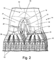
- FIG. 2 is a partially cut-away isometric view of second header 14 of heat exchanger 10 showing a more detailed view of the integrated horns (e.g., primary horn 18 and secondary horns 20) and sacrificial support structure 22.
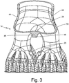
- FIG. 3 is partially cut-away isometric view of second header 14 showing varying wall thickness.
- Second header 14 includes primary horn 18, secondary horns 20, and sacrificial support structure 22 (not shown in FIG. 3 ).
- Sacrificial support structure 22 includes trunk 24 and limbs 26.
- Second header 14 additionally includes overhang region 28 of primary fluid duct 30, first branched region 32, secondary fluid ducts 34, second branched regions 36, tertiary fluid ducts 38, third branched regions 40, and quaternary fluid ducts 42.
- second header 14 is defined by thin walls 44, thick walls 46, interior surface 48, and exterior surface 50.
- Primary fluid duct 30 forms a first section of second header 14. Primary fluid duct 30 extends between second fluid port 15 ( FIG. 1 ) and first branched region 32. First branched region 32 forms an end of primary fluid duct 30 distal to second fluid port 15.
- Secondary fluid ducts 34 are fluidly connected to primary fluid duct 30 at first branched region 32. Though the examples of FIGS. 2 and 3 show first branched region 32 branching into four secondary fluid ducts 34, it should be understood that in other examples, alternate configurations are possible, including more or fewer secondary fluid ducts 34 extending from first branched region 32.
- Each secondary fluid duct 34 extends between first branched region 32 and second branched regions 36. Each secondary fluid duct 34 can form a relatively straight path between first branched region 32 and second branched regions 36. At second branched regions 36, each secondary fluid duct is fluidly connected to tertiary fluid ducts 38. Though the examples of FIGS. 2 and 3 show second branched regions 36 branching into sixteen tertiary fluid ducts 38, it should be understood that in other examples, alternate configurations are possible, including more or fewer tertiary fluid ducts 38 extending from each second branched region 36.
- second header 14 can have a fractal geometry defining the branching relationship between secondary fluid ducts 34 and tertiary fluid ducts 38, such that the number of tertiary fluid ducts 38 extending from each second branched region 36 is equal to the total number of secondary fluid ducts 34. In yet other examples, the number of tertiary fluid ducts 38 extending from different second branched regions 36 can be varied throughout second header 14.
- Third branched regions 40 form ends of tertiary fluid ducts 38 distal to second branched regions 36.
- Quaternary fluid ducts 42 are fluidly connected to tertiary fluid ducts 38 at third branched regions 40.
- Each quaternary fluid duct 42 extends between one of third branched regions 40 and core 16 ( FIG. 1 ).
- Each quaternary fluid duct 42 can form a relatively straight path between third branched regions 40 and core 16.
- each of quaternary fluid ducts 42 can form an individual connection with a tube of core 16 (not shown). Though the examples of FIGS.
- second header 14 can have a fractal geometry defining the branching relationship between tertiary fluid ducts 38 and quaternary fluid ducts 42, such that the number of quaternary fluid ducts 42 extending from each third branched region 40 is equal to the total number of tertiary fluid ducts 38.
- the number of quaternary fluid ducts 42 extending from different third branched regions 40 can be varied throughout second header 14, or there can be additional levels of branching between third branched regions 40 and core 16.
- Overhang region 28 defines the structural region of second header 14 that spans centrally between adjacent ones of secondary fluid ducts 34. Secondary fluid ducts 34 are separated such that an open space is formed within the branching structure of second header 14.
- Primary horn 18 is integrally formed with and extends from overhang region 28 into the open space.
- At least one secondary horn 20 can be integrally formed with and extend from at least one of tertiary fluid ducts 38 into the open space.
- a single secondary horn 20 extends from a single tertiary fluid duct 38 per each of the four second branched regions 36, such that there are four secondary horns 20.
- the particular tertiary fluid duct 38 from which one secondary horn 20 extends can be one of tertiary fluid ducts 38 that is disposed along the central open space formed within second header 14. It should also be understood that in other examples, alternate configurations are possible, including more or fewer secondary horns 20 extending from individual tertiary fluid ducts 38.
- primary horn 18 has a generally columnar shape.
- Primary horn 18 connects to trunk 24 of sacrificial support structure 22. Trunk 24 branches into limbs 26.
- Each of limbs 26 of sacrificial support structure 22 connects to one of secondary horns 20, such that the number of limbs 26 can be equal to the number of secondary horns 20.
- the entirety of sacrificial support structure 22 can be situated within the open space formed within the branching structure of second header 14.
- the tubular structures of second header 14 are formed of thin walls 44.
- Interior surface 48 defines an interior cavity of second header 14.
- Exterior surface 50 defines an exterior of second header 14. The distance between interior surface 48 and exterior surface 50 can be relatively small (e.g., one tenth of a millimeter, a millimeter, or other distances) along thin walls 44 because the overall three-dimensional structure of second header 14 is hollow (i.e., tubular) in these regions.
- Primary horn 18 and secondary horns 20, by contrast, are defined by thick walls 46.
- the three-dimensional structure of primary horn 18 is not tubular or hollow but instead is solid. Therefore, the distance between interior surface 48 and exterior surface 50 can be greater at thick walls 46 than the distance between interior surface 48 and exterior surface 50 at thin walls 44. In other words, thick walls 46 can have a greater width than thin walls 44.
- first fluid F 1 entering second header 14 at second fluid port 15 is channeled through primary fluid duct 30 to first branched region 32.
- first fluid F 1 flows into secondary fluid ducts 34.
- First fluid F 1 flows within secondary fluid ducts 34 to reach second branched regions 36.
- first fluid F 1 is channeled out from one secondary fluid duct 34 and into tertiary fluid ducts 38.
- First fluid F 1 flows within tertiary fluid ducts 38 to reach third branched regions 40.
- first fluid F 1 is channeled out from one tertiary fluid duct 38 and into quaternary fluid ducts 42.
- first fluid F 1 flows directly from quaternary fluid ducts 42 into core 16 ( FIG. 1 ).
- second header 14 can be configured to include additional levels of branching and intervening fluid ducts fluidly connected downstream of quaternary fluid ducts 42 and upstream of core 16. Heat transfer between first fluid F 1 and the second fluid (not shown) can occur largely at core 16 of heat exchanger 10.
- Primary horn 18 and secondary horns 20 extend away from overhang region 28 and tertiary fluid ducts 38, respectively, such that sacrificial support structure 22 is not connected directly to any of thin walls 44.
- thick walls 46 e.g., at primary horn 18 and secondary horns 20 serve as regions where sacrificial support structure 22 can be machined away or even broken away (i.e., sacrificial support structure 22 can be machinable or frangible) from the remaining structure of heat exchanger 10.
- sacrificial support structure 22 can be machined away from heat exchanger 10 in a single post-manufacture machining process. Integrated supports to be left in place during operation of a heat exchanger are not desirable because these impart large stress concentrations due to high thermal growth during operation of the heat exchanger. A permanent connection between parts of a heat exchanger would prevent the heat exchanger from expanding (e.g., thermal expansion caused by contact with hot first fluid F 1 ), resulting in increased stress concentrations.
- a heat exchanger manufactured with sacrificial supports that are connected directly to the structure of the heat exchanger is not desirable because removing the sacrificial support could cause damage to the relatively fragile heat exchanger structure.
- the solid structure and thick walls 46 of primary horn 18 and secondary horns 20 to which sacrificial support structure 22 is connected prevent damage to thin walls 44 because any machining or breakage to remove sacrificial support structure 22 will occur at thick walls 46 rather than thin walls 44.
- thick walls 46 can serve as a buffer between the relatively fragile structure of heat exchanger 10 and any disturbances caused by post-manufacture machining or breakaway processes.
- sacrificial support structure 22 can be machined away in single post-manufacture process that cuts through each of its connections to primary horn 18 and secondary horns 20 (e.g., at trunk 24 and limbs 26) in sequence.
- heat exchanger 10 Because sacrificial support structure 22-which forms a connection between overhang region 28 and tertiary fluid ducts 38 of second header 14 and would prevent expansion of heat exchanger 10 during operation-can be removed prior to operation of heat exchanger 10, the remaining unconnected primary horn 18 and secondary horns 20 do not impart significant stress concentrations. Accordingly, the techniques of this disclosure allow for heat exchanger 10 to have increased efficiency and to be manufactured more effectively compared to traditional heat exchanger configurations.
- a heat exchanger header includes a primary fluid duct extending between a fluid port and a first branched region, a plurality of secondary fluid ducts fluidly connected to the primary fluid duct at the first branched region, wherein the plurality of secondary fluid ducts extends from the first branched region such that an overhang region is formed laterally between adjacent ones of the plurality of secondary fluid ducts, and wherein each of the plurality of secondary fluid ducts extends between the first branched region and a second branched region, a plurality of tertiary fluid ducts fluidly connected to each of the plurality of secondary fluid ducts at the second branched regions, a primary horn integrally formed with and extending from the overhang region, an at least one secondary horn integrally formed with and extending from one of the plurality of tertiary fluid ducts, and a sacrificial support structure extending between the primary horn and the at least one secondary horn.
- the heat exchanger header of the preceding paragraph can optionally include, additionally and/or alternatively, any one or more of the following features, configurations and/or additional components:
- the primary, secondary, and tertiary fluid ducts can be tubular.
- the header can have a fractal geometry.
- the header can be configured to receive or discharge a first fluid and to interact with a second fluid in a counterflow arrangement.
- the primary and secondary horns can be arranged such that all of the primary and secondary horns are visible from an at least one same line of sight through the header.
- the header can be configured to be additively manufactured as a single, monolithic unit.
- the header can be formed from a metallic material.
- the sacrificial support structure can be configured to be removed from the primary and secondary horns during a single wire-electrical discharge machining (wire-EDM) process.
- wire-EDM wire-electrical discharge machining
- the heat exchanger header can further include a core, wherein the header is fluidly connected to the core distal to the fluid port.
- a heat exchanger includes a first header, a second header, and a core extending between the first header and the second header such that the first header, the second header, and the core are fluidly connected.
- the second header includes a primary fluid duct extending between a fluid port and a first branched region, a plurality of secondary fluid ducts fluidly connected to the primary fluid duct at the first branched region, wherein the plurality of secondary fluid ducts extends from the first branched region such that an overhang region is formed laterally between adjacent ones of the plurality of secondary fluid ducts, and wherein each of the plurality of secondary fluid ducts extends between the first branched region and a second branched region, a plurality of tertiary fluid ducts fluidly connected to each of the plurality of secondary fluid ducts at the second branched regions, a primary horn integrally formed with and extending from the overhang region, an at least one secondary horn integrally formed with and extending from one of the plurality of
- the heat exchanger of the preceding paragraph can optionally include, additionally and/or alternatively, any one or more of the following features, configurations and/or additional components:
- the primary, secondary, and tertiary fluid ducts can be tubular.
- the first and second headers can have a fractal geometry.
- the heat exchanger can be configured to receive or discharge a first fluid and to interact with a second fluid in a counterflow arrangement.
- the primary and secondary horns can be arranged such that all of the primary and secondary horns are visible from an at least one same line of sight through the second header.
- the heat exchanger can be formed from a metallic material.
- the sacrificial support structure can be configured to be removed from the primary and secondary horns during a single wire-electrical discharge machining (wire-EDM) process.
- wire-EDM wire-electrical discharge machining
- a method can include constructing the heat exchanger utilizing an additive manufacturing process, wherein the heat exchanger is configured to be additively manufactured as a single, monolithic unit.
- the heat exchanger can be oriented such that the second header is an uppermost header during the additive manufacturing process and the overhang region is substantially parallel to a horizontal build plane.
- the additive manufacturing process can be a laser-powder bed fusion (L-PBF) process.
- L-PBF laser-powder bed fusion
- the method can further include removing at least a portion of the sacrificial support structure after the additive manufacturing process is completed utilizing a wire-electrical discharge machining (wire-EDM) process.
- wire-EDM wire-electrical discharge machining
Abstract
Description
- This disclosure relates generally to heat exchangers, and more specifically to support structures for heat exchanger headers.
- Heat exchangers are well known in many industries for providing compact, low-weight, and highly-effective means of exchanging heat from a hot fluid to a cold fluid. Heat exchangers can operate in high temperature environments, such as in modern aircraft engines. Heat exchangers that operate at elevated temperatures can have reduced service lives due to high thermal stress. Thermal stresses can be caused by uneven temperature distribution within the heat exchanger or with abutting components, component stiffness and geometry discontinuity, and/or other material properties of the heat exchanger. The interface between inlet or outlet headers and the core of a heat exchanger can be subject to the highest thermal stress and shortest service life.
- Additive manufacturing techniques can be utilized to manufacture heat exchangers layer by layer to obtain a variety of complex geometries. Depending on the geometry of the heat exchanger, additional internal or external support structures can be necessary during additive manufacturing to reinforce a build or to facilitate the manufacturing process (e.g., act as heat sinks to stabilize the melt pool of a weld). Often, removal of internal support structures from a heat exchanger is difficult or even impossible, thereby limiting the geometries that can be built successfully. Furthermore, support structures can be sources of increased thermal stress when the support structures remain intact during operation of the heat exchanger.
- In one example, a heat exchanger header includes a primary fluid duct extending between a fluid port and a first branched region, a plurality of secondary fluid ducts fluidly connected to the primary fluid duct at the first branched region, wherein the plurality of secondary fluid ducts extends from the first branched region such that an overhang region is formed laterally between adjacent ones of the plurality of secondary fluid ducts, and wherein each of the plurality of secondary fluid ducts extends between the first branched region and a second branched region, a plurality of tertiary fluid ducts fluidly connected to each of the plurality of secondary fluid ducts at the second branched regions, a primary horn integrally formed with and extending from the overhang region, an at least one secondary horn integrally formed with and extending from one of the plurality of tertiary fluid ducts, and a sacrificial support structure extending between the primary horn and the at least one secondary horn.
- In another example, a heat exchanger includes a first header, a second header, and a core extending between the first header and the second header such that the first header, the second header, and the core are fluidly connected. The second header includes a primary fluid duct extending between a fluid port and a first branched region, a plurality of secondary fluid ducts fluidly connected to the primary fluid duct at the first branched region, wherein the plurality of secondary fluid ducts extends from the first branched region such that an overhang region is formed laterally between adjacent ones of the plurality of secondary fluid ducts, and wherein each of the plurality of secondary fluid ducts extends between the first branched region and a second branched region, a plurality of tertiary fluid ducts fluidly connected to each of the plurality of secondary fluid ducts at the second branched regions, a primary horn integrally formed with and extending from the overhang region, an at least one secondary horn integrally formed with and extending from one of the plurality of tertiary fluid ducts, and a sacrificial support structure extending between the primary horn and the at least one secondary horn.
-
-
FIG. 1 is a side view of a heat exchanger in a vertical orientation showing a first header, a second header, and a core. -
FIG. 2 is an isometric view of a heat exchanger header showing integrated horns and a sacrificial support structure. -
FIG. 3 is partially cut-away isometric view of a heat exchanger header showing varying wall thickness. - A heat exchanger with integrated horns and a sacrificial support structure is disclosed herein. The combination of the integrated horns and the sacrificial support structure enables the heat exchanger not only to be additively manufactured in the nearly vertical orientation that is required due to other manufacturing constraints, but also to meet operational performance requirements without damaging the part by inducing thermal stresses in the supported regions. In general, the heat exchanger is formed of a system of fluid ducts. (The term "duct" as used herein refers to a walled structure enclosing a channel or passageway for fluid flow.) The heat exchanger is described below with reference to
FIGS. 1-3 . -
FIG. 1 is a side view ofheat exchanger 10 in a vertical orientation.Heat exchanger 10 includesfirst header 12 withfirst fluid port 13,second header 14 withsecond fluid port 15, andcore 16.Second header 14 includesprimary horn 18,secondary horns 20, andsacrificial support structure 22.Heat exchanger 10 interacts with first fluid F1 and a second fluid (not shown). -
First fluid port 13 forms an opening into the fluid system ofheat exchanger 10. Specifically,first fluid port 13 opens intofirst header 12.First header 12 is fluidly connected tocore 16 distal tofirst fluid port 13.Second fluid port 15 forms an additional opening into the fluid system ofheat exchanger 10 oppositefirst fluid port 13.Second fluid port 15 opens intosecond header 14.Second header 14 is fluidly connected tocore 16 distal tosecond fluid port 15.First header 12 andsecond header 14 can have substantially similar branching structures or other overall geometries. - Core 16 is disposed between
first header 12 andsecond header 14. As shown inFIG. 1 , the three-dimensional structure ofcore 16 can be slightly curved, but it should be understood that alternative embodiments can include other core types and/or geometries, including larger or shallower curved regions or separations between core layers to form branched paths withincore 16. In the example ofFIG. 1 ,first header 12,core 16, andsecond header 14 are also shown to be oriented substantially in a straight line along an axis that extends perpendicularly from horizontal plane H (horizontal plane H is utilized herein as a representative plane that is parallel to sides ofheat exchanger 10 corresponding tofirst fluid port 13 and second fluid port 15). - Though the example of
FIG. 1 illustratesheat exchanger 10 as including a singlefirst header 12 and asingle second header 14 connected tocore 16, it should be understood that in other examples,heat exchanger 10 can include more than two header structures interfacing withcore 16. Multiple header structures can be arranged in a substantially similar manner tofirst header 12 andsecond header 14 and can form additional layers of an interface withcore 16.First header 12 andsecond header 14 can be configured to connect tocore 16 such thatfirst header 12 andsecond header 14 are coplanar. However, it should be understood that other embodiments can includefirst header 12 and second header 14 (and additional headers not shown inFIG. 1 ) oriented along different planes with respect to each other. -
Primary horn 18 is integrally formed withsecond header 14, as is further described below.Primary horn 18 extends centrally fromsecond header 14 and has a generally columnar shape. Based on the orientation ofsecond header 14 with respect to horizontal plane H,primary horn 18 can be perpendicular or approximately perpendicular to horizontal plane H.Secondary horns 20 are integrally formed with and extend fromsecond header 14 at locations distal toprimary horn 18, as is further described below.Secondary horns 20 are shaped similarly toprimary horn 18 and also have generally columnar structures.Sacrificial support structure 22 connectsprimary horn 18 to each ofsecondary horns 20.Sacrificial support structure 22 can be integrally formed with each ofprimary horn 18 andsecondary horns 20. Though the example ofFIG. 1 shows a singleprimary horn 18 extending fromsecond header 14, it should be understood that other examples can include additionalprimary horns 18 extending in a substantially similar manner fromsecond header 14 and forming additional connections tosacrificial support structure 22. - During operation,
heat exchanger 10 is configured to permit the transfer of heat between first fluid F1 and the second fluid (not shown). For example, a transfer of heat can be associated with the use of first fluid F1 and/or the second fluid for cooling and/or lubrication of components in a larger system, such as a gas turbine engine or aerospace system. First fluid F1 and the second fluid can be any type of fluid, including air, water, lubricant, fuel, or another fluid.Heat exchanger 10 is described herein as providing heat transfer from first fluid F1 to the second fluid; therefore, first fluid F1 is at a greater temperature than the second fluid at the point where first fluid F1 enters heat exchanger 10 (i.e., first fluid F1 is a "hot" fluid and the second fluid is a "cold" fluid). However, other configurations ofheat exchanger 10 can include the second fluid at a greater temperature than first fluid F1 (and, thus, the second fluid would be the "hot" fluid and first fluid F1 would be the "cold" fluid). - In the example of
FIG. 1 , first fluid F1 is shown enteringheat exchanger 10 atsecond fluid port 15. In another example, the direction of flow of first fluid F1 can be reversed such that first fluid F1exits heat exchanger 10 at second fluid port 15 (and instead entersheat exchanger 10 at first fluid port 13). Thus,first fluid port 13 andsecond fluid port 15 can be configured alternately to receive or discharge first fluid F1 (i.e.,first header 12 andsecond header 14 can be configured alternately as inlet or outlet headers). Furthermore,heat exchanger 10 can be arranged to receive the second fluid atcore 16 externally toheat exchanger 10 and in an opposite flow direction compared to first fluid F1 (i.e., a counter-flow arrangement). The path of first fluid F1 withinheat exchanger 10 will be discussed in greater detail below with respect toFIGS. 2 and3 . - Heat exchanger 10 (and/or any component parts, including
first header 12,second header 14, and core 16) can be formed partially or entirely by additive manufacturing. For metal components (e.g., nickel-based superalloys, aluminum, titanium, etc.) exemplary additive manufacturing processes include laser-powder bed fusion (L-PBF) techniques such as direct metal laser sintering (DMLS), laser net shape manufacturing (LNSM), electron beam manufacturing (EBM), to name a few, non-limiting examples. For polymer or plastic components, stereolithography (SLA) can be used. Additive manufacturing is particularly useful in obtaining unique geometries and for reducing the need for welds or other attachments (e.g., between a header and core). However, it should be understood that other suitable manufacturing processes can be used. - During an additive manufacturing process, heat exchanger 10 (and/or any component parts, including
first header 12,second header 14, and core 16) can be formed layer by layer to achieve varied tubular dimensions (e.g., cross-sectional area, wall thicknesses, curvature, etc.). Each additively manufactured layer creates a new horizontal build plane (e.g., parallel to horizontal plane H) to which a subsequent layer ofheat exchanger 10 is fused. That is, the build plane for the additive manufacturing process remains horizontal but shifts vertically by defined increments (e.g., one micrometer, one hundredth of a millimeter, one tenth of a millimeter, a millimeter, or other distances) as manufacturing proceeds. The example ofFIG. 1 showsheat exchanger 10 already fully manufactured. Due to geometrical constraints,heat exchanger 10 is additively manufactured in the near vertical orientation, with respect to horizontal plane H, which is depicted inFIG. 1 . -
Primary horn 18 andsecondary horns 20 are additively manufactured along withheat exchanger 10 such that each ofprimary horn 18 andsecondary horns 20 is integrally formed with the walls ofsecond header 14. During an additive manufacturing process,primary horn 18 andsecondary horns 20, in conjunction withsacrificial support structure 22, function to support overhanging regions (e.g.,overhang region 28 as shown inFIGS. 2 and3 ) of the structure ofsecond header 14. - Once
heat exchanger 10 has been manufactured,primary horn 18 andsecondary horns 20 remain as part of the structure ofheat exchanger 10 during operation.Sacrificial support structure 22 is configured to be removed fromheat exchanger 10 during a post-manufacture machining process, such as wire-electrical discharge machining (wire-EDM) or milling. Thus, it is critical to the operation of the component thatsacrificial support structure 22 does not remain as part of the structure ofheat exchanger 10 during operation. - In general, the branching structure of
heat exchanger 10 retains the benefits of fractal geometry compared to traditional heat exchanger header configurations. Traditional heat exchanger headers, such as those with box-shaped manifolds, can have increased stress concentration at the interface between the manifold and the core, particularly at corners of the manifold where there is geometry discontinuity. The branching pattern of fractal heat exchanger headers, wherein each fluid duct is individually and directly connected to a passage in the core, as shown inFIG. 1 , can reduce this geometry discontinuity. Furthermore, each fluid duct in a fractal heat exchanger header (e.g.,first header 12 and second header 14) behaves like a slim beam with low stiffness in transverse directions and reduced stiffness in horizontal directions due to the curved shape at each branched region. Thus,first header 12 andsecond header 14 have increased compliance (i.e., reduced stiffness) and experience less thermal stress compared to traditional heat exchanger header configurations. - Furthermore, the addition of
primary horn 18,secondary horns 20, andsacrificial support structure 22 enablesheat exchanger 10 to be manufactured in the near vertical orientation that is required for powder bed fusion techniques of additive manufacturing. During a powder bed fusion process, it is ideal to print (i.e., weld or sinter) a new layer of an object directly on top of a previously printed layer, so that the previously printed layer can serve as a heat sink during printing of the new layer. - In any orientation,
heat exchanger 10 can have overhanging regions (e.g.,overhang region 28 between secondaryfluid ducts 34 ofsecond header 14 as shown inFIGS. 2 and3 ), which are not-by themselves-adequately supported by a previously printed layer ofheat exchanger 10. Designing the branching regions of a heat exchanger header to instead have a sharper intersection (which can be visualized simplistically as an upside-down "V") would change the construction so that subsequent layers would be built on top of a previous layer, but would also introduce high stress concentration at the sharp corner during operation of the heat exchanger. As such, it is beneficial to use a larger radius blend (which can be visualized simplistically as an upside-down "U," as illustrated inFIGS. 2 and3 by overhang region 28), though this results in the less-printable overhang regions described above. Building these overhang regions can be difficult and costly because such a build would require very tight control over laser process parameters (e.g., with closed-loop feedback mechanisms or other process monitoring techniques). - The addition of
primary horn 18,secondary horns 20, andsacrificial support structure 22 resolves these issues of printability and process efficiency associated with the additive manufacturing ofheat exchanger 10. Becauseprimary horn 18 extends approximately vertically from a central region of second header 14 (e.g.,overhang region 28 inFIGS. 2 and3 ) in the orientation for manufacturing illustrated inFIG. 1 , there is no longer a significant overhanging region ofsecond header 14 that is unsupported by previously manufactured layers. In other words, whenheat exchanger 10 is additively manufactured in the direction fromfirst header 12 tosecond header 14, the combination ofprimary horn 18,secondary horns 20, andsacrificial support structure 22 is manufactured layer-by-layer along with the rest ofheat exchanger 10 such that a final layer printed in the region corresponding toprimary horn 18 will be directly underlying a first layer printed in the otherwise overhanging region of second header 14 (e.g.,overhang region 28 inFIGS. 2 and3 ). The connection ofprimary horn 18 tosecondary horns 20 viasacrificial support structure 22 provides similar support during additive manufacturing forprimary horn 18. - Thus,
heat exchanger 10 can be additively manufactured as a single, monolithic unit. Accordingly, the techniques of this disclosure allow forheat exchanger 10 to have increased efficiency and to be manufactured more effectively compared to traditional heat exchanger configurations. - For purposes of clarity and ease of discussion,
FIGS. 2 and3 will be described together.FIG. 2 is a partially cut-away isometric view ofsecond header 14 ofheat exchanger 10 showing a more detailed view of the integrated horns (e.g.,primary horn 18 and secondary horns 20) andsacrificial support structure 22.FIG. 3 is partially cut-away isometric view ofsecond header 14 showing varying wall thickness. -
Second header 14 includesprimary horn 18,secondary horns 20, and sacrificial support structure 22 (not shown inFIG. 3 ).Sacrificial support structure 22 includestrunk 24 andlimbs 26.Second header 14 additionally includesoverhang region 28 ofprimary fluid duct 30, first branchedregion 32,secondary fluid ducts 34, second branchedregions 36, tertiary fluid ducts 38, thirdbranched regions 40, andquaternary fluid ducts 42. As shown inFIG. 3 ,second header 14 is defined bythin walls 44,thick walls 46,interior surface 48, andexterior surface 50. -
Primary fluid duct 30 forms a first section ofsecond header 14.Primary fluid duct 30 extends between second fluid port 15 (FIG. 1 ) and firstbranched region 32. First branchedregion 32 forms an end ofprimary fluid duct 30 distal to secondfluid port 15. -
Secondary fluid ducts 34 are fluidly connected toprimary fluid duct 30 at firstbranched region 32. Though the examples ofFIGS. 2 and3 show first branchedregion 32 branching into foursecondary fluid ducts 34, it should be understood that in other examples, alternate configurations are possible, including more or fewersecondary fluid ducts 34 extending from firstbranched region 32. - Each
secondary fluid duct 34 extends between firstbranched region 32 and secondbranched regions 36. Eachsecondary fluid duct 34 can form a relatively straight path between firstbranched region 32 and secondbranched regions 36. At secondbranched regions 36, each secondary fluid duct is fluidly connected to tertiary fluid ducts 38. Though the examples ofFIGS. 2 and3 show second branchedregions 36 branching into sixteen tertiary fluid ducts 38, it should be understood that in other examples, alternate configurations are possible, including more or fewer tertiary fluid ducts 38 extending from each secondbranched region 36. In some examples,second header 14 can have a fractal geometry defining the branching relationship between secondaryfluid ducts 34 and tertiary fluid ducts 38, such that the number of tertiary fluid ducts 38 extending from each secondbranched region 36 is equal to the total number ofsecondary fluid ducts 34. In yet other examples, the number of tertiary fluid ducts 38 extending from different secondbranched regions 36 can be varied throughoutsecond header 14. - Third branched
regions 40 form ends of tertiary fluid ducts 38 distal to secondbranched regions 36.Quaternary fluid ducts 42 are fluidly connected to tertiary fluid ducts 38 at thirdbranched regions 40. Eachquaternary fluid duct 42 extends between one of thirdbranched regions 40 and core 16 (FIG. 1 ). Eachquaternary fluid duct 42 can form a relatively straight path between thirdbranched regions 40 andcore 16. Additionally, each ofquaternary fluid ducts 42 can form an individual connection with a tube of core 16 (not shown). Though the examples ofFIGS. 2 and3 show third branchedregions 40 branching into fourquaternary fluid ducts 42, it should be understood that in other examples, alternate configurations are possible, including more or fewerquaternary fluid ducts 42 extending from thirdbranched regions 40. In some examples,second header 14 can have a fractal geometry defining the branching relationship between tertiary fluid ducts 38 andquaternary fluid ducts 42, such that the number ofquaternary fluid ducts 42 extending from each thirdbranched region 40 is equal to the total number of tertiary fluid ducts 38. In yet other examples, the number ofquaternary fluid ducts 42 extending from different thirdbranched regions 40 can be varied throughoutsecond header 14, or there can be additional levels of branching between thirdbranched regions 40 andcore 16. -
Overhang region 28 defines the structural region ofsecond header 14 that spans centrally between adjacent ones ofsecondary fluid ducts 34.Secondary fluid ducts 34 are separated such that an open space is formed within the branching structure ofsecond header 14.Primary horn 18 is integrally formed with and extends fromoverhang region 28 into the open space. At least onesecondary horn 20 can be integrally formed with and extend from at least one of tertiary fluid ducts 38 into the open space. In the example ofFIG. 2 , a singlesecondary horn 20 extends from a single tertiary fluid duct 38 per each of the four secondbranched regions 36, such that there are foursecondary horns 20. The particular tertiary fluid duct 38 from which onesecondary horn 20 extends can be one of tertiary fluid ducts 38 that is disposed along the central open space formed withinsecond header 14. It should also be understood that in other examples, alternate configurations are possible, including more or fewersecondary horns 20 extending from individual tertiary fluid ducts 38. - As described above with respect to
FIG. 1 ,primary horn 18 has a generally columnar shape.Primary horn 18 connects totrunk 24 ofsacrificial support structure 22.Trunk 24 branches intolimbs 26. Each oflimbs 26 ofsacrificial support structure 22 connects to one ofsecondary horns 20, such that the number oflimbs 26 can be equal to the number ofsecondary horns 20. In the example ofFIG. 2 , there are foursecondary horns 20, sotrunk 24 branches into four correspondinglimbs 26. The entirety ofsacrificial support structure 22 can be situated within the open space formed within the branching structure ofsecond header 14. - As is best shown in
FIG. 3 , the tubular structures of second header 14 (e.g.,primary fluid duct 30,secondary fluid ducts 34, tertiary fluid ducts 38, andquaternary fluid ducts 42 as shown inFIG. 2 ) are formed ofthin walls 44.Interior surface 48 defines an interior cavity ofsecond header 14.Exterior surface 50 defines an exterior ofsecond header 14. The distance betweeninterior surface 48 andexterior surface 50 can be relatively small (e.g., one tenth of a millimeter, a millimeter, or other distances) alongthin walls 44 because the overall three-dimensional structure ofsecond header 14 is hollow (i.e., tubular) in these regions. -
Primary horn 18 andsecondary horns 20, by contrast, are defined bythick walls 46. As shown in the example ofFIG. 3 , the three-dimensional structure ofprimary horn 18 is not tubular or hollow but instead is solid. Therefore, the distance betweeninterior surface 48 andexterior surface 50 can be greater atthick walls 46 than the distance betweeninterior surface 48 andexterior surface 50 atthin walls 44. In other words,thick walls 46 can have a greater width thanthin walls 44. - With continued reference to
FIGS. 2 and3 , first fluid F1 enteringsecond header 14 at second fluid port 15 (FIG. 1 ) is channeled throughprimary fluid duct 30 to firstbranched region 32. At firstbranched region 32, first fluid F1 flows intosecondary fluid ducts 34. First fluid F1 flows withinsecondary fluid ducts 34 to reach secondbranched regions 36. At each secondbranched region 36, first fluid F1 is channeled out from onesecondary fluid duct 34 and into tertiary fluid ducts 38. First fluid F1 flows within tertiary fluid ducts 38 to reach thirdbranched regions 40. At each thirdbranched region 40, first fluid F1 is channeled out from one tertiary fluid duct 38 and intoquaternary fluid ducts 42. - In the examples of
FIGS. 2 and3 , first fluid F1 flows directly fromquaternary fluid ducts 42 into core 16 (FIG. 1 ). In alternative embodiments,second header 14 can be configured to include additional levels of branching and intervening fluid ducts fluidly connected downstream ofquaternary fluid ducts 42 and upstream ofcore 16. Heat transfer between first fluid F1 and the second fluid (not shown) can occur largely atcore 16 ofheat exchanger 10. -
Primary horn 18 andsecondary horns 20 extend away fromoverhang region 28 and tertiary fluid ducts 38, respectively, such thatsacrificial support structure 22 is not connected directly to any ofthin walls 44. Thus, thick walls 46 (e.g., atprimary horn 18 and secondary horns 20) serve as regions wheresacrificial support structure 22 can be machined away or even broken away (i.e.,sacrificial support structure 22 can be machinable or frangible) from the remaining structure ofheat exchanger 10. - In addition to the benefits of
heat exchanger 10 as described above with reference toFIG. 1 ,sacrificial support structure 22 can be machined away fromheat exchanger 10 in a single post-manufacture machining process. Integrated supports to be left in place during operation of a heat exchanger are not desirable because these impart large stress concentrations due to high thermal growth during operation of the heat exchanger. A permanent connection between parts of a heat exchanger would prevent the heat exchanger from expanding (e.g., thermal expansion caused by contact with hot first fluid F1), resulting in increased stress concentrations. Furthermore, a heat exchanger manufactured with sacrificial supports that are connected directly to the structure of the heat exchanger (e.g., ifsacrificial support structure 22 was instead connected directly to thin walls 44) is not desirable because removing the sacrificial support could cause damage to the relatively fragile heat exchanger structure. - The solid structure and
thick walls 46 ofprimary horn 18 andsecondary horns 20 to whichsacrificial support structure 22 is connected prevent damage tothin walls 44 because any machining or breakage to removesacrificial support structure 22 will occur atthick walls 46 rather thanthin walls 44. Thus,thick walls 46 can serve as a buffer between the relatively fragile structure ofheat exchanger 10 and any disturbances caused by post-manufacture machining or breakaway processes. - Furthermore, because
primary horn 18,secondary horns 20, andsacrificial support structure 22 all extend into the same open space withinsecond header 14 such that all are visible from one line of sight throughheat exchanger 10, the connections oftrunk 24 andlimbs 26 ofsacrificial support structure 22 are easily accessible by any machining equipment which may be used, such as in a wire-electrical discharge machining (wire-EDM) process. Thus, rather than requiring multiple steps,sacrificial support structure 22 can be machined away in single post-manufacture process that cuts through each of its connections toprimary horn 18 and secondary horns 20 (e.g., attrunk 24 and limbs 26) in sequence. - Because sacrificial support structure 22-which forms a connection between
overhang region 28 and tertiary fluid ducts 38 ofsecond header 14 and would prevent expansion ofheat exchanger 10 during operation-can be removed prior to operation ofheat exchanger 10, the remaining unconnectedprimary horn 18 andsecondary horns 20 do not impart significant stress concentrations. Accordingly, the techniques of this disclosure allow forheat exchanger 10 to have increased efficiency and to be manufactured more effectively compared to traditional heat exchanger configurations. - The following are non-exclusive descriptions of possible embodiments of the present invention.
- A heat exchanger header includes a primary fluid duct extending between a fluid port and a first branched region, a plurality of secondary fluid ducts fluidly connected to the primary fluid duct at the first branched region, wherein the plurality of secondary fluid ducts extends from the first branched region such that an overhang region is formed laterally between adjacent ones of the plurality of secondary fluid ducts, and wherein each of the plurality of secondary fluid ducts extends between the first branched region and a second branched region, a plurality of tertiary fluid ducts fluidly connected to each of the plurality of secondary fluid ducts at the second branched regions, a primary horn integrally formed with and extending from the overhang region, an at least one secondary horn integrally formed with and extending from one of the plurality of tertiary fluid ducts, and a sacrificial support structure extending between the primary horn and the at least one secondary horn.
- The heat exchanger header of the preceding paragraph can optionally include, additionally and/or alternatively, any one or more of the following features, configurations and/or additional components:
The primary, secondary, and tertiary fluid ducts can be tubular. - The header can have a fractal geometry.
- The header can be configured to receive or discharge a first fluid and to interact with a second fluid in a counterflow arrangement.
- The primary and secondary horns can be arranged such that all of the primary and secondary horns are visible from an at least one same line of sight through the header.
- The header can be configured to be additively manufactured as a single, monolithic unit.
- The header can be formed from a metallic material.
- The sacrificial support structure can be configured to be removed from the primary and secondary horns during a single wire-electrical discharge machining (wire-EDM) process.
- The heat exchanger header can further include a core, wherein the header is fluidly connected to the core distal to the fluid port.
- A heat exchanger includes a first header, a second header, and a core extending between the first header and the second header such that the first header, the second header, and the core are fluidly connected. The second header includes a primary fluid duct extending between a fluid port and a first branched region, a plurality of secondary fluid ducts fluidly connected to the primary fluid duct at the first branched region, wherein the plurality of secondary fluid ducts extends from the first branched region such that an overhang region is formed laterally between adjacent ones of the plurality of secondary fluid ducts, and wherein each of the plurality of secondary fluid ducts extends between the first branched region and a second branched region, a plurality of tertiary fluid ducts fluidly connected to each of the plurality of secondary fluid ducts at the second branched regions, a primary horn integrally formed with and extending from the overhang region, an at least one secondary horn integrally formed with and extending from one of the plurality of tertiary fluid ducts, and a sacrificial support structure extending between the primary horn and the at least one secondary horn.
- The heat exchanger of the preceding paragraph can optionally include, additionally and/or alternatively, any one or more of the following features, configurations and/or additional components:
The primary, secondary, and tertiary fluid ducts can be tubular. - The first and second headers can have a fractal geometry.
- The heat exchanger can be configured to receive or discharge a first fluid and to interact with a second fluid in a counterflow arrangement.
- The primary and secondary horns can be arranged such that all of the primary and secondary horns are visible from an at least one same line of sight through the second header.
- The heat exchanger can be formed from a metallic material.
- The sacrificial support structure can be configured to be removed from the primary and secondary horns during a single wire-electrical discharge machining (wire-EDM) process.
- A method can include constructing the heat exchanger utilizing an additive manufacturing process, wherein the heat exchanger is configured to be additively manufactured as a single, monolithic unit.
- The heat exchanger can be oriented such that the second header is an uppermost header during the additive manufacturing process and the overhang region is substantially parallel to a horizontal build plane.
- The additive manufacturing process can be a laser-powder bed fusion (L-PBF) process.
- The method can further include removing at least a portion of the sacrificial support structure after the additive manufacturing process is completed utilizing a wire-electrical discharge machining (wire-EDM) process.
- While the invention has been described with reference to an exemplary embodiment(s), it will be understood by those skilled in the art that various changes may be made and equivalents may be substituted for elements thereof without departing from the scope of the invention. In addition, many modifications may be made to adapt a particular situation or material to the teachings of the invention without departing from the essential scope thereof. Therefore, it is intended that the invention not be limited to the particular embodiment(s) disclosed, but that the invention will include all embodiments falling within the scope of the appended claims.
Claims (15)
- A heat exchanger header comprising:a primary fluid duct (30) extending between a fluid port (13) and a first branched region (32);a plurality of secondary fluid ducts (34) fluidly connected to the primary fluid duct at the first branched region, wherein the plurality of secondary fluid ducts extends from the first branched region such that an overhang region (28) is formed laterally between adjacent ones of the plurality of secondary fluid ducts, and wherein each of the plurality of secondary fluid ducts extends between the first branched region and a second branched region (36);a plurality of tertiary fluid ducts (38) fluidly connected to each of the plurality of secondary fluid ducts at the second branched regions;a primary horn (18) integrally formed with and extending from the overhang region;an at least one secondary horn (20) integrally formed with and extending from one of the plurality of tertiary fluid ducts; anda sacrificial support structure (22) extending between the primary horn and the at least one secondary horn.
- The heat exchanger header of claim 1,
wherein the primary, secondary, and tertiary fluid ducts are tubular. - The heat exchanger header of claims 1 or 2,
wherein the header has a fractal geometry. - The heat exchanger header of any preceding claim,
wherein the header is configured to receive or discharge a first fluid and to interact with a second fluid in a counterflow arrangement. - The heat exchanger header of any preceding claim,
wherein the primary and secondary horns are arranged such that all of the primary and secondary horns are visible from an at least one same line of sight through the header. - The heat exchanger header of claim 5,
wherein the header is configured to be additively manufactured as a single, monolithic unit; and preferably
wherein the header is formed from a metallic material; and more preferably
wherein the sacrificial support structure is configured to be removed from the primary and secondary horns during a single wire-electrical discharge machining (wire-EDM) process. - The heat exchanger header of any preceding claim, further comprising:a core (16);wherein the header is fluidly connected to the core distal to the fluid port.
- A heat exchanger comprising:a first header (12);a second header (14) comprising the heat exchanger header of claim 1; anda core (16) extending between the first header and the second header such that the first header, the second header, and the core are fluidly connected.
- The heat exchanger of claim 8,
wherein the first and second headers have a fractal geometry. - The heat exchanger of claim 8 or 9,
wherein the heat exchanger is configured to receive or discharge a first fluid and to interact with a second fluid in a counterflow arrangement. - The heat exchanger of any of claims 8-10,
wherein the primary and secondary horns are arranged such that all of the primary and secondary horns are visible from an at least one same line of sight through the second header; and preferably
wherein the heat exchanger is formed from a metallic material; and more preferably
wherein the sacrificial support structure is configured to be removed from the primary and secondary horns during a single wire-electrical discharge machining (wire-EDM) process. - A method comprising:constructing the heat exchanger of claim 8 utilizing an additive manufacturing process;wherein the heat exchanger is configured to be additively manufactured as a single, monolithic unit.
- The method of claim 12,
wherein the heat exchanger is oriented such that the second header is an uppermost header during the additive manufacturing process and the overhang region is substantially parallel to a horizontal build plane. - The method of claim 12 or 13,
wherein the additive manufacturing process is a laser-powder bed fusion (L-PBF) process. - The method of any of claims 12-14, further comprising:
removing at least a portion of the sacrificial support structure after the additive manufacturing process is completed utilizing a wire-electrical discharge machining (wire-EDM) process.
Priority Applications (1)
| Application Number | Priority Date | Filing Date | Title |
|---|---|---|---|
| EP23181540.8A EP4230943A1 (en) | 2019-11-21 | 2020-09-01 | Integrated horn structures for heat exchanger headers |
Applications Claiming Priority (1)
| Application Number | Priority Date | Filing Date | Title |
|---|---|---|---|
| US16/690,975 US11396069B2 (en) | 2019-11-21 | 2019-11-21 | Integrated horn structures for heat exchanger headers |
Related Child Applications (1)
| Application Number | Title | Priority Date | Filing Date |
|---|---|---|---|
| EP23181540.8A Division EP4230943A1 (en) | 2019-11-21 | 2020-09-01 | Integrated horn structures for heat exchanger headers |
Publications (2)
| Publication Number | Publication Date |
|---|---|
| EP3825638A1 true EP3825638A1 (en) | 2021-05-26 |
| EP3825638B1 EP3825638B1 (en) | 2023-07-26 |
Family
ID=72322338
Family Applications (2)
| Application Number | Title | Priority Date | Filing Date |
|---|---|---|---|
| EP23181540.8A Pending EP4230943A1 (en) | 2019-11-21 | 2020-09-01 | Integrated horn structures for heat exchanger headers |
| EP20193812.3A Active EP3825638B1 (en) | 2019-11-21 | 2020-09-01 | Integrated horn structures for heat exchanger headers |
Family Applications Before (1)
| Application Number | Title | Priority Date | Filing Date |
|---|---|---|---|
| EP23181540.8A Pending EP4230943A1 (en) | 2019-11-21 | 2020-09-01 | Integrated horn structures for heat exchanger headers |
Country Status (2)
| Country | Link |
|---|---|
| US (2) | US11396069B2 (en) |
| EP (2) | EP4230943A1 (en) |
Cited By (2)
| Publication number | Priority date | Publication date | Assignee | Title |
|---|---|---|---|---|
| US20220234013A1 (en) * | 2017-04-21 | 2022-07-28 | Commonwealth Scientific And Industrial Research Organisation | Flow distribution system |
| EP4215864A1 (en) * | 2022-01-21 | 2023-07-26 | Raytheon Technologies Corporation | Heat exchanger header structures |
Families Citing this family (3)
| Publication number | Priority date | Publication date | Assignee | Title |
|---|---|---|---|---|
| US20230068512A1 (en) * | 2021-08-31 | 2023-03-02 | Hamilton Sundstrand Corporation | Fractal optimized core shape (addmfg) |
| US11493286B1 (en) * | 2021-10-12 | 2022-11-08 | Hamilton Sundstrand Corporation | Header for high-pressure heat exchanger |
| JP2023170397A (en) * | 2022-05-19 | 2023-12-01 | 三菱重工業株式会社 | Header member, heat exchange unit and method of manufacturing header member |
Citations (3)
| Publication number | Priority date | Publication date | Assignee | Title |
|---|---|---|---|---|
| US20120074051A1 (en) * | 2009-05-29 | 2012-03-29 | Ge Healthcare Bio-Sciences Ab | Fluid distributor unit |
| US20170089643A1 (en) * | 2015-09-25 | 2017-03-30 | Westinghouse Electric Company, Llc. | Heat Exchanger |
| US20190086154A1 (en) * | 2017-09-20 | 2019-03-21 | Additive Rocket Corporation | Additive manufacturing constructs and processes for their manufacture |
Family Cites Families (14)
| Publication number | Priority date | Publication date | Assignee | Title |
|---|---|---|---|---|
| US2471960A (en) * | 1944-08-14 | 1949-05-31 | Houdaille Hershey Corp | Condenser |
| ITVA20010037A1 (en) * | 2001-10-18 | 2003-04-18 | Whirlpool Co | CONDENSERS FOR DOMESTIC REFRIGERATOR CABINETS AND DOMESTIC REFRIGERATOR CABINET EQUIPPED WITH SUCH CONDENSER. |
| US6675881B1 (en) * | 2002-11-07 | 2004-01-13 | Pratt And Whitney Canada Corp. | Heat exchanger with fins formed from slots |
| GB0521826D0 (en) * | 2005-10-26 | 2005-12-07 | Rolls Royce Plc | Wall cooling arrangement |
| US9134072B2 (en) * | 2010-03-15 | 2015-09-15 | The Trustees Of Dartmouth College | Geometry of heat exchanger with high efficiency |
| DE102013207656A1 (en) * | 2013-04-26 | 2014-10-30 | Siemens Aktiengesellschaft | Optimization of a manufacturing process |
| US10226895B2 (en) * | 2013-12-03 | 2019-03-12 | Autodesk, Inc. | Generating support material for three-dimensional printing |
| US10995996B2 (en) | 2014-10-07 | 2021-05-04 | Unison Industries, Llc | Multi-branch furcating flow heat exchanger |
| US9746257B2 (en) | 2015-08-11 | 2017-08-29 | Hamilton Sundstrand Corporation | Heat exchanger and fabrication |
| DE102016210643A1 (en) * | 2016-06-15 | 2017-12-21 | Siemens Aktiengesellschaft | Method, assistance system and 3D printer for the computer-aided design of objects for additive manufacturing |
| US10584922B2 (en) | 2017-02-22 | 2020-03-10 | Hamilton Sundstrand Corporation | Heat exchanges with installation flexibility |
| US10442003B2 (en) | 2017-03-02 | 2019-10-15 | Velo3D, Inc. | Three-dimensional printing of three-dimensional objects |
| WO2018160914A1 (en) * | 2017-03-03 | 2018-09-07 | Dixon Matthew R | Fluid system components with thermal conditioning passages |
| DE102017113485A1 (en) * | 2017-06-20 | 2018-12-20 | Amsis Gmbh | Method for the additive production of at least one component, support structure or element of a support structure, component with the same and installation for carrying out such a method |
-
2019
- 2019-11-21 US US16/690,975 patent/US11396069B2/en active Active
-
2020
- 2020-09-01 EP EP23181540.8A patent/EP4230943A1/en active Pending
- 2020-09-01 EP EP20193812.3A patent/EP3825638B1/en active Active
-
2022
- 2022-07-25 US US17/872,753 patent/US11666994B2/en active Active
Patent Citations (3)
| Publication number | Priority date | Publication date | Assignee | Title |
|---|---|---|---|---|
| US20120074051A1 (en) * | 2009-05-29 | 2012-03-29 | Ge Healthcare Bio-Sciences Ab | Fluid distributor unit |
| US20170089643A1 (en) * | 2015-09-25 | 2017-03-30 | Westinghouse Electric Company, Llc. | Heat Exchanger |
| US20190086154A1 (en) * | 2017-09-20 | 2019-03-21 | Additive Rocket Corporation | Additive manufacturing constructs and processes for their manufacture |
Cited By (3)
| Publication number | Priority date | Publication date | Assignee | Title |
|---|---|---|---|---|
| US20220234013A1 (en) * | 2017-04-21 | 2022-07-28 | Commonwealth Scientific And Industrial Research Organisation | Flow distribution system |
| US11660577B2 (en) * | 2017-04-21 | 2023-05-30 | Commonwealth Scientific And Industrial Research Organisation | Fractal flow distribution system |
| EP4215864A1 (en) * | 2022-01-21 | 2023-07-26 | Raytheon Technologies Corporation | Heat exchanger header structures |
Also Published As
| Publication number | Publication date |
|---|---|
| US20210154779A1 (en) | 2021-05-27 |
| US11396069B2 (en) | 2022-07-26 |
| US11666994B2 (en) | 2023-06-06 |
| US20220371134A1 (en) | 2022-11-24 |
| EP4230943A1 (en) | 2023-08-23 |
| EP3825638B1 (en) | 2023-07-26 |
Similar Documents
| Publication | Publication Date | Title |
|---|---|---|
| EP3825638A1 (en) | Integrated horn structures for heat exchanger headers | |
| US10583535B2 (en) | Additively manufactured heat exchanger | |
| EP3431911B1 (en) | Additively manufactured heat exchanger | |
| US10184728B2 (en) | Additively manufactured heat exchanger including flow turbulators defining internal fluid passageways | |
| US10801790B2 (en) | Plate fin heat exchanger flexible manifold structure | |
| JP2022036196A (en) | Additively manufactured heat exchanger | |
| US11268770B2 (en) | Heat exchanger with radially converging manifold | |
| US11561048B2 (en) | Circular crossflow heat exchanger | |
| EP3800417A1 (en) | Heat exchanger with interleaved manifolds and layered core | |
| CN112400092B (en) | Heat exchanger having a three-dimensional lattice structure with baffle units and method of forming baffles in a three-dimensional lattice structure of a heat exchanger | |
| US20200016704A1 (en) | Heat Exchangers Having a Three-Dimensional Lattice Structure with a Rounded Unit Cell Entrance and Methods of Forming Rounded Unit Cell Entrances in a Three-Dimensional Lattice Structure of a Heat Exchanger | |
| US20200064076A1 (en) | Hybrid pin-fin-plate heat exchanger | |
| US20200025454A1 (en) | Fin-plate heat exchanger | |
| EP3653984B1 (en) | Plate fin heat exchanger flexible manifold structure |
Legal Events
| Date | Code | Title | Description |
|---|---|---|---|
| PUAI | Public reference made under article 153(3) epc to a published international application that has entered the european phase |
Free format text: ORIGINAL CODE: 0009012 |
|
| STAA | Information on the status of an ep patent application or granted ep patent |
Free format text: STATUS: THE APPLICATION HAS BEEN PUBLISHED |
|
| AK | Designated contracting states |
Kind code of ref document: A1 Designated state(s): AL AT BE BG CH CY CZ DE DK EE ES FI FR GB GR HR HU IE IS IT LI LT LU LV MC MK MT NL NO PL PT RO RS SE SI SK SM TR |
|
| STAA | Information on the status of an ep patent application or granted ep patent |
Free format text: STATUS: REQUEST FOR EXAMINATION WAS MADE |
|
| 17P | Request for examination filed |
Effective date: 20211117 |
|
| RBV | Designated contracting states (corrected) |
Designated state(s): AL AT BE BG CH CY CZ DE DK EE ES FI FR GB GR HR HU IE IS IT LI LT LU LV MC MK MT NL NO PL PT RO RS SE SI SK SM TR |
|
| GRAP | Despatch of communication of intention to grant a patent |
Free format text: ORIGINAL CODE: EPIDOSNIGR1 |
|
| STAA | Information on the status of an ep patent application or granted ep patent |
Free format text: STATUS: GRANT OF PATENT IS INTENDED |
|
| INTG | Intention to grant announced |
Effective date: 20230210 |
|
| GRAS | Grant fee paid |
Free format text: ORIGINAL CODE: EPIDOSNIGR3 |
|
| GRAA | (expected) grant |
Free format text: ORIGINAL CODE: 0009210 |
|
| STAA | Information on the status of an ep patent application or granted ep patent |
Free format text: STATUS: THE PATENT HAS BEEN GRANTED |
|
| AK | Designated contracting states |
Kind code of ref document: B1 Designated state(s): AL AT BE BG CH CY CZ DE DK EE ES FI FR GB GR HR HU IE IS IT LI LT LU LV MC MK MT NL NO PL PT RO RS SE SI SK SM TR |
|
| REG | Reference to a national code |
Ref country code: CH Ref legal event code: EP |
|
| REG | Reference to a national code |
Ref country code: DE Ref legal event code: R096 Ref document number: 602020014344 Country of ref document: DE |
|
| REG | Reference to a national code |
Ref country code: IE Ref legal event code: FG4D |
|
| REG | Reference to a national code |
Ref country code: LT Ref legal event code: MG9D |
|
| REG | Reference to a national code |
Ref country code: NL Ref legal event code: MP Effective date: 20230726 |
|
| PGFP | Annual fee paid to national office [announced via postgrant information from national office to epo] |
Ref country code: FR Payment date: 20230822 Year of fee payment: 4 Ref country code: DE Payment date: 20230822 Year of fee payment: 4 |
|
| REG | Reference to a national code |
Ref country code: AT Ref legal event code: MK05 Ref document number: 1592364 Country of ref document: AT Kind code of ref document: T Effective date: 20230726 |
|
| PG25 | Lapsed in a contracting state [announced via postgrant information from national office to epo] |
Ref country code: NL Free format text: LAPSE BECAUSE OF FAILURE TO SUBMIT A TRANSLATION OF THE DESCRIPTION OR TO PAY THE FEE WITHIN THE PRESCRIBED TIME-LIMIT Effective date: 20230726 |
|
| PG25 | Lapsed in a contracting state [announced via postgrant information from national office to epo] |
Ref country code: GR Free format text: LAPSE BECAUSE OF FAILURE TO SUBMIT A TRANSLATION OF THE DESCRIPTION OR TO PAY THE FEE WITHIN THE PRESCRIBED TIME-LIMIT Effective date: 20231027 |
|
| PG25 | Lapsed in a contracting state [announced via postgrant information from national office to epo] |
Ref country code: IS Free format text: LAPSE BECAUSE OF FAILURE TO SUBMIT A TRANSLATION OF THE DESCRIPTION OR TO PAY THE FEE WITHIN THE PRESCRIBED TIME-LIMIT Effective date: 20231126 |
|
| PG25 | Lapsed in a contracting state [announced via postgrant information from national office to epo] |
Ref country code: SE Free format text: LAPSE BECAUSE OF FAILURE TO SUBMIT A TRANSLATION OF THE DESCRIPTION OR TO PAY THE FEE WITHIN THE PRESCRIBED TIME-LIMIT Effective date: 20230726 Ref country code: RS Free format text: LAPSE BECAUSE OF FAILURE TO SUBMIT A TRANSLATION OF THE DESCRIPTION OR TO PAY THE FEE WITHIN THE PRESCRIBED TIME-LIMIT Effective date: 20230726 Ref country code: PT Free format text: LAPSE BECAUSE OF FAILURE TO SUBMIT A TRANSLATION OF THE DESCRIPTION OR TO PAY THE FEE WITHIN THE PRESCRIBED TIME-LIMIT Effective date: 20231127 Ref country code: NO Free format text: LAPSE BECAUSE OF FAILURE TO SUBMIT A TRANSLATION OF THE DESCRIPTION OR TO PAY THE FEE WITHIN THE PRESCRIBED TIME-LIMIT Effective date: 20231026 Ref country code: LV Free format text: LAPSE BECAUSE OF FAILURE TO SUBMIT A TRANSLATION OF THE DESCRIPTION OR TO PAY THE FEE WITHIN THE PRESCRIBED TIME-LIMIT Effective date: 20230726 Ref country code: LT Free format text: LAPSE BECAUSE OF FAILURE TO SUBMIT A TRANSLATION OF THE DESCRIPTION OR TO PAY THE FEE WITHIN THE PRESCRIBED TIME-LIMIT Effective date: 20230726 Ref country code: IS Free format text: LAPSE BECAUSE OF FAILURE TO SUBMIT A TRANSLATION OF THE DESCRIPTION OR TO PAY THE FEE WITHIN THE PRESCRIBED TIME-LIMIT Effective date: 20231126 Ref country code: HR Free format text: LAPSE BECAUSE OF FAILURE TO SUBMIT A TRANSLATION OF THE DESCRIPTION OR TO PAY THE FEE WITHIN THE PRESCRIBED TIME-LIMIT Effective date: 20230726 Ref country code: GR Free format text: LAPSE BECAUSE OF FAILURE TO SUBMIT A TRANSLATION OF THE DESCRIPTION OR TO PAY THE FEE WITHIN THE PRESCRIBED TIME-LIMIT Effective date: 20231027 Ref country code: FI Free format text: LAPSE BECAUSE OF FAILURE TO SUBMIT A TRANSLATION OF THE DESCRIPTION OR TO PAY THE FEE WITHIN THE PRESCRIBED TIME-LIMIT Effective date: 20230726 Ref country code: AT Free format text: LAPSE BECAUSE OF FAILURE TO SUBMIT A TRANSLATION OF THE DESCRIPTION OR TO PAY THE FEE WITHIN THE PRESCRIBED TIME-LIMIT Effective date: 20230726 |
|
| PG25 | Lapsed in a contracting state [announced via postgrant information from national office to epo] |
Ref country code: PL Free format text: LAPSE BECAUSE OF FAILURE TO SUBMIT A TRANSLATION OF THE DESCRIPTION OR TO PAY THE FEE WITHIN THE PRESCRIBED TIME-LIMIT Effective date: 20230726 |