EP4389352A1 - Driving tool - Google Patents
Driving tool Download PDFInfo
- Publication number
- EP4389352A1 EP4389352A1 EP23219247.6A EP23219247A EP4389352A1 EP 4389352 A1 EP4389352 A1 EP 4389352A1 EP 23219247 A EP23219247 A EP 23219247A EP 4389352 A1 EP4389352 A1 EP 4389352A1
- Authority
- EP
- European Patent Office
- Prior art keywords
- magazine
- moving
- state
- passage
- contact
- Prior art date
- Legal status (The legal status is an assumption and is not a legal conclusion. Google has not performed a legal analysis and makes no representation as to the accuracy of the status listed.)
- Granted
Links
Images









Classifications
-
- B—PERFORMING OPERATIONS; TRANSPORTING
- B25—HAND TOOLS; PORTABLE POWER-DRIVEN TOOLS; MANIPULATORS
- B25C—HAND-HELD NAILING OR STAPLING TOOLS; MANUALLY OPERATED PORTABLE STAPLING TOOLS
- B25C1/00—Hand-held nailing tools; Nail feeding devices
- B25C1/001—Nail feeding devices
- B25C1/003—Nail feeding devices for belts of nails
-
- B—PERFORMING OPERATIONS; TRANSPORTING
- B25—HAND TOOLS; PORTABLE POWER-DRIVEN TOOLS; MANIPULATORS
- B25C—HAND-HELD NAILING OR STAPLING TOOLS; MANUALLY OPERATED PORTABLE STAPLING TOOLS
- B25C1/00—Hand-held nailing tools; Nail feeding devices
- B25C1/04—Hand-held nailing tools; Nail feeding devices operated by fluid pressure, e.g. by air pressure
- B25C1/047—Mechanical details
Definitions
- the present disclosure relates to a driving tool that includes a magazine capable of accommodating fasteners and that injects the fasteners accommodated in the magazine.
- a driving tool that injects fasteners such as screws and nails includes a magazine that accommodates the fasteners.
- the magazine accommodates a fastener connection body in which a plurality of fasteners are connected by a connection band.
- a nose portion from which the fastener is injected a magazine cap portion provided in the magazine in order to allow the fastener connection body to be loaded into the magazine, and a door portion provided in the nose portion can be opened and closed, respectively (for example, see JP5482825B ).
- the present disclosure provides a driving tool that facilitates an operation of opening and closing a magazine cap portion.
- a driving tool includes: a main body portion; and a magazine that includes an accommodation portion configured to accommodate a fastener, and a cap portion that opens and closes the accommodation portion, and the magazine being movable in a first direction approaching the main body portion and a second direction separated from the main body portion.
- the main body portion includes an engaging portion engageable with the cap portion in a state where the cap portion is closed. The cap portion is engaged with the engaging portion by the magazine moving in the first direction, and is disengaged from the engaging portion by the magazine moving in the second direction from a state of being engaged with the engaging portion.
- a cap portion when a magazine is moved in a first direction, a cap portion is engaged with an engaging portion, whereby the cap portion holds an accommodation portion in a closed state.
- the engagement between the cap portion and the engaging portion is released, and the cap portion can be opened and closed.
- the cap portion and the engaging portion can be engaged and disengaged in an operation of moving the magazine. Accordingly, the cap portion can release the accommodation portion from being held in the closed state in the operation of moving the magazine, and it is not necessary to operate another member that holds the cap portion in the closed state. Therefore, an operation of opening and closing the cap portion of the magazine becomes easy.
- FIGS. 1A and 1B are side views illustrating an example of a nail gun according to the present embodiment, and FIG. 1A illustrates a state in which a cap portion for opening and closing a magazine is opened. FIG. 1B illustrates a state in which the cap portion is held in a closed state.
- FIGS. 2A and 2B are perspective views illustrating the example of the nail gun according to the present embodiment, and FIG. 2A illustrates a state in which the cap portion can be opened. FIG. 2B illustrates a state in which the cap portion is held in the closed state.
- FIGS. 3A and 3B are perspective views of a main part illustrating the example of the nail gun according to the present embodiment, and FIG. 3A illustrates a state in which the cap portion can be opened. FIG. 3B illustrates a state in which the cap portion is held in the closed state.
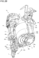
- FIGS. 4A and 4B are side sectional views illustrating the example of the nail gun according to the present embodiment, and FIG. 4A illustrates a state in which the cap portion can be opened. FIG. 4B illustrates a state in which the cap portion is held in the closed state.
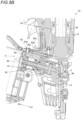
- FIGS. 5A and 5B are side sectional views of a main part illustrating the example of the nail gun according to the present embodiment, and FIG. 5A illustrates a state in which the cap portion can be opened. FIG. 5B illustrates a state in which the cap portion is held in the closed state.
- FIGS. 6A and 6B are bottom sectional views of a main part illustrating the example of the nail gun according to the present embodiment, and FIG. 6A illustrates a state in which the cap portion can be opened. FIG. 6B illustrates a state in which the cap portion is held in the closed state.
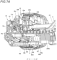
- FIGS. 7A and 7B are sectional perspective views of a main part illustrating an example of the nail gun according to the present embodiment, and FIG. 7A illustrates a state in which the cap portion can be opened. FIG. 7B illustrates a state in which the cap portion is held in the closed state.
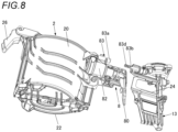
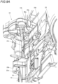
- FIG. 8 is an exploded perspective view of a main part illustrating the example of the nail gun according to the present embodiment.
- a nail gun 1A includes a magazine 2 that accommodates nails 200, and a main body portion 10 having a mechanism for driving out the nails 200, a mechanism for receiving an operation of driving out the nails 200, an injection passage for the nails 200, and the like.
- the main body portion 10 includes a trunk portion 11 provided with a striking portion 3 and the like for driving out the nails 200, and a handle portion 12 extending in a direction intersecting the trunk portion 11.
- the main body portion 10 includes a nose portion 13 having an injection passage 13a through which the nails 200 accommodated in the magazine 2 are supplied.
- the nail gun 1A includes a feeding portion 8 that feeds the nails 200 to the injection passage 13a of the nose portion 13. In the nail gun 1A, the nails 200 supplied to the injection passage 13a from the feeding portion 8 are driven out from an injection port 13d of the injection passage 13a by the striking portion 3. The nails 200 driven out by the striking portion 3 passes through the injection passage 13a.
- the nail gun 1A is provided with the magazine 2 on a lower side of the handle portion 12.
- connection band (not shown), and for example, connected nails 200a wound in a spiral shape are accommodated in the magazine 2.
- the magazine 2 includes an accommodation portion 20 in which a spirally wound portion of the connected nails 200a is accommodated, and a first passage portion 21 through which a portion pulled out from the spirally wound portion passes as examples of a supply portion for supplying the nails 200 to the injection passage 13a and a retraction portion for retracting the nails 200 supplied to the injection passage 13a from a portion other than the injection port 13d to the outside of the injection passage 13a.
- the accommodation portion 20 is implemented by a space having a shape capable of accommodating the spirally wound portion of the connected nails 200a.
- the first passage portion 21 extends along a feeding direction of the nails 200 from the accommodation portion 20 toward the nose portion 13.
- the accommodation portion 20 and the first passage portion 21 of the magazine 2 are integrally formed.
- the nose portion 13 includes a second passage portion 13b connected to the injection passage 13a.
- the second passage portion 13b is an example of a passage portion, and extends along the feeding direction of the nails 200 from the accommodation portion 20 toward the nose portion 13.
- the second passage portion 13b is connected to the injection passage 13a on a downstream side of the nails 200 in the above feeding direction, and is connected to the first passage portion 21 on an upstream side of the nails 200 in the above feeding direction.
- the nose portion 13 may not include the second passage portion 13b, and the first passage portion 21 of the magazine 2 may be connected to the injection passage 13a.
- the first passage portion 21 is an example of the passage portion.
- the magazine 2 includes a fastener support portion 20a that rotatably supports the spirally wound portion of the connected nails 200a.
- the fastener support portion 20a includes a support shaft 20b inserted into the center of the spirally wound portion of the connected nails 200a.
- the magazine 2 includes the accommodation portion 20 and a cap portion 22 that opens and closes the first passage portion 21 and a part of the second passage portion 13b on a side close to the first passage portion 21.
- the cap portion 22 includes a first portion 22a with which the accommodation portion 20 is covered, and a second portion 22b with which the first passage portion 21 and a part of the second passage portion 13b on the side close to the first passage portion 21 are covered, which are integrally formed.
- the cap portion 22 opens and closes the accommodation portion 20, the first passage portion 21, and a part of the second passage portion 13b on the side close to the first passage portion 21 in a rotation operation with a shaft 22c as a fulcrum.
- the shaft 22c is supported by a shaft support portion 20c provided in the accommodation portion 20 in the magazine 2.
- the magazine 2 includes a wall portion 20d that constitutes a part of a lower surface of the accommodation portion 20.
- the shaft support portion 20c is provided on the wall portion 20d.
- the cap portion 22 includes a wall portion 22d that constitutes a part of a lower surface of the first portion 22a.
- the wall portion 22d of the cap portion 22 is supported by the shaft 22c.
- One end of the support shaft 20b of the fastener support portion 20a is supported by the shaft 22c.
- the fastener support portion 20a rotates from an accommodation position to a loading position with the shaft 22c as a fulcrum.
- the fastener support portion 20a is biased by a biasing member 20e in an opening direction of the cap portion 22.
- the fastener support portion 20a rotates to the loading position with the shaft 22c as a fulcrum such that the support shaft 20b protrudes in an oblique direction from the accommodation portion 20 by the biasing of the biasing member 20e in conjunction with an operation of opening the cap portion 22.
- the cap portion 22 is biased in the opening direction by a force for the biasing member 20e biasing the fastener support portion 20a, and is held in an open state.
- the nail gun 1A includes a door portion 23 that opens and closes the injection passage 13a and a remaining portion of the second passage portion 13b of the nose portion 13 on a side close to the injection passage 13a.
- the door portion 23 is formed to cover a part or the whole of a side portion of the injection passage 13a intersecting a direction in which the nails 200 is driven out and the remaining portion of the first passage portion 21 other than a portion covered with the second portion 22b of the cap portion 22, and the door portion 23 opens and closes the injection passage 13a and the remaining portion of the second passage portion 13b in a rotation operation with a shaft 23a as a fulcrum.
- the door portion 23 may be formed integrally with the cap portion 22, and the injection passage 13a and the remaining portion of the second passage portion 13b may be opened and closed in an operation of opening and closing the accommodation portion 20 by the cap portion 22.
- the door portion 23 may be fixed to the nose portion 13 and may not be opened or closed.
- the shaft 23a is supported by a shaft support portion 23b provided on the nose portion 13.
- the shaft support portion 23b is provided in the nose portion 13 on an opposite side to the second passage portion 13b connected to the injection passage 13a.
- the door portion 23 includes a door operation unit 23d that receives an operation of releasing the holding of a closed state. When the door operation unit 23d is operated, the door portion 23 is released from being held in the closed state, and the injection passage 13a and the remaining portion of the second passage portion 13b can be opened and closed in the rotation operation with the shaft 23a as a fulcrum.
- the nail gun 1A includes a magazine support portion 24 that movably supports the magazine 2.
- the magazine support portion 24 is an example of the supply portion and the retraction portion, and is provided on the nose portion 13 in this example.
- the magazine support portion 24 constitutes a part of the second passage portion 13b.
- the magazine 2 can slide in the first direction indicated by an arrow A1 and the second direction indicated by an arrow A2 opposite to the first direction along the feeding direction of the nails 200 in the first passage portion 21 and the second passage portion 13b by the guide of the magazine support portion 24.
- a feeding member 80 which will be described later, of the feeding portion 8, which is an example of the supply portion and a retraction portion, is attached to the magazine 2.
- a feed piston 81 and a feed cylinder 82 to be described later are attached to the magazine 2.
- a switching cylinder 83a of a switching unit 83 to be described later is attached to the magazine 2.
- the feeding member 80, the feed piston 81, and the feed cylinder 82 of the feeding portion 8, and the switching cylinder 83a move together with the magazine 2 in the same direction as a movement direction of the magazine 2.
- the cap portion 22 is connected to the magazine 2 via the shaft 22c and moves together with the magazine 2.
- the magazine 2 is moved between a closed position P1 at which the cap portion 22 is held in the closed state and an openable and closable position P2 at which the cap portion 22 is released from the closed state and can be opened and closed.
- the closed position P1 is a first position
- the openable and closable position P2 is a second position.
- the magazine 2 is moved in the first direction indicated by the arrow A1 from the openable and closable position P2 to the closed position P1.
- the first direction is a direction in which the magazine 2 approaches the main body portion 10, in this example, the nose portion 13.
- the magazine 2 is moved in the second direction indicated by the arrow A2 from the closed position P1 to the openable and closable position P2.
- the second direction is a direction in which the magazine 2 is separated from the main body portion 10, in this example, the nose portion 13.
- the door portion 23 includes an engaging portion 23c that is engaged with the cap portion 22 in a state in which the magazine 2 is moved to the closed position P1.
- the cap portion 22 includes an engaged portion 22e that is engaged with the engaging portion 23c in a state in which the magazine 2 is moved to the closed position P1.
- the second portion 22b of the cap portion 22 faces the door portion 23 along the movement direction of the magazine 2.
- the engaged portion 22e is provided in the second portion 22b facing the door portion 23 in the cap portion 22 in which the magazine 2 is closed.
- the engaged portion 22e protrudes from the second portion 22b toward the door portion 23 in an arrow A1 direction along the movement direction of the magazine 2.
- the engaging portion 23c is provided at a portion of the door portion 23 in which the injection passage 13a and the remaining portion of the second passage portion 13b are closed, the portion facing the engaged portion 22e of the cap portion 22 in which the magazine 2 is closed.
- the engaging portion 23c extends along the movement direction of the magazine 2, and is provided with a recessed portion into which the engaged portion 22e can be inserted and removed.
- the magazine 2 is moved in the first direction from the openable and closable position P2 to the closed position P 1 by the guide of the magazine support portion 24, whereby the engaged portion 22e of the cap portion 22 is engaged with the engaging portion 23c of the door portion 23.
- the magazine 2 is moved in the second direction from the closed position P1 to the openable and closable position P2, whereby the engagement between the engaged portion 22e and the engaging portion 23c is released.
- the door portion 23 includes a pressing portion 25 that presses the cap portion 22 in which the magazine 2 is closed.
- the pressing portion 25 has a shape so as to cover a part of the cap portion 22, and moves between a pressing position for pressing the cap portion 22 and a release position for releasing the pressing of the cap portion 22 in a rotation operation with a shaft 25a as a fulcrum.
- the pressing portion 25 is biased by a biasing member 25b such as a torsion coil spring in a rotation direction from the pressing position to the release position.
- a biasing member 25b such as a torsion coil spring
- the pressing portion 25 includes an acting portion 25c that is pressed against the engaged portion 22e.
- the acting portion 25c is provided on a movement path of the engaged portion 22e as the magazine 2 moves.
- the acting portion 25c is pressed against the engaged portion 22e as the magazine 2 moves, and the pressing portion 25 rotates from the release position to the pressing position in the rotation operation with the shaft 25a as a fulcrum.
- the pressing portion 25 is held at the pressing position when the acting portion 25c is pressed against the engaged portion 22e. Further, when the engaged portion 22e is separated from the acting portion 25c as the magazine 2 moves, the pressing portion 25 rotates from the pressing position to the release position by the biasing of the biasing member 25b.
- the nail gun 1A includes an operation unit 26 that receives an operation of moving the magazine 2.
- the operation unit 26 is attached to the accommodation portion 20 of the magazine 2 via a shaft 26a.
- the operation unit 26 includes a holding unit 27 that holds the magazine 2 at the closed position P1 and the openable and closable position P2.
- the holding unit 27 is formed in an elongated hole shape extending along the movement direction of the magazine 2, and is provided with a first engaging recessed portion 27a extending in a direction intersecting with an extending direction of the holding unit 27 at one end in the extending direction.
- the holding unit 27 is provided with a second engaging recessed portion 27b extending in a direction intersecting the extending direction of the holding unit 27 at the other end in the extending direction.
- a shaft 27c provided on a handle portion 12 side is inserted into the holding unit 27.
- the shaft 27c does not move with respect to the movement of the magazine 2.
- the holding unit 27 is displaced with respect to the shaft 27c by the movement of the magazine 2 and the rotation of the operation unit 26 with the shaft 26a as a fulcrum.
- the first engaging recessed portion 27a of the holding unit 27 faces the shaft 27c.
- the operation unit 26 rotates in a first rotation direction indicated by an arrow B 1, which is one direction with the shaft 26a as a fulcrum, the first engaging recessed portion 27a of the holding unit 27 is engaged with the shaft 27c. Accordingly, the magazine 2 is held at the closed position P1.
- the magazine 2 When the magazine 2 is moving to the openable and closable position P2, the second engaging recessed portion 27b of the holding unit 27 faces the shaft 27c.
- the operation unit 26 rotates in the first rotation direction with the shaft 26a as a fulcrum, the second engaging recessed portion 27b of the holding unit 27 is engaged with the shaft 27c. Accordingly, the magazine 2 is held at the openable and closable position P2.
- the magazine 2 and the cap portion 22 integrally move in the first direction by applying a force for rotating the operation unit 26 in the second rotation direction and then moving the operation unit 26 in the first direction indicated by the arrow A1 in a state in which the magazine 2 is moving to the openable and closable position P2.
- the nail gun 1A includes a sub-operation unit 28 that restricts the opening of the cap portion 22 in a state in which the magazine 2 is moved to the openable and closable position P2.
- the sub-operation unit 28 can press the cap portion 22 in which the accommodation portion 20 is closed in the state in which the magazine 2 is moved to the openable and closable position P2.
- the sub-operation unit 28 may press the cap portion 22 in which the accommodation portion 20 is closed in the state in which the magazine 2 is moved to the closed position P1, and may move integrally with the magazine 2 while maintaining the state in which the sub-operation unit 28 presses the cap portion 22 in an operation of moving the magazine 2 from the closed position P1 to the openable and closable position P2.
- the nail gun 1A includes a main valve 4 that switches whether to supply compressed air to the striking portion 3, a starting valve 5 that causes the main valve 4 to operate, and a trigger 6 that switches between a sign-in state in which the starting valve 5 is operable and a sign-off state in which the starting valve 5 is not operable.
- the nail gun 1A includes a contact portion 7 that comes into contact with a material to be driven (not shown) and switches between the sign-in state in which the starting valve 5 is operable and the sign-off state in which the starting valve 5 is not operable.
- the nail gun 1A includes the feeding portion 8 that feeds the nails 200 to the injection passage 13a of the nose portion 13.
- the nail gun 1A is brought into the sign-in state in which the starting valve 5 is operable by an operation of pulling the trigger 6. From the sign-in state, the starting valve 5 is operated by an operation of pressing the contact portion 7 against the material to be driven (not shown). In addition, the nail gun 1A is brought into the sign-in state in which the starting valve 5 is operable by the operation of pressing the contact portion 7 against the material to be driven (not shown). From the sign-in state, the starting valve 5 is operated by the operation of pulling the trigger 6.
- the striking portion 3 is an example of a driving portion, and includes a striking cylinder 30 to which compressed air is supplied.
- the striking cylinder 30 is provided inside the trunk portion 11 so as to extend vertically.
- the striking cylinder 30 is slidably provided with a striking piston 31 in a cylindrical internal space.
- the striking portion 3 protrudes below the striking piston 31, and a driver 32 is attached to the striking piston 31.
- the nail gun 1A includes a blowback chamber 33 connected to the striking cylinder 30.
- the nail gun 1A supplies the compressed air from the striking cylinder 30 to the blowback chamber 33 in an operation of moving the striking piston 31 from a top dead center position to a bottom dead center position.
- the compressed air in the blowback chamber 33 is discharged via the striking cylinder 30, whereby the striking piston 31 returns to the top dead center position by an air pressure of the compressed air supplied from the blowback chamber 33 to below the striking piston 31 of the striking cylinder 30.
- the nail gun 1A causes the feeding portion 8 to operate by an air pressure of the compressed air supplied from the blowback chamber 33 to the feeding portion 8.
- the main valve 4 opens and closes an air flow path connecting the striking cylinder 30 and a main chamber 34 to which compressed air is supplied from an external air compressor (not shown).
- a pilot valve 51 is operated when a valve stem 50 is pressed in a combination of the operation of the trigger 6 and the operation of pressing the contact portion 7 against the material to be driven.
- the starting valve 5 changes an air pressure applied to the main valve 4 by operating the pilot valve 51.
- the main valve 4 is operated by the balance between a biasing force of a main valve spring 40 and the air pressure applied to the main valve 4.
- the feeding portion 8 includes the feeding member 80 that feeds the connected nails 200a, the feed piston 81 connected to the feeding member 80, and the feed cylinder 82 that causes the feed piston 81 to operate as examples of the supply portion and the retraction portion.
- the feeding portion 8 includes the switching unit 83 that switches whether to supply the compressed air from the blowback chamber 33 to the feed cylinder 82.
- the feeding member 80 includes a claw portion 80a protruding to the second passage portion 13b.
- the claw portion 80a of the feeding member 80 is engaged with the nail 200.
- the feeding member 80 is supported movably with respect to the second passage portion 13b.
- the feeding member 80 can move in a direction in which the claw portion 80a approaches the injection passage 13a of the nose portion 13 and a direction in which the claw portion 80a is separated from the injection passage 13a of the nose portion 13.
- the feeding member 80 can move in a direction in which the claw portion 80a protrudes from the second passage portion 13b and a direction in which the claw portion 80a retreats from the second passage portion 13b in a rotation operation with a shaft 80b as a fulcrum.
- the claw portion 80a of the feeding member 80 is located in the second direction from the door portion 23 in a state in which the magazine 2 is moved to the openable and closable position P2 at which the cap portion 22 can be opened and closed. Accordingly, when the cap portion 22 is opened, the claw portion 80a is exposed to the second passage portion 13b even in a state in which the door portion 23 is closed, and the connected nails 200a can be loaded. In a state in which the leading nail 200 of the connected nails 200a is located in the injection passage 13a, the claw portion 80a of the feeding member 80 is engaged with the second nail 200 of the connected nails 200a.
- the feed piston 81 is slidably supported in the feed cylinder 82.
- the feed cylinder 82 is connected to the blowback chamber 33 via a feed flow path 84 and the switching unit 83, and is supplied with the compressed air from the blowback chamber 33.
- the feed piston 81 is operated by the air pressure of the compressed air supplied from the blowback chamber 33 to cause the feeding member 80 to move in the direction separated from the injection passage 13a.
- the feed piston 81 is biased by a biasing member 85 such as a coil spring in a direction in which the feeding member 80 approaches the injection passage 13a.
- a biasing member 85 such as a coil spring
- the switching unit 83 includes the switching cylinder 83a connected to the feed flow path 84 and a switching valve 83b that opens and closes the feed flow path 84.
- the switching valve 83b of the switching unit 83 is slidably supported in the switching cylinder 83a.
- the switching unit 83 switches whether an outflow port 83c formed in the switching valve 83b is connected to the feed flow path 84 or a sealing member 83d provided in the switching valve 83b seals a space between the outflow port 83c and the feed flow path 84 by a relative movement of the switching cylinder 83a and the switching valve 83b.
- the feeding member 80 is attached to the magazine 2.
- the feed piston 81 and the feed cylinder 82 are attached to the magazine 2.
- the switching cylinder 83a of the switching unit 83 is attached to the magazine 2. Accordingly, when the magazine 2 is moved in the first direction by the guide of the magazine support portion 24, the feeding member 80, the feed piston 81, and the feed cylinder 82 of the feeding portion 8, and the switching cylinder 83a move in the first direction together with the magazine 2.
- the feeding member 80, the feed piston 81, the feed cylinder 82, and the switching cylinder 83a move in the second direction together with the magazine 2.
- the switching valve 83b of the switching unit 83 is attached to the nose portion 13. Accordingly, in an operation of moving the magazine 2, a relative position of the switching valve 83b with respect to the switching cylinder 83a changes, whereby the presence or absence of the communication between the outflow port 83c and the feed flow path 84 is switched, and the presence or absence of supply of the compressed air from the blowback chamber 33 to the feed cylinder 82 is switched.
- the feeding member 80 moves from a feeding operation position P5 to a retracted position P6 by moving together with the magazine 2 in an operation of moving the magazine 2 from the closed position P1 to the openable and closable position P2.
- the feeding member 80 moves the connected nails 200a to an injection enable position P3.
- the feeding member 80 moves to the retracted position P6 with the connected nails 200a engaged therewith, the feeding member 80 moves the connected nails 200a to a removable position P4.
- the connected nails 200a are moved from the injection enable position P3 to the removable position P4 in the operation of moving the magazine 2 from the closed position P 1 to the openable and closable position P2.
- the leading nail 200 is located in the injection passage 13a.
- the leading nail 200 retracts from the portion other than the injection port 13d to the outside of the injection passage 13a.
- the cap portion 22 is opened in a state in which the magazine 2 is moved to the openable and closable position P2, whereby the connected nails 200a are exposed to the first passage portion 21 and the second passage portion 13b.
- the feed piston 81 When the magazine 2 is moving to the closed position P1, the feed piston 81 is biased by the biasing member 85, whereby the feeding member 80 is moved to the feeding operation position P5. When the feeding member 80 is moved to the feeding operation position P5, the leading nail 200 of the connected nails 200a engaged with the feeding member 80 is moved to the injection enable position P3.
- the feeding member 80 when the magazine 2 is moving to the closed position P1, after the feeding member 80 is moved from the feeding operation position P5 in the second direction by a predetermined amount by the compressed air being supplied to the feed cylinder 82 in conjunction with an operation of driving the nails 200 by the striking portion 3, the feeding member 80 is moved in the first direction by the decrease in the air pressure in the feed cylinder 82 and the biasing of the biasing member 85 and returns to the feeding operation position P5.
- the feeding operation position P5 is a position at which normal nail feeding for moving the nails 200 to the injection enable position P3 is enabled by a reciprocating movement of the feeding member 80 by supplying the compressed air in conjunction with the operation of driving the nails 200 by the striking portion 3.
- the feeding member 80 When the magazine 2 is moved from the closed position P1 to the openable and closable position P2, the feeding member 80 is moved from the feeding operation position P5 to the retracted position P6. When the feeding member 80 is moved to the retracted position P6, the leading nail 200 of the connected nails 200a engaged with the feeding member 80 is moved from the injection enable position P3 to the removable position P4.
- the removable position P4 is a position at which the nails 200 are separated by a predetermined amount in the second direction from a movement path of the driver 32 passing through the injection passage 13a.
- the retracted position P6 is a position at which the connected nails 200a can be removed from the first passage portion 21 and the second passage portion 13b.
- the retracted position P6 is a position at which the leading nail 200 of the connected nails 200a is not driven even when the driver 32 moves. Therefore, the removable position P4 is also referred to as an injection avoidance position at which the nails 200 are prevented from being driven out.
- the outflow port 83c and the feed flow path 84 are connected to each other by a change in the relative position of the switching valve 83b with respect to the switching cylinder 83a, and the compressed air can be supplied from the blowback chamber 33 to the feed cylinder 82.
- the magazine 2 is moved from the closed position P1 to the openable and closable position P2
- the space between the outflow port 83c and the feed flow path 84 is sealed, and the supply of the compressed air from the blowback chamber 33 to the feed cylinder 82 is blocked.
- the feeding member 80 does not reciprocate in a state of being moved to the retracted position P6.
- the feeding member 80 moved to the retracted position P6 may reciprocate as long as the leading nail 200 of the connected nails 200a engaged with the feeding member 80 does not move to the injection enable position P3.
- the compressed air may be supplied from the blowback chamber 33 to the feed cylinder 82.
- the feeding member 80 is moved between the feeding operation position P5 and the retracted position P6 by moving in the first direction and the second direction similarly to the magazine 2, and may move in a direction different from that of the magazine 2.
- the magazine 2 and the feed cylinder 82 may be moved in an oblique direction gradually separated from the second direction, and the feeding member 80 may be moved in the second direction.
- the feeding member 80 when the feeding member 80 is moved from the feeding operation position P5 in the second direction by the predetermined amount in the state in which the magazine 2 is moving to the closed position P1, the connected nails 200a are restricted from moving in a direction separated from the injection passage 13a.
- the feeding portion 8 includes a restriction portion 86 that switches whether the connected nails 200a are restricted from moving from the injection enable position P3 illustrated in FIG. 7B to the removable position P4 illustrated in FIG. 7A .
- the restriction portion 86 includes a claw portion 86a that is engaged with the nail 200.
- the restriction portion 86 is biased by a biasing member (not shown) in a direction in which the claw portion 86a protrudes from a hole portion 13c of the second passage portion 13b in a rotation operation with a shaft 86b as a fulcrum.
- the restriction portion 86 has a restriction surface 86c implemented by a surface substantially perpendicular to the feeding direction of the connected nails 200a on a side facing the injection passage 13a on the claw portion 86a.
- the restriction portion 86 has an inclined surface 86d implemented by a surface inclined in a direction in which an amount of protrusion from the hole portion 13c decreases toward the accommodation portion 20 with respect to the feeding direction of the connected nails 200a on a side facing the accommodation portion 20 on the claw portion 86a.
- the claw portion 86a of the restriction portion 86 faces the hole portion 13c of the second passage portion 13b as illustrated in FIG. 7B . Accordingly, the restriction portion 86 is biased by a biasing member 86e, so that the restriction portion 86 moves to a movement restriction position P7 at which the claw portion 86a protrudes from the hole portion 13c to a surface side of the second passage portion 13b in the rotation operation with the shaft 86b as a fulcrum.
- the restriction portion 86 is attached to the magazine 2.
- the restriction portion 86 can move integrally with the magazine 2 by the shaft 86b being supported by the feed cylinder 82.
- the restriction portion 86 when the magazine 2 is moved from the closed position P1 to the openable and closable position P2, the inclined surface 86d of the claw portion 86a is pressed against an opening edge of the hole portion 13c. Accordingly, as illustrated in FIG. 7A , the restriction portion 86 moves to a restriction release position P8 at which the restriction portion 86 retracts to a back side of the second passage portion 13b in the rotation operation with the shaft 86b as a fulcrum.
- the cap portion 22 closes the accommodation portion 20, and the cap portion 22 is held in a state in which the accommodation portion 20 is closed. That is, in the magazine 2, the engaged portion 22e of the cap portion 22 is engaged with the engaging portion 23c of the door portion 23.
- the first engaging recessed portion 27a of the holding unit 27 of the operation unit 26 faces the shaft 27c.
- the operation unit 26 rotates in the first rotation direction with the shaft 26a as a fulcrum, the first engaging recessed portion 27a of the holding unit 27 is engaged with the shaft 27c.
- the acting portion 25c When the magazine 2 is moving to the closed position P1, the acting portion 25c is pressed against the engaged portion 22e, and the pressing portion 25 rotates from the release position to the pressing position in the rotation operation with the shaft 25a as a fulcrum and is held at the pressing position. Accordingly, the magazine 2 is held at the closed position P1.
- the outflow port 83c is connected to the feed flow path 84 by the relative movement of the switching cylinder 83a and the switching valve 83b of the switching unit 83 of the feeding portion 8.
- the magazine 2 In order to open the cap portion 22, the magazine 2 is moved in the second direction. Therefore, first, the operation unit 26 is moved in a direction in which the magazine 2 is moved in the second direction. When the operation unit 26 receives a force for moving the magazine 2 in the second direction, the operation unit 26 rotates in the second rotation direction with the shaft 26a as a fulcrum. When the operation unit 26 rotates in the second rotation direction, the engagement between the first engaging recessed portion 27a and the shaft 27c is released. Accordingly, the magazine 2 can move from the closed position P1 to the openable and closable position P2.
- the accommodation portion 20 and the cap portion 22 integrally move in the second direction by an operation of further moving the operation unit 26 in the second direction.
- the engaged portion 22e is disengaged from the engaging portion 23c, and the engagement between the engaged portion 22e and the engaging portion 23c is released.
- the operation of releasing the engagement between the first engaging recessed portion 27a and the shaft 27c and the operation of moving the magazine 2 from the closed position P1 to the openable and closable position P2 can be performed simultaneously.
- the cap portion 22 can be opened toward the accommodation portion 20.
- the fastener support portion 20a is biased by the biasing member 20e in the opening direction of the cap portion 22, whereby the cap portion 22 is opened in conjunction with the fastener support portion 20a.
- the first passage portion 21 is separated from the second passage portion 13b.
- the feeding member 80 of the feeding portion 8 moves in the second direction in conjunction with the magazine 2.
- the restriction portion 86 moves to the restriction release position P8 at which the claw portion 86a retracts to the back side of the second passage portion 13b.
- the nail 200 is engaged with the claw portion 80a, whereby the connected nails 200a are moved in the second direction, and the leading nail 200 is moved from the injection passage 13a to a first passage portion 21 side and retreats from the injection passage 13a.
- the feeding portion 8 seals the space between the outflow port 83c and the feed flow path 84 with the sealing member 83d by the relative movement of the switching cylinder 83a and the switching valve 83b of the switching unit 83. Accordingly, in the state in which the magazine 2 is moving to the openable and closable position P2, even when the nail gun 1A is operated, the compressed air is not supplied to the feeding portion 8, and the feeding portion 8 does not operate.
- the spirally wound portion of the connected nails 200a is inserted into the support shaft 20b of the fastener support portion 20a.
- the fastener support portion 20a rotates to the accommodation position due to a weight of the connected nails 200a as the connected nails 200a are loaded.
- the cap portion 22 is closed. In the state in which the magazine 2 is moving to the openable and closable position P2, the cap portion 22 is not held in a closed state even when the cap portion 22 is closed.
- the magazine 2 After the cap portion 22 is closed, the magazine 2 is moved in the first direction. Therefore, first, the operation unit 26 rotates in the second rotation direction with the shaft 26a as a fulcrum. When the operation unit 26 rotates in the second rotation direction, the engagement between the second engaging recessed portion 27b and the shaft 27c is released. Accordingly, the magazine 2 can move from the openable and closable position P2 to the closed position P1 by moving the operation unit 26 in a direction of moving in the first direction. When a force for directly pressing the magazine 2 to cause the magazine 2 to move in the first direction is applied after the cap portion 22 is closed, the engagement between the second engaging recessed portion 27b and the shaft 27c is held until a predetermined load is applied.
- the operation unit 26 rotates in the second rotation direction with the shaft 26a as a fulcrum, and the engagement between the second engaging recessed portion 27b and the shaft 27c is released. Accordingly, the magazine 2 can also be moved from the openable and closable position P2 to the closed position P1 by directly pressing the magazine 2 in the direction of moving in the first direction.
- the accommodation portion 20 and the cap portion 22 of the magazine 2 integrally move in the first direction in an operation of further moving the operation unit 26 in the first direction.
- the magazine 2 is moved from the openable and closable position P2 to the closed position P1 in the state in which the cap portion 22 is closed, the engaged portion 22e presses the acting portion 25c of the pressing portion 25.
- the pressing portion 25 rotates from the release position to the pressing position in the rotation operation with the shaft 25a as a fulcrum.
- the pressing portion 25 is held at the pressing position when the acting portion 25c is pressed against the engaged portion 22e.
- the engaged portion 22e is engaged with the engaging portion 23c. Accordingly, the magazine 2 is moved to the closed position P1, whereby the cap portion 22 is held in the state in which the accommodation portion 20 is closed. In addition, the cap portion 22 in the closed state is pressed by the pressing portion 25.
- the magazine 2 When the magazine 2 is moved from the openable and closable position P2 to the closed position P1, the first passage portion 21 and the second passage portion 13b are connected to each other.
- the feeding member 80 of the feeding portion 8 is moved in the first direction in conjunction with the magazine 2. Accordingly, when the magazine 2 is moved to the closed position P1 in the state in which the nails 200 are accommodated in the magazine 2, the nail 200 is engaged with the claw portion 80a, whereby the nails 200 are moved in the first direction, and the leading nail 200 is moved to the injection passage 13a.
- the restriction portion 86 moves to the movement restriction position P7 at which the claw portion 86a protrudes from the hole portion 13c to the surface side of the second passage portion 13b. Accordingly, the restriction portion 86 restricts the connected nails 200a moving in the direction separated from the injection passage 13a.
- the outflow port 83c is connected to the feed flow path 84 by the relative movement of the switching cylinder 83a and the switching valve 83b of the switching unit 83 of the feeding portion 8. Accordingly, in the state in which the magazine 2 is moving to the closed position P1, when the nail gun 1A is operated, the compressed air is supplied to the feeding portion 8 at a predetermined timing, and the feeding portion 8 is operated.
- the nail gun 1A can also be operated to open the cap portion 22 by releasing the holding of the door portion 23 in the closed state and opening the door portion 23 in the operation of the door operation unit 23d, similarly to the configuration in the related art. That is, when the door portion 23 is opened, the engaging portion 23c is disengaged from a position at which the engaging portion 23c is engaged with the engaged portion 22e, and the pressing portion 25 is disengaged from a position at which the cap portion 22 is pressed. Accordingly, when the door portion 23 is opened, the cap portion 22 is opened, and the claw portion 80a of the feeding member 80 is exposed.
- the magazine 2 is moved from the closed position P1 to the openable and closable position P2, and the cap portion 22 is opened.
- the connected nails 200a are moved to the removable position P4.
- the leading nail 200 of the connected nails 200a is moved from the injection passage 13a to the first passage portion 21 side and retreats from the injection passage 13a.
- the connected nails 200a are exposed to the first passage portion 21 and the second passage portion 13b.
- the portion pulled out from the spirally wound portion of the connected nails 200a is taken out from the first passage portion 21 and the second passage portion 13b, and the spirally wound portion of the connected nails 200a can be removed from the fastener support portion 20a and taken out from the accommodation portion 20.
- the valve stem 50 of the starting valve 5 is pressed in the combination of the operation of the trigger 6 and the operation of pressing the contact portion 7 against the material to be driven.
- the valve stem 50 when the valve stem 50 is moved from a standby position, the balance of an air pressure of compressed air applied to the pilot valve 51 changes, whereby the pilot valve 51 is operated and is moved from the standby position.
- the striking portion 3 supplies the compressed air to the striking cylinder 30.
- the striking piston 31 to which the driver 32 is attached is pressed by the air pressure, and moves downward from the top dead center position to the bottom dead center position.
- the striking portion 3 drives the nails 200 positioned in the injection passage 13a into the material to be driven by the driver 32.
- the blowback chamber 33 is supplied with the air on an upper side of the striking piston 31, and a pressure in the blowback chamber 33 increases.
- the restriction portion 86 When the magazine 2 is moving to the closed position P1, the restriction portion 86 is moved to the movement restriction position P7 at which the claw portion 86a protrudes from the hole portion 13c to the surface side of the second passage portion 13b as illustrated in FIG. 7B .
- the feeding member 80 When the feeding member 80 is moved in the direction separated from the injection passage 13a, the nail 200 comes into contact with the restriction surface 86c of the claw portion 86a of the restriction portion 86. Accordingly, the restriction portion 86 restricts the connected nails 200a moving in the direction separated from the injection passage 13a.
- the claw portion 80a is pressed against the nail 200 and retracts from the second passage portion 13b in the rotation operation with a shaft 80b as a fulcrum.
- the claw portion 80a protrudes to the second passage portion 13b and is engaged with the next nail 200.
- the operator moves the nail gun 1A in a direction separated from the material to be driven. Further, the operation of the trigger 6 ends.
- the valve stem 50 of the starting valve 5 returns to the standby position.
- the balance of the air pressure of the compressed air applied to the pilot valve 51 changes, whereby the pilot valve 51 returns to the standby position.
- the striking portion 3 when the main valve 4 is closed, the supply of the compressed air to the striking cylinder 30 is stopped, and the air in the striking cylinder 30 is discharged, whereby a pressure in the striking cylinder 30 decreases.
- the pressure in the striking cylinder 30 decreases, the compressed air in the blowback chamber 33 is supplied to a space below the striking piston 31, and the striking piston 31 moves to the top dead center position.
- blowback chamber 33 when the compressed air is supplied from the blowback chamber 33 to the striking cylinder 30, the pressure in the blowback chamber 33 decreases.
- the air in the feed cylinder 82 flows into the blowback chamber 33 and is discharged via the striking cylinder 30, whereby the air pressure in the feed cylinder 82 decreases.
- the feeding portion 8 when the air pressure in the feed cylinder 82 decreases, an air pressure applied to the feed piston 81 decreases, and the feeding member 80 connected to the feed piston 81 moves in the direction approaching the injection passage 13a by the biasing of the biasing member 85.
- the feeding member 80 moves in the direction approaching the injection passage 13a, the feeding portion 8 feeds the next nail 200 engaged with the claw portion 80a to the injection passage 13a.
- the further next nail 200 of the connected nails 200a comes into contact with the inclined surface 86d of the claw portion 86a of the restriction portion 86. Accordingly, the inclined surface 86d of the claw portion 86a is pressed against the nail 200, and the restriction portion 86 retracts from the second passage portion 13b.
- the restriction portion 86 restricts that when the leading nail 200 of the connected nails 200a is fed to the injection passage 13a and the nail 200 passes through the claw portion 86a, the claw portion 86a protrudes to the second passage portion 13b, and the connected nails 200a move in the direction separated from the injection passage 13a. Accordingly, the next nail 200 can be driven.
- FIGS. 9A and 9B are perspective views of a main part illustrating an example of a nail gun according to a modification of the present embodiment, and FIG. 9A illustrates a state in which the cap portion can be opened. FIG. 9B illustrates a state in which the cap portion is held in the closed state.
- the pressing portion 25 moves to the release position at which the pressing of the cap portion 22 is released, whereby the pressing portion 25 retreats from the movement path of the engaged portion 22e in the operation of opening the cap portion 22. Accordingly, an amount of movement of the magazine 2 until the engagement between the engaged portion 22e and the engaging portion 23c is released is reduced. In addition, a force for holding the cap portion 22 in the closed state is dispersed by the engagement between the engaged portion 22e and the engaging portion 23c and a force by which the pressing portion 25 presses the cap portion 22.
- a nail gun 1B according to the modification does not include the pressing portion 25, and thus the length of the portion at which the engaged portion 22e and the engaging portion 23c are engaged with each other is increased by increasing the length of the engaged portion 22e, and the force for holding the cap portion 22 in the closed state is secured by the engagement between the engaged portion 22e and the engaging portion 23c.
- the nail gun 1B does not include the pressing portion 25, and thus the number of components to be moved can be reduced.
- FIG. 10 is a perspective view of a main part illustrating an example of a nail gun according to a second embodiment
- FIGS. 11A , 11B , 12A , and 12B are side views of a main part illustrating the example of the nail gun according to the second embodiment.
- FIGS. 11A and 11B illustrate a state in which the restriction of the movement of the contact portion 7 is released according to the position of the magazine 2
- FIGS. 12A and 12B illustrate a state in which the movement of the contact portion 7 is restricted according to the position of the magazine 2.
- the nail gun 1C includes a contact restriction portion 70 that restricts the movement of the contact portion 7 according to the position of the magazine 2.
- the contact portion 7 is provided so as to be movable in a third direction along an extending direction of the injection passage 13a from a third position at which the starting valve 5 is not operable to a fourth position at which the starting valve 5 is operable as illustrated in FIG. 4A and the like, and is provided so as to be movable in a fourth direction opposite to the third direction from the fourth position to the third position.
- the third position is, for example, the standby position.
- the third position may be a position at which the contact portion 7 is moved in the third direction from the standby position as long as the starting valve 5 is in a non-operation range even when the trigger 6 is operated.
- the fourth position is, for example, the top dead center position as long as the contact portion 7 is brought into the sign-in state in which the starting valve 5 is operable.
- a configuration is also conceivable in which the contact portion 7 is moved in the third direction from the third position and is brought into the sign-in state at a position before reaching the top dead center position.
- the fourth position may be a position at which the contact portion 7 is moved in the fourth direction from the top dead center position as long as the contact portion 7 is brought into the sign-in state.
- the contact portion 7 switches between the sign-off state in which the starting valve 5 is not operable at the third position and the sign-in state in which the starting valve 5 is operable by moving in the third direction from the third position to the fourth position.
- the contact restriction portion 70 restricts the movement of the contact portion 7 to the fourth position.
- the contact restriction portion 70 includes a contact restriction lever 71 and a biasing member 72 that biases the contact restriction lever 71.
- the contact restriction lever 71 is supported by the nose portion 13 via a shaft 73 and rotates with the shaft 73 as a fulcrum.
- An axial direction in which the shaft 73 extends is a direction intersecting a direction in which the magazine 2 moves.
- the contact portion 7 includes an engaged portion 7b that is engaged with the contact restriction lever 71.
- the engaged portion 7b is implemented by a portion located on the outer periphery of the nose portion 13 with which the injection passage 13a is covered in the contact portion 7.
- the magazine 2 includes an engaging portion 2a that causes the contact restriction lever 71 to operate.
- the engaging portion 2a is implemented by a portion supported by the magazine support portion 24 in the magazine 2.
- the engaging portion 2a moves integrally with the magazine 2 along the magazine support portion 24 in a direction separated from and in a direction approaching the nose portion 13.
- the nail gun 1C includes a movement path 7a through which the engaged portion 7b passes.
- the movement path 7a is formed on the outer periphery of the nose portion 13 with which the injection passage 13a is covered at a portion along the extending direction of the injection passage 13a.
- the engaged portion 7b passes through the movement path 7a in the operation of moving the contact portion 7 in the third direction from the third position to the fourth position and an operation of moving the contact portion 7 in the fourth direction from the fourth position to the third position.
- the nail gun 1C includes a movement path 24a through which the engaging portion 2a passes.
- the movement path 24a is formed at a portion along the movement direction of the magazine 2 that moves by the guide of the magazine support portion 24.
- the engaging portion 2a passes through the movement path 24a in an operation of moving the magazine 2 in the first direction from the closed position P1 to the openable and closable position P2 and an operation of moving the magazine 2 in the second direction from the openable and closable position P2 to the closed position P1.
- the contact restriction lever 71 includes a protruding portion 71a that protrudes and retreats from the movement path 7a of the contact portion 7 and can be engaged with the engaged portion 7b of the contact portion 7, and an engaged portion 71b that protrudes and retreats from the movement path 24a of the magazine 2 and can be engaged with and disengaged from the engaging portion 2a of the magazine 2.
- the protruding portion 71a has a shape extending from a portion supported by the shaft 73 in one direction intersecting the shaft 73.
- the engaged portion 71b has a shape extending from the portion supported by the shaft 73 in another direction that intersects the shaft 73 and is different from the one direction.
- the contact restriction lever 71 is configured such that the protruding portion 71a and the engaged portion 71b move in the same direction along the movement direction of the magazine 2. Therefore, in the contact restriction lever 71, for example, an angle formed by a direction in which the protruding portion 71a extends and a direction in which the engaged portion 71b extends is an acute angle. Accordingly, when the protruding portion 71a of the contact restriction lever 71 rotates with the shaft 73 as a fulcrum in an arrow C1 direction from the outside of the movement path 7a toward the movement path 7a, the protruding portion 71a and the engaged portion 71b move in the same arrow C1 direction.
- the contact restriction lever 71 moves between a restriction position at which the movement of the contact portion 7 is restricted and a restriction release position at which the restriction of the movement of the contact portion 7 is released in a rotation operation with the shaft 73 as a fulcrum. That is, the contact restriction lever 71 moves to the restriction position by rotating in the arrow C1 direction from the restriction release position.
- the contact restriction lever 71 moves to the restriction position, the direction in which the protruding portion 71a extends becomes a direction along a direction in which the contact portion 7 moves, and the contact restriction lever 71 moves to a position at which the protruding portion 71a protrudes to the movement path 7a.
- the protruding portion 71a protrudes to the movement path 7a, for example, even when the contact portion 7 attempts to move in the third direction from the third position in an operation of pressing the contact portion 7 against the material to be driven (not shown), the engaged portion 7b of the contact portion 7 comes into contact with the protruding portion 71a, and the movement of the contact portion 7 to the fourth position is restricted.
- the contact restriction lever 71 rotates in the same direction, the contact restriction lever 71 moves to a position at which the engaged portion 71b protrudes to the movement path 24a.
- the contact restriction lever 71 moves to the restriction release position by rotating in the arrow C2 direction from the restriction position.
- the direction in which the protruding portion 71a extends becomes a direction inclined with respect to the direction in which the contact portion 7 moves, and the contact restriction lever 71 moves to a position at which the protruding portion 71a retreats outward from the movement path 7a.
- the protruding portion 71a retreats outward from the movement path 7a, for example, when the contact portion 7 is moved in the third direction from the third position in the operation of pressing the contact portion 7 against the material to be driven (not shown), the engaged portion 7b of the contact portion 7 does not come into contact with the protruding portion 71a, and the restriction of the movement of the contact portion 7 to the fourth position is released.
- the contact restriction lever 71 rotates in the same direction, the contact restriction lever 71 moves to a position at which the engaged portion 71b retreats outward from the movement path 24a.
- the biasing member 72 is implemented by a torsion coil spring and the like, and biases the contact restriction lever 71 in the arrow C1 direction.
- the engaging portion 2a moves along the movement path 24a in the operation of moving the magazine 2 from the closed position P1 to the openable and closable position P2 and the operation of moving the magazine 2 from the openable and closable position P2 to the closed position P1.
- the engaging portion 2a moves in a direction approaching the engaged portion 71b of the contact restriction lever 71 in the operation of moving the magazine 2 in the second direction from the openable and closable position P2 to the closed position P1. Accordingly, when the magazine 2 is moved to the closed position P1, the engaging portion 2a is engaged with the engaged portion 71b of the contact restriction lever 71.
- the engaging portion 2a moves in a direction separated from the engaged portion 71b of the contact restriction lever 71 in the operation of moving the magazine 2 in the first direction from the closed position P1 to the openable and closable position P2. Accordingly, when the magazine 2 is moved to the openable and closable position P2, the engagement between the engaging portion 2a and the engaged portion 71b of the contact restriction lever 71 is released.
- the engaging portion 2a of the magazine 2 is engaged with the engaged portion 71b of the contact restriction lever 71 in the operation of moving the magazine 2 from the openable and closable position P2 to the closed position P1.
- the contact restriction lever 71 When the engaging portion 2a of the magazine 2 is engaged with the engaged portion 71b, the contact restriction lever 71 is pressed in a direction in which the engaged portion 71b retreats outward from the movement path 24a in the operation of moving the magazine 2 from the openable and closable position P2 to the closed position P1.
- the contact portion 7 when the contact portion 7 is moved in the third direction from the third position in the operation of pressing the contact portion 7 against the material to be driven (not shown), the engaged portion 7b of the contact portion 7 does not come into contact with the protruding portion 71a, and the contact portion 7 can move to the fourth position at which it is possible to perform the sign-in by which the starting valve 5 is operable.
- the contact portion 7 is pressed against the material to be driven (not shown), whereby the contact portion 7 moves upward to be brought into the sign-in state as illustrated in FIG. 11B .
- the nails can be driven by operating the starting valve 5 in cooperation with the operation of the contact portion 7 and the operation of the trigger 6.
- the engaging portion 2a of the magazine 2 is separated from the engaged portion 71b of the contact restriction lever 71, and the engagement between the engaged portion 71b and the engaging portion 2a is released.
- the contact restriction lever 71 can rotate in a direction in which the engaged portion 71b protrudes to the movement path 24a.
- the contact restriction lever 71 rotates in the arrow C1 direction with the shaft 73 as a fulcrum by the biasing of the biasing member 72. Therefore, when the magazine 2 is moved to the openable and closable position P2, the contact restriction lever 71 moves to the restriction position at which the protruding portion 71a protrudes to the movement path 7a as illustrated in FIG. 12A .
- the feeding member 80 moves from the feeding operation position P5 to the retracted position P6.
- the leading nail 200 of the connected nails 200a engaged with the feeding member 80 is moved from the injection enable position P3 to the removable position P4. Accordingly, when the magazine 2 is moved to the openable and closable position P2, the leading nail 200 of the connected nails 200a is moved to a position at which the leading nail 200 is not driven even when the driver 32 is moved.
- the contact portion 7 is brought into the sign-in state in the operation of attempting to move the contact portion 7 in the state in which the magazine 2 is moved to the openable and closable position P2, and the leading nail 200 of the connected nails 200a moves to the position at which the leading nail 200 is not driven even when the driver 32 is moved.
- the starting valve 5 is operated to perform the operation of driving the nails 200 by the striking portion 3.
- the driving operation is referred to as so-called "idle driving".
- an overload may be applied to the striking portion 3, the nose portion 13, and the like.
- the movement of the contact portion 7 can be restricted by moving the contact restriction lever 71 to the restriction position. Accordingly, in the state in which the magazine 2 is moved to the openable and closable position P2, even when the contact portion 7 is pressed against the material to be driven (not shown), the movement of the contact portion 7 is restricted as illustrated in FIG. 12B . Therefore, the contact portion 7 is not brought into the sign-in state in the operation of attempting to move the contact portion 7, and the starting valve 5 does not operate even when the trigger 6 is operated. Therefore, it is possible to prevent an erroneous operation of the nail gun 1C such as idle driving.
- the contact portion 7 may move as long as the contact portion 7 is not in the sign-in state.
- the contact restriction lever 71 rotates with the shaft 73 as a fulcrum, and the contact restriction lever 71 may move between the restriction position and the restriction release position in a linear movement along the movement direction of the magazine 2.
Landscapes
- Engineering & Computer Science (AREA)
- Mechanical Engineering (AREA)
- Physics & Mathematics (AREA)
- Fluid Mechanics (AREA)
- Portable Nailing Machines And Staplers (AREA)
Abstract
Description
- The present disclosure relates to a driving tool that includes a magazine capable of accommodating fasteners and that injects the fasteners accommodated in the magazine.
- A driving tool that injects fasteners such as screws and nails includes a magazine that accommodates the fasteners. The magazine accommodates a fastener connection body in which a plurality of fasteners are connected by a connection band.
- In such a tool, a nose portion from which the fastener is injected, a magazine cap portion provided in the magazine in order to allow the fastener connection body to be loaded into the magazine, and a door portion provided in the nose portion can be opened and closed, respectively (for example, see
JP5482825B - In the related art, in order to open and close a magazine cap portion provided in a magazine, it is necessary to open and close a door portion provided in a nose portion, and it is necessary to operate another member that holds the magazine cap portion in a closed state. Therefore, it takes time to open and close the magazine cap portion.
- The present disclosure provides a driving tool that facilitates an operation of opening and closing a magazine cap portion.
- According to an illustrative aspect of the present disclosure, a driving tool includes: a main body portion; and a magazine that includes an accommodation portion configured to accommodate a fastener, and a cap portion that opens and closes the accommodation portion, and the magazine being movable in a first direction approaching the main body portion and a second direction separated from the main body portion. The main body portion includes an engaging portion engageable with the cap portion in a state where the cap portion is closed. The cap portion is engaged with the engaging portion by the magazine moving in the first direction, and is disengaged from the engaging portion by the magazine moving in the second direction from a state of being engaged with the engaging portion.
- In the present disclosure, when a magazine is moved in a first direction, a cap portion is engaged with an engaging portion, whereby the cap portion holds an accommodation portion in a closed state. When the magazine is moved in a second direction, the engagement between the cap portion and the engaging portion is released, and the cap portion can be opened and closed.
- In the present disclosure, the cap portion and the engaging portion can be engaged and disengaged in an operation of moving the magazine. Accordingly, the cap portion can release the accommodation portion from being held in the closed state in the operation of moving the magazine, and it is not necessary to operate another member that holds the cap portion in the closed state. Therefore, an operation of opening and closing the cap portion of the magazine becomes easy.
-
-
FIG. 1A is a side view illustrating an example of a nail gun according to the present embodiment; -
FIG. 1B is a side view illustrating the example of the nail gun according to the present embodiment; -
FIG. 2A is a perspective view illustrating the example of the nail gun according to the present embodiment; -
FIG. 2B is a perspective view illustrating the example of the nail gun according to the present embodiment; -
FIG. 3A is a perspective view of a main part illustrating the example of the nail gun according to the present embodiment; -
FIG. 3B is a perspective view of a main part illustrating the example of the nail gun according to the present embodiment; -
FIG. 4A is a side sectional view illustrating the example of the nail gun according to the present embodiment; -
FIG. 4B is a side sectional view illustrating the example of the nail gun according to the present embodiment; -
FIG. 5A is a side sectional view of a main part illustrating the example of the nail gun according to the present embodiment; -
FIG. 5B is a side sectional view of a main part illustrating the example of the nail gun according to the present embodiment; -
FIG. 6A is a bottom sectional view of a main part illustrating the example of the nail gun according to the present embodiment; -
FIG. 6B is a bottom sectional view of a main part illustrating the example of the nail gun according to the present embodiment; -
FIG. 7A is a sectional perspective view of a main part illustrating the example of the nail gun according to the present embodiment; -
FIG. 7B is a sectional perspective view of a main part illustrating the example of the nail gun according to the present embodiment; -
FIG. 8 is an exploded perspective view of a main part illustrating the example of the nail gun according to the present embodiment; -
FIG. 9A is a perspective view of a main part illustrating an example of a nail gun according to a modification of the present embodiment; -
FIG. 9B is a perspective view of a main part illustrating the example of the nail gun according to the modification of the present embodiment; -
FIG. 10 is a perspective view of a main part illustrating an example of a nail gun according to a second embodiment; -
FIG. 11A is a side view of a main part illustrating the example of the nail gun according to the second embodiment; -
FIG. 11B is a side view of a main part illustrating the example of the nail gun according to the second embodiment; -
FIG. 12A is a side view of a main part illustrating the example of the nail gun according to the second embodiment; and -
FIG. 12B is a side view of a main part illustrating the example of the nail gun according to the second embodiment. - Hereinafter, embodiments of a nail gun as an example of a driving tool of the present disclosure will be described with reference to the drawings.
-
FIGS. 1A and1B are side views illustrating an example of a nail gun according to the present embodiment, andFIG. 1A illustrates a state in which a cap portion for opening and closing a magazine is opened.FIG. 1B illustrates a state in which the cap portion is held in a closed state. - Further,
FIGS. 2A and2B are perspective views illustrating the example of the nail gun according to the present embodiment, andFIG. 2A illustrates a state in which the cap portion can be opened.FIG. 2B illustrates a state in which the cap portion is held in the closed state. - Further,
FIGS. 3A and3B are perspective views of a main part illustrating the example of the nail gun according to the present embodiment, andFIG. 3A illustrates a state in which the cap portion can be opened.FIG. 3B illustrates a state in which the cap portion is held in the closed state. - Further,
FIGS. 4A and4B are side sectional views illustrating the example of the nail gun according to the present embodiment, andFIG. 4A illustrates a state in which the cap portion can be opened.FIG. 4B illustrates a state in which the cap portion is held in the closed state. - Further,
FIGS. 5A and5B are side sectional views of a main part illustrating the example of the nail gun according to the present embodiment, andFIG. 5A illustrates a state in which the cap portion can be opened.FIG. 5B illustrates a state in which the cap portion is held in the closed state. - Further,
FIGS. 6A and6B are bottom sectional views of a main part illustrating the example of the nail gun according to the present embodiment, andFIG. 6A illustrates a state in which the cap portion can be opened.FIG. 6B illustrates a state in which the cap portion is held in the closed state. - Further,
FIGS. 7A and7B are sectional perspective views of a main part illustrating an example of the nail gun according to the present embodiment, andFIG. 7A illustrates a state in which the cap portion can be opened.FIG. 7B illustrates a state in which the cap portion is held in the closed state. -
FIG. 8 is an exploded perspective view of a main part illustrating the example of the nail gun according to the present embodiment. - A
nail gun 1A includes amagazine 2 that accommodatesnails 200, and amain body portion 10 having a mechanism for driving out thenails 200, a mechanism for receiving an operation of driving out thenails 200, an injection passage for thenails 200, and the like. Themain body portion 10 includes atrunk portion 11 provided with astriking portion 3 and the like for driving out thenails 200, and ahandle portion 12 extending in a direction intersecting thetrunk portion 11. Themain body portion 10 includes anose portion 13 having aninjection passage 13a through which thenails 200 accommodated in themagazine 2 are supplied. Thenail gun 1A includes a feedingportion 8 that feeds thenails 200 to theinjection passage 13a of thenose portion 13. In thenail gun 1A, thenails 200 supplied to theinjection passage 13a from the feedingportion 8 are driven out from aninjection port 13d of theinjection passage 13a by thestriking portion 3. Thenails 200 driven out by thestriking portion 3 passes through theinjection passage 13a. - In the
nail gun 1A, one side along an extending direction of thetrunk portion 11, which is a side on which thenose portion 13 is provided, is a lower side, and the other side along the extending direction of thetrunk portion 11, which is a side opposite to the side on which thenose portion 13 is provided, is an upper side. Thenail gun 1A is provided with themagazine 2 on a lower side of thehandle portion 12. - In the
nail gun 1A, a plurality ofnails 200 as fasteners are connected by a connection band (not shown), and for example, connectednails 200a wound in a spiral shape are accommodated in themagazine 2. - Next, the
magazine 2 and a mechanism for opening and closing themagazine 2 will be described. Themagazine 2 includes anaccommodation portion 20 in which a spirally wound portion of the connectednails 200a is accommodated, and afirst passage portion 21 through which a portion pulled out from the spirally wound portion passes as examples of a supply portion for supplying thenails 200 to theinjection passage 13a and a retraction portion for retracting thenails 200 supplied to theinjection passage 13a from a portion other than theinjection port 13d to the outside of theinjection passage 13a. - The
accommodation portion 20 is implemented by a space having a shape capable of accommodating the spirally wound portion of the connectednails 200a. Thefirst passage portion 21 extends along a feeding direction of thenails 200 from theaccommodation portion 20 toward thenose portion 13. Theaccommodation portion 20 and thefirst passage portion 21 of themagazine 2 are integrally formed. - The
nose portion 13 includes asecond passage portion 13b connected to theinjection passage 13a. Thesecond passage portion 13b is an example of a passage portion, and extends along the feeding direction of thenails 200 from theaccommodation portion 20 toward thenose portion 13. Thesecond passage portion 13b is connected to theinjection passage 13a on a downstream side of thenails 200 in the above feeding direction, and is connected to thefirst passage portion 21 on an upstream side of thenails 200 in the above feeding direction. Thenose portion 13 may not include thesecond passage portion 13b, and thefirst passage portion 21 of themagazine 2 may be connected to theinjection passage 13a. In such a configuration, thefirst passage portion 21 is an example of the passage portion. - The
magazine 2 includes afastener support portion 20a that rotatably supports the spirally wound portion of the connectednails 200a. Thefastener support portion 20a includes asupport shaft 20b inserted into the center of the spirally wound portion of the connectednails 200a. - The
magazine 2 includes theaccommodation portion 20 and acap portion 22 that opens and closes thefirst passage portion 21 and a part of thesecond passage portion 13b on a side close to thefirst passage portion 21. Thecap portion 22 includes afirst portion 22a with which theaccommodation portion 20 is covered, and asecond portion 22b with which thefirst passage portion 21 and a part of thesecond passage portion 13b on the side close to thefirst passage portion 21 are covered, which are integrally formed. Thecap portion 22 opens and closes theaccommodation portion 20, thefirst passage portion 21, and a part of thesecond passage portion 13b on the side close to thefirst passage portion 21 in a rotation operation with ashaft 22c as a fulcrum. - The
shaft 22c is supported by ashaft support portion 20c provided in theaccommodation portion 20 in themagazine 2. Themagazine 2 includes awall portion 20d that constitutes a part of a lower surface of theaccommodation portion 20. Theshaft support portion 20c is provided on thewall portion 20d. Thecap portion 22 includes awall portion 22d that constitutes a part of a lower surface of thefirst portion 22a. Thewall portion 22d of thecap portion 22 is supported by theshaft 22c. One end of thesupport shaft 20b of thefastener support portion 20a is supported by theshaft 22c. Thefastener support portion 20a rotates from an accommodation position to a loading position with theshaft 22c as a fulcrum. - The
fastener support portion 20a is biased by a biasingmember 20e in an opening direction of thecap portion 22. Thefastener support portion 20a rotates to the loading position with theshaft 22c as a fulcrum such that thesupport shaft 20b protrudes in an oblique direction from theaccommodation portion 20 by the biasing of the biasingmember 20e in conjunction with an operation of opening thecap portion 22. Thecap portion 22 is biased in the opening direction by a force for the biasingmember 20e biasing thefastener support portion 20a, and is held in an open state. - The
nail gun 1A includes adoor portion 23 that opens and closes theinjection passage 13a and a remaining portion of thesecond passage portion 13b of thenose portion 13 on a side close to theinjection passage 13a. Thedoor portion 23 is formed to cover a part or the whole of a side portion of theinjection passage 13a intersecting a direction in which thenails 200 is driven out and the remaining portion of thefirst passage portion 21 other than a portion covered with thesecond portion 22b of thecap portion 22, and thedoor portion 23 opens and closes theinjection passage 13a and the remaining portion of thesecond passage portion 13b in a rotation operation with ashaft 23a as a fulcrum. Thedoor portion 23 may be formed integrally with thecap portion 22, and theinjection passage 13a and the remaining portion of thesecond passage portion 13b may be opened and closed in an operation of opening and closing theaccommodation portion 20 by thecap portion 22. Thedoor portion 23 may be fixed to thenose portion 13 and may not be opened or closed. - The
shaft 23a is supported by ashaft support portion 23b provided on thenose portion 13. Theshaft support portion 23b is provided in thenose portion 13 on an opposite side to thesecond passage portion 13b connected to theinjection passage 13a. Thedoor portion 23 includes adoor operation unit 23d that receives an operation of releasing the holding of a closed state. When thedoor operation unit 23d is operated, thedoor portion 23 is released from being held in the closed state, and theinjection passage 13a and the remaining portion of thesecond passage portion 13b can be opened and closed in the rotation operation with theshaft 23a as a fulcrum. - The
nail gun 1A includes amagazine support portion 24 that movably supports themagazine 2. Themagazine support portion 24 is an example of the supply portion and the retraction portion, and is provided on thenose portion 13 in this example. Themagazine support portion 24 constitutes a part of thesecond passage portion 13b. - The
magazine 2 can slide in the first direction indicated by an arrow A1 and the second direction indicated by an arrow A2 opposite to the first direction along the feeding direction of thenails 200 in thefirst passage portion 21 and thesecond passage portion 13b by the guide of themagazine support portion 24. A feedingmember 80, which will be described later, of the feedingportion 8, which is an example of the supply portion and a retraction portion, is attached to themagazine 2. Further, afeed piston 81 and afeed cylinder 82 to be described later are attached to themagazine 2. In addition, aswitching cylinder 83a of aswitching unit 83 to be described later is attached to themagazine 2. Accordingly, when themagazine 2 is moved by the guide of themagazine support portion 24, the feedingmember 80, thefeed piston 81, and thefeed cylinder 82 of the feedingportion 8, and theswitching cylinder 83a move together with themagazine 2 in the same direction as a movement direction of themagazine 2. - The
cap portion 22 is connected to themagazine 2 via theshaft 22c and moves together with themagazine 2. - The
magazine 2 is moved between a closed position P1 at which thecap portion 22 is held in the closed state and an openable and closable position P2 at which thecap portion 22 is released from the closed state and can be opened and closed. The closed position P1 is a first position, and the openable and closable position P2 is a second position. - The
magazine 2 is moved in the first direction indicated by the arrow A1 from the openable and closable position P2 to the closed position P1. The first direction is a direction in which themagazine 2 approaches themain body portion 10, in this example, thenose portion 13. In addition, themagazine 2 is moved in the second direction indicated by the arrow A2 from the closed position P1 to the openable and closable position P2. The second direction is a direction in which themagazine 2 is separated from themain body portion 10, in this example, thenose portion 13. - The
door portion 23 includes an engagingportion 23c that is engaged with thecap portion 22 in a state in which themagazine 2 is moved to the closed position P1. Thecap portion 22 includes an engagedportion 22e that is engaged with the engagingportion 23c in a state in which themagazine 2 is moved to the closed position P1. When themagazine 2 is closed in a state in which themagazine 2 is moved to the openable and closable position P2, thesecond portion 22b of thecap portion 22 faces thedoor portion 23 along the movement direction of themagazine 2. The engagedportion 22e is provided in thesecond portion 22b facing thedoor portion 23 in thecap portion 22 in which themagazine 2 is closed. The engagedportion 22e protrudes from thesecond portion 22b toward thedoor portion 23 in an arrow A1 direction along the movement direction of themagazine 2. The engagingportion 23c is provided at a portion of thedoor portion 23 in which theinjection passage 13a and the remaining portion of thesecond passage portion 13b are closed, the portion facing the engagedportion 22e of thecap portion 22 in which themagazine 2 is closed. The engagingportion 23c extends along the movement direction of themagazine 2, and is provided with a recessed portion into which the engagedportion 22e can be inserted and removed. - Accordingly, the
magazine 2 is moved in the first direction from the openable and closable position P2 to theclosed position P 1 by the guide of themagazine support portion 24, whereby the engagedportion 22e of thecap portion 22 is engaged with the engagingportion 23c of thedoor portion 23. In addition, themagazine 2 is moved in the second direction from the closed position P1 to the openable and closable position P2, whereby the engagement between the engagedportion 22e and the engagingportion 23c is released. - The
door portion 23 includes apressing portion 25 that presses thecap portion 22 in which themagazine 2 is closed. Thepressing portion 25 has a shape so as to cover a part of thecap portion 22, and moves between a pressing position for pressing thecap portion 22 and a release position for releasing the pressing of thecap portion 22 in a rotation operation with ashaft 25a as a fulcrum. - The
pressing portion 25 is biased by a biasingmember 25b such as a torsion coil spring in a rotation direction from the pressing position to the release position. - The
pressing portion 25 includes an actingportion 25c that is pressed against the engagedportion 22e. The actingportion 25c is provided on a movement path of the engagedportion 22e as themagazine 2 moves. - The acting
portion 25c is pressed against the engagedportion 22e as themagazine 2 moves, and thepressing portion 25 rotates from the release position to the pressing position in the rotation operation with theshaft 25a as a fulcrum. Thepressing portion 25 is held at the pressing position when the actingportion 25c is pressed against the engagedportion 22e. Further, when the engagedportion 22e is separated from the actingportion 25c as themagazine 2 moves, thepressing portion 25 rotates from the pressing position to the release position by the biasing of the biasingmember 25b. - The
nail gun 1A includes anoperation unit 26 that receives an operation of moving themagazine 2. Theoperation unit 26 is attached to theaccommodation portion 20 of themagazine 2 via ashaft 26a. - The
operation unit 26 includes a holdingunit 27 that holds themagazine 2 at the closed position P1 and the openable and closable position P2. - The holding
unit 27 is formed in an elongated hole shape extending along the movement direction of themagazine 2, and is provided with a first engaging recessedportion 27a extending in a direction intersecting with an extending direction of the holdingunit 27 at one end in the extending direction. In addition, the holdingunit 27 is provided with a second engaging recessedportion 27b extending in a direction intersecting the extending direction of the holdingunit 27 at the other end in the extending direction. - A
shaft 27c provided on ahandle portion 12 side is inserted into the holdingunit 27. Theshaft 27c does not move with respect to the movement of themagazine 2. On the other hand, the holdingunit 27 is displaced with respect to theshaft 27c by the movement of themagazine 2 and the rotation of theoperation unit 26 with theshaft 26a as a fulcrum. - When the
magazine 2 is moving to the closed position P1, the first engaging recessedportion 27a of the holdingunit 27 faces theshaft 27c. When theoperation unit 26 rotates in a first rotation direction indicated by anarrow B 1, which is one direction with theshaft 26a as a fulcrum, the first engaging recessedportion 27a of the holdingunit 27 is engaged with theshaft 27c. Accordingly, themagazine 2 is held at the closed position P1. - In a state in which the holding
unit 27 is moving to the closed position P1 and in a state in which the first engaging recessedportion 27a is engaged with theshaft 27c, when theoperation unit 26 rotates in a second rotation direction indicated by an arrow B2, which is another direction, with theshaft 26a as a fulcrum, the engagement between the first engaging recessedportion 27a and theshaft 27c is released. Accordingly, themagazine 2 can move from the closed position P1 to the openable and closable position P2. Therefore, themagazine 2 and thecap portion 22 integrally move in the second direction by applying a force for rotating theoperation unit 26 in the second rotation direction and then moving theoperation unit 26 in the second direction indicated by the arrow A2 in a state in which themagazine 2 is moving to the closed position P1. - When the
magazine 2 is moving to the openable and closable position P2, the second engaging recessedportion 27b of the holdingunit 27 faces theshaft 27c. When theoperation unit 26 rotates in the first rotation direction with theshaft 26a as a fulcrum, the second engaging recessedportion 27b of the holdingunit 27 is engaged with theshaft 27c. Accordingly, themagazine 2 is held at the openable and closable position P2. - In a state in which the holding
unit 27 is moving to the openable and closable position P2 and in a state in which the second engaging recessedportion 27b is engaged with theshaft 27c, when theoperation unit 26 rotates in the second rotation direction indicated by the arrow B2 with theshaft 26a as a fulcrum, the engagement between the second engaging recessedportion 27b and theshaft 27c is released. Accordingly, themagazine 2 can move from the openable and closable position P2 to the closed position P1. Therefore, themagazine 2 and thecap portion 22 integrally move in the first direction by applying a force for rotating theoperation unit 26 in the second rotation direction and then moving theoperation unit 26 in the first direction indicated by the arrow A1 in a state in which themagazine 2 is moving to the openable and closable position P2. - The
nail gun 1A includes asub-operation unit 28 that restricts the opening of thecap portion 22 in a state in which themagazine 2 is moved to the openable and closable position P2. Thesub-operation unit 28 can press thecap portion 22 in which theaccommodation portion 20 is closed in the state in which themagazine 2 is moved to the openable and closable position P2. Thesub-operation unit 28 may press thecap portion 22 in which theaccommodation portion 20 is closed in the state in which themagazine 2 is moved to the closed position P1, and may move integrally with themagazine 2 while maintaining the state in which thesub-operation unit 28 presses thecap portion 22 in an operation of moving themagazine 2 from the closed position P1 to the openable and closable position P2. - Next, the mechanism for driving out the
nail 200, the mechanism for receiving an operation for driving out thenails 200, a mechanism for feeding thenails 200, and the like will be described. Thenail gun 1A includes amain valve 4 that switches whether to supply compressed air to thestriking portion 3, a startingvalve 5 that causes themain valve 4 to operate, and atrigger 6 that switches between a sign-in state in which the startingvalve 5 is operable and a sign-off state in which the startingvalve 5 is not operable. In addition, thenail gun 1A includes acontact portion 7 that comes into contact with a material to be driven (not shown) and switches between the sign-in state in which the startingvalve 5 is operable and the sign-off state in which the startingvalve 5 is not operable. Further, thenail gun 1A includes the feedingportion 8 that feeds thenails 200 to theinjection passage 13a of thenose portion 13. Thenail gun 1A is brought into the sign-in state in which the startingvalve 5 is operable by an operation of pulling thetrigger 6. From the sign-in state, the startingvalve 5 is operated by an operation of pressing thecontact portion 7 against the material to be driven (not shown). In addition, thenail gun 1A is brought into the sign-in state in which the startingvalve 5 is operable by the operation of pressing thecontact portion 7 against the material to be driven (not shown). From the sign-in state, the startingvalve 5 is operated by the operation of pulling thetrigger 6. - The
striking portion 3 is an example of a driving portion, and includes astriking cylinder 30 to which compressed air is supplied. Thestriking cylinder 30 is provided inside thetrunk portion 11 so as to extend vertically. Thestriking cylinder 30 is slidably provided with astriking piston 31 in a cylindrical internal space. Thestriking portion 3 protrudes below thestriking piston 31, and adriver 32 is attached to thestriking piston 31. - The
nail gun 1A includes ablowback chamber 33 connected to thestriking cylinder 30. Thenail gun 1A supplies the compressed air from thestriking cylinder 30 to theblowback chamber 33 in an operation of moving thestriking piston 31 from a top dead center position to a bottom dead center position. When thenail gun 1A is brought into the sign-off state and the air on thestriking piston 31 of thestriking cylinder 30 is discharged, the compressed air in theblowback chamber 33 is discharged via thestriking cylinder 30, whereby thestriking piston 31 returns to the top dead center position by an air pressure of the compressed air supplied from theblowback chamber 33 to below thestriking piston 31 of thestriking cylinder 30. In addition, thenail gun 1A causes the feedingportion 8 to operate by an air pressure of the compressed air supplied from theblowback chamber 33 to the feedingportion 8. - The
main valve 4 opens and closes an air flow path connecting thestriking cylinder 30 and amain chamber 34 to which compressed air is supplied from an external air compressor (not shown). In the startingvalve 5, apilot valve 51 is operated when avalve stem 50 is pressed in a combination of the operation of thetrigger 6 and the operation of pressing thecontact portion 7 against the material to be driven. The startingvalve 5 changes an air pressure applied to themain valve 4 by operating thepilot valve 51. Themain valve 4 is operated by the balance between a biasing force of amain valve spring 40 and the air pressure applied to themain valve 4. - The feeding
portion 8 includes the feedingmember 80 that feeds the connectednails 200a, thefeed piston 81 connected to the feedingmember 80, and thefeed cylinder 82 that causes thefeed piston 81 to operate as examples of the supply portion and the retraction portion. In addition, the feedingportion 8 includes the switchingunit 83 that switches whether to supply the compressed air from theblowback chamber 33 to thefeed cylinder 82. - The feeding
member 80 includes aclaw portion 80a protruding to thesecond passage portion 13b. Theclaw portion 80a of the feedingmember 80 is engaged with thenail 200. The feedingmember 80 is supported movably with respect to thesecond passage portion 13b. The feedingmember 80 can move in a direction in which theclaw portion 80a approaches theinjection passage 13a of thenose portion 13 and a direction in which theclaw portion 80a is separated from theinjection passage 13a of thenose portion 13. In addition, the feedingmember 80 can move in a direction in which theclaw portion 80a protrudes from thesecond passage portion 13b and a direction in which theclaw portion 80a retreats from thesecond passage portion 13b in a rotation operation with ashaft 80b as a fulcrum. Theclaw portion 80a of the feedingmember 80 is located in the second direction from thedoor portion 23 in a state in which themagazine 2 is moved to the openable and closable position P2 at which thecap portion 22 can be opened and closed. Accordingly, when thecap portion 22 is opened, theclaw portion 80a is exposed to thesecond passage portion 13b even in a state in which thedoor portion 23 is closed, and the connectednails 200a can be loaded. In a state in which theleading nail 200 of the connectednails 200a is located in theinjection passage 13a, theclaw portion 80a of the feedingmember 80 is engaged with thesecond nail 200 of the connectednails 200a. - The
feed piston 81 is slidably supported in thefeed cylinder 82. Thefeed cylinder 82 is connected to theblowback chamber 33 via afeed flow path 84 and the switchingunit 83, and is supplied with the compressed air from theblowback chamber 33. - The
feed piston 81 is operated by the air pressure of the compressed air supplied from theblowback chamber 33 to cause the feedingmember 80 to move in the direction separated from theinjection passage 13a. Thefeed piston 81 is biased by a biasingmember 85 such as a coil spring in a direction in which the feedingmember 80 approaches theinjection passage 13a. When an air pressure in thefeed cylinder 82 decreases as a result of the air in thefeed cylinder 82 flowing into theblowback chamber 33 and being discharged via thestriking cylinder 30, thefeed piston 81 moves the feedingmember 80 in a direction approaching theinjection passage 13a by the biasing force of the biasingmember 85. - The switching
unit 83 includes theswitching cylinder 83a connected to thefeed flow path 84 and a switchingvalve 83b that opens and closes thefeed flow path 84. The switchingvalve 83b of the switchingunit 83 is slidably supported in theswitching cylinder 83a. The switchingunit 83 switches whether anoutflow port 83c formed in the switchingvalve 83b is connected to thefeed flow path 84 or a sealingmember 83d provided in the switchingvalve 83b seals a space between theoutflow port 83c and thefeed flow path 84 by a relative movement of theswitching cylinder 83a and the switchingvalve 83b. - The feeding
member 80 is attached to themagazine 2. In addition, thefeed piston 81 and thefeed cylinder 82 are attached to themagazine 2. Further, theswitching cylinder 83a of the switchingunit 83 is attached to themagazine 2. Accordingly, when themagazine 2 is moved in the first direction by the guide of themagazine support portion 24, the feedingmember 80, thefeed piston 81, and thefeed cylinder 82 of the feedingportion 8, and theswitching cylinder 83a move in the first direction together with themagazine 2. In addition, when themagazine 2 is moved in the second direction by the guide of themagazine support portion 24, the feedingmember 80, thefeed piston 81, thefeed cylinder 82, and theswitching cylinder 83a move in the second direction together with themagazine 2. - The switching
valve 83b of the switchingunit 83 is attached to thenose portion 13. Accordingly, in an operation of moving themagazine 2, a relative position of the switchingvalve 83b with respect to theswitching cylinder 83a changes, whereby the presence or absence of the communication between theoutflow port 83c and thefeed flow path 84 is switched, and the presence or absence of supply of the compressed air from theblowback chamber 33 to thefeed cylinder 82 is switched. - The feeding
member 80 moves from a feeding operation position P5 to a retracted position P6 by moving together with themagazine 2 in an operation of moving themagazine 2 from the closed position P1 to the openable and closable position P2. When the feedingmember 80 moves to the feeding operation position P5 with the connectednails 200a engaged therewith, the feedingmember 80 moves the connectednails 200a to an injection enable position P3. In addition, when the feedingmember 80 moves to the retracted position P6 with the connectednails 200a engaged therewith, the feedingmember 80 moves the connectednails 200a to a removable position P4. - Accordingly, in the
nail gun 1A, the connectednails 200a are moved from the injection enable position P3 to the removable position P4 in the operation of moving themagazine 2 from theclosed position P 1 to the openable and closable position P2. When the connectednails 200a are moving to the injection enable position P3, the leadingnail 200 is located in theinjection passage 13a. In addition, when the connectednails 200a are moved to the removable position P4, the leadingnail 200 retracts from the portion other than theinjection port 13d to the outside of theinjection passage 13a. Further, when the connectednails 200a are moved to the removable position P4, thecap portion 22 is opened in a state in which themagazine 2 is moved to the openable and closable position P2, whereby the connectednails 200a are exposed to thefirst passage portion 21 and thesecond passage portion 13b. - When the
magazine 2 is moving to the closed position P1, thefeed piston 81 is biased by the biasingmember 85, whereby the feedingmember 80 is moved to the feeding operation position P5. When the feedingmember 80 is moved to the feeding operation position P5, the leadingnail 200 of the connectednails 200a engaged with the feedingmember 80 is moved to the injection enable position P3. - In the
nail gun 1A, when themagazine 2 is moving to the closed position P1, after the feedingmember 80 is moved from the feeding operation position P5 in the second direction by a predetermined amount by the compressed air being supplied to thefeed cylinder 82 in conjunction with an operation of driving thenails 200 by thestriking portion 3, the feedingmember 80 is moved in the first direction by the decrease in the air pressure in thefeed cylinder 82 and the biasing of the biasingmember 85 and returns to the feeding operation position P5. - Accordingly, the feeding operation position P5 is a position at which normal nail feeding for moving the
nails 200 to the injection enable position P3 is enabled by a reciprocating movement of the feedingmember 80 by supplying the compressed air in conjunction with the operation of driving thenails 200 by thestriking portion 3. - When the
magazine 2 is moved from the closed position P1 to the openable and closable position P2, the feedingmember 80 is moved from the feeding operation position P5 to the retracted position P6. When the feedingmember 80 is moved to the retracted position P6, the leadingnail 200 of the connectednails 200a engaged with the feedingmember 80 is moved from the injection enable position P3 to the removable position P4. The removable position P4 is a position at which thenails 200 are separated by a predetermined amount in the second direction from a movement path of thedriver 32 passing through theinjection passage 13a. - Accordingly, the retracted position P6 is a position at which the connected
nails 200a can be removed from thefirst passage portion 21 and thesecond passage portion 13b. In addition, the retracted position P6 is a position at which theleading nail 200 of the connectednails 200a is not driven even when thedriver 32 moves. Therefore, the removable position P4 is also referred to as an injection avoidance position at which thenails 200 are prevented from being driven out. - When the
magazine 2 is moving to the closed position P1, theoutflow port 83c and thefeed flow path 84 are connected to each other by a change in the relative position of the switchingvalve 83b with respect to theswitching cylinder 83a, and the compressed air can be supplied from theblowback chamber 33 to thefeed cylinder 82. On the other hand, when themagazine 2 is moved from the closed position P1 to the openable and closable position P2, the space between theoutflow port 83c and thefeed flow path 84 is sealed, and the supply of the compressed air from theblowback chamber 33 to thefeed cylinder 82 is blocked. - Accordingly, in a state in which the
magazine 2 is moved to the openable and closable position P2, even when the operation of driving thenails 200 by thestriking portion 3 is performed, the feedingmember 80 does not reciprocate in a state of being moved to the retracted position P6. On the other hand, the feedingmember 80 moved to the retracted position P6 may reciprocate as long as the leadingnail 200 of the connectednails 200a engaged with the feedingmember 80 does not move to the injection enable position P3. In this case, even when themagazine 2 is moved from the closed position P1 to the openable and closable position P2, the compressed air may be supplied from theblowback chamber 33 to thefeed cylinder 82. - The feeding
member 80 is moved between the feeding operation position P5 and the retracted position P6 by moving in the first direction and the second direction similarly to themagazine 2, and may move in a direction different from that of themagazine 2. For example, in order to move the feedingmember 80 from the feeding operation position P5 to the retracted position P6, themagazine 2 and thefeed cylinder 82 may be moved in an oblique direction gradually separated from the second direction, and the feedingmember 80 may be moved in the second direction. - As described above, in the
nail gun 1A, when the feedingmember 80 is moved from the feeding operation position P5 in the second direction by the predetermined amount in the state in which themagazine 2 is moving to the closed position P1, the connectednails 200a are restricted from moving in a direction separated from theinjection passage 13a. - Therefore, the feeding
portion 8 includes arestriction portion 86 that switches whether the connectednails 200a are restricted from moving from the injection enable position P3 illustrated inFIG. 7B to the removable position P4 illustrated inFIG. 7A . - The
restriction portion 86 includes aclaw portion 86a that is engaged with thenail 200. Therestriction portion 86 is biased by a biasing member (not shown) in a direction in which theclaw portion 86a protrudes from ahole portion 13c of thesecond passage portion 13b in a rotation operation with ashaft 86b as a fulcrum. - The
restriction portion 86 has arestriction surface 86c implemented by a surface substantially perpendicular to the feeding direction of the connectednails 200a on a side facing theinjection passage 13a on theclaw portion 86a. In addition, therestriction portion 86 has aninclined surface 86d implemented by a surface inclined in a direction in which an amount of protrusion from thehole portion 13c decreases toward theaccommodation portion 20 with respect to the feeding direction of the connectednails 200a on a side facing theaccommodation portion 20 on theclaw portion 86a. - When the
magazine 2 is moving to the closed position P1 as illustrated inFIG. 4B , theclaw portion 86a of therestriction portion 86 faces thehole portion 13c of thesecond passage portion 13b as illustrated inFIG. 7B . Accordingly, therestriction portion 86 is biased by a biasingmember 86e, so that therestriction portion 86 moves to a movement restriction position P7 at which theclaw portion 86a protrudes from thehole portion 13c to a surface side of thesecond passage portion 13b in the rotation operation with theshaft 86b as a fulcrum. - The
restriction portion 86 is attached to themagazine 2. In this example, therestriction portion 86 can move integrally with themagazine 2 by theshaft 86b being supported by thefeed cylinder 82. As illustrated inFIG. 4A , in therestriction portion 86, when themagazine 2 is moved from the closed position P1 to the openable and closable position P2, theinclined surface 86d of theclaw portion 86a is pressed against an opening edge of thehole portion 13c. Accordingly, as illustrated inFIG. 7A , therestriction portion 86 moves to a restriction release position P8 at which therestriction portion 86 retracts to a back side of thesecond passage portion 13b in the rotation operation with theshaft 86b as a fulcrum. - Next, an example of the operation of opening and closing the
cap portion 22 will be described. - When the
magazine 2 is moving to the closed position P1, thecap portion 22 closes theaccommodation portion 20, and thecap portion 22 is held in a state in which theaccommodation portion 20 is closed. That is, in themagazine 2, the engagedportion 22e of thecap portion 22 is engaged with the engagingportion 23c of thedoor portion 23. - When the
magazine 2 is moving to the closed position P1, the first engaging recessedportion 27a of the holdingunit 27 of theoperation unit 26 faces theshaft 27c. When theoperation unit 26 rotates in the first rotation direction with theshaft 26a as a fulcrum, the first engaging recessedportion 27a of the holdingunit 27 is engaged with theshaft 27c. - When the
magazine 2 is moving to the closed position P1, the actingportion 25c is pressed against the engagedportion 22e, and thepressing portion 25 rotates from the release position to the pressing position in the rotation operation with theshaft 25a as a fulcrum and is held at the pressing position. Accordingly, themagazine 2 is held at the closed position P1. - When the
magazine 2 is moving to the closed position P1, theoutflow port 83c is connected to thefeed flow path 84 by the relative movement of theswitching cylinder 83a and the switchingvalve 83b of the switchingunit 83 of the feedingportion 8. - In order to open the
cap portion 22, themagazine 2 is moved in the second direction. Therefore, first, theoperation unit 26 is moved in a direction in which themagazine 2 is moved in the second direction. When theoperation unit 26 receives a force for moving themagazine 2 in the second direction, theoperation unit 26 rotates in the second rotation direction with theshaft 26a as a fulcrum. When theoperation unit 26 rotates in the second rotation direction, the engagement between the first engaging recessedportion 27a and theshaft 27c is released. Accordingly, themagazine 2 can move from the closed position P1 to the openable and closable position P2. - In the
magazine 2, theaccommodation portion 20 and thecap portion 22 integrally move in the second direction by an operation of further moving theoperation unit 26 in the second direction. When themagazine 2 is moved from the closed position P1 to the openable and closable position P2, the engagedportion 22e is disengaged from the engagingportion 23c, and the engagement between the engagedportion 22e and the engagingportion 23c is released. In this way, by moving theoperation unit 26 in the direction in which themagazine 2 is moved in the second direction, the operation of releasing the engagement between the first engaging recessedportion 27a and theshaft 27c and the operation of moving themagazine 2 from the closed position P1 to the openable and closable position P2 can be performed simultaneously. - When the
magazine 2 is moved from the closed position P1 to the openable and closable position P2, the engagedportion 22e is separated from the actingportion 25c, and thepressing portion 25 rotates from the pressing position to the release position by the biasing of the biasingmember 25b. - Accordingly, the
cap portion 22 can be opened toward theaccommodation portion 20. In a state in which thenails 200 are not accommodated in themagazine 2, thefastener support portion 20a is biased by the biasingmember 20e in the opening direction of thecap portion 22, whereby thecap portion 22 is opened in conjunction with thefastener support portion 20a. - When the
magazine 2 is moved from the closed position P1 to the openable and closable position P2, thefirst passage portion 21 is separated from thesecond passage portion 13b. Further, when themagazine 2 is moved from the closed position P1 to the openable and closable position P2, the feedingmember 80 of the feedingportion 8 moves in the second direction in conjunction with themagazine 2. When themagazine 2 is moved from the closed position P1 to the openable and closable position P2, therestriction portion 86 moves to the restriction release position P8 at which theclaw portion 86a retracts to the back side of thesecond passage portion 13b. Accordingly, when themagazine 2 is moved to the openable and closable position P2 in a state in which thenails 200 are accommodated in themagazine 2, thenail 200 is engaged with theclaw portion 80a, whereby the connectednails 200a are moved in the second direction, and theleading nail 200 is moved from theinjection passage 13a to afirst passage portion 21 side and retreats from theinjection passage 13a. - When the
magazine 2 is moved to the openable and closable position P2, the feedingportion 8 seals the space between theoutflow port 83c and thefeed flow path 84 with the sealingmember 83d by the relative movement of theswitching cylinder 83a and the switchingvalve 83b of the switchingunit 83. Accordingly, in the state in which themagazine 2 is moving to the openable and closable position P2, even when thenail gun 1A is operated, the compressed air is not supplied to the feedingportion 8, and the feedingportion 8 does not operate. - When the
magazine 2 is moved to the openable and closable position P2 and the force for moving themagazine 2 in the second direction is not applied to theoperation unit 26 in the state in which the second engaging recessedportion 27b faces theshaft 27c, theoperation unit 26 rotates in the first rotation direction with theshaft 26a as a fulcrum. Whenoperation unit 26 rotates in the first rotation direction, the second engaging recessedportion 27b is engaged with theshaft 27c. Accordingly, themagazine 2 is held at the openable and closable position P2. - In order to load the
nails 200 into themagazine 2, the spirally wound portion of the connectednails 200a is inserted into thesupport shaft 20b of thefastener support portion 20a. Thefastener support portion 20a rotates to the accommodation position due to a weight of the connectednails 200a as theconnected nails 200a are loaded. - When the
nails 200 are loaded into themagazine 2, a portion pulled out from the spirally wound portion of the connectednails 200a is loaded into thefirst passage portion 21 and thesecond passage portion 13b. In a state in which thecap portion 22 is opened, theclaw portion 80a of the feedingmember 80 is exposed to thesecond passage portion 13b. Accordingly, thenail 200 is engaged with theclaw portion 80a in the operation of loading the portion pulled out from the spirally wound portion of the connectednails 200a into thefirst passage portion 21 and thesecond passage portion 13b. Theleading nail 200 does not need to be loaded into theinjection passage 13a of thenose portion 13 in an operation of loading the connectednails 200a into thefirst passage portion 21 and thesecond passage portion 13b. - After the
nails 200 are loaded into themagazine 2, thecap portion 22 is closed. In the state in which themagazine 2 is moving to the openable and closable position P2, thecap portion 22 is not held in a closed state even when thecap portion 22 is closed. - After the
cap portion 22 is closed, themagazine 2 is moved in the first direction. Therefore, first, theoperation unit 26 rotates in the second rotation direction with theshaft 26a as a fulcrum. When theoperation unit 26 rotates in the second rotation direction, the engagement between the second engaging recessedportion 27b and theshaft 27c is released. Accordingly, themagazine 2 can move from the openable and closable position P2 to the closed position P1 by moving theoperation unit 26 in a direction of moving in the first direction. When a force for directly pressing themagazine 2 to cause themagazine 2 to move in the first direction is applied after thecap portion 22 is closed, the engagement between the second engaging recessedportion 27b and theshaft 27c is held until a predetermined load is applied. When themagazine 2 is directly pressed and the predetermined load is applied, theoperation unit 26 rotates in the second rotation direction with theshaft 26a as a fulcrum, and the engagement between the second engaging recessedportion 27b and theshaft 27c is released. Accordingly, themagazine 2 can also be moved from the openable and closable position P2 to the closed position P1 by directly pressing themagazine 2 in the direction of moving in the first direction. - The
accommodation portion 20 and thecap portion 22 of themagazine 2 integrally move in the first direction in an operation of further moving theoperation unit 26 in the first direction. When themagazine 2 is moved from the openable and closable position P2 to the closed position P1 in the state in which thecap portion 22 is closed, the engagedportion 22e presses the actingportion 25c of thepressing portion 25. When the actingportion 25c is pressed against the engagedportion 22e, thepressing portion 25 rotates from the release position to the pressing position in the rotation operation with theshaft 25a as a fulcrum. Thepressing portion 25 is held at the pressing position when the actingportion 25c is pressed against the engagedportion 22e. - When the
magazine 2 is moved from the openable and closable position P2 to the closed position P1 in the state in which thecap portion 22 is closed, the engagedportion 22e is engaged with the engagingportion 23c. Accordingly, themagazine 2 is moved to the closed position P1, whereby thecap portion 22 is held in the state in which theaccommodation portion 20 is closed. In addition, thecap portion 22 in the closed state is pressed by thepressing portion 25. - When the
magazine 2 is moved from the openable and closable position P2 to the closed position P1, thefirst passage portion 21 and thesecond passage portion 13b are connected to each other. In addition, when themagazine 2 is moved from the openable and closable position P2 to the closed position P1, the feedingmember 80 of the feedingportion 8 is moved in the first direction in conjunction with themagazine 2. Accordingly, when themagazine 2 is moved to the closed position P1 in the state in which thenails 200 are accommodated in themagazine 2, thenail 200 is engaged with theclaw portion 80a, whereby thenails 200 are moved in the first direction, and theleading nail 200 is moved to theinjection passage 13a. - When the
magazine 2 is moved from the openable and closable position P2 to the closed position P1, therestriction portion 86 moves to the movement restriction position P7 at which theclaw portion 86a protrudes from thehole portion 13c to the surface side of thesecond passage portion 13b. Accordingly, therestriction portion 86 restricts the connectednails 200a moving in the direction separated from theinjection passage 13a. - When the
magazine 2 is moved to the closed position P1, theoutflow port 83c is connected to thefeed flow path 84 by the relative movement of theswitching cylinder 83a and the switchingvalve 83b of the switchingunit 83 of the feedingportion 8. Accordingly, in the state in which themagazine 2 is moving to the closed position P1, when thenail gun 1A is operated, the compressed air is supplied to the feedingportion 8 at a predetermined timing, and the feedingportion 8 is operated. - When the
magazine 2 is moved to the closed position P1 and the force for moving themagazine 2 in the first direction is not applied to theoperation unit 26 in the state in which the first engaging recessedportion 27a faces theshaft 27c, theoperation unit 26 rotates in the first rotation direction with theshaft 26a as a fulcrum. Whenoperation unit 26 rotates in the first rotation direction, the first engaging recessedportion 27a is engaged with theshaft 27c. Accordingly, themagazine 2 is held at the closed position P1. - The
nail gun 1A can also be operated to open thecap portion 22 by releasing the holding of thedoor portion 23 in the closed state and opening thedoor portion 23 in the operation of thedoor operation unit 23d, similarly to the configuration in the related art. That is, when thedoor portion 23 is opened, the engagingportion 23c is disengaged from a position at which the engagingportion 23c is engaged with the engagedportion 22e, and thepressing portion 25 is disengaged from a position at which thecap portion 22 is pressed. Accordingly, when thedoor portion 23 is opened, thecap portion 22 is opened, and theclaw portion 80a of the feedingmember 80 is exposed. - When the connected
nails 200a used halfway are taken out for replacement or the like, as described above, themagazine 2 is moved from the closed position P1 to the openable and closable position P2, and thecap portion 22 is opened. - In the
nail gun 1A, when themagazine 2 is moved to the openable and closable position P2 in a state in which the connectednails 200a are moving to the injection enable position P3, the connectednails 200a are moved to the removable position P4. When the connectednails 200a are moved to the removable position P4, the leadingnail 200 of the connectednails 200a is moved from theinjection passage 13a to thefirst passage portion 21 side and retreats from theinjection passage 13a. In addition, the connectednails 200a are exposed to thefirst passage portion 21 and thesecond passage portion 13b. - Accordingly, the portion pulled out from the spirally wound portion of the connected
nails 200a is taken out from thefirst passage portion 21 and thesecond passage portion 13b, and the spirally wound portion of the connectednails 200a can be removed from thefastener support portion 20a and taken out from theaccommodation portion 20. - Next, the operation of driving the
nails 200 by thenail gun 1A will be described. As described above, when thenails 200 are loaded into themagazine 2 in the operation of moving themagazine 2 from the openable and closable position P2 to the closed position P1, the leadingnail 200 is located in theinjection passage 13a. - When the
nails 200 are to be driven by thenail gun 1A, an operator presses thecontact portion 7 against the material to be driven (not shown) and operates thetrigger 6. - The valve stem 50 of the starting
valve 5 is pressed in the combination of the operation of thetrigger 6 and the operation of pressing thecontact portion 7 against the material to be driven. In the startingvalve 5, when thevalve stem 50 is moved from a standby position, the balance of an air pressure of compressed air applied to thepilot valve 51 changes, whereby thepilot valve 51 is operated and is moved from the standby position. - when the
pilot valve 51 is moved from the standby position, the balance between an air pressure of compressed air applied to themain valve 4 and the biasing force of themain valve spring 40 changes, whereby themain valve 4 is opened. - When the
main valve 4 is opened, thestriking portion 3 supplies the compressed air to thestriking cylinder 30. When thestriking portion 3 supplies the compressed air to thestriking cylinder 30, thestriking piston 31 to which thedriver 32 is attached is pressed by the air pressure, and moves downward from the top dead center position to the bottom dead center position. As thestriking piston 31 moves from the top dead center position to the bottom dead center position, thestriking portion 3 drives thenails 200 positioned in theinjection passage 13a into the material to be driven by thedriver 32. - When the
striking piston 31 moves downward from the top dead center position in the operation of driving thenails 200, theblowback chamber 33 is supplied with the air on an upper side of thestriking piston 31, and a pressure in theblowback chamber 33 increases. - In the
striking portion 3, when the pressure in theblowback chamber 33 increases, the compressed air in theblowback chamber 33 is supplied from thefeed flow path 84 to thefeed cylinder 82. Accordingly, in the feedingportion 8, the feedingmember 80 connected to thefeed piston 81 is moved in the second direction separated from theinjection passage 13a. - When the
magazine 2 is moving to the closed position P1, therestriction portion 86 is moved to the movement restriction position P7 at which theclaw portion 86a protrudes from thehole portion 13c to the surface side of thesecond passage portion 13b as illustrated inFIG. 7B . When the feedingmember 80 is moved in the direction separated from theinjection passage 13a, thenail 200 comes into contact with therestriction surface 86c of theclaw portion 86a of therestriction portion 86. Accordingly, therestriction portion 86 restricts the connectednails 200a moving in the direction separated from theinjection passage 13a. - When the feeding
member 80 of the feedingportion 8 moves in the direction separated from theinjection passage 13a in the state in which therestriction portion 86 restricts the connectednails 200a from moving in the direction separated from theinjection passage 13a, theclaw portion 80a is pressed against thenail 200 and retracts from thesecond passage portion 13b in the rotation operation with ashaft 80b as a fulcrum. When the feedingmember 80 of the feedingportion 8 moves to a position at which theclaw portion 80a passes through theleading nail 200, theclaw portion 80a protrudes to thesecond passage portion 13b and is engaged with thenext nail 200. - When the driving of the
nails 200 ends, the operator moves thenail gun 1A in a direction separated from the material to be driven. Further, the operation of thetrigger 6 ends. - When the
contact portion 7 is separated from the material to be driven and returns to the standby position by moving thenail gun 1A in the direction separated from the material to be driven or when the operation of thetrigger 6 ends, thevalve stem 50 of the startingvalve 5 returns to the standby position. In the startingvalve 5, when thevalve stem 50 returns to the standby position, the balance of the air pressure of the compressed air applied to thepilot valve 51 changes, whereby thepilot valve 51 returns to the standby position. - when the
pilot valve 51 returns to the standby position, the balance between the air pressure of the compressed air applied to themain valve 4 and the biasing force of themain valve spring 40 changes, whereby themain valve 4 is opened. - In the
striking portion 3, when themain valve 4 is closed, the supply of the compressed air to thestriking cylinder 30 is stopped, and the air in thestriking cylinder 30 is discharged, whereby a pressure in thestriking cylinder 30 decreases. In thestriking portion 3, when the pressure in thestriking cylinder 30 decreases, the compressed air in theblowback chamber 33 is supplied to a space below thestriking piston 31, and thestriking piston 31 moves to the top dead center position. - In the
blowback chamber 33, when the compressed air is supplied from theblowback chamber 33 to thestriking cylinder 30, the pressure in theblowback chamber 33 decreases. - When the compressed air in the
blowback chamber 33 is supplied to thestriking cylinder 30 and the pressure in theblowback chamber 33 decreases, in the feedingportion 8, the air in thefeed cylinder 82 flows into theblowback chamber 33 and is discharged via thestriking cylinder 30, whereby the air pressure in thefeed cylinder 82 decreases. In the feedingportion 8, when the air pressure in thefeed cylinder 82 decreases, an air pressure applied to thefeed piston 81 decreases, and the feedingmember 80 connected to thefeed piston 81 moves in the direction approaching theinjection passage 13a by the biasing of the biasingmember 85. When the feedingmember 80 moves in the direction approaching theinjection passage 13a, the feedingportion 8 feeds thenext nail 200 engaged with theclaw portion 80a to theinjection passage 13a. - In an operation of feeding the
next nail 200 to theinjection passage 13 a, the furthernext nail 200 of the connectednails 200a comes into contact with theinclined surface 86d of theclaw portion 86a of therestriction portion 86. Accordingly, theinclined surface 86d of theclaw portion 86a is pressed against thenail 200, and therestriction portion 86 retracts from thesecond passage portion 13b. Therestriction portion 86 restricts that when theleading nail 200 of the connectednails 200a is fed to theinjection passage 13a and thenail 200 passes through theclaw portion 86a, theclaw portion 86a protrudes to thesecond passage portion 13b, and the connectednails 200a move in the direction separated from theinjection passage 13a. Accordingly, thenext nail 200 can be driven. -
FIGS. 9A and9B are perspective views of a main part illustrating an example of a nail gun according to a modification of the present embodiment, andFIG. 9A illustrates a state in which the cap portion can be opened.FIG. 9B illustrates a state in which the cap portion is held in the closed state. - In the
nail gun 1A including thepressing portion 25, thepressing portion 25 moves to the release position at which the pressing of thecap portion 22 is released, whereby thepressing portion 25 retreats from the movement path of the engagedportion 22e in the operation of opening thecap portion 22. Accordingly, an amount of movement of themagazine 2 until the engagement between the engagedportion 22e and the engagingportion 23c is released is reduced. In addition, a force for holding thecap portion 22 in the closed state is dispersed by the engagement between the engagedportion 22e and the engagingportion 23c and a force by which thepressing portion 25 presses thecap portion 22. Therefore, even if a length of a portion at which the engagedportion 22e and the engagingportion 23c are engaged with each other is reduced, the force for holding thecap portion 22 in the closed state can be secured by the engagement between the engagedportion 22e and the engagingportion 23c. Therefore, by reducing a length of the engagedportion 22e, the amount of movement of themagazine 2 until the engagement between the engagedportion 22e and the engagingportion 23c is released is reduced. - On the other hand, a
nail gun 1B according to the modification does not include thepressing portion 25, and thus the length of the portion at which the engagedportion 22e and the engagingportion 23c are engaged with each other is increased by increasing the length of the engagedportion 22e, and the force for holding thecap portion 22 in the closed state is secured by the engagement between the engagedportion 22e and the engagingportion 23c. Thenail gun 1B does not include thepressing portion 25, and thus the number of components to be moved can be reduced. -
FIG. 10 is a perspective view of a main part illustrating an example of a nail gun according to a second embodiment, andFIGS. 11A ,11B ,12A , and12B are side views of a main part illustrating the example of the nail gun according to the second embodiment. In anail gun 1C according to the second embodiment, configurations similar to those of thenail gun 1A according to the first embodiment are denoted by the same reference numerals.FIGS. 11A and11B illustrate a state in which the restriction of the movement of thecontact portion 7 is released according to the position of themagazine 2, andFIGS. 12A and12B illustrate a state in which the movement of thecontact portion 7 is restricted according to the position of themagazine 2. - The
nail gun 1C includes acontact restriction portion 70 that restricts the movement of thecontact portion 7 according to the position of themagazine 2. Thecontact portion 7 is provided so as to be movable in a third direction along an extending direction of theinjection passage 13a from a third position at which the startingvalve 5 is not operable to a fourth position at which the startingvalve 5 is operable as illustrated inFIG. 4A and the like, and is provided so as to be movable in a fourth direction opposite to the third direction from the fourth position to the third position. When thecontact portion 7 is moving to the standby position, the startingvalve 5 does not operate even when thetrigger 6 is operated. Therefore, the third position is, for example, the standby position. However, the third position may be a position at which thecontact portion 7 is moved in the third direction from the standby position as long as the startingvalve 5 is in a non-operation range even when thetrigger 6 is operated. In addition, when thecontact portion 7 is moved to the top dead center position, the fourth position is, for example, the top dead center position as long as thecontact portion 7 is brought into the sign-in state in which the startingvalve 5 is operable. However, a configuration is also conceivable in which thecontact portion 7 is moved in the third direction from the third position and is brought into the sign-in state at a position before reaching the top dead center position. Therefore, the fourth position may be a position at which thecontact portion 7 is moved in the fourth direction from the top dead center position as long as thecontact portion 7 is brought into the sign-in state. Thecontact portion 7 switches between the sign-off state in which the startingvalve 5 is not operable at the third position and the sign-in state in which the startingvalve 5 is operable by moving in the third direction from the third position to the fourth position. Thecontact restriction portion 70 restricts the movement of thecontact portion 7 to the fourth position. - The
contact restriction portion 70 includes acontact restriction lever 71 and a biasingmember 72 that biases thecontact restriction lever 71. Thecontact restriction lever 71 is supported by thenose portion 13 via ashaft 73 and rotates with theshaft 73 as a fulcrum. An axial direction in which theshaft 73 extends is a direction intersecting a direction in which themagazine 2 moves. - The
contact portion 7 includes an engagedportion 7b that is engaged with thecontact restriction lever 71. The engagedportion 7b is implemented by a portion located on the outer periphery of thenose portion 13 with which theinjection passage 13a is covered in thecontact portion 7. Themagazine 2 includes an engagingportion 2a that causes thecontact restriction lever 71 to operate. The engagingportion 2a is implemented by a portion supported by themagazine support portion 24 in themagazine 2. The engagingportion 2a moves integrally with themagazine 2 along themagazine support portion 24 in a direction separated from and in a direction approaching thenose portion 13. - The
nail gun 1C includes amovement path 7a through which the engagedportion 7b passes. Themovement path 7a is formed on the outer periphery of thenose portion 13 with which theinjection passage 13a is covered at a portion along the extending direction of theinjection passage 13a. The engagedportion 7b passes through themovement path 7a in the operation of moving thecontact portion 7 in the third direction from the third position to the fourth position and an operation of moving thecontact portion 7 in the fourth direction from the fourth position to the third position. Thenail gun 1C includes amovement path 24a through which the engagingportion 2a passes. Themovement path 24a is formed at a portion along the movement direction of themagazine 2 that moves by the guide of themagazine support portion 24. The engagingportion 2a passes through themovement path 24a in an operation of moving themagazine 2 in the first direction from the closed position P1 to the openable and closable position P2 and an operation of moving themagazine 2 in the second direction from the openable and closable position P2 to the closed position P1. - The
contact restriction lever 71 includes a protrudingportion 71a that protrudes and retreats from themovement path 7a of thecontact portion 7 and can be engaged with the engagedportion 7b of thecontact portion 7, and an engagedportion 71b that protrudes and retreats from themovement path 24a of themagazine 2 and can be engaged with and disengaged from the engagingportion 2a of themagazine 2. The protrudingportion 71a has a shape extending from a portion supported by theshaft 73 in one direction intersecting theshaft 73. The engagedportion 71b has a shape extending from the portion supported by theshaft 73 in another direction that intersects theshaft 73 and is different from the one direction. - In this example, the
contact restriction lever 71 is configured such that the protrudingportion 71a and the engagedportion 71b move in the same direction along the movement direction of themagazine 2. Therefore, in thecontact restriction lever 71, for example, an angle formed by a direction in which the protrudingportion 71a extends and a direction in which the engagedportion 71b extends is an acute angle. Accordingly, when the protrudingportion 71a of thecontact restriction lever 71 rotates with theshaft 73 as a fulcrum in an arrow C1 direction from the outside of themovement path 7a toward themovement path 7a, the protrudingportion 71a and the engagedportion 71b move in the same arrow C1 direction. In addition, when the protrudingportion 71a of thecontact restriction lever 71 rotates with theshaft 73 as a fulcrum in an arrow C2 direction from themovement path 7a toward the outside of themovement path 7a, the protrudingportion 71a and the engagedportion 71b move in the same arrow C2 direction. - The
contact restriction lever 71 moves between a restriction position at which the movement of thecontact portion 7 is restricted and a restriction release position at which the restriction of the movement of thecontact portion 7 is released in a rotation operation with theshaft 73 as a fulcrum. That is, thecontact restriction lever 71 moves to the restriction position by rotating in the arrow C1 direction from the restriction release position. When thecontact restriction lever 71 moves to the restriction position, the direction in which the protrudingportion 71a extends becomes a direction along a direction in which thecontact portion 7 moves, and thecontact restriction lever 71 moves to a position at which the protrudingportion 71a protrudes to themovement path 7a. When the protrudingportion 71a protrudes to themovement path 7a, for example, even when thecontact portion 7 attempts to move in the third direction from the third position in an operation of pressing thecontact portion 7 against the material to be driven (not shown), the engagedportion 7b of thecontact portion 7 comes into contact with the protrudingportion 71a, and the movement of thecontact portion 7 to the fourth position is restricted. When thecontact restriction lever 71 rotates in the same direction, thecontact restriction lever 71 moves to a position at which the engagedportion 71b protrudes to themovement path 24a. - On the other hand, the
contact restriction lever 71 moves to the restriction release position by rotating in the arrow C2 direction from the restriction position. When thecontact restriction lever 71 moves to the restriction release position, the direction in which the protrudingportion 71a extends becomes a direction inclined with respect to the direction in which thecontact portion 7 moves, and thecontact restriction lever 71 moves to a position at which the protrudingportion 71a retreats outward from themovement path 7a. When the protrudingportion 71a retreats outward from themovement path 7a, for example, when thecontact portion 7 is moved in the third direction from the third position in the operation of pressing thecontact portion 7 against the material to be driven (not shown), the engagedportion 7b of thecontact portion 7 does not come into contact with the protrudingportion 71a, and the restriction of the movement of thecontact portion 7 to the fourth position is released. When thecontact restriction lever 71 rotates in the same direction, thecontact restriction lever 71 moves to a position at which the engagedportion 71b retreats outward from themovement path 24a. - The biasing
member 72 is implemented by a torsion coil spring and the like, and biases thecontact restriction lever 71 in the arrow C1 direction. - The engaging
portion 2a moves along themovement path 24a in the operation of moving themagazine 2 from the closed position P1 to the openable and closable position P2 and the operation of moving themagazine 2 from the openable and closable position P2 to the closed position P1. - The engaging
portion 2a moves in a direction approaching the engagedportion 71b of thecontact restriction lever 71 in the operation of moving themagazine 2 in the second direction from the openable and closable position P2 to the closed position P1. Accordingly, when themagazine 2 is moved to the closed position P1, the engagingportion 2a is engaged with the engagedportion 71b of thecontact restriction lever 71. - The engaging
portion 2a moves in a direction separated from the engagedportion 71b of thecontact restriction lever 71 in the operation of moving themagazine 2 in the first direction from the closed position P1 to the openable and closable position P2. Accordingly, when themagazine 2 is moved to the openable and closable position P2, the engagement between the engagingportion 2a and the engagedportion 71b of thecontact restriction lever 71 is released. - Next, an operation of switching whether the movement of the
contact portion 7 is restricted according to the position of themagazine 2 in thenail gun 1C according to the second embodiment will be described. In thenail gun 1C, the engagingportion 2a of themagazine 2 is engaged with the engagedportion 71b of thecontact restriction lever 71 in the operation of moving themagazine 2 from the openable and closable position P2 to the closed position P1. - When the engaging
portion 2a of themagazine 2 is engaged with the engagedportion 71b, thecontact restriction lever 71 is pressed in a direction in which the engagedportion 71b retreats outward from themovement path 24a in the operation of moving themagazine 2 from the openable and closable position P2 to the closed position P1. - When the
contact restriction lever 71 is pressed in the direction in which the engagedportion 71b retreats outward from themovement path 24a, thecontact restriction lever 71 rotates in the arrow C2 direction with theshaft 73 as a fulcrum. Accordingly, when themagazine 2 is moved to the closed position P1, thecontact restriction lever 71 moves to the restriction release position at which the protrudingportion 71a retracts outward from themovement path 7a as illustrated inFIG. 11A . Therefore, when thecontact portion 7 is moved in the third direction from the third position in the operation of pressing thecontact portion 7 against the material to be driven (not shown), the engagedportion 7b of thecontact portion 7 does not come into contact with the protrudingportion 71a, and thecontact portion 7 can move to the fourth position at which it is possible to perform the sign-in by which the startingvalve 5 is operable. - Therefore, in a state in which the
magazine 2 is moved to the closed position P1, thecontact portion 7 is pressed against the material to be driven (not shown), whereby thecontact portion 7 moves upward to be brought into the sign-in state as illustrated inFIG. 11B . When thetrigger 6 is further operated, the nails can be driven by operating the startingvalve 5 in cooperation with the operation of thecontact portion 7 and the operation of thetrigger 6. - On the other hand, in the
nail gun 1C, in the operation of moving themagazine 2 from the closed position P1 to the openable and closable position P2, the engagingportion 2a of themagazine 2 is separated from the engagedportion 71b of thecontact restriction lever 71, and the engagement between the engagedportion 71b and the engagingportion 2a is released. - When the engaging
portion 2a of themagazine 2 moves in the direction separated from the engagedportion 71b, thecontact restriction lever 71 can rotate in a direction in which the engagedportion 71b protrudes to themovement path 24a. - Accordingly, when the
magazine 2 is moved from the closed position P1 to the openable and closable position P2, thecontact restriction lever 71 rotates in the arrow C1 direction with theshaft 73 as a fulcrum by the biasing of the biasingmember 72. Therefore, when themagazine 2 is moved to the openable and closable position P2, thecontact restriction lever 71 moves to the restriction position at which the protrudingportion 71a protrudes to themovement path 7a as illustrated inFIG. 12A . Therefore, when thecontact portion 7 attempts to move in the third direction from the third position in the operation of pressing thecontact portion 7 against the material to be driven (not shown), the engagedportion 7b of thecontact portion 7 comes into contact with the protrudingportion 71a, and the movement of thecontact portion 7 to the fourth position is restricted. - As described above, when the
magazine 2 is moved from the closed position P1 to the openable and closable position P2, the feedingmember 80 moves from the feeding operation position P5 to the retracted position P6. When the feedingmember 80 is moved to the retracted position P6, the leadingnail 200 of the connectednails 200a engaged with the feedingmember 80 is moved from the injection enable position P3 to the removable position P4. Accordingly, when themagazine 2 is moved to the openable and closable position P2, the leadingnail 200 of the connectednails 200a is moved to a position at which theleading nail 200 is not driven even when thedriver 32 is moved. - As described above, a case will be considered in which the
contact portion 7 is brought into the sign-in state in the operation of attempting to move thecontact portion 7 in the state in which themagazine 2 is moved to the openable and closable position P2, and theleading nail 200 of the connectednails 200a moves to the position at which theleading nail 200 is not driven even when thedriver 32 is moved. In this case, when thetrigger 6 is further operated, the startingvalve 5 is operated to perform the operation of driving thenails 200 by thestriking portion 3. When the driving operation is performed without the presence of thenail 200 in the movement path of thedriver 32, the driving operation is referred to as so-called "idle driving". In the nail gun, when the idle driving is performed, an overload may be applied to thestriking portion 3, thenose portion 13, and the like. - Therefore, when the
magazine 2 is moved to the openable and closable position P2, the movement of thecontact portion 7 can be restricted by moving thecontact restriction lever 71 to the restriction position. Accordingly, in the state in which themagazine 2 is moved to the openable and closable position P2, even when thecontact portion 7 is pressed against the material to be driven (not shown), the movement of thecontact portion 7 is restricted as illustrated inFIG. 12B . Therefore, thecontact portion 7 is not brought into the sign-in state in the operation of attempting to move thecontact portion 7, and the startingvalve 5 does not operate even when thetrigger 6 is operated. Therefore, it is possible to prevent an erroneous operation of thenail gun 1C such as idle driving. In the state in which themagazine 2 is moved to the openable and closable position P2, when thetrigger 6 is operated, thecontact portion 7 is brought into the sign-in state. However, the movement of thecontact portion 7 is restricted, and thus the startingvalve 5 does not operate in the operation of moving thecontact portion 7. Therefore, it is possible to prevent an erroneous operation of thenail gun 1C such as idle driving. - In the state in which the
contact restriction lever 71 moves to the restriction position, even when thecontact portion 7 is pressed against the material to be driven (not shown), thecontact portion 7 may move as long as thecontact portion 7 is not in the sign-in state. - The
contact restriction lever 71 rotates with theshaft 73 as a fulcrum, and thecontact restriction lever 71 may move between the restriction position and the restriction release position in a linear movement along the movement direction of themagazine 2.
Claims (14)
- A driving tool, comprising:a main body portion; anda magazine that includes an accommodation portion configured to accommodate a fastener, and a cap portion that opens and closes the accommodation portion, and the magazine being movable in a first direction approaching the main body portion and a second direction separated from the main body portion, whereinthe main body portion includes an engaging portion engageable with the cap portion in a state where the cap portion is closed, andthe cap portion is engaged with the engaging portion by the magazine moving in the first direction, and is disengaged from the engaging portion by the magazine moving in the second direction from a state of being engaged with the engaging portion.
- The driving tool according to claim 1, whereinthe main body portion includes a nose portion having an injection passage to which the fastener is supplied, andthe magazine is supported on the nose portion to be slidable in the first direction and the second direction.
- The driving tool according to claim 2, wherein
the magazine includes a biasing member that biases the cap portion in an opening direction of the cap portion. - The driving tool according to claim 3, further comprising:a feeding portion configured to feed the fastener to the injection passage, whereinthe feeding portion includes a feeding member that is engaged with the fastener to feed the fastener in the first direction, andthe feeding member is exposed to an outside in a state where the cap portion is opened.
- The driving tool according to claim 4, wherein
the feeding member is interlocked with movement of the magazine. - The driving tool according to claim 5, wherein
the magazine movably supports the feeding portion. - The driving tool according to claim 2, wherein
the magazine includes a passage portion that is connected to the injection passage by moving in the first direction and is separated from the injection passage by moving in the second direction. - The driving tool according to claim 2, whereinthe nose portion includes a second passage portion that is connected to the injection passage such that the fastener passes through the second passage portion, andthe magazine includes a first passage portion through which the fastener passes and that is connected to the second passage portion by moving in the first direction and is separated from the second passage portion by moving in the second direction.
- The driving tool according to claim 2, whereinthe nose portion further includes a pressing portion configured to press the closed cap portion, andthe pressing portion moves between a pressing position for pressing the cap portion and a release position for releasing the pressing of the cap portion in conjunction with movement of the magazine.
- The driving tool according to claim 1, further comprising:an operation unit configured to receive an operation of moving the magazine, whereinthe operation unit includes a holding unit configured to hold a position of the magazine.
- The driving tool according to claim 10, wherein
the operation unit is configured to release a holding state where the holding unit holds the position of the magazine when receiving a force for moving the magazine in the second direction. - The driving tool according to claim 2, further comprising:a striking portion configured to drive out the fastener by supplying compressed air;a main valve configured to switch whether to supply the compressed air to the striking portion;a starting valve configured to operate the main valve;a contact portion that is provided to be movable from a third position at which the starting valve is not operable to a fourth position at which the starting valve is operable, and that is configured to switch between a sign-in state where the starting valve is operable by moving from the third position to the fourth position and a sign-off state where the starting valve is not operable at the third position; anda contact restriction portion configured to restrict the contact portion from moving to the fourth position in accordance with a position of the magazine.
- The driving tool according to claim 12, wherein
the contact restriction portion includes a contact restriction lever that protrudes to a movement path of the contact portion from the third position to the fourth position by the magazine moving in the second direction to restrict the contact portion moving, and that is configured to retreat from the movement path of the contact portion by the magazine moving in the first direction to release a restriction state where the contact restriction lever restricts the contact portion from moving. - The driving tool according to claim 1, whereinthe main body portion includes an openable and closable door portion provided with the engaging portion,the cap portion includes an engaged portion configured to engage with the engaging portion, andthe magazine is configured to move in the second direction in a state where the door portion is closed.
Applications Claiming Priority (2)
| Application Number | Priority Date | Filing Date | Title |
|---|---|---|---|
| JP2022205722 | 2022-12-22 | ||
| JP2023192978A JP2024091453A (en) | 2022-12-22 | 2023-11-13 | Driving tools |
Publications (3)
| Publication Number | Publication Date |
|---|---|
| EP4389352A1 true EP4389352A1 (en) | 2024-06-26 |
| EP4389352C0 EP4389352C0 (en) | 2025-09-10 |
| EP4389352B1 EP4389352B1 (en) | 2025-09-10 |
Family
ID=89308295
Family Applications (1)
| Application Number | Title | Priority Date | Filing Date |
|---|---|---|---|
| EP23219247.6A Active EP4389352B1 (en) | 2022-12-22 | 2023-12-21 | Driving tool |
Country Status (3)
| Country | Link |
|---|---|
| US (1) | US20240208017A1 (en) |
| EP (1) | EP4389352B1 (en) |
| TW (1) | TW202436038A (en) |
Citations (2)
| Publication number | Priority date | Publication date | Assignee | Title |
|---|---|---|---|---|
| WO2005095063A1 (en) * | 2004-03-31 | 2005-10-13 | Jpf Works Co., Ltd. | Portable type fastener driving tool |
| JP5482825B2 (en) | 2012-05-21 | 2014-05-07 | マックス株式会社 | Magazine for connecting fasteners and driving tool equipped with this magazine |
-
2023
- 2023-12-19 TW TW112149445A patent/TW202436038A/en unknown
- 2023-12-21 EP EP23219247.6A patent/EP4389352B1/en active Active
- 2023-12-21 US US18/393,558 patent/US20240208017A1/en active Pending
Patent Citations (2)
| Publication number | Priority date | Publication date | Assignee | Title |
|---|---|---|---|---|
| WO2005095063A1 (en) * | 2004-03-31 | 2005-10-13 | Jpf Works Co., Ltd. | Portable type fastener driving tool |
| JP5482825B2 (en) | 2012-05-21 | 2014-05-07 | マックス株式会社 | Magazine for connecting fasteners and driving tool equipped with this magazine |
Also Published As
| Publication number | Publication date |
|---|---|
| EP4389352C0 (en) | 2025-09-10 |
| EP4389352B1 (en) | 2025-09-10 |
| TW202436038A (en) | 2024-09-16 |
| US20240208017A1 (en) | 2024-06-27 |
Similar Documents
| Publication | Publication Date | Title |
|---|---|---|
| US11331779B2 (en) | Driving machine | |
| US7866521B2 (en) | Magazine for wired-collated fasteners with automatic loading | |
| EP2450153B1 (en) | Driving tool | |
| US7513403B2 (en) | Idle driving operation preventing devices for fastener driving tools, and fastener driving tools having such devices | |
| US6092711A (en) | Magazine for compressed-air nail firing tool | |
| TWI379745B (en) | Fastener driving machine | |
| EP4389352B1 (en) | Driving tool | |
| JP2024091453A (en) | Driving tools | |
| US7104433B2 (en) | Safety apparatus of air impact driver | |
| US7757921B2 (en) | Driving machine | |
| US12539588B2 (en) | Driving tool | |
| JP2024091454A (en) | Driving tools | |
| US20080121676A1 (en) | Driving tool | |
| JP4420163B2 (en) | Connecting nail supply mechanism for nailing machine | |
| JPH0616669Y2 (en) | Safety mechanism in nailer | |
| US12491613B2 (en) | Driving tool | |
| JPH0437735Y2 (en) | ||
| JPH0546853Y2 (en) | ||
| US20250269499A1 (en) | Screw driving machine | |
| JP5287596B2 (en) | Impact tool | |
| US20240131669A1 (en) | Handheld tool | |
| JPH0544060Y2 (en) | ||
| JP2000334680A (en) | Nailing machine nail removal equipment | |
| HK1066188A (en) | Safety device of air impact screwdriver | |
| JPH03178783A (en) | Nose of fixing tool striking machine |
Legal Events
| Date | Code | Title | Description |
|---|---|---|---|
| PUAI | Public reference made under article 153(3) epc to a published international application that has entered the european phase |
Free format text: ORIGINAL CODE: 0009012 |
|
| STAA | Information on the status of an ep patent application or granted ep patent |
Free format text: STATUS: THE APPLICATION HAS BEEN PUBLISHED |
|
| AK | Designated contracting states |
Kind code of ref document: A1 Designated state(s): AL AT BE BG CH CY CZ DE DK EE ES FI FR GB GR HR HU IE IS IT LI LT LU LV MC ME MK MT NL NO PL PT RO RS SE SI SK SM TR |
|
| STAA | Information on the status of an ep patent application or granted ep patent |
Free format text: STATUS: REQUEST FOR EXAMINATION WAS MADE |
|
| 17P | Request for examination filed |
Effective date: 20240627 |
|
| RBV | Designated contracting states (corrected) |
Designated state(s): AL AT BE BG CH CY CZ DE DK EE ES FI FR GB GR HR HU IE IS IT LI LT LU LV MC ME MK MT NL NO PL PT RO RS SE SI SK SM TR |
|
| STAA | Information on the status of an ep patent application or granted ep patent |
Free format text: STATUS: EXAMINATION IS IN PROGRESS |
|
| 17Q | First examination report despatched |
Effective date: 20241210 |
|
| GRAP | Despatch of communication of intention to grant a patent |
Free format text: ORIGINAL CODE: EPIDOSNIGR1 |
|
| STAA | Information on the status of an ep patent application or granted ep patent |
Free format text: STATUS: GRANT OF PATENT IS INTENDED |
|
| INTG | Intention to grant announced |
Effective date: 20250502 |
|
| GRAS | Grant fee paid |
Free format text: ORIGINAL CODE: EPIDOSNIGR3 |
|
| GRAA | (expected) grant |
Free format text: ORIGINAL CODE: 0009210 |
|
| STAA | Information on the status of an ep patent application or granted ep patent |
Free format text: STATUS: THE PATENT HAS BEEN GRANTED |
|
| AK | Designated contracting states |
Kind code of ref document: B1 Designated state(s): AL AT BE BG CH CY CZ DE DK EE ES FI FR GB GR HR HU IE IS IT LI LT LU LV MC ME MK MT NL NO PL PT RO RS SE SI SK SM TR |
|
| REG | Reference to a national code |
Ref country code: GB Ref legal event code: FG4D |
|
| REG | Reference to a national code |
Ref country code: CH Ref legal event code: EP |
|
| REG | Reference to a national code |
Ref country code: DE Ref legal event code: R096 Ref document number: 602023006583 Country of ref document: DE |
|
| REG | Reference to a national code |
Ref country code: IE Ref legal event code: FG4D |
|
| U01 | Request for unitary effect filed |
Effective date: 20250930 |
|
| U07 | Unitary effect registered |
Designated state(s): AT BE BG DE DK EE FI FR IT LT LU LV MT NL PT RO SE SI Effective date: 20251009 |
|
| U20 | Renewal fee for the european patent with unitary effect paid |
Year of fee payment: 3 Effective date: 20251110 |
|
| PG25 | Lapsed in a contracting state [announced via postgrant information from national office to epo] |
Ref country code: NO Free format text: LAPSE BECAUSE OF FAILURE TO SUBMIT A TRANSLATION OF THE DESCRIPTION OR TO PAY THE FEE WITHIN THE PRESCRIBED TIME-LIMIT Effective date: 20251210 |
|
| PG25 | Lapsed in a contracting state [announced via postgrant information from national office to epo] |
Ref country code: HR Free format text: LAPSE BECAUSE OF FAILURE TO SUBMIT A TRANSLATION OF THE DESCRIPTION OR TO PAY THE FEE WITHIN THE PRESCRIBED TIME-LIMIT Effective date: 20250910 |
|
| PG25 | Lapsed in a contracting state [announced via postgrant information from national office to epo] |
Ref country code: GR Free format text: LAPSE BECAUSE OF FAILURE TO SUBMIT A TRANSLATION OF THE DESCRIPTION OR TO PAY THE FEE WITHIN THE PRESCRIBED TIME-LIMIT Effective date: 20251211 |
|
| PG25 | Lapsed in a contracting state [announced via postgrant information from national office to epo] |
Ref country code: PL Free format text: LAPSE BECAUSE OF FAILURE TO SUBMIT A TRANSLATION OF THE DESCRIPTION OR TO PAY THE FEE WITHIN THE PRESCRIBED TIME-LIMIT Effective date: 20250910 |
|
| PG25 | Lapsed in a contracting state [announced via postgrant information from national office to epo] |
Ref country code: RS Free format text: LAPSE BECAUSE OF FAILURE TO SUBMIT A TRANSLATION OF THE DESCRIPTION OR TO PAY THE FEE WITHIN THE PRESCRIBED TIME-LIMIT Effective date: 20251210 |
|
| PG25 | Lapsed in a contracting state [announced via postgrant information from national office to epo] |
Ref country code: ES Free format text: LAPSE BECAUSE OF FAILURE TO SUBMIT A TRANSLATION OF THE DESCRIPTION OR TO PAY THE FEE WITHIN THE PRESCRIBED TIME-LIMIT Effective date: 20250910 |
|
| PG25 | Lapsed in a contracting state [announced via postgrant information from national office to epo] |
Ref country code: SM Free format text: LAPSE BECAUSE OF FAILURE TO SUBMIT A TRANSLATION OF THE DESCRIPTION OR TO PAY THE FEE WITHIN THE PRESCRIBED TIME-LIMIT Effective date: 20250910 |
|
| PG25 | Lapsed in a contracting state [announced via postgrant information from national office to epo] |
Ref country code: IS Free format text: LAPSE BECAUSE OF FAILURE TO SUBMIT A TRANSLATION OF THE DESCRIPTION OR TO PAY THE FEE WITHIN THE PRESCRIBED TIME-LIMIT Effective date: 20260110 |
|
| PG25 | Lapsed in a contracting state [announced via postgrant information from national office to epo] |
Ref country code: CZ Free format text: LAPSE BECAUSE OF FAILURE TO SUBMIT A TRANSLATION OF THE DESCRIPTION OR TO PAY THE FEE WITHIN THE PRESCRIBED TIME-LIMIT Effective date: 20250910 |
|
| PG25 | Lapsed in a contracting state [announced via postgrant information from national office to epo] |
Ref country code: SK Free format text: LAPSE BECAUSE OF FAILURE TO SUBMIT A TRANSLATION OF THE DESCRIPTION OR TO PAY THE FEE WITHIN THE PRESCRIBED TIME-LIMIT Effective date: 20250910 |
|
| U1N | Appointed representative for the unitary patent procedure changed after the registration of the unitary effect |
Representative=s name: MARKS & CLERK LLP; GB |
|
| PG25 | Lapsed in a contracting state [announced via postgrant information from national office to epo] |
Ref country code: MC Free format text: LAPSE BECAUSE OF FAILURE TO SUBMIT A TRANSLATION OF THE DESCRIPTION OR TO PAY THE FEE WITHIN THE PRESCRIBED TIME-LIMIT Effective date: 20250910 |
|
| PLBE | No opposition filed within time limit |
Free format text: ORIGINAL CODE: 0009261 |
|
| STAA | Information on the status of an ep patent application or granted ep patent |
Free format text: STATUS: NO OPPOSITION FILED WITHIN TIME LIMIT |
|
| REG | Reference to a national code |
Ref country code: CH Ref legal event code: L10 Free format text: ST27 STATUS EVENT CODE: U-0-0-L10-L00 (AS PROVIDED BY THE NATIONAL OFFICE) Effective date: 20260722 |