EP4389283A1 - Sensor assembly for a sample fluid analysis system - Google Patents
Sensor assembly for a sample fluid analysis system Download PDFInfo
- Publication number
- EP4389283A1 EP4389283A1 EP24162846.0A EP24162846A EP4389283A1 EP 4389283 A1 EP4389283 A1 EP 4389283A1 EP 24162846 A EP24162846 A EP 24162846A EP 4389283 A1 EP4389283 A1 EP 4389283A1
- Authority
- EP
- European Patent Office
- Prior art keywords
- sensors
- sensor
- fluid passage
- base
- along
- Prior art date
- Legal status (The legal status is an assumption and is not a legal conclusion. Google has not performed a legal analysis and makes no representation as to the accuracy of the status listed.)
- Pending
Links
Images





Classifications
-
- B—PERFORMING OPERATIONS; TRANSPORTING
- B01—PHYSICAL OR CHEMICAL PROCESSES OR APPARATUS IN GENERAL
- B01L—CHEMICAL OR PHYSICAL LABORATORY APPARATUS FOR GENERAL USE
- B01L3/00—Containers or dishes for laboratory use, e.g. laboratory glassware; Droppers
- B01L3/50—Containers for the purpose of retaining a material to be analysed, e.g. test tubes
- B01L3/502—Containers for the purpose of retaining a material to be analysed, e.g. test tubes with fluid transport, e.g. in multi-compartment structures
- B01L3/5027—Containers for the purpose of retaining a material to be analysed, e.g. test tubes with fluid transport, e.g. in multi-compartment structures by integrated microfluidic structures, i.e. dimensions of channels and chambers are such that surface tension forces are important, e.g. lab-on-a-chip
- B01L3/502715—Containers for the purpose of retaining a material to be analysed, e.g. test tubes with fluid transport, e.g. in multi-compartment structures by integrated microfluidic structures, i.e. dimensions of channels and chambers are such that surface tension forces are important, e.g. lab-on-a-chip characterised by interfacing components, e.g. fluidic, electrical, optical or mechanical interfaces
-
- B—PERFORMING OPERATIONS; TRANSPORTING
- B01—PHYSICAL OR CHEMICAL PROCESSES OR APPARATUS IN GENERAL
- B01L—CHEMICAL OR PHYSICAL LABORATORY APPARATUS FOR GENERAL USE
- B01L3/00—Containers or dishes for laboratory use, e.g. laboratory glassware; Droppers
- B01L3/50—Containers for the purpose of retaining a material to be analysed, e.g. test tubes
- B01L3/502—Containers for the purpose of retaining a material to be analysed, e.g. test tubes with fluid transport, e.g. in multi-compartment structures
- B01L3/5027—Containers for the purpose of retaining a material to be analysed, e.g. test tubes with fluid transport, e.g. in multi-compartment structures by integrated microfluidic structures, i.e. dimensions of channels and chambers are such that surface tension forces are important, e.g. lab-on-a-chip
-
- G—PHYSICS
- G01—MEASURING; TESTING
- G01N—INVESTIGATING OR ANALYSING MATERIALS BY DETERMINING THEIR CHEMICAL OR PHYSICAL PROPERTIES
- G01N29/00—Investigating or analysing materials by the use of ultrasonic, sonic or infrasonic waves; Visualisation of the interior of objects by transmitting ultrasonic or sonic waves through the object
- G01N29/02—Analysing fluids
- G01N29/022—Fluid sensors based on microsensors, e.g. quartz crystal-microbalance [QCM], surface acoustic wave [SAW] devices, tuning forks, cantilevers, flexural plate wave [FPW] devices
-
- G—PHYSICS
- G01—MEASURING; TESTING
- G01N—INVESTIGATING OR ANALYSING MATERIALS BY DETERMINING THEIR CHEMICAL OR PHYSICAL PROPERTIES
- G01N29/00—Investigating or analysing materials by the use of ultrasonic, sonic or infrasonic waves; Visualisation of the interior of objects by transmitting ultrasonic or sonic waves through the object
- G01N29/22—Details, e.g. general constructional or apparatus details
- G01N29/222—Constructional or flow details for analysing fluids
-
- B—PERFORMING OPERATIONS; TRANSPORTING
- B01—PHYSICAL OR CHEMICAL PROCESSES OR APPARATUS IN GENERAL
- B01L—CHEMICAL OR PHYSICAL LABORATORY APPARATUS FOR GENERAL USE
- B01L2300/00—Additional constructional details
- B01L2300/06—Auxiliary integrated devices, integrated components
- B01L2300/0627—Sensor or part of a sensor is integrated
- B01L2300/0663—Whole sensors
-
- B—PERFORMING OPERATIONS; TRANSPORTING
- B01—PHYSICAL OR CHEMICAL PROCESSES OR APPARATUS IN GENERAL
- B01L—CHEMICAL OR PHYSICAL LABORATORY APPARATUS FOR GENERAL USE
- B01L2300/00—Additional constructional details
- B01L2300/08—Geometry, shape and general structure
- B01L2300/0809—Geometry, shape and general structure rectangular shaped
- B01L2300/0816—Cards, e.g. flat sample carriers usually with flow in two horizontal directions
Definitions
- the present disclosure relates to a sensor assembly for a sample fluid analysis system, and in particular to an array of sensors for such a sensor assembly.
- Diagnostic methods may include testing a sample to measure sample properties and/or to detect substances of interest that may be present in the sample.
- a set of sensors disposed on a sensor substrate can be used.
- a testing platform that requires low sample volume is desirable, as the quantity of sample fluid that can be obtained is limited or can be expensive to obtain.
- a testing platform that does not require increased sample fluid volume with an increase of the number of analytes being detected is also desirable.
- An embodiment of the disclosure is a sensor assembly that includes a first sensor substrate having an upper surface, a lower surface opposite the upper surface, and a first set of sensors disposed along the lower surface of the first sensor substrate.
- the sensor assembly also includes a second sensor substrate having an upper surface, a lower surface opposite the upper surface, and a second set of sensors disposed along the lower surface of the second sensor substrate.
- the sensor assembly further includes a base having an upper surface, a lower surface opposite the upper surface of the base along a vertical direction, a front end, a rear end opposite the front end along a longitudinal direction that is perpendicular to the vertical direction, a first recess that extends from the upper surface of the base and at least partially holds the first sensor substrate, a second recess that extends from the upper surface of the base and at least partially holds the second sensor substrate, a first fluid passage for receiving a fluid, and a second fluid passage in series with and open to the first fluid passage.
- the first set of sensors are exposed to the first fluid passage
- the second set of sensors are exposed to the second fluid passage.
- a sensor assembly including a first sensor substrate having an upper surface, a lower surface opposite the upper surface, and a first set of sensors disposed on the lower surface of the first sensor substrate.
- the sensor assembly also includes a second sensor substrate defining an upper surface, a lower surface opposite the upper surface, and a second set of sensors disposed on the upper surface of the second sensor substrate.
- the sensor assembly further includes a base that defines an upper surface, a lower surface opposite the upper surface of the base along a vertical direction, a front end, a rear end opposite the front end along a longitudinal direction that is perpendicular to the vertical direction, a first recess that extends from the upper surface of the base and at least partially holds the first sensor substrate, a second recess that extends from the lower surface of the base and at least partially holds the second sensor substrate, a first fluid passage for receiving a fluid, and a second fluid passage in series with and open to the first fluid passage.
- the first set of sensors are exposed to the first fluid passage
- the second set of sensors are exposed to the second fluid passage.
- the terms “longitudinal,” “lateral,” and “vertical” are used to describe the orthogonal directional components of various components of the sensor assemblies 10, 10a, 10b, 10c, as designated by the longitudinal direction 2, lateral direction 3, and vertical direction 4. It should be appreciated that while the longitudinal and lateral directions 2, 3 are illustrated as extending along a horizontal plane, and the vertical direction 4 is illustrated as extending along a vertical plane, the planes that encompass the various directions may differ during use.
- Figures 1-3B depict a first embodiment of a sensor assembly 10 for receiving and testing a sample fluid in a sample fluid analysis system.
- Figure 1 shows a perspective view of the sensor assembly 10 in a fully assembled configuration.
- the sensor assembly 10 includes a first sensor substrate 70, a second sensor substrate 80, and a base 20 configured to receive the first and second sensor substrates 70, 80.
- the base 20 may define a plurality of fluidic passageways for receiving the sample fluid, as will be discussed further below.
- the base 20 is configured to hold the sensor substrates in an offset configuration with respect to each other.
- the base 20 is configured to be incorporated into a sample analysis system (not shown) for testing, analyzing, and displaying various aspects of the sample fluid.
- the base 20 has an upper surface 20a, a lower surface 20b opposite the upper surface 20a along the vertical direction 4, a front end 20c, a rear end 20d opposite the front end 20c along the longitudinal direction 2, a first side 20e, and a second side 20f opposite the first side 20e along the lateral direction 3.
- the base 20 defines a substantially rectangular prism shaped body with the front end 20c having a forward-facing apex.
- the base 20 can define other shapes as desired.
- the base 20 can be square, rectangular, oval, or have any other shape that facilitates placement and use with a sample analysis systems.
- the base 20 may include a plurality of recesses for holding the sensor substrates 70 and 80.
- the base 20 includes a first recess 22a that extends from the upper surface 20a into the base 20 and terminates at a first inner surface 23a before the lower surface 20b.
- the first recess 22a is configured to at least partially receive the first sensor substrate 70.
- the base 20 also includes a second recess 22b that extends from the upper surface 20a into the base 20 and terminates at a second inner surface 23b before the lower surface 20b.
- the second recess 22b may at least partially (or completely) receive the second sensor substrate 80.
- the first and second recesses 22a, 22b are spaced apart along the lateral direction 3.
- the first and second recesses 22a, 22b may also be substantially aligned along the lateral direction 3. However, in other embodiments, either of the first and second recesses 22a, 22b can be positioned elsewhere along the upper surface 20a of the base 20. Each of the first and second recesses 22a, 22b are depicted as substantially rectangular in shape, though this may differ according to the shape of the particular sensor substrate that will be disposed within the first and second recesses 22a, 22b.
- Each of the first and second recesses 22a, 22b can be sized such that an upper surface of the first and second sensor substrates 70, 80, respectively, are aligned with the upper surface 20a of the base 20 when the first and second sensor substrates 70, 80 are fully disposed within the first and second recesses 22a, 22b, respectively.
- the first and second recesses 22a, 22b can be sized such that the first and second sensor substrates 70, 80 slightly protrude from or are slightly recessed within the base 20 when fully disposed within the first and second recesses 22a, 22b, respectively.
- the first and second sensor substrates 70, 80 each hold a plurality of sensors for testing a particular attribute of a fluid.
- the first sensor substrate 70 defines an upper surface 70a and a lower surface 70b opposite the upper surface 70a along the vertical direction 4.
- the first sensor substrate 70 is depicted as a rectangular prism, though other shapes are contemplated.
- each of the upper and lower surfaces 70a, 70b is depicted as being substantially planar, both of the upper and lower surfaces 70a, 70b can be alternatively shaped as desired.
- the first sensor substrate 70 can be configured as a first set of sensors 74 disposed on its lower surface 70b.
- the first set of sensors 74 may include eight sensors 78, each of which can be aligned on the first sensor substrate 70 along the longitudinal direction 2. However, the first set of sensors 74 can include more or less than eight sensors 78. The arrangement of the second set of sensors 74 will generally align with the shape of the first fluid passage 32, which will be described further below. However, it is contemplated that the first set of sensors 74 can be arranged differently from what is shown in the figures. Any of the sensors 78 can be a potentiometric sensor for measuring a property of the sample fluid. Alternatively, the sensors 78 can be other types of sensors, such as amperometric, conductometric, thermometric, optical, and piezoelectric sensors.
- the second sensor substrate 80 defines an upper surface 80a and a lower surface 80b opposite the upper surface 80a along the vertical direction 4. As shown, the second sensor substrate 80 is depicted as defining a rectangular prism, though other shapes are contemplated. Though each of the upper and lower surfaces 80a, 80b is depicted as being substantially planar, both of the upper and lower surfaces 80a, 80b can be alternatively shaped as desired.
- the second sensor substrate 80 may include second set of sensors 84 disposed on its lower surface 80b.
- the second set of sensors 84 may include eight sensors 88, each of which can be aligned on the second sensor substrate 80 along the longitudinal direction 2. However, the second set of sensors 84 can include more or less than eight sensors 88.
- the arrangement of the second set of sensors 84 will generally align with the shape of the second fluid passage 48, which will be described further below. However, it is contemplated that the second set of sensors 84 can be arranged differently than what is explicitly shown. Any of the sensors 88 can be a potentiometric sensor. Alternatively, the sensors 88 can be other types of sensors. For instance, the sensors 88 can be amperometric, conductometric, thermometric, optical, and piezoelectric sensors. Although the first and second sets of sensors 74, 84 are depicted as being substantially the same, the first and second sets of sensors 74, 84 can define different types, arrangements, or numbers of sensors. For example, while one of the first and second sets of sensors 74, 84 can include potentiometric sensors, the other of the first and second sets of sensors 74, 84 can include sensors of a type other than potentiometric.
- first and second sensor substrates 70, 80 are formed from materials designed to hold the sensors.
- the first and second substrates 70, 80 can be formed using a variety of processes and materials that are known to a person of ordinary skill in the art.
- the first and second sensor substrates 70, 80 may be flexible or rigid and may be constructed using, for example, polymer, standard PCB, flex PCB, PET, PI, ceramic, glass, etc.
- the first and second sets of sensors 74, 84 can be attached to the first and second sensor substrates 70, 80 through methods known in the art.
- the first sensor substrate 70 can be attached to the base 20 in the first recess 22a with an adhesive.
- the second sensor substrate 80 can be attached to the base 20 in the second recess 22b with an adhesive.
- the first and second sensor substrates 70, 80 can be positioned substantially parallel to each other when attached to the base 20.
- the first and second sensor substrates 70, 80 are spaced apart along the lateral direction 3, but aligned along the lateral direction 3, such that no portion of the first sensor substrate 70 overlies a portion of the second sensor substrate 80.
- the first and second sensor substrates 70, 80 can be vertically aligned, though some vertical offset is contemplated.
- the base 20 can define a plurality of passages for transporting the sample fluid through the sensor assembly 10.
- the base 20 and passages contained therein can be formed through injection molding, though other procedures are also contemplated.
- the base 20 can include an inlet 24 located on the lower surface 20b for receiving the sample fluid from another portion of the sample analysis system (not shown).
- the inlet 24 can be located along the lower surface 20b at a position that overlies a portion of the first substrate 70 and the first recess 22a, such that the flow length of the sample fluid from the inlet 24 to the first substrate 70 is minimized.
- the inlet 24 could be located elsewhere along the lower surface 20b, or alternatively along the upper surface 20a.
- a first inlet passage 28 can extend substantially vertically from the inlet 24 to the first fluid passage 32, which is the portion of the fluid channel in which the first set of sensors 74 are exposed to the sample fluid.
- the first fluid passage 32 is substantially open to the first recess 22a and can extend substantially along the longitudinal direction 2.
- the first fluid passage 32 can also extend into the base 20 from the first recess 22a.
- the first fluid passage 32 can extend from the first inner surface 23a towards the lower surface 20b and terminate before the lower surface 20b.
- the first fluid passage 32 can define a length along the longitudinal direction 2 that is less than a length of the first recess 22a along the longitudinal direction 2.
- the first fluid passage 32 can define a width along the lateral direction 3 that is less than a width of the first recess 22a along the lateral direction 3. In this configuration, when the sample fluid flows through the first fluid passage 32, the sample fluid flows along a first flow direction F 1 that is substantially parallel to the longitudinal direction 2. However, the first fluid passage 32 and the first flow direction F 1 are angularly offset from the longitudinal direction 2.
- the first fluid passage 32 is partially defined by the base 20 and partially defined by the first sensor substrate 70.
- the first set of sensors 74 are exposed to the first fluid passage 32 such that the sample fluid flowing through the first fluid passage 32 comes into contact with each of the sensors 78 of the first set of sensors 74.
- the first set of sensors 74 are shown as aligned along the longitudinal direction 2, the first set of sensors 74 can be substantially aligned with both the first fluid passage 32 and the first flow direction F 1 .
- the sensor assembly 10 can define a set of passages that transport the sample fluid from the first fluid passage 32 to the second fluid passage 48 with these passages located downstream from the first fluid passage 32.
- this includes a first outlet passage 36 that extends from the first fluid passage 32 substantially along the vertical direction 4 to a first transfer passage 40.
- the first transfer passage 40 which can extend substantially along the lateral direction 3, extends from the first outlet passage 36 to a second inlet passage 44.
- the second inlet passage 48 extends substantially along the vertical direction 4 from the first transfer passage 44 to the second fluid passage 48.
- the passages between the first and second fluid passages 32, 48 can be differently configured.
- the second fluid passage 48 is located downstream from and in series with the first fluid passage 32.
- the second fluid passage 48 is substantially open to the second recess 22b.
- the second fluid passage 48 can extend substantially along the longitudinal direction 2.
- the second fluid passage 48 can also extend into the base 20 from the second recess 22b.
- the second fluid passage 48 can extend from the second inner surface 23b towards the lower surface 20b and terminate before the lower surface 20b.
- the second fluid passage 48 can define a length along the longitudinal direction 2 that is less than a length of the second recess 22b along the longitudinal direction 2.
- the second fluid passage 48 can have a width along the lateral direction 3 that is less than a width of the second recess 22b along the lateral direction 3.
- the sample fluid flows through the second fluid passage 48, the sample fluid flows along a second flow direction F 2 that is substantially parallel to the longitudinal direction 2 and opposite the first flow direction F 1 .
- the second fluid passage 48 can be differently designed, such that the second fluid passage 48 and the second flow direction F 2 are angularly offset from the longitudinal direction 2, and thus the second flow direction F 2 is not opposite the first flow direction F 1 .
- the second fluid passage 48 is partially defined by the base 20 and partially defined by the second sensor substrate 80.
- the first set of sensors 84 are exposed to the second fluid passage 48 such that the sample fluid flowing through the second fluid passage 48 comes into contact with each of the sensors 88 of the second set of sensors 84.
- the second set of sensors 84 are shown as aligned along the longitudinal direction 2, the second set of sensors 84 can be substantially aligned with both the second fluid passage 48 and the second flow direction F 2 .
- the base 20 can include a second transfer passage 56 that extends from the second fluid passage 48 to the outlet 60.
- the outlet 60 is configured to emit the sample fluid back to the sample analysis system for disposal.
- the outlet 60 is defined in the lower surface 20b of the base 20 and can be positioned near the front end 20c.
- the outlet 60 is positioned so that it does not overlie either of the first or second sensor substrates 70, 80.
- the outlet 60 could be located elsewhere along the lower surface 20b, or alternatively along the upper surface 20a.
- the base 20 can further include a plurality of bores 64 that extend through the base 20 from the upper surface 20a to the lower surface 20b.
- Each bore 64 can be configured to receive fasteners, such as a screw or a bolt, to releasably or permanently couple the sensor assembly 10 to the sample analysis system.
- fasteners such as a screw or a bolt
- the base 20 can alternatively include any number or arrangement of bores 64 as desired.
- the sensor assembly 10a includes a first sensor substrate 170, a second sensor substrate 180, and a base 120 configured to receive the first and second sensor substrates 170, 180.
- the base 120 defines a plurality of fluidic passageways for receiving the sample fluid, as will be discussed further below.
- the base 120 is configured to hold the sensor substrates 170, 180.
- the base 120 has a similar purpose of functions as the base 20 described above.
- the base 120 has an upper surface 120a, a lower surface 120b opposite the upper surface 120a along the vertical direction 4, a front end 120c, a rear end 120d opposite the front end 120c along the longitudinal direction 2, a first side 120e, and a second side 120f opposite the first side 120e along the lateral direction 3.
- the base 120 defines a substantially rectangular prism shaped body with a front end 120c having a forward-facing apex.
- the base 120 can define other shapes as desired.
- the base 120 includes a first recess 122a that extends from the upper surface 120a into the base 120 and terminates at a first inner surface 123a before the lower surface 120b.
- the first recess 122a is configured to at least partially receive the first sensor substrate 170.
- the base 120 also includes a second recess 122b that extends from the lower surface 120b into the base 120 and terminates at a second inner surface 123b before the upper surface 120a.
- the second recess 122a is configured to at least partially receive the second sensor substrate 180.
- the first and second recesses 122a, 122b at least partially overlie each other.
- first and second recesses 122a, 122b contain portions that overlap along the longitudinal and/or lateral directions 2, 3.
- Each of the first and recesses 122a, 122b are depicted as substantially rectangular in shape.
- the shape of the recesses may differ according to the shape of the particular sensor substrate.
- the first recess 122a can be sized such that a lower surface 170b of the first sensor substrate 170 is aligned with the lower surface 120b of the base when the first sensor substrate 170 is fully disposed within the first recess 122a.
- the second recess 122b can be sized such that an upper surface 180a of the second sensor substrate 180 is aligned with the upper surface 120a of the base when the second sensor substrate 180 are fully disposed within the second recess 122b.
- the first and second recesses 122a, 122b can be sized such that the first and second substrates 170, 180 slightly protrude from or are slightly recessed within the base 120 when fully disposed within the first and second recesses 122a, 122b, respectively.
- the first sensor substrate 170 defines an upper surface 170a and a lower surface 170b opposite the upper surface 170a along the vertical direction 4.
- the first sensor substrate 170 is depicted as defining a rectangular prism, though other shapes are contemplated.
- each of the upper and lower surfaces 170a, 170b is depicted as being substantially planar, both of the upper and lower surface 170a, 170b can be alternatively shaped as desired.
- the first sensor substrate 170 can be configured to have a first set of sensors 174 disposed on its upper surface 170a.
- the first set of sensors 174 is depicted as including eight sensors 178, each of which can be aligned on the first sensor substrate 170 along the longitudinal direction 2.
- the first set of sensors 174 can include more or less than eight sensors 178. Though it is contemplated that the first set of sensors 174 can be arranged differently, the arrangement of the first set of sensors 174 will generally align with the shape of the first fluid passage 132, which will be described further below. Any of the sensors 178 can be a potentiometric sensor. Alternatively, the sensors 178 can be amperometric, conductometric, thermometric, optical, or piezoelectric sensors.
- the second sensor substrate 180 holds the second set of sensors 184. As shown, the second sensor substrate 180 defines an upper surface 180a and a lower surface 180b opposite the upper surface 180a along the vertical direction 4.
- the second sensor substrate 180 can be configured to have a second set of sensors 184 disposed on its lower surface 180b. Due to this arrangement, when the sensor assembly 10a is fully assembled, the first and second sets of sensors 174, 184 will face in opposite directions. For instance, the first set of sensors 174 face downwardly toward the lower surface 120b of the base 120 and the second set of sensors 184 face toward the upper surface 120a of the base 120.
- the second set of sensors 184 is depicted as including eight sensors 188, each of which can be aligned on the second sensor substrate 180 along the longitudinal direction 2.
- the second set of sensors 184 can include more or less than eight sensors 188. Though it is contemplated that the second set of sensors 184 can be arranged differently, the arrangement of the second set of sensors 184 will generally align with the shape of the second fluid passage 148, which will be described further below. Like the sensors 178, any of the sensors 188 can be a potentiometric sensor. Alternatively, the sensors 188 can be amperometric, conductometric, thermometric, optical, or piezoelectric sensors. Though depicted as being substantially identical, the first and second sets of sensors 174, 184 can define different types, arrangements, or numbers of sensors. For example, while one of the first and second sets of sensors 174, 184 can include potentiometric sensors, the other of the first and second sets of sensors 174, 184 can include sensors of a type other than potentiometric.
- Each of the first and second sensor substrates 170, 180 may be fixed to the base 120. After the first substrate 170 is fully formed and the first sets of sensors 174, the first sensor substrate 170 can be attached to the base 120 within the first recess 122a with an adhesive. Furthermore, the second sensor substrate 180 can be attached to the base 120 within the second recess 122b with an adhesive as well. As shown in Figures 4A-4B , the first and second sensor substrates 170, 180 can be positioned angularly offset to each other when attached to the base 120.
- the first sensor substrate 170 is positioned along a first axis A 1
- the second sensor substrate 180 is positioned along a second axis A 2 that is angularly offset form the first axis A 1 by an angle ⁇ .
- the orientation of the first and second axes A 1 , A 2 will be described further below.
- the first and second sensor substrates 170, 180 at least partially overlie each other along the vertical direction 4, such that at least a portion of the first sensor substrate 170 is aligned with at least a portion of the second sensor substrate 180 along the vertical direction. Further, at least a portion of the first sensor substrate 170 can be out of alignment with at least a portion of the second sensor substrate 180 along the vertical direction.
- the base 120 can define a plurality of passages for transporting the sample fluid through the sensor assembly 10a.
- the base 120 and passages contained therein can be formed through injection molding, though other procedures are also contemplated.
- the base 120 can include an inlet 124 located on the upper surface 120a for receiving the sample fluid from another portion of the sample analysis system (not shown). As depicted, the inlet can be located along the upper surface 120a at a position that overlies a portion of the first substrate 170 and the first recess 122a such that the flow length of the sample fluid from the inlet 124 to the first substrate 170 is minimized.
- a first inlet passage 128 can extend substantially vertically from the inlet 124 to the first fluid passage 132, which is the portion of the fluid channel in which the first set of sensors 174 are exposed to the sample fluid.
- the first fluid passage 132 is substantially open to the first recess 122a.
- the first fluid passage 132 can extend from the first inner surface 123a towards the lower surface 120b and terminate before the lower surface 120b.
- the first fluid passage 132 can define a length that is less than a length of the first recess 122a along the same direction.
- the first fluid passage 132 can define a width that is less than a width of the first recess 122a along the same direction.
- the first fluid passage 132 can extend substantially along the first axis A 1 , such that when the sample fluid flows through the first fluid passage 132, the sample fluid flows along a first flow direction F 1 that is collinear with the first axis A 1 .
- the first fluid passage 132 may be partially defined by the base 120 and partially defined by the first sensor substrate 170.
- the first set of sensors 174 are exposed to the first fluid passage 132 such that the sample fluid flowing through the first fluid passage 132 comes into contact with each of the first sensors 178 of the first set of sensors 174 so that the sensors 178 can detect any desired feature of the sample fluid.
- the first set of sensors 174 is shown as aligned along the longitudinal direction 2, the first set of sensors 174 can be substantially aligned with the first fluid passage 132, the first flow direction F 1 , and the first axis A 1 .
- the sensor assembly 10a may include a single passage that transports the sample fluid from the first fluid passage 132 to the second fluid passage 148.
- this includes a first transfer passage 140 that extends substantially along the vertical direction 4 from the first fluid passage 132 to the second fluid passage 148.
- the passages between the first and second fluid passages 132, 148 can be differently configured.
- the second fluid passage 148 is located downstream from and in series with the first fluid passage 132.
- the second fluid passage 148 is substantially open to the second recess 122b.
- the second fluid passage 148 can extend from the second inner surface 123b towards the upper surface 120a and terminate before the upper surface 120a.
- the second fluid passage 148 can define a length that is less than a length of the second recess 122b along the same direction. Additionally or alternatively, the second fluid passage 148 can define a width that is less than a width of the second recess 122b along the same direction.
- the second fluid passage 148 can extend along a second axis A 2 , such that sample fluid flowing through the second fluid passage 148 flows along a second flow direction F 2 that is collinear with the second axis A 2 .
- the second axis A 2 is angularly offset from the first axis A 1 by an angle ⁇ .
- the first flow direction F 1 is angularly offset form the second flow direction by the angle ⁇ .
- the angle ⁇ is about 90 degrees.
- the first and second fluid passages 132, 148 can be alternatively oriented such that the angle ⁇ differs.
- the angle ⁇ can be from about zero degrees to about 180 degrees.
- the angle ⁇ is zero degrees.
- the angle ⁇ is 180 degrees.
- the first and second fluid directions F 1 , F 2 can extend in substantially the same direction.
- the first and second fluid directions F 1 , F 2 can be opposite each other.
- the second fluid passage 148 is partially defined by the base 120 and partially defined by the second sensor substrate 180.
- the second set of sensors 184 are exposed to the second fluid passage 148, such that the sample fluid flowing through the second fluid passage 148 comes into contact with each of the sensors 188 of the second set of sensors so that the sensors 188 can detect any desired feature of the sample fluid.
- the second set of sensors 184 is shown as aligned along the longitudinal direction 2, the second set of sensors 184 can be substantially aligned with the second fluid passage 148, the second flow direction F 2 , and the second axis A 2 .
- the base 120 Downstream from the second fluid passage 148, the base 120 can include a series of passages that extends from the second fluid passage 148 to the outlet 160.
- the outlet 160 is configured to emit the sample fluid back to the sample analysis system for disposal.
- the base 120 can include a vertically-extending outlet passage 120 that extends from the second fluid passage 148 to a second transfer passage 156.
- the second transfer passage 156 can extend from the second fluid passage 148 to the outlet 160 along a curved path.
- the outlet passage 120 and second transfer passage 156 are shown as directing the sample fluid from the second fluid passage 148 to the outlet 160, more or less passages, or a different arrangement of the passages, are contemplated.
- the outlet 160 is defined in the lower surface 120b of the base 120 and can be positioned near the front end 120c.
- the outlet 160 can be positioned so that it does not overlie either of the first or second sensor substrates 170, 180. However, it should be understood that the outlet 160 could be located elsewhere along the lower surface 120b or alternatively along the upper surface 120a.
- a sensor assembly 10b includes features similar to sensor assembly 10a and for that reason the same reference numbers will be used.
- a base 120' is configured to be incorporated into a sample analysis system (not shown) for testing, analyzing, and displaying various aspects of the sample fluid.
- the base 120' has an upper surface 120a, a lower surface 120b opposite the upper surface 120a along the vertical direction 4, a front end 120c, a rear end 120d opposite the front end 120c along the longitudinal direction 2, a first side 120e, and a second side 120f opposite the first side 120e along the lateral direction 3.
- the base 120' defines a substantially rectangular prism.
- the base 120' can define other shapes as desired.
- the base 20 can be square, rectangular, oval, or have any other shape that facilitates placement and use with a sample analysis systems.
- the base 120' can include a plurality of recesses for holding the sensor substrates 170 and 180.
- the base 120' includes a first recess 122a that extends from the upper surface 120a into the base 120' and is configured to at least partially receive the first sensor substrate 170.
- the base 120' also includes a second recess 122b that extends from the lower surface 120b into the base 120' and is configured to at least partially receive the second sensor substrate 180.
- the first and second sensor substrates 170, 180 are positioned along opposite sides of the base 120'.
- the first and second recesses 122a, 122b can be substantially aligned along the vertical direction 4, such that the first and second sensor substrates 170, 180 can overlie each other.
- the first and second recesses 122a, 122b, and likewise the first and second sensor substrates 170, 180 can be identically positioned longitudinally along the base 120'. That is, the first and second recesses 122a, 122b can be equally spaced from the front end 120c and the rear end 120d.
- the first and second recesses 122a, 122b, and likewise the first and second sensor substrates 170, 180 can be identically positioned laterally along the base 120'. That is, the first and second recesses 122a, 122b can be equally spaced from first side 120e and the second side 120f.
- the base 120' can further include first and second fluid passages 132, 148 for receiving the sample fluid, where the first fluid passage 132 is open to the first recess 122a and the second fluid passage 148 is open to the second recess 122b.
- the first fluid passage 132 defines the area of the base 120' where each sensor 178 of the set of sensors 174 is exposed to the sample fluid
- the second fluid passage 148 defines the area of the base 120' where each sensor 180 of the second set of sensors 184 is exposed to the sample fluid.
- the first and second fluid passages 132, 148 can overlie each other, such that the first and second fluid passages 132, 148 are aligned along the vertical direction 4.
- the first fluid passage 132 can extend into the base 120' from the first recess 122a.
- the first fluid passage 132 can extend from the first inner surface 123a towards the lower surface 120b and terminate before the lower surface 120b.
- the first fluid passage 132 can define a length along the longitudinal direction 2 that is less than a length of the first recess 122a along the longitudinal direction 2.
- the first fluid passage 132 can define a width along the lateral direction 3 that is less than a width of the first recess 122a along the lateral direction 3.
- the second fluid passage 148 can extend into the base 120' from the second recess 122b.
- the second fluid passage 148 can extend from the second inner surface 123b towards the upper surface 120a and terminate before the upper surface 120a.
- the second fluid passage 148 can define a length along the longitudinal direction 2 that is less than a length of the second recess 122b along the longitudinal direction 2.
- the second fluid passage 148 can define a width along the lateral direction 3 that is less than a width of the second recess 122b along the lateral direction 3.
- the first fluid passage 132 can extend along a first axis A 1 and the second fluid passage 148 can extend along a second axis A 2 , where the first and second axes A 1 , A 2 are substantially parallel to each other.
- the first and second axes A 1 , A 2 can each extend along the longitudinal direction 2.
- the direction of fluid flow within the first and second fluid passages 132, 148 of the sensor assembly 10b can be substantially opposite each other.
- first and second sensor substrates 170, 180 are positioned along opposite sides of a base 120".
- the first and second sensor substrates 170, 180 can be positioned such that they do not overlie each other, but are positioned in series along the longitudinal direction 2 and substantially aligned along the longitudinal direction 2.
- the first and second fluid passages 132, 148 may not overlie each other, but are positioned in series along the longitudinal direction 2 and substantially aligned along the longitudinal direction 2.
- the direction of fluid flow within the first and second fluid passages 132, 148 of the sensor assembly 10c can be substantially the same.
- Sensor assemblies 10, 10a, 10b, and 10c provide advantages in analyzing fluid samples, particularly those from neonates, due to the low volume of the fluidic path that extends through the sensor assemblies 10, 10a, 10b, and 10c. Due to the serial nature of the sensor assemblies and the placement of the sensor substrates, the volume of sample fluid required to detect multiple analytes is minimized in order to conserve the supply of sample fluid and/or decrease costs.
- the simple configuration of sensor assemblies 10, 10a, 10b, and 10c discussed above provides the added benefit of maximizing the number of sensors that can be incorporated into a single sensor assembly and decreases the complexity required for sensor assembly.
Landscapes
- Chemical & Material Sciences (AREA)
- Health & Medical Sciences (AREA)
- Analytical Chemistry (AREA)
- General Health & Medical Sciences (AREA)
- Physics & Mathematics (AREA)
- Hematology (AREA)
- Dispersion Chemistry (AREA)
- Clinical Laboratory Science (AREA)
- Chemical Kinetics & Catalysis (AREA)
- Biochemistry (AREA)
- Life Sciences & Earth Sciences (AREA)
- General Physics & Mathematics (AREA)
- Immunology (AREA)
- Pathology (AREA)
- Acoustics & Sound (AREA)
- Automatic Analysis And Handling Materials Therefor (AREA)
- Physical Or Chemical Processes And Apparatus (AREA)
- Sampling And Sample Adjustment (AREA)
Abstract
Description
- The subject application claims benefit under 35 USC § 119(e) of
US provisional Application No. 62/692,075, filed June 29, 2018 - The present disclosure relates to a sensor assembly for a sample fluid analysis system, and in particular to an array of sensors for such a sensor assembly.
- Diagnostic methods may include testing a sample to measure sample properties and/or to detect substances of interest that may be present in the sample. In the field of blood gas analysis, a set of sensors disposed on a sensor substrate can be used. However, in certain testing scenarios, particularly regarding the testing of samples obtained from neonates, a testing platform that requires low sample volume is desirable, as the quantity of sample fluid that can be obtained is limited or can be expensive to obtain. Additionally, a testing platform that does not require increased sample fluid volume with an increase of the number of analytes being detected is also desirable.
- An embodiment of the disclosure is a sensor assembly that includes a first sensor substrate having an upper surface, a lower surface opposite the upper surface, and a first set of sensors disposed along the lower surface of the first sensor substrate. The sensor assembly also includes a second sensor substrate having an upper surface, a lower surface opposite the upper surface, and a second set of sensors disposed along the lower surface of the second sensor substrate. The sensor assembly further includes a base having an upper surface, a lower surface opposite the upper surface of the base along a vertical direction, a front end, a rear end opposite the front end along a longitudinal direction that is perpendicular to the vertical direction, a first recess that extends from the upper surface of the base and at least partially holds the first sensor substrate, a second recess that extends from the upper surface of the base and at least partially holds the second sensor substrate, a first fluid passage for receiving a fluid, and a second fluid passage in series with and open to the first fluid passage. The first set of sensors are exposed to the first fluid passage, and the second set of sensors are exposed to the second fluid passage.
- Another embodiment of the disclosure is a sensor assembly including a first sensor substrate having an upper surface, a lower surface opposite the upper surface, and a first set of sensors disposed on the lower surface of the first sensor substrate. The sensor assembly also includes a second sensor substrate defining an upper surface, a lower surface opposite the upper surface, and a second set of sensors disposed on the upper surface of the second sensor substrate. The sensor assembly further includes a base that defines an upper surface, a lower surface opposite the upper surface of the base along a vertical direction, a front end, a rear end opposite the front end along a longitudinal direction that is perpendicular to the vertical direction, a first recess that extends from the upper surface of the base and at least partially holds the first sensor substrate, a second recess that extends from the lower surface of the base and at least partially holds the second sensor substrate, a first fluid passage for receiving a fluid, and a second fluid passage in series with and open to the first fluid passage. The first set of sensors are exposed to the first fluid passage, and the second set of sensors are exposed to the second fluid passage.
- The foregoing summary, as well as the following detailed description of illustrative embodiments of the present application, will be better understood when read in conjunction with the appended drawings. For the purposes of illustrating the present application, there is shown in the drawings illustrative embodiments of the disclosure. It should be understood, however, that the application is not limited to the precise arrangements and instrumentalities shown. In the drawings:
-
Figure 1 is a perspective view of a sensor assembly according to an embodiment of the present disclosure; -
Figure 2 is a perspective view of a first sensor substrate and a second sensor of the sensor assembly shown inFigure 1 ; -
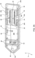
Figure 3A is a top transparent perspective view of a base of the sensor assembly shown inFigure 1 , illustrating fluid passageways connecting the first and second sensor substrates; -
Figure 3B is a bottom transparent perspective view of the base shown inFigure 3A ; -
Figure 4A is a top perspective view of a sensor assembly according to another embodiment of the present disclosure; -
Figure 4B is a bottom perspective view of the sensor assembly shown inFigure 4A ; -
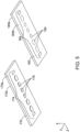
Figure 5 is a perspective view of the first sensor substrate and the second sensor substrates of the sensor assembly shown inFigure 4A ; -
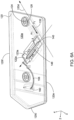
Figure 6A is a top transparent perspective view of a base of the sensor assembly shown inFigure 4A ; -
Figure 6B is a bottom transparent perspective view of the sensor assembly shown inFigure 6A ; -
Figure 7A is a side schematic sectional view of a sensor assembly according to another embodiment of the present disclosure; -
Figure 7B is a cross-sectional view of the sensor assembly shown inFigure 7A , taken alongline 7B-7B inFigure 7A ; -
Figure 8A is a top schematic view of a sensor assembly according to another embodiment of the present disclosure; and -
Figure 8B is a side schematic sectional view of the sensor assembly shown inFigure 8A . - Certain terminology is used to describe the
sensor assemblies sensor assemblies longitudinal direction 2 and a direction opposite thelongitudinal direction 2 along thesensor assemblies - Unless otherwise specified herein, the terms "longitudinal," "lateral," and "vertical" are used to describe the orthogonal directional components of various components of the
sensor assemblies longitudinal direction 2,lateral direction 3, andvertical direction 4. It should be appreciated that while the longitudinal andlateral directions vertical direction 4 is illustrated as extending along a vertical plane, the planes that encompass the various directions may differ during use. -
Figures 1-3B depict a first embodiment of asensor assembly 10 for receiving and testing a sample fluid in a sample fluid analysis system.Figure 1 shows a perspective view of thesensor assembly 10 in a fully assembled configuration. Thesensor assembly 10 includes afirst sensor substrate 70, asecond sensor substrate 80, and abase 20 configured to receive the first andsecond sensor substrates base 20 may define a plurality of fluidic passageways for receiving the sample fluid, as will be discussed further below. - Referring to
Figures 1 and3A-3B , thebase 20 is configured to hold the sensor substrates in an offset configuration with respect to each other. As is known in to one of skill in the art, thebase 20 is configured to be incorporated into a sample analysis system (not shown) for testing, analyzing, and displaying various aspects of the sample fluid. As shown, thebase 20 has anupper surface 20a, alower surface 20b opposite theupper surface 20a along thevertical direction 4, afront end 20c, arear end 20d opposite thefront end 20c along thelongitudinal direction 2, afirst side 20e, and asecond side 20f opposite thefirst side 20e along thelateral direction 3. In the illustrated embodiment, thebase 20 defines a substantially rectangular prism shaped body with thefront end 20c having a forward-facing apex. However, thebase 20 can define other shapes as desired. For instance, thebase 20 can be square, rectangular, oval, or have any other shape that facilitates placement and use with a sample analysis systems. - The
base 20 may include a plurality of recesses for holding thesensor substrates base 20 includes afirst recess 22a that extends from theupper surface 20a into thebase 20 and terminates at a firstinner surface 23a before thelower surface 20b. Thefirst recess 22a is configured to at least partially receive thefirst sensor substrate 70. Thebase 20 also includes asecond recess 22b that extends from theupper surface 20a into thebase 20 and terminates at a secondinner surface 23b before thelower surface 20b. Thesecond recess 22b may at least partially (or completely) receive thesecond sensor substrate 80. In the depicted embodiment, the first andsecond recesses lateral direction 3. The first andsecond recesses lateral direction 3. However, in other embodiments, either of the first andsecond recesses upper surface 20a of thebase 20. Each of the first andsecond recesses second recesses second recesses second sensor substrates upper surface 20a of thebase 20 when the first andsecond sensor substrates second recesses second recesses second sensor substrates base 20 when fully disposed within the first andsecond recesses - Referring to
Figure 2 , the first andsecond sensor substrates first sensor substrate 70 defines anupper surface 70a and alower surface 70b opposite theupper surface 70a along thevertical direction 4. In the illustrated embodiment, thefirst sensor substrate 70 is depicted as a rectangular prism, though other shapes are contemplated. Though each of the upper andlower surfaces lower surfaces first sensor substrate 70 can be configured as a first set ofsensors 74 disposed on itslower surface 70b. The first set ofsensors 74 may include eightsensors 78, each of which can be aligned on thefirst sensor substrate 70 along thelongitudinal direction 2. However, the first set ofsensors 74 can include more or less than eightsensors 78. The arrangement of the second set ofsensors 74 will generally align with the shape of thefirst fluid passage 32, which will be described further below. However, it is contemplated that the first set ofsensors 74 can be arranged differently from what is shown in the figures. Any of thesensors 78 can be a potentiometric sensor for measuring a property of the sample fluid. Alternatively, thesensors 78 can be other types of sensors, such as amperometric, conductometric, thermometric, optical, and piezoelectric sensors. - The
second sensor substrate 80 defines anupper surface 80a and alower surface 80b opposite theupper surface 80a along thevertical direction 4. As shown, thesecond sensor substrate 80 is depicted as defining a rectangular prism, though other shapes are contemplated. Though each of the upper andlower surfaces lower surfaces second sensor substrate 80 may include second set ofsensors 84 disposed on itslower surface 80b. The second set ofsensors 84 may include eightsensors 88, each of which can be aligned on thesecond sensor substrate 80 along thelongitudinal direction 2. However, the second set ofsensors 84 can include more or less than eightsensors 88. The arrangement of the second set ofsensors 84 will generally align with the shape of thesecond fluid passage 48, which will be described further below. However, it is contemplated that the second set ofsensors 84 can be arranged differently than what is explicitly shown. Any of thesensors 88 can be a potentiometric sensor. Alternatively, thesensors 88 can be other types of sensors. For instance, thesensors 88 can be amperometric, conductometric, thermometric, optical, and piezoelectric sensors. Although the first and second sets ofsensors sensors sensors sensors - Each of the first and
second sensor substrates second substrates second sensor substrates second sensor substrates sensors second sensor substrates second sensor substrates sensors first sensor substrate 70 can be attached to the base 20 in thefirst recess 22a with an adhesive. Likewise, thesecond sensor substrate 80 can be attached to the base 20 in thesecond recess 22b with an adhesive. - As shown in
Figure 1 , the first andsecond sensor substrates base 20. In this configuration, the first andsecond sensor substrates lateral direction 3, but aligned along thelateral direction 3, such that no portion of thefirst sensor substrate 70 overlies a portion of thesecond sensor substrate 80. Additionally, the first andsecond sensor substrates - Referring to
Figures 1 and3A-3B , thebase 20 can define a plurality of passages for transporting the sample fluid through thesensor assembly 10. Thebase 20 and passages contained therein can be formed through injection molding, though other procedures are also contemplated. The base 20 can include aninlet 24 located on thelower surface 20b for receiving the sample fluid from another portion of the sample analysis system (not shown). As depicted, theinlet 24 can be located along thelower surface 20b at a position that overlies a portion of thefirst substrate 70 and thefirst recess 22a, such that the flow length of the sample fluid from theinlet 24 to thefirst substrate 70 is minimized. However, it should be understood that theinlet 24 could be located elsewhere along thelower surface 20b, or alternatively along theupper surface 20a. Afirst inlet passage 28 can extend substantially vertically from theinlet 24 to thefirst fluid passage 32, which is the portion of the fluid channel in which the first set ofsensors 74 are exposed to the sample fluid. Thefirst fluid passage 32 is substantially open to thefirst recess 22a and can extend substantially along thelongitudinal direction 2. Thefirst fluid passage 32 can also extend into the base 20 from thefirst recess 22a. For example, thefirst fluid passage 32 can extend from the firstinner surface 23a towards thelower surface 20b and terminate before thelower surface 20b. Thefirst fluid passage 32 can define a length along thelongitudinal direction 2 that is less than a length of thefirst recess 22a along thelongitudinal direction 2. Additionally or alternatively, thefirst fluid passage 32 can define a width along thelateral direction 3 that is less than a width of thefirst recess 22a along thelateral direction 3. In this configuration, when the sample fluid flows through thefirst fluid passage 32, the sample fluid flows along a first flow direction F1 that is substantially parallel to thelongitudinal direction 2. However, thefirst fluid passage 32 and the first flow direction F1 are angularly offset from thelongitudinal direction 2. - Continuing with
Figures 1 and3A-3B , thefirst fluid passage 32 is partially defined by thebase 20 and partially defined by thefirst sensor substrate 70. As shown, the first set ofsensors 74 are exposed to thefirst fluid passage 32 such that the sample fluid flowing through thefirst fluid passage 32 comes into contact with each of thesensors 78 of the first set ofsensors 74. As the first set ofsensors 74 are shown as aligned along thelongitudinal direction 2, the first set ofsensors 74 can be substantially aligned with both thefirst fluid passage 32 and the first flow direction F1. - The
sensor assembly 10 can define a set of passages that transport the sample fluid from thefirst fluid passage 32 to thesecond fluid passage 48 with these passages located downstream from thefirst fluid passage 32. In the depicted embodiment, this includes afirst outlet passage 36 that extends from thefirst fluid passage 32 substantially along thevertical direction 4 to afirst transfer passage 40. Thefirst transfer passage 40, which can extend substantially along thelateral direction 3, extends from thefirst outlet passage 36 to asecond inlet passage 44. Thesecond inlet passage 48 extends substantially along thevertical direction 4 from thefirst transfer passage 44 to thesecond fluid passage 48. Though one particular arrangement of passages is described, it is contemplated that the passages between the first and secondfluid passages - Continuing with
Figures 1 and3A-3B , thesecond fluid passage 48 is located downstream from and in series with thefirst fluid passage 32. Thesecond fluid passage 48 is substantially open to thesecond recess 22b. Thesecond fluid passage 48 can extend substantially along thelongitudinal direction 2. Thesecond fluid passage 48 can also extend into the base 20 from thesecond recess 22b. For example, thesecond fluid passage 48 can extend from the secondinner surface 23b towards thelower surface 20b and terminate before thelower surface 20b. Thesecond fluid passage 48 can define a length along thelongitudinal direction 2 that is less than a length of thesecond recess 22b along thelongitudinal direction 2. Additionally or alternatively, thesecond fluid passage 48 can have a width along thelateral direction 3 that is less than a width of thesecond recess 22b along thelateral direction 3. In this configuration, when the sample fluid flows through thesecond fluid passage 48, the sample fluid flows along a second flow direction F2 that is substantially parallel to thelongitudinal direction 2 and opposite the first flow direction F1. However, it is contemplated that thesecond fluid passage 48 can be differently designed, such that thesecond fluid passage 48 and the second flow direction F2 are angularly offset from thelongitudinal direction 2, and thus the second flow direction F2 is not opposite the first flow direction F1. - As shown, the
second fluid passage 48 is partially defined by thebase 20 and partially defined by thesecond sensor substrate 80. As a result, the first set ofsensors 84 are exposed to thesecond fluid passage 48 such that the sample fluid flowing through thesecond fluid passage 48 comes into contact with each of thesensors 88 of the second set ofsensors 84. As the second set ofsensors 84 are shown as aligned along thelongitudinal direction 2, the second set ofsensors 84 can be substantially aligned with both thesecond fluid passage 48 and the second flow direction F2. - The base 20 can include a
second transfer passage 56 that extends from thesecond fluid passage 48 to theoutlet 60. Theoutlet 60 is configured to emit the sample fluid back to the sample analysis system for disposal. As shown, theoutlet 60 is defined in thelower surface 20b of thebase 20 and can be positioned near thefront end 20c. Theoutlet 60 is positioned so that it does not overlie either of the first orsecond sensor substrates inlet 24, it should be understood that theoutlet 60 could be located elsewhere along thelower surface 20b, or alternatively along theupper surface 20a. - In addition, the
base 20 can further include a plurality ofbores 64 that extend through the base 20 from theupper surface 20a to thelower surface 20b. Each bore 64 can be configured to receive fasteners, such as a screw or a bolt, to releasably or permanently couple thesensor assembly 10 to the sample analysis system. Though thebase 20 is depicted as including twelvebores 64, thebase 20 can alternatively include any number or arrangement ofbores 64 as desired. - Continuing with
Figures 4A-6B , another embodiment of asensor assembly 10a is shown. Thesensor assembly 10a includes afirst sensor substrate 170, asecond sensor substrate 180, and a base 120 configured to receive the first andsecond sensor substrates base 120 defines a plurality of fluidic passageways for receiving the sample fluid, as will be discussed further below. - Referring to
Figures 4A-4B and6A-6B , thebase 120 is configured to hold thesensor substrates base 120 has a similar purpose of functions as the base 20 described above. As shown, thebase 120 has anupper surface 120a, alower surface 120b opposite theupper surface 120a along thevertical direction 4, afront end 120c, arear end 120d opposite thefront end 120c along thelongitudinal direction 2, afirst side 120e, and asecond side 120f opposite thefirst side 120e along thelateral direction 3. In the illustrated embodiment, thebase 120 defines a substantially rectangular prism shaped body with afront end 120c having a forward-facing apex. However, it is contemplated that the base 120 can define other shapes as desired. - The
base 120 includes afirst recess 122a that extends from theupper surface 120a into thebase 120 and terminates at a firstinner surface 123a before thelower surface 120b. Thefirst recess 122a is configured to at least partially receive thefirst sensor substrate 170. The base 120 also includes asecond recess 122b that extends from thelower surface 120b into thebase 120 and terminates at a secondinner surface 123b before theupper surface 120a. Thesecond recess 122a is configured to at least partially receive thesecond sensor substrate 180. In the depicted embodiment, the first andsecond recesses second recesses lateral directions recesses first recess 122a can be sized such that alower surface 170b of thefirst sensor substrate 170 is aligned with thelower surface 120b of the base when thefirst sensor substrate 170 is fully disposed within thefirst recess 122a. Thesecond recess 122b can be sized such that anupper surface 180a of thesecond sensor substrate 180 is aligned with theupper surface 120a of the base when thesecond sensor substrate 180 are fully disposed within thesecond recess 122b. Alternatively, the first andsecond recesses second substrates base 120 when fully disposed within the first andsecond recesses - Referring to
Figure 5 , thefirst sensor substrate 170 defines anupper surface 170a and alower surface 170b opposite theupper surface 170a along thevertical direction 4. As a result, thefirst sensor substrate 170 is depicted as defining a rectangular prism, though other shapes are contemplated. Though each of the upper andlower surfaces lower surface first sensor substrate 170 can be configured to have a first set ofsensors 174 disposed on itsupper surface 170a. The first set ofsensors 174 is depicted as including eightsensors 178, each of which can be aligned on thefirst sensor substrate 170 along thelongitudinal direction 2. However, the first set ofsensors 174 can include more or less than eightsensors 178. Though it is contemplated that the first set ofsensors 174 can be arranged differently, the arrangement of the first set ofsensors 174 will generally align with the shape of thefirst fluid passage 132, which will be described further below. Any of thesensors 178 can be a potentiometric sensor. Alternatively, thesensors 178 can be amperometric, conductometric, thermometric, optical, or piezoelectric sensors. - The
second sensor substrate 180 holds the second set ofsensors 184. As shown, thesecond sensor substrate 180 defines anupper surface 180a and alower surface 180b opposite theupper surface 180a along thevertical direction 4. Thesecond sensor substrate 180 can be configured to have a second set ofsensors 184 disposed on itslower surface 180b. Due to this arrangement, when thesensor assembly 10a is fully assembled, the first and second sets ofsensors sensors 174 face downwardly toward thelower surface 120b of thebase 120 and the second set ofsensors 184 face toward theupper surface 120a of thebase 120. The second set ofsensors 184 is depicted as including eight sensors 188, each of which can be aligned on thesecond sensor substrate 180 along thelongitudinal direction 2. However, the second set ofsensors 184 can include more or less than eight sensors 188. Though it is contemplated that the second set ofsensors 184 can be arranged differently, the arrangement of the second set ofsensors 184 will generally align with the shape of thesecond fluid passage 148, which will be described further below. Like thesensors 178, any of the sensors 188 can be a potentiometric sensor. Alternatively, the sensors 188 can be amperometric, conductometric, thermometric, optical, or piezoelectric sensors. Though depicted as being substantially identical, the first and second sets ofsensors sensors sensors - Each of the first and
second sensor substrates base 120. After thefirst substrate 170 is fully formed and the first sets ofsensors 174, thefirst sensor substrate 170 can be attached to thebase 120 within thefirst recess 122a with an adhesive. Furthermore, thesecond sensor substrate 180 can be attached to thebase 120 within thesecond recess 122b with an adhesive as well. As shown inFigures 4A-4B , the first andsecond sensor substrates base 120. In this configuration, thefirst sensor substrate 170 is positioned along a first axis A1, while thesecond sensor substrate 180 is positioned along a second axis A2 that is angularly offset form the first axis A1 by an angle θ. The orientation of the first and second axes A1, A2, will be described further below. In this configuration, the first andsecond sensor substrates vertical direction 4, such that at least a portion of thefirst sensor substrate 170 is aligned with at least a portion of thesecond sensor substrate 180 along the vertical direction. Further, at least a portion of thefirst sensor substrate 170 can be out of alignment with at least a portion of thesecond sensor substrate 180 along the vertical direction. - Now referring to
Figures 4A-4B and6A-6B , the base 120 can define a plurality of passages for transporting the sample fluid through thesensor assembly 10a. Thebase 120 and passages contained therein can be formed through injection molding, though other procedures are also contemplated. The base 120 can include aninlet 124 located on theupper surface 120a for receiving the sample fluid from another portion of the sample analysis system (not shown). As depicted, the inlet can be located along theupper surface 120a at a position that overlies a portion of thefirst substrate 170 and thefirst recess 122a such that the flow length of the sample fluid from theinlet 124 to thefirst substrate 170 is minimized. However, it should be understood that theinlet 124 could be located elsewhere along theupper surface 120a, or alternatively along thelower surface 120b. Afirst inlet passage 128 can extend substantially vertically from theinlet 124 to thefirst fluid passage 132, which is the portion of the fluid channel in which the first set ofsensors 174 are exposed to the sample fluid. Thefirst fluid passage 132 is substantially open to thefirst recess 122a. For example, thefirst fluid passage 132 can extend from the firstinner surface 123a towards thelower surface 120b and terminate before thelower surface 120b. Thefirst fluid passage 132 can define a length that is less than a length of thefirst recess 122a along the same direction. Additionally or alternatively, thefirst fluid passage 132 can define a width that is less than a width of thefirst recess 122a along the same direction. Thefirst fluid passage 132 can extend substantially along the first axis A1, such that when the sample fluid flows through thefirst fluid passage 132, the sample fluid flows along a first flow direction F1 that is collinear with the first axis A1. - The
first fluid passage 132 may be partially defined by thebase 120 and partially defined by thefirst sensor substrate 170. As a result, the first set ofsensors 174 are exposed to thefirst fluid passage 132 such that the sample fluid flowing through thefirst fluid passage 132 comes into contact with each of thefirst sensors 178 of the first set ofsensors 174 so that thesensors 178 can detect any desired feature of the sample fluid. As the first set ofsensors 174 is shown as aligned along thelongitudinal direction 2, the first set ofsensors 174 can be substantially aligned with thefirst fluid passage 132, the first flow direction F1, and the first axis A1. - Downstream from the
first fluid passage 132, thesensor assembly 10a may include a single passage that transports the sample fluid from thefirst fluid passage 132 to thesecond fluid passage 148. In the depicted embodiment, this includes afirst transfer passage 140 that extends substantially along thevertical direction 4 from thefirst fluid passage 132 to thesecond fluid passage 148. Though one particular passage is shown, it is contemplated that the passages between the first and secondfluid passages - Continuing with
Figures 4A-4B and6A-6B , thesecond fluid passage 148 is located downstream from and in series with thefirst fluid passage 132. Thesecond fluid passage 148 is substantially open to thesecond recess 122b. For example, thesecond fluid passage 148 can extend from the secondinner surface 123b towards theupper surface 120a and terminate before theupper surface 120a. Thesecond fluid passage 148 can define a length that is less than a length of thesecond recess 122b along the same direction. Additionally or alternatively, thesecond fluid passage 148 can define a width that is less than a width of thesecond recess 122b along the same direction. The second fluid passage 148can extend along a second axis A2, such that sample fluid flowing through thesecond fluid passage 148 flows along a second flow direction F2 that is collinear with the second axis A2. The second axis A2 is angularly offset from the first axis A1 by an angle θ. Similarly, the first flow direction F1 is angularly offset form the second flow direction by the angle θ. In the depicted embodiment, the angle θ is about 90 degrees. However, it is contemplated that the first and secondfluid passages - When the
sensor assembly 10a is fully assembled, thesecond fluid passage 148 is partially defined by thebase 120 and partially defined by thesecond sensor substrate 180. As a result, the second set ofsensors 184 are exposed to thesecond fluid passage 148, such that the sample fluid flowing through thesecond fluid passage 148 comes into contact with each of the sensors 188 of the second set of sensors so that the sensors 188 can detect any desired feature of the sample fluid. As the second set ofsensors 184 is shown as aligned along thelongitudinal direction 2, the second set ofsensors 184 can be substantially aligned with thesecond fluid passage 148, the second flow direction F2, and the second axis A2. - Downstream from the
second fluid passage 148, the base 120 can include a series of passages that extends from thesecond fluid passage 148 to theoutlet 160. Theoutlet 160 is configured to emit the sample fluid back to the sample analysis system for disposal. The base 120 can include a vertically-extendingoutlet passage 120 that extends from thesecond fluid passage 148 to asecond transfer passage 156. Thesecond transfer passage 156 can extend from thesecond fluid passage 148 to theoutlet 160 along a curved path. However, though theoutlet passage 120 andsecond transfer passage 156 are shown as directing the sample fluid from thesecond fluid passage 148 to theoutlet 160, more or less passages, or a different arrangement of the passages, are contemplated. Theoutlet 160 is defined in thelower surface 120b of thebase 120 and can be positioned near thefront end 120c. Theoutlet 160 can be positioned so that it does not overlie either of the first orsecond sensor substrates outlet 160 could be located elsewhere along thelower surface 120b or alternatively along theupper surface 120a. - Referring to
Figures 7A-7B , asensor assembly 10b includes features similar tosensor assembly 10a and for that reason the same reference numbers will be used. Insensor assembly 10b, a base 120' is configured to be incorporated into a sample analysis system (not shown) for testing, analyzing, and displaying various aspects of the sample fluid. The base 120' has anupper surface 120a, alower surface 120b opposite theupper surface 120a along thevertical direction 4, afront end 120c, arear end 120d opposite thefront end 120c along thelongitudinal direction 2, afirst side 120e, and asecond side 120f opposite thefirst side 120e along thelateral direction 3. In the illustrated embodiment, the base 120' defines a substantially rectangular prism. However, the base 120' can define other shapes as desired. For instance, thebase 20 can be square, rectangular, oval, or have any other shape that facilitates placement and use with a sample analysis systems. - The base 120' can include a plurality of recesses for holding the
sensor substrates first recess 122a that extends from theupper surface 120a into the base 120' and is configured to at least partially receive thefirst sensor substrate 170. The base 120' also includes asecond recess 122b that extends from thelower surface 120b into the base 120' and is configured to at least partially receive thesecond sensor substrate 180. As a result, the first andsecond sensor substrates second recesses vertical direction 4, such that the first andsecond sensor substrates - As shown in
Figure 7A , the first andsecond recesses second sensor substrates second recesses front end 120c and therear end 120d. Similarly, as shown inFigure 7B , the first andsecond recesses second sensor substrates second recesses first side 120e and thesecond side 120f. - The base 120' can further include first and second
fluid passages first fluid passage 132 is open to thefirst recess 122a and thesecond fluid passage 148 is open to thesecond recess 122b. Thefirst fluid passage 132 defines the area of the base 120' where eachsensor 178 of the set ofsensors 174 is exposed to the sample fluid, and thesecond fluid passage 148 defines the area of the base 120' where eachsensor 180 of the second set ofsensors 184 is exposed to the sample fluid. Like therecesses substrates fluid passages fluid passages vertical direction 4. Thefirst fluid passage 132 can extend into the base 120' from thefirst recess 122a. For example, thefirst fluid passage 132 can extend from the firstinner surface 123a towards thelower surface 120b and terminate before thelower surface 120b. Further, thefirst fluid passage 132 can define a length along thelongitudinal direction 2 that is less than a length of thefirst recess 122a along thelongitudinal direction 2. Additionally or alternatively, thefirst fluid passage 132 can define a width along thelateral direction 3 that is less than a width of thefirst recess 122a along thelateral direction 3. Thesecond fluid passage 148 can extend into the base 120' from thesecond recess 122b. For example, thesecond fluid passage 148 can extend from the secondinner surface 123b towards theupper surface 120a and terminate before theupper surface 120a. Thesecond fluid passage 148 can define a length along thelongitudinal direction 2 that is less than a length of thesecond recess 122b along thelongitudinal direction 2. Additionally or alternatively, thesecond fluid passage 148 can define a width along thelateral direction 3 that is less than a width of thesecond recess 122b along thelateral direction 3. Thefirst fluid passage 132 can extend along a first axis A1 and thesecond fluid passage 148 can extend along a second axis A2, where the first and second axes A1, A2 are substantially parallel to each other. In one embodiment, the first and second axes A1, A2 can each extend along thelongitudinal direction 2. The direction of fluid flow within the first and secondfluid passages sensor assembly 10b can be substantially opposite each other. - Referring to
Figures 8A and 8B , asensor assembly 10c will be described. Where thesensor assembly 10c includes like features tosensor assembly 10a, the same reference numbers will be used. Insensor assembly 10c, the first andsecond sensor substrates second sensor substrates longitudinal direction 2 and substantially aligned along thelongitudinal direction 2. Similarly, the first and secondfluid passages longitudinal direction 2 and substantially aligned along thelongitudinal direction 2. The direction of fluid flow within the first and secondfluid passages sensor assembly 10c can be substantially the same. -
Sensor assemblies sensor assemblies sensor assemblies - The invention includes the following illustrative embodiments:
- Embodiment 1 is a sensor assembly. The sensor assembly includes a first sensor substrate having an upper surface, a lower surface opposite the upper surface, and a first set of sensors disposed along the lower surface of the first sensor substrate. The sensor assembly includes a second sensor substrate having an upper surface, a lower surface opposite the upper surface, and a second set of sensors disposed along the lower surface of the second sensor substrate. The sensor assembly includes a base. The base has an upper surface, a lower surface opposite the upper surface of the base along a vertical direction, and a front end. The base has a rear end opposite the front end along a longitudinal direction that is perpendicular to the vertical direction, a first recess that extends from the upper surface of the base and at least partially holds the first sensor substrate, and a second recess that extends from the upper surface of the base and at least partially holds the second sensor substrate. The base has a first fluid passage for receiving a fluid and a second fluid passage in series with and open to the first fluid passage. The first set of sensors is exposed to the first fluid passage, and the second set of sensors is exposed to the second fluid passage.
-
Embodiment 2 is the sensor assembly according to embodiment 1, wherein the first and second fluid passages extend along the longitudinal direction, such that the fluid flows through the first fluid passage in a first flow direction through the second fluid passage in a second flow direction that is opposite the first flow direction. -
Embodiment 3 is the sensor assembly according to embodiment 1, wherein the first and second sensor substrates are spaced apart along a lateral direction that is perpendicular to the longitudinal direction. -
Embodiment 4 is the sensor assembly according toembodiment 3, wherein the first recess and the second recess are each substantially aligned along the lateral direction. - Embodiment 5 is the sensor assembly of according to
embodiment 3, further comprising a transfer passage that extends from the first fluid passage to the second fluid passage substantially along the lateral direction. - Embodiment 6 is the sensor assembly according to embodiment 1, wherein the first and second sensor substrates are positioned substantially parallel to each other.
-
Embodiment 7 is the sensor assembly according to embodiment 1, wherein the first fluid passage is partially defined by each of the body of the base and the first sensor substrate, and the second fluid passage is partially defined by each of the body of the base and the second sensor substrate. - Embodiment 8 is the sensor assembly according to embodiment 1, wherein lower surface of the base defines an inlet for receiving the fluid and an outlet for emitting the fluid.
- Embodiment 9 is the sensor assembly according to embodiment 1, wherein one of the first and second sets of sensors comprises potentiometric sensors, and the other of the first and second sets of sensors comprises other types sensors.
-
Embodiment 10 is a sensor assembly. The sensor assembly includes a first sensor substrate having an upper surface, a lower surface opposite the upper surface, and a first set of sensors disposed on the lower surface of the first sensor substrate. The sensor assembly includes a second sensor substrate defining an upper surface, a lower surface opposite the upper surface, and a second set of sensors disposed on the upper surface of the second sensor substrate. The sensor assembly includes a base. The base has an upper surface, a lower surface opposite the upper surface of the base along a vertical direction, and a front end. The base has a rear end opposite the front end along a longitudinal direction that is perpendicular to the vertical direction, a first recess that extends from the upper surface of the base and at least partially holds the first sensor substrate, and a second recess that extends from the lower surface of the base and at least partially holds the second sensor substrate. The base has a first fluid passage for receiving a fluid, and a second fluid passage in series with and open to the first fluid passage. The first set of sensors is exposed to the first fluid passage, and the second set of sensors is exposed to the second fluid passage. - Embodiment 11 is the sensor assembly according to
embodiment 10, wherein the first sensor passage extends along a first axis and the second sensor passage extends along a second axis that is offset from the first axis by an angle. - Embodiment 12 is the sensor assembly according to embodiment 11, wherein the angle is about 90 degrees.
- Embodiment 13 is the sensor assembly according to embodiment 11, wherein the angle is about 180 degrees.
- Embodiment 14 is the sensor assembly according to
embodiment 10, wherein the fluid flows through the first fluid passage in a first flow direction and the fluid flows through the second fluid passage in a second flow direction that is opposite the first flow direction. - Embodiment 15 is the sensor assembly according to
embodiment 10, the first sensor substrate overlies the second sensor substrate along the vertical direction. - Embodiment 16 is the sensor assembly according to embodiment 15, wherein the first and second sensor substrates are substantially aligned along the vertical direction.
- Embodiment 17 is the sensor assembly according to
embodiment 10, further comprising a transfer passage that extends from the first fluid passage to the second fluid passage, wherein the transfer passage extends substantially along the vertical direction. - Embodiment 18 is the sensor assembly according to
embodiment 10, wherein the first fluid passage is partially defined by each of the base and the first sensor substrate and the second fluid passage is partially defined by each of the base and the second sensor substrate. - Embodiment 19 is the sensor assembly according to
embodiment 10, wherein the upper surface of the base defines an inlet for receiving the fluid, and the lower surface of the base defines an outlet for emitting the fluid. -
Embodiment 20 is the sensor assembly according toembodiment 10, wherein one of the first and second sets of sensors comprises potentiometric sensors, and the other of the first and second sets of sensors comprises other types of sensors. - Those skilled in the art will also appreciate that the present disclosure may be applied to other applications and may be modified without departing from the scope of the present disclosure. Accordingly, the scope of the present disclosure is not intended to be limited to the exemplary embodiments described above, but only by the appended claims.
Claims (11)
- A sensor assembly comprising:a first sensor substrate (70, 170) having an upper surface (70a, 170a), a lower surface (70b, 170b) opposite the upper surface (70a, 170a), and a first set of sensors (74, 174) disposed on the upper surface (70a, 170a) of the first sensor substrate (70, 170);a second sensor substrate (80, 180) defining an upper surface (80a, 180a), a lower surface (80b, 180b) opposite the upper surface (80a, 180a), and a second set of sensors (84, 184) disposed on the lower surface (80b, 180b) of the second sensor substrate (80, 180);a base (20, 120) having a body that defines an upper surface (20a, 120a), a lower surface (20b, 120b) opposite the upper surface (20a, 120a) of the base (20, 120) along a vertical direction (4), a front end (20c, 120c), a rear end (20d, 120d) opposite the front end (20c, 120c) along a longitudinal direction (2) that is perpendicular to the vertical direction (4), a first recess that extends from the lower surface of the base andat least partially holds the first sensor substrate, a second recess that extends from the upper surface of the base and at least partially holds the second sensor substrate, a first fluid passage for receiving a fluid, and a second fluid passage in series with and open to the first fluid passage,wherein the first set of sensors is exposed to the first fluid passage, and the second set of sensors is exposed to the second fluid passage.
- The sensor assembly of claim 1, the first sensor substrate overlies the second sensor substrate along the vertical direction.
- The sensor assembly of claim 1, wherein the first sensor passage extends along a first axis and the second sensor passage extends along a second axis that is offset from the first axis by an angle.
- The sensor assembly of claim 3, wherein the angle is about 90 degrees.
- The sensor assembly of claim 3, wherein the angle is about 180 degrees.
- The sensor assembly of claim 1, wherein the fluid flows through the first fluid passage in a first flow direction and the fluid flows through the second fluid passage in a second flow direction that is opposite the first flow direction.
- The sensor assembly of claim 6, wherein the first and second sensor substrates are substantially aligned along the vertical direction.
- The sensor assembly of claim 1, further comprising a transfer passage that extends from the first fluid passage to the second fluid passage, wherein the transfer passage extends substantially along the vertical direction.
- The sensor assembly of claim 1, wherein the first fluid passage is partially defined by each of the base and the first sensor substrate and the second fluid passage is partially defined by each of the base and the second sensor substrate.
- The sensor assembly of claim 1, wherein the upper surface of the base defines an inlet for receiving the fluid, and the lower surface of the base defines an outlet for emitting the fluid.
- The sensor assembly of claim 1, wherein one of the first and second sets of sensors comprises potentiometric sensors, and the other of the first and second sets of sensors comprises other types of sensors.
Applications Claiming Priority (3)
| Application Number | Priority Date | Filing Date | Title |
|---|---|---|---|
| US201862692075P | 2018-06-29 | 2018-06-29 | |
| EP19825808.9A EP3814012B1 (en) | 2018-06-29 | 2019-06-20 | Sensor assembly for a sample fluid analysis system |
| PCT/US2019/038170 WO2020005697A1 (en) | 2018-06-29 | 2019-06-20 | Sensor assembly for a sample fluid analysis system |
Related Parent Applications (2)
| Application Number | Title | Priority Date | Filing Date |
|---|---|---|---|
| EP19825808.9A Division-Into EP3814012B1 (en) | 2018-06-29 | 2019-06-20 | Sensor assembly for a sample fluid analysis system |
| EP19825808.9A Division EP3814012B1 (en) | 2018-06-29 | 2019-06-20 | Sensor assembly for a sample fluid analysis system |
Publications (1)
| Publication Number | Publication Date |
|---|---|
| EP4389283A1 true EP4389283A1 (en) | 2024-06-26 |
Family
ID=68985204
Family Applications (2)
| Application Number | Title | Priority Date | Filing Date |
|---|---|---|---|
| EP19825808.9A Active EP3814012B1 (en) | 2018-06-29 | 2019-06-20 | Sensor assembly for a sample fluid analysis system |
| EP24162846.0A Pending EP4389283A1 (en) | 2018-06-29 | 2019-06-20 | Sensor assembly for a sample fluid analysis system |
Family Applications Before (1)
| Application Number | Title | Priority Date | Filing Date |
|---|---|---|---|
| EP19825808.9A Active EP3814012B1 (en) | 2018-06-29 | 2019-06-20 | Sensor assembly for a sample fluid analysis system |
Country Status (7)
| Country | Link |
|---|---|
| US (1) | US11154859B2 (en) |
| EP (2) | EP3814012B1 (en) |
| JP (1) | JP6992199B2 (en) |
| CA (1) | CA3105374C (en) |
| IL (2) | IL279762A (en) |
| MX (1) | MX2020013996A (en) |
| WO (1) | WO2020005697A1 (en) |
Families Citing this family (1)
| Publication number | Priority date | Publication date | Assignee | Title |
|---|---|---|---|---|
| EP4211465A4 (en) * | 2020-09-09 | 2024-02-28 | Siemens Healthcare Diagnostics, Inc. | SENSOR NETWORK |
Citations (5)
| Publication number | Priority date | Publication date | Assignee | Title |
|---|---|---|---|---|
| US20130269419A1 (en) * | 2010-10-28 | 2013-10-17 | Kurt Etherington | Sensor device for detecting a flow property of a fluid medium |
| US20140224002A1 (en) * | 2011-07-28 | 2014-08-14 | Kyocera Coproration | Biosensor |
| WO2016007716A1 (en) * | 2014-07-09 | 2016-01-14 | Siemens Healthcare Diagnostics Inc. | Low sample volume sensing device |
| US20160245793A1 (en) * | 2014-05-31 | 2016-08-25 | Chromedx Corp. | Joint spectroscopic and biosensor system for point-of-care testing |
| US20180104682A1 (en) * | 2015-07-17 | 2018-04-19 | Cue Inc. | Cartridges, kits, and methods for enhanced detection and quantification of analytes |
Family Cites Families (7)
| Publication number | Priority date | Publication date | Assignee | Title |
|---|---|---|---|---|
| US6082185A (en) * | 1997-07-25 | 2000-07-04 | Research International, Inc. | Disposable fluidic circuit cards |
| DE10111458B4 (en) * | 2001-03-09 | 2008-09-11 | Siemens Ag | analyzer |
| JP4613667B2 (en) | 2005-03-31 | 2011-01-19 | セイコーエプソン株式会社 | Liquid detection device, liquid container, and manufacturing method of liquid detection device |
| TW200702201A (en) | 2005-03-31 | 2007-01-16 | Seiko Epson Corp | Liquid detecting device, liquid container and method of manufacturing liquid detecting device |
| JP4884361B2 (en) * | 2007-12-21 | 2012-02-29 | シャープ株式会社 | Chemical reaction equipment using microbeads |
| JP6516990B2 (en) | 2014-09-02 | 2019-05-22 | キヤノンメディカルシステムズ株式会社 | Nucleic acid detection cassette |
| EP3496860A4 (en) | 2016-08-11 | 2020-01-08 | SRI International Inc. | BIOLOGICAL SAMPLES ANALYSIS SYSTEM, COMPONENTS AND RELATED METHODS |
-
2019
- 2019-06-20 WO PCT/US2019/038170 patent/WO2020005697A1/en not_active Ceased
- 2019-06-20 EP EP19825808.9A patent/EP3814012B1/en active Active
- 2019-06-20 US US16/973,962 patent/US11154859B2/en active Active
- 2019-06-20 JP JP2020573122A patent/JP6992199B2/en active Active
- 2019-06-20 CA CA3105374A patent/CA3105374C/en active Active
- 2019-06-20 MX MX2020013996A patent/MX2020013996A/en unknown
- 2019-06-20 EP EP24162846.0A patent/EP4389283A1/en active Pending
-
2020
- 2020-12-24 IL IL279762A patent/IL279762A/en unknown
-
2025
- 2025-10-19 IL IL324058A patent/IL324058A/en unknown
Patent Citations (5)
| Publication number | Priority date | Publication date | Assignee | Title |
|---|---|---|---|---|
| US20130269419A1 (en) * | 2010-10-28 | 2013-10-17 | Kurt Etherington | Sensor device for detecting a flow property of a fluid medium |
| US20140224002A1 (en) * | 2011-07-28 | 2014-08-14 | Kyocera Coproration | Biosensor |
| US20160245793A1 (en) * | 2014-05-31 | 2016-08-25 | Chromedx Corp. | Joint spectroscopic and biosensor system for point-of-care testing |
| WO2016007716A1 (en) * | 2014-07-09 | 2016-01-14 | Siemens Healthcare Diagnostics Inc. | Low sample volume sensing device |
| US20180104682A1 (en) * | 2015-07-17 | 2018-04-19 | Cue Inc. | Cartridges, kits, and methods for enhanced detection and quantification of analytes |
Also Published As
| Publication number | Publication date |
|---|---|
| EP3814012B1 (en) | 2024-04-24 |
| US11154859B2 (en) | 2021-10-26 |
| EP3814012A4 (en) | 2021-11-17 |
| IL324058A (en) | 2025-12-01 |
| US20210121877A1 (en) | 2021-04-29 |
| IL279762A (en) | 2021-03-01 |
| MX2020013996A (en) | 2021-03-25 |
| EP3814012C0 (en) | 2024-04-24 |
| CA3105374A1 (en) | 2020-01-02 |
| JP2021524041A (en) | 2021-09-09 |
| JP6992199B2 (en) | 2022-01-13 |
| WO2020005697A1 (en) | 2020-01-02 |
| EP3814012A1 (en) | 2021-05-05 |
| CA3105374C (en) | 2022-08-23 |
Similar Documents
| Publication | Publication Date | Title |
|---|---|---|
| US7760351B2 (en) | Cytometer having fluid core stream position control | |
| US7223371B2 (en) | Microfluidic channel network device | |
| US4361539A (en) | Analysis system | |
| US4443407A (en) | Analysis system | |
| CN101970112B (en) | Modular sensor cassette | |
| US11231409B2 (en) | Disposable hemolysis sensor | |
| US9462969B2 (en) | Microneedle | |
| ES2285200T3 (en) | PROCEDURE AND DEVICE FOR MAKING BLOOD MEASUREMENTS. | |
| US9354152B2 (en) | Rheometry apparatus | |
| US20100307617A1 (en) | Flow cell | |
| EP2762854B1 (en) | Micro-molded cytometer cartridge with integrated optics | |
| BRPI0609610A2 (en) | optical device for blood analysis, analyzer equipped with the same | |
| CN106471360B (en) | Electrochemical sensor array and equipment | |
| CA3105374C (en) | Sensor assembly for a sample fluid analysis system | |
| US11376586B2 (en) | Sensor cassette | |
| BRPI0609493A2 (en) | method for analyzing a blood sample and apparatus and reagent to implement said method | |
| WO2020132146A1 (en) | Optical analyte detection | |
| US20060073609A1 (en) | Sample supplying method and device | |
| JP2955705B2 (en) | Fluid measurement device | |
| US20100332148A1 (en) | Device and method for measuring fine particle concentration | |
| BRPI0609494A2 (en) | hydraulic device for a blood analyzer, associated method and analyzer equipped with such a device | |
| CN215263539U (en) | Immunoreaction flow cell and immunoreaction system | |
| US10954481B2 (en) | Pillar unit for bio chip | |
| US10132792B2 (en) | Portable diagnostic measurement device for determining at least one analytical parameter of a body fluid | |
| CN102439417B (en) | Modular optical sensor system for fluid media |
Legal Events
| Date | Code | Title | Description |
|---|---|---|---|
| PUAI | Public reference made under article 153(3) epc to a published international application that has entered the european phase |
Free format text: ORIGINAL CODE: 0009012 |
|
| STAA | Information on the status of an ep patent application or granted ep patent |
Free format text: STATUS: THE APPLICATION HAS BEEN PUBLISHED |
|
| AC | Divisional application: reference to earlier application |
Ref document number: 3814012 Country of ref document: EP Kind code of ref document: P |
|
| AK | Designated contracting states |
Kind code of ref document: A1 Designated state(s): AL AT BE BG CH CY CZ DE DK EE ES FI FR GB GR HR HU IE IS IT LI LT LU LV MC MK MT NL NO PL PT RO RS SE SI SK SM TR |
|
| STAA | Information on the status of an ep patent application or granted ep patent |
Free format text: STATUS: REQUEST FOR EXAMINATION WAS MADE |
|
| 17P | Request for examination filed |
Effective date: 20241227 |
|
| GRAP | Despatch of communication of intention to grant a patent |
Free format text: ORIGINAL CODE: EPIDOSNIGR1 |
|
| STAA | Information on the status of an ep patent application or granted ep patent |
Free format text: STATUS: GRANT OF PATENT IS INTENDED |