EP4387388A1 - Method of operating an electrical heating element - Google Patents
Method of operating an electrical heating element Download PDFInfo
- Publication number
- EP4387388A1 EP4387388A1 EP22214184.8A EP22214184A EP4387388A1 EP 4387388 A1 EP4387388 A1 EP 4387388A1 EP 22214184 A EP22214184 A EP 22214184A EP 4387388 A1 EP4387388 A1 EP 4387388A1
- Authority
- EP
- European Patent Office
- Prior art keywords
- voltage
- reference current
- heating element
- current
- ref
- Prior art date
- Legal status (The legal status is an assumption and is not a legal conclusion. Google has not performed a legal analysis and makes no representation as to the accuracy of the status listed.)
- Granted
Links
Images


Classifications
-
- H—ELECTRICITY
- H05—ELECTRIC TECHNIQUES NOT OTHERWISE PROVIDED FOR
- H05B—ELECTRIC HEATING; ELECTRIC LIGHT SOURCES NOT OTHERWISE PROVIDED FOR; CIRCUIT ARRANGEMENTS FOR ELECTRIC LIGHT SOURCES, IN GENERAL
- H05B1/00—Details of electric heating devices
- H05B1/02—Automatic switching arrangements specially adapted to apparatus ; Control of heating devices
- H05B1/0227—Applications
- H05B1/023—Industrial applications
-
- F—MECHANICAL ENGINEERING; LIGHTING; HEATING; WEAPONS; BLASTING
- F03—MACHINES OR ENGINES FOR LIQUIDS; WIND, SPRING, OR WEIGHT MOTORS; PRODUCING MECHANICAL POWER OR A REACTIVE PROPULSIVE THRUST, NOT OTHERWISE PROVIDED FOR
- F03D—WIND MOTORS
- F03D17/00—Monitoring or testing of wind motors, e.g. diagnostics
- F03D17/009—Monitoring or testing of wind motors, e.g. diagnostics characterised by the purpose
- F03D17/021—Monitoring or testing of wind motors, e.g. diagnostics characterised by the purpose for monitoring power or current
-
- F—MECHANICAL ENGINEERING; LIGHTING; HEATING; WEAPONS; BLASTING
- F03—MACHINES OR ENGINES FOR LIQUIDS; WIND, SPRING, OR WEIGHT MOTORS; PRODUCING MECHANICAL POWER OR A REACTIVE PROPULSIVE THRUST, NOT OTHERWISE PROVIDED FOR
- F03D—WIND MOTORS
- F03D80/00—Details, components or accessories not provided for in groups F03D1/00 - F03D17/00
- F03D80/40—Ice detection; De-icing means
- F03D80/401—De-icing by electrical resistance heating
-
- H—ELECTRICITY
- H05—ELECTRIC TECHNIQUES NOT OTHERWISE PROVIDED FOR
- H05B—ELECTRIC HEATING; ELECTRIC LIGHT SOURCES NOT OTHERWISE PROVIDED FOR; CIRCUIT ARRANGEMENTS FOR ELECTRIC LIGHT SOURCES, IN GENERAL
- H05B3/00—Ohmic-resistance heating
- H05B3/10—Heating elements characterised by the composition or nature of the materials or by the arrangement of the conductor
- H05B3/12—Heating elements characterised by the composition or nature of the materials or by the arrangement of the conductor characterised by the composition or nature of the conductive material
- H05B3/14—Heating elements characterised by the composition or nature of the materials or by the arrangement of the conductor characterised by the composition or nature of the conductive material the material being non-metallic
- H05B3/145—Carbon only, e.g. carbon black, graphite
-
- F—MECHANICAL ENGINEERING; LIGHTING; HEATING; WEAPONS; BLASTING
- F03—MACHINES OR ENGINES FOR LIQUIDS; WIND, SPRING, OR WEIGHT MOTORS; PRODUCING MECHANICAL POWER OR A REACTIVE PROPULSIVE THRUST, NOT OTHERWISE PROVIDED FOR
- F03D—WIND MOTORS
- F03D13/00—Assembly, mounting or commissioning of wind motors; Arrangements specially adapted for transporting wind motor components
- F03D13/30—Commissioning, e.g. inspection, testing or final adjustment before releasing for production
-
- H—ELECTRICITY
- H05—ELECTRIC TECHNIQUES NOT OTHERWISE PROVIDED FOR
- H05B—ELECTRIC HEATING; ELECTRIC LIGHT SOURCES NOT OTHERWISE PROVIDED FOR; CIRCUIT ARRANGEMENTS FOR ELECTRIC LIGHT SOURCES, IN GENERAL
- H05B2214/00—Aspects relating to resistive heating, induction heating and heating using microwaves, covered by groups H05B3/00, H05B6/00
- H05B2214/02—Heaters specially designed for de-icing or protection against icing
-
- Y—GENERAL TAGGING OF NEW TECHNOLOGICAL DEVELOPMENTS; GENERAL TAGGING OF CROSS-SECTIONAL TECHNOLOGIES SPANNING OVER SEVERAL SECTIONS OF THE IPC; TECHNICAL SUBJECTS COVERED BY FORMER USPC CROSS-REFERENCE ART COLLECTIONS [XRACs] AND DIGESTS
- Y02—TECHNOLOGIES OR APPLICATIONS FOR MITIGATION OR ADAPTATION AGAINST CLIMATE CHANGE
- Y02E—REDUCTION OF GREENHOUSE GAS [GHG] EMISSIONS, RELATED TO ENERGY GENERATION, TRANSMISSION OR DISTRIBUTION
- Y02E10/00—Energy generation through renewable energy sources
- Y02E10/70—Wind energy
- Y02E10/72—Wind turbines with rotation axis in wind direction
Definitions
- This invention relates to the technical field of wind turbines with rotor blade heating systems.
- Some rotor blade heating systems use electrothermal heating (ohmic resistors) to reduce, avoid or melt ice accretion on the rotor blade surface.
- electrothermal heating electric resistors
- electrical quantities such as electric current and electric voltage can be used.
- the method of operating an electrical heating element of a wind turbine rotor blade comprises the following steps:
- the electrical heating element is mounted to and/or integrated into a wind turbine rotor blade.
- the heating element may include an ohmic resistor, for example at least one layer comprising carbon fibers and/or metal wires.
- the at least one layer is arranged on or close to a surface of the wind turbine rotor blade such that a temperature of the surface can be raised by generating thermal energy by means of a heating current guided through the heating element.
- the thermal power corresponds to the electrical power consumed by the heating element, and will be proportionate to product of the voltage applied to the heating element and the current flowing through the heating element.
- the power and/or surface temperature can be controlled such that the formation of ice on the surface is prevented (anti-icing) and/or such that ice already formed on the surface is melted and/or removed from the surface (de-icing).
- a heating system of a wind turbine typically includes a plurality of heating elements.
- the method can be carried out individually for each of the heating elements.
- the method can be carried out for groups of heating elements, e.g. a voltage applied to a group of heating elements and a current flowing through the group of heating elements can be measured, and a reference current can be calculated for this group of heating elements.
- the group of heating elements may include multiple heating elements connected in series or connected in parallel. For example, there may be one group of heating elements for each rotor blade of the wind turbine, so that a reference current is calculated for each rotor blade. In another example, all of the heating elements of the wind turbine may form a single group.
- a reference current is determined which is based on a measured current flowing through the heating element.
- the measured current will be influenced not only by the properties of the heating element and by the operating conditions such as the ambient temperature, but also by any fluctuations of the voltage applied to the heating element. These fluctuations do not include information on the condition of the heating element. For this reason, it is desired to exclude the influence of the voltage fluctuations on the current.
- a reference current is calculated by applying a normalization factor to the measured current.
- the normalization factor corresponds to the ratio of a nominal voltage to the measured voltage.
- the calculated reference current therefore corresponds to the current that would flow through the heating element if the nominal voltage was applied to the heating element.
- I ref I meas * U nom / U meas
- U ref the reference current
- I meas the measured current
- U nom the nominal voltage of the heating element
- U meas is the measured voltage applied to the heating element.
- U nom /U meas is the normalization factor.
- the first predetermined range may be defined by an upper limit and by a lower limit. It may also be defined as a percentage of a certain, predetermined reference current value. In general, the first predetermined range is defined such that a reference current outside of that range gives reason to take a certain action, which is then triggered.
- the reference current is monitored over time by continuously repeating the steps of measuring the current, measuring the voltage and calculating the reference current. For example, these steps may be repeated in intervals of 1 s, 10 s, 30 s or 1 minute. Changes in the condition of the heating element necessitating a certain action will thus be noticed in a timely manner.
- no reference current is calculated and/or no action is triggered when the measured current is below a predetermined threshold. This may prevent division-by-zero errors.
- no reference current is calculated and/or no action is triggered when the measured voltage is outside a predetermined voltage range. Measuring a voltage outside the predetermined voltage range may indicate problems with a power supply, and should not be misinterpreted as an undue condition of the heating element.
- the step of measuring the voltage includes repeated measurements and determination of an average voltage, wherein in the subsequent step of calculating the reference current, the average voltage is used as the measured voltage. This helps to reduce fluctuations of the calculated reference current based on single extreme measurement values of the voltage.
- the step of measuring a current includes repeated measurements and determination of an average current, wherein in the subsequent step of calculating the reference current, the average current is used as the measured current. This helps to reduce fluctuations of the calculated reference current based on single extreme measurement values of the current.
- the first predetermined reference current range is stored in a control system after having been determined during commissioning of a wind turbine rotor blade heating system which includes the heating element. Determining the first predetermined reference current range during commissioning of the wind turbine rotor blade heating system allows for taking into account individual specifications and manufacturing tolerances, in contrast to using a "standard" reference current range for many rotor blade heating systems.
- the predetermined reference current range can be determined based on a measurement of the electrical resistance of the heating element, and/or based on a certain nominal voltage of the rotor blade heating system.
- the action triggered when the reference current is outside a first predetermined reference current range is selected from the following group of actions: stopping applying a voltage to the heating element, stopping a wind turbine heating system which includes the heating element, stopping the wind turbine, sending a notification, requesting a service team.
- Each of these actions or a combination thereof may be appropriate.
- a wind turbine controller may carry out one or more of these actions, possibly taking into account other data, such as present weather conditions. For example, if the reference current is outside the first predetermined range, it may be required to shut down the wind turbine immediately, in particular when the ambient temperature is very low. On other occasions, it may be sufficient to send a notification and/or to switch off the heating element only.
- the method includes the following additional step:
- the second predetermined reference current range may be wider than the first predetermined reference current range.
- a reference current outside this wider range may imply a severe problem and/or a risk to damage the electrical system. As a consequence, an appropriate action can be taken, in particular switching off the voltage applied to the heating element immediately.
- the above object is also solved by the wind turbine of claim 11.
- the wind turbine comprises a wind turbine rotor blade with an electrical heating element, and a controller adapted to apply a voltage to the heating element, a voltage meter to measure the voltage applied to the heating element, and a current meter to measure a current flowing through the heating element, wherein the controller is adapted to calculate a reference current by applying a normalization factor to the measured current, wherein the normalization factor corresponds to the ratio of a nominal voltage to the measured voltage, and to trigger an action when the reference current is outside a first predetermined reference current range.
- the wind turbine and in particular its controller is adapted to carry out the method of claim 1.
- the controller is further adapted to carry out the method of any of the claims 2 to 10.
- Fig. 1 shows a wind turbine 10 having a tower 12, a nacelle 14, and a wind turbine rotor 16 with a wind turbine rotor hub 18 and three wind turbine rotor blades 20.
- a heating element 22 is arranged on each wind turbine rotor blade 20 such that it covers a leading edge of the respective wind turbine rotor blade 20.
- a controller 24 is arranged in the nacelle 14 and connected to each of the heating elements 22.
- the details of the electrical system are not shown.
- the controller 24, which forms a part of a wind turbine controller is able to apply a voltage to each of the heating elements 22 (for example by closing a switch connecting the heating element 22 or a group of heating elements 22 to a power supply).
- This voltage and a current flowing through each of the heating elements 22 or through a group of heating elements 22 is measured by a voltage meter 23 resp. current meter 25 and the measured values are transferred to the controller 24.
- FIG. 2 illustrates the steps of the method, presuming a voltage has already been applied to a heating element 22.
- step 100 the current I meas flowing through the heating element 22 is measured.
- step 102 the voltage U meas applied to the heating element 22 is measured.
- a reference current I ref is calculated by applying a normalization factor to the measured current I meas , wherein the normalization factor corresponds to the ratio of a nominal voltage U nom to the measured voltage U meas .
- step 106 it is determined whether the calculated reference current I ref is outside a second predetermined reference current range 26 (see Fig. 4 ). If so, the controller 24 in step 108 triggers an action, for example stops the application of voltage to the heating element 22.
- step 110 it is determined whether the calculated reference current I ref is outside a first predetermined reference current range 28 (see Fig. 4 ). If so, the controller 24 in step 112 triggers an action, for example sends a notification including a warning to a service team.
- Figure 3 shows a measured current I meas and a measured voltage U meas over time.
- the measured voltage U meas fluctuates around a nominal voltage U nom , which is mainly due to fluctuations of a supply grid.
- the measured current I meas reflects these fluctuations.
- the reference current I ref calculated as I ref I meas * (U nom /U meas ) is shown as a straight line in the diagram, because it has been corrected for voltage-induced fluctuations.
- Figure 4 illustrates the long-term progression of a reference current I ref of a typical heating element 22.
- a first predetermined current range 28 is defined by an upper limit I ref,warn+ and a lower limit I ref,warn- .
- a second predetermined current range 26 is defined by an upper limit I ref,max and a lower limit I ref,min .
- the reference current I ref gradually decreases due to a slight decrease in the electrical conductivity of the heating element 22.
- the reference current I ref exceeds the lower limit I ref,warn- and is thus outside the first predetermined range 28.
- an action such as a notification send to a service team may be appropriate.
- the reference current I ref exceeds the lower limit I ref,min and is thus outside the second predetermined range 26.
- an action such as stopping to apply a voltage to the heating element 22 or even stopping of the wind turbine 10 may be appropriate.
- Figure 5 illustrates monitoring of a reference current over time.
- the reference current I ref falls below the lower limit I ref,warn- and is thus outside the first predetermined current range 28, indicating a potential incident.
- the reference current I ref falls below the lower limit I ref,min and is thus outside the second predetermined current range 26, indicating a potential loss of electrical connection.
- Fig. 6 illustrates three stages of development, implementation and use of a wind turbine rotor blade heating system.
- the design of the system is determined.
- the nominal voltage U nom and general limits of the electrical system such I ref,max and I ref,min will be determined, so that the first predetermined current range 28 can be defined.
- the wind turbine heating system is commissioned.
- an individual reference current value I ref,com is determined, in particular based on a measurement of the electrical resistance of the heating element 22 or alternatively based on a first measurement of the reference current taken by a power meter and transferred to the controller.
- the commissioner sets this individual reference current value I ref,com as the "center" of the range.
- the upper and lower limits I ref,warn+ and I ref,warn- are calculated by adding/subtracting a fixed percentage, so that the predetermined current range 26 can be defined at this stage.
- the reference current I ref is being monitored with the inventive method, using U meas and I meas to calculate I ref .
Landscapes
- Engineering & Computer Science (AREA)
- Life Sciences & Earth Sciences (AREA)
- Sustainable Development (AREA)
- Sustainable Energy (AREA)
- Chemical & Material Sciences (AREA)
- Combustion & Propulsion (AREA)
- Mechanical Engineering (AREA)
- General Engineering & Computer Science (AREA)
- Wind Motors (AREA)
Abstract
• Applying a voltage to the heating element,
• Measuring a current flowing through the heating element,
• Measuring the voltage applied to the heating element,
• Calculating a reference current by applying a normalization factor to the measured current, wherein the normalization factor corresponds to the ratio of a nominal voltage to the measured voltage,
• Triggering an action when the reference current is outside a first predetermined reference current range.
Description
- This invention relates to the technical field of wind turbines with rotor blade heating systems. Some rotor blade heating systems use electrothermal heating (ohmic resistors) to reduce, avoid or melt ice accretion on the rotor blade surface. To monitor the condition of the heating system, electrical quantities such as electric current and electric voltage can be used.
- It is common practice in such systems to calculate the electrical resistance (voltage divided by current) and monitor this value over time. Changes of the electrical resistance indicate changes of the ambient conditions (e. g. temperature) or of the electrical properties. The latter can be induced by mechanical or electrical damages of the heating system which can be detected by means of the monitoring and actions can be taken accordingly. The document
EP 3436698 B1 describes such monitoring by means of the calculation of electrical resistance values. - Departing therefrom, it is an object of the invention to provide an alternative method of operating an electrical heating element of a wind turbine rotor blade as well as a wind turbine carrying out this method.
- This object is solved by the method of operating an electrical heating element of a wind turbine rotor blade according to claim 1 and by the wind turbine according to claim 11. Advantageous aspects of the invention are given in the dependent claims.
- The method of operating an electrical heating element of a wind turbine rotor blade comprises the following steps:
- Applying a voltage to the heating element,
- Measuring a current flowing through the heating element,
- Measuring the voltage applied to the heating element,
- Calculating a reference current by applying a normalization factor to the measured current, wherein the normalization factor corresponds to the ratio of a nominal voltage to the measured voltage,
- Triggering an action when the reference current is outside a first predetermined reference current range.
- The method including each of its steps can be carried out completely automatically, in particular by an electronic controller such as a wind turbine controller or a wind turbine heating system controller. The steps of the method need not be carried out in the given order, for example the two steps of measuring the voltage and the current, respectively, can be carried out in particular simultaneously or almost simultaneously.
- The electrical heating element is mounted to and/or integrated into a wind turbine rotor blade. The heating element may include an ohmic resistor, for example at least one layer comprising carbon fibers and/or metal wires. The at least one layer is arranged on or close to a surface of the wind turbine rotor blade such that a temperature of the surface can be raised by generating thermal energy by means of a heating current guided through the heating element. The thermal power corresponds to the electrical power consumed by the heating element, and will be proportionate to product of the voltage applied to the heating element and the current flowing through the heating element. Depending on the operating scheme, the power and/or surface temperature can be controlled such that the formation of ice on the surface is prevented (anti-icing) and/or such that ice already formed on the surface is melted and/or removed from the surface (de-icing).
- Of course, a heating system of a wind turbine typically includes a plurality of heating elements. The method can be carried out individually for each of the heating elements. In the alternative, the method can be carried out for groups of heating elements, e.g. a voltage applied to a group of heating elements and a current flowing through the group of heating elements can be measured, and a reference current can be calculated for this group of heating elements. The group of heating elements may include multiple heating elements connected in series or connected in parallel. For example, there may be one group of heating elements for each rotor blade of the wind turbine, so that a reference current is calculated for each rotor blade. In another example, all of the heating elements of the wind turbine may form a single group.
- In accordance with the inventive method, a reference current is determined which is based on a measured current flowing through the heating element. However, the measured current will be influenced not only by the properties of the heating element and by the operating conditions such as the ambient temperature, but also by any fluctuations of the voltage applied to the heating element. These fluctuations do not include information on the condition of the heating element. For this reason, it is desired to exclude the influence of the voltage fluctuations on the current. In order to do so, a reference current is calculated by applying a normalization factor to the measured current. The normalization factor corresponds to the ratio of a nominal voltage to the measured voltage. The calculated reference current therefore corresponds to the current that would flow through the heating element if the nominal voltage was applied to the heating element.
- In other word, the reference current can be calculated as follows:

- After having calculated the reference current, it is determined whether the reference current is outside a first predetermined range. If so, the controller triggers an action. The first predetermined range may be defined by an upper limit and by a lower limit. It may also be defined as a percentage of a certain, predetermined reference current value. In general, the first predetermined range is defined such that a reference current outside of that range gives reason to take a certain action, which is then triggered.
- The invention provides an easy solution to monitor the condition of a heating element based on a simple measurement of the current flowing through the heating element. By applying the normalization factor, any influence of random voltage fluctuations in a supply grid, for example, are excluded, so that meaningful information on the condition of the heating element is obtained.
- In an aspect, the reference current is monitored over time by continuously repeating the steps of measuring the current, measuring the voltage and calculating the reference current. For example, these steps may be repeated in intervals of 1 s, 10 s, 30 s or 1 minute. Changes in the condition of the heating element necessitating a certain action will thus be noticed in a timely manner.
- In an aspect, no reference current is calculated and/or no action is triggered before the voltage has been applied to the heating element for a predetermined time. This ensures that artifacts occurring in the moment of switching will not be misinterpreted as necessitating a certain action.
- In an aspect, no reference current is calculated and/or no action is triggered when the measured current is below a predetermined threshold. This may prevent division-by-zero errors.
- In an aspect, no reference current is calculated and/or no action is triggered when the measured voltage is outside a predetermined voltage range. Measuring a voltage outside the predetermined voltage range may indicate problems with a power supply, and should not be misinterpreted as an undue condition of the heating element.
- In an aspect, the step of measuring the voltage includes repeated measurements and determination of an average voltage, wherein in the subsequent step of calculating the reference current, the average voltage is used as the measured voltage. This helps to reduce fluctuations of the calculated reference current based on single extreme measurement values of the voltage.
- In an aspect, the step of measuring a current includes repeated measurements and determination of an average current, wherein in the subsequent step of calculating the reference current, the average current is used as the measured current. This helps to reduce fluctuations of the calculated reference current based on single extreme measurement values of the current.
- In an aspect, the first predetermined reference current range is stored in a control system after having been determined during commissioning of a wind turbine rotor blade heating system which includes the heating element. Determining the first predetermined reference current range during commissioning of the wind turbine rotor blade heating system allows for taking into account individual specifications and manufacturing tolerances, in contrast to using a "standard" reference current range for many rotor blade heating systems. For example, the predetermined reference current range can be determined based on a measurement of the electrical resistance of the heating element, and/or based on a certain nominal voltage of the rotor blade heating system.
- In an aspect, the action triggered when the reference current is outside a first predetermined reference current range is selected from the following group of actions: stopping applying a voltage to the heating element, stopping a wind turbine heating system which includes the heating element, stopping the wind turbine, sending a notification, requesting a service team. Each of these actions or a combination thereof may be appropriate. A wind turbine controller may carry out one or more of these actions, possibly taking into account other data, such as present weather conditions. For example, if the reference current is outside the first predetermined range, it may be required to shut down the wind turbine immediately, in particular when the ambient temperature is very low. On other occasions, it may be sufficient to send a notification and/or to switch off the heating element only.
- In an aspect, the method includes the following additional step:
- Triggering an action when the reference current is outside a second predetermined reference current range that is defined by general limitations of an electrical supply system.
- The second predetermined reference current range may be wider than the first predetermined reference current range. A reference current outside this wider range may imply a severe problem and/or a risk to damage the electrical system. As a consequence, an appropriate action can be taken, in particular switching off the voltage applied to the heating element immediately.
- The above object is also solved by the wind turbine of claim 11. The wind turbine comprises a wind turbine rotor blade with an electrical heating element, and a controller adapted to apply a voltage to the heating element, a voltage meter to measure the voltage applied to the heating element, and a current meter to measure a current flowing through the heating element, wherein the controller is adapted to calculate a reference current by applying a normalization factor to the measured current, wherein the normalization factor corresponds to the ratio of a nominal voltage to the measured voltage, and to trigger an action when the reference current is outside a first predetermined reference current range. The wind turbine and in particular its controller is adapted to carry out the method of claim 1. In an aspect, the controller is further adapted to carry out the method of any of the claims 2 to 10. With regard to the features and advantages of the wind turbine, reference is made to the above explanations of the related method, which apply to the wind turbine in a corresponding manner.
- In the following, the invention is explained in greater detail based on an embodiment shown in figures. The figures show:
- Fig. 1
- a schematic illustration of a wind turbine;
- Fig. 2
- a flow diagram illustrating the inventive method;
- Fig. 3
- a diagram showing voltage and current measured over time;
- Fig. 4
- a diagram illustrating the long-term progression of a reference current of a typical heating element;
- Fig. 5
- a diagram illustrating monitoring of a reference current over time;
- Fig. 6
- development and implementation stages of a wind turbine rotor blade heating system.
-
Fig. 1 shows awind turbine 10 having atower 12, anacelle 14, and awind turbine rotor 16 with a windturbine rotor hub 18 and three windturbine rotor blades 20. Aheating element 22 is arranged on each windturbine rotor blade 20 such that it covers a leading edge of the respective windturbine rotor blade 20. - A
controller 24 is arranged in thenacelle 14 and connected to each of theheating elements 22. The details of the electrical system are not shown. However, thecontroller 24, which forms a part of a wind turbine controller, is able to apply a voltage to each of the heating elements 22 (for example by closing a switch connecting theheating element 22 or a group ofheating elements 22 to a power supply). This voltage and a current flowing through each of theheating elements 22 or through a group ofheating elements 22 is measured by avoltage meter 23 resp.current meter 25 and the measured values are transferred to thecontroller 24. -
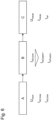
Figure 2 illustrates the steps of the method, presuming a voltage has already been applied to aheating element 22. Instep 100, the current Imeas flowing through theheating element 22 is measured. Instep 102, the voltage Umeas applied to theheating element 22 is measured. - In
step 104, a reference current Iref is calculated by applying a normalization factor to the measured current Imeas, wherein the normalization factor corresponds to the ratio of a nominal voltage Unom to the measured voltage Umeas. - In
step 106, it is determined whether the calculated reference current Iref is outside a second predetermined reference current range 26 (seeFig. 4 ). If so, thecontroller 24 instep 108 triggers an action, for example stops the application of voltage to theheating element 22. - In
step 110, it is determined whether the calculated reference current Iref is outside a first predetermined reference current range 28 (seeFig. 4 ). If so, thecontroller 24 instep 112 triggers an action, for example sends a notification including a warning to a service team. -
Figure 3 shows a measured current Imeas and a measured voltage Umeas over time. One can see the measured voltage Umeas fluctuates around a nominal voltage Unom, which is mainly due to fluctuations of a supply grid. The measured current Imeas reflects these fluctuations. The reference current Iref calculated as Iref = Imeas * (Unom/Umeas) is shown as a straight line in the diagram, because it has been corrected for voltage-induced fluctuations. -
Figure 4 illustrates the long-term progression of a reference current Iref of atypical heating element 22. A first predeterminedcurrent range 28 is defined by an upper limit Iref,warn+ and a lower limit Iref,warn-. A second predeterminedcurrent range 26 is defined by an upper limit Iref,max and a lower limit Iref,min. - The reference current Iref at t = 0 starts at a value of Iref,com, which is determined when commissioning the wind turbine heating system. The reference current Iref gradually decreases due to a slight decrease in the electrical conductivity of the
heating element 22. After several years, at t = t1, the reference current Iref exceeds the lower limit Iref,warn- and is thus outside the firstpredetermined range 28. At this point in time, an action such as a notification send to a service team may be appropriate. - Later, at t = t2, the reference current Iref exceeds the lower limit Iref,min and is thus outside the second
predetermined range 26. At this point in time, an action such as stopping to apply a voltage to theheating element 22 or even stopping of thewind turbine 10 may be appropriate. -
Figure 5 illustrates monitoring of a reference current over time. At t = t3, the reference current Iref falls below the lower limit Iref,warn- and is thus outside the first predeterminedcurrent range 28, indicating a potential incident. At t = t4, the reference current Iref falls below the lower limit Iref,min and is thus outside the second predeterminedcurrent range 26, indicating a potential loss of electrical connection. -
Fig. 6 illustrates three stages of development, implementation and use of a wind turbine rotor blade heating system. In the first stage A (system design), the design of the system is determined. At this stage, the nominal voltage Unom and general limits of the electrical system such Iref,max and Iref,min will be determined, so that the first predeterminedcurrent range 28 can be defined. - In the second stage B (commissioning), the wind turbine heating system is commissioned. At this stage, an individual reference current value Iref,com is determined, in particular based on a measurement of the electrical resistance of the
heating element 22 or alternatively based on a first measurement of the reference current taken by a power meter and transferred to the controller. The commissioner sets this individual reference current value Iref,com as the "center" of the range. The upper and lower limits Iref,warn+ and Iref,warn- are calculated by adding/subtracting a fixed percentage, so that the predeterminedcurrent range 26 can be defined at this stage. - In the third stage C (monitoring), the reference current Iref is being monitored with the inventive method, using Umeas and Imeas to calculate Iref.
-
- 10
- wind turbine
- 12
- tower
- 14
- nacelle
- 16
- wind turbine rotor
- 18
- wind turbine rotor hub
- 20
- wind turbine rotor blade
- 22
- heating element
- 23
- voltage meter
- 24
- controller
- 25
- current meter
- 26
- second predetermined reference current range
- 28
- first predetermined current range
Claims (12)
- A method of operating an electrical heating element (22) of a wind turbine rotor blade (20), the method comprising the following steps:● Applying a voltage to the heating element (22),● Measuring a current flowing through the heating element (22),● Measuring the voltage applied to the heating element (22),● Calculating a reference current (Iref) by applying a normalization factor to the measured current (Imeas), wherein the normalization factor corresponds to the ratio of a nominal voltage (Unom) to the measured voltage (Umeas),● Triggering an action when the reference current (Iref) is outside a first predetermined reference current range (28).
- The method of claim 1, wherein the reference current (Iref) is monitored over time by continuously repeating the steps of measuring the current (Imeas), measuring the voltage (Umeas), and calculating the reference current (Iref).
- The method of claim 1 or 2, wherein no reference current (Iref) is calculated and/or no action is triggered before the voltage has been applied to the heating element (22) for a predetermined time.
- The method of any of the claims 1 to 3, wherein no reference current (Iref) is calculated and/or no action is triggered when the measured current (Imeas) is below a predetermined threshold.
- The method of any of the claims 1 to 4, wherein no reference current (Iref) is calculated and/or no action is triggered when the measured voltage (Umeas) is outside a predetermined voltage range.
- The method of any of the claims 1 to 5, wherein the step of measuring the voltage includes repeated measurements and determination of an average voltage, wherein in the subsequent step of calculating the reference current (Iref), the average voltage is used as the measured voltage (Umeas).
- The method of any of the claims 1 to 6, wherein the step of measuring a current (Imeas) includes repeated measurements and determination of an average current, wherein in the subsequent step of calculating the reference current (Iref), the average current is used as the measured current (Imeas).
- The method of any of the claims 1 to 7, wherein the first predetermined reference current range (28) is stored in a control system after having been determined during commissioning of a wind turbine rotor blade heating system which includes the heating element (22).
- The method of any of the claims 1 to 8, wherein the action triggered when the reference current (Iref) is outside a first predetermined reference current range (28) is selected from the following group of actions: stopping applying a voltage to the heating element (22), stopping a wind turbine heating system which includes the heating element (22), stopping the wind turbine, sending a notification, requesting a service team.
- The method of any of the claims 1 to 9, wherein the method includes the following additional step:● Triggering an action when the reference current (Iref) is outside a second predetermined reference current range (26) that is defined by general limitations of an electrical supply system.
- A wind turbine (10) comprising a wind turbine rotor blade (20) with an electrical heating element (22), and a controller (24) adapted to apply a voltage to the heating element (22), a current meter (25) to measure a current (Imeas) flowing through the heating element (22), and a voltage meter (23) to measure the voltage (Umeas) applied to the heating element (22), characterized in that the controller is adapted to calculate a reference current (Iref) by applying a normalization factor to the measured current (Imeas), wherein the normalization factor corresponds to the ratio of a nominal voltage (Unom) to the measured voltage (Umeas), and to trigger an action when the reference current (Iref) is outside a first predetermined reference current range (28).
- The wind turbine (10) of claim 11, characterized in that the controller (24) is further adapted to carry out the method of any of the claims 2 to 10.
Priority Applications (6)
| Application Number | Priority Date | Filing Date | Title |
|---|---|---|---|
| DK22214184.8T DK4387388T3 (en) | 2022-12-16 | 2022-12-16 | METHOD FOR OPERATING AN ELECTRIC HEATING ELEMENT |
| EP22214184.8A EP4387388B1 (en) | 2022-12-16 | 2022-12-16 | Method of operating an electrical heating element |
| ES22214184T ES3049582T3 (en) | 2022-12-16 | 2022-12-16 | Method of operating an electrical heating element |
| FIEP22214184.8T FI4387388T3 (en) | 2022-12-16 | 2022-12-16 | METHOD FOR USING AN ELECTRICAL HEATING ELEMENT |
| CA3218958A CA3218958A1 (en) | 2022-12-16 | 2023-11-06 | A method of operating an electrical heating element |
| US18/513,195 US12180932B2 (en) | 2022-12-16 | 2023-11-17 | Method of operating an electrical heating element |
Applications Claiming Priority (1)
| Application Number | Priority Date | Filing Date | Title |
|---|---|---|---|
| EP22214184.8A EP4387388B1 (en) | 2022-12-16 | 2022-12-16 | Method of operating an electrical heating element |
Publications (2)
| Publication Number | Publication Date |
|---|---|
| EP4387388A1 true EP4387388A1 (en) | 2024-06-19 |
| EP4387388B1 EP4387388B1 (en) | 2025-07-30 |
Family
ID=84537743
Family Applications (1)
| Application Number | Title | Priority Date | Filing Date |
|---|---|---|---|
| EP22214184.8A Active EP4387388B1 (en) | 2022-12-16 | 2022-12-16 | Method of operating an electrical heating element |
Country Status (6)
| Country | Link |
|---|---|
| US (1) | US12180932B2 (en) |
| EP (1) | EP4387388B1 (en) |
| CA (1) | CA3218958A1 (en) |
| DK (1) | DK4387388T3 (en) |
| ES (1) | ES3049582T3 (en) |
| FI (1) | FI4387388T3 (en) |
Citations (4)
| Publication number | Priority date | Publication date | Assignee | Title |
|---|---|---|---|---|
| US20030178412A1 (en) * | 2002-03-19 | 2003-09-25 | Joshua Goldberg | Propeller de-icing system |
| EP3436698B1 (en) | 2016-03-31 | 2020-01-22 | Vestas Wind Systems A/S | Condition monitoring and controlling of heating elements in wind turbines |
| EP3919740A1 (en) * | 2020-06-04 | 2021-12-08 | Nordex Energy SE & Co. KG | Method of monitoring and controlling a condition of a wind turbine rotor blade, wind turbine and computer readable storage medium |
| US20220074392A1 (en) * | 2018-12-20 | 2022-03-10 | Vestas Wind Systems A/S | Improvements relating to wind turbine blade anti-ice systems |
Family Cites Families (6)
| Publication number | Priority date | Publication date | Assignee | Title |
|---|---|---|---|---|
| DE3437304A1 (en) * | 1984-10-11 | 1986-04-17 | Licentia Patent-Verwaltungs-Gmbh, 6000 Frankfurt | METHOD FOR DETERMINING THE TEMPERATURE, PREFERABLY THE ICE INTERFACE TEMPERATURE, AN ELECTRICAL RESISTANCE HEATING ELEMENT OF A DEFROSTING SYSTEM FOR PLANES, HELICOPTERS OR THE LIKE |
| WO2019001669A1 (en) * | 2017-06-30 | 2019-01-03 | Vestas Wind Systems A/S | Improved electro-thermal heating system for wind turbine blades |
| CA3123700A1 (en) * | 2018-12-20 | 2020-06-25 | Vestas Wind Systems A/S | Improvements relating to wind turbine blade anti-ice systems |
| CN111963393B (en) * | 2019-05-20 | 2022-09-13 | 江苏金风科技有限公司 | Blade electric heating device, blade, wind generating set and blade ice melting method |
| DK4102066T3 (en) * | 2021-06-09 | 2024-05-27 | General Electric Renovables Espana Sl | A WIND TURBINE AND A METHOD FOR LOCATING AN EVENT CORRESPONDING TO A FAILURE OF A HEATING ELEMENT AT A WIND TURBINE BLADE |
| US11952985B2 (en) * | 2022-06-16 | 2024-04-09 | Vestas Wind Systems A/S | Method for operating a cluster of wind turbines |
-
2022
- 2022-12-16 ES ES22214184T patent/ES3049582T3/en active Active
- 2022-12-16 DK DK22214184.8T patent/DK4387388T3/en active
- 2022-12-16 EP EP22214184.8A patent/EP4387388B1/en active Active
- 2022-12-16 FI FIEP22214184.8T patent/FI4387388T3/en active
-
2023
- 2023-11-06 CA CA3218958A patent/CA3218958A1/en active Pending
- 2023-11-17 US US18/513,195 patent/US12180932B2/en active Active
Patent Citations (4)
| Publication number | Priority date | Publication date | Assignee | Title |
|---|---|---|---|---|
| US20030178412A1 (en) * | 2002-03-19 | 2003-09-25 | Joshua Goldberg | Propeller de-icing system |
| EP3436698B1 (en) | 2016-03-31 | 2020-01-22 | Vestas Wind Systems A/S | Condition monitoring and controlling of heating elements in wind turbines |
| US20220074392A1 (en) * | 2018-12-20 | 2022-03-10 | Vestas Wind Systems A/S | Improvements relating to wind turbine blade anti-ice systems |
| EP3919740A1 (en) * | 2020-06-04 | 2021-12-08 | Nordex Energy SE & Co. KG | Method of monitoring and controlling a condition of a wind turbine rotor blade, wind turbine and computer readable storage medium |
Also Published As
| Publication number | Publication date |
|---|---|
| ES3049582T3 (en) | 2025-12-17 |
| FI4387388T3 (en) | 2025-10-21 |
| DK4387388T3 (en) | 2025-10-13 |
| CA3218958A1 (en) | 2024-06-16 |
| US20240200537A1 (en) | 2024-06-20 |
| EP4387388B1 (en) | 2025-07-30 |
| US12180932B2 (en) | 2024-12-31 |
Similar Documents
| Publication | Publication Date | Title |
|---|---|---|
| CN113316685B (en) | Improvements relating to wind turbine blade anti-icing systems | |
| US9822762B2 (en) | System and method for operating a wind turbine | |
| CN108884812B (en) | Condition monitoring and control of heating elements in a wind turbine | |
| EP2514969B1 (en) | Monitoring wind turbine performance | |
| CN103608584B (en) | Method for running wind energy plant under ice-formation condition | |
| EP2082132B1 (en) | Method for controlling a cluster of wind turbines connected to a utility grid and wind turbine cluster. | |
| CN113574272B (en) | Method for detecting ice accumulation on a wind energy installation | |
| US20180187648A1 (en) | Wind turbine control based on forecasts | |
| EP3919740B1 (en) | Method of monitoring and controlling a condition of a wind turbine rotor blade, wind turbine and computer readable storage medium | |
| EP3645879B1 (en) | Improved electro-thermal heating system for wind turbine blades | |
| US12253064B2 (en) | Method for controlling boosted power output of a power generating unit | |
| EP4102066B1 (en) | A wind turbine and a method for locating an event corresponding to a failure of a heating element at a wind turbine blade | |
| CN107735568B (en) | Pitch system and method for mobile power supply testing and method for performing same using pitch system | |
| CN110914536B (en) | Methods of Electrical Contact Fault Diagnosis | |
| JP2020002835A (en) | Wind power generator, control method thereof, and wind power generation system | |
| EP4387388B1 (en) | Method of operating an electrical heating element | |
| JP5123132B2 (en) | Wind power display system | |
| CN119948256A (en) | Method for determining the temperature of a heating element of a wind turbine blade | |
| CN109973333A (en) | A kind of wind energy conversion system electrothermal deicing system method of evaluating performance | |
| CN117365836A (en) | Control methods, devices, electronic equipment and storage media for wind turbines | |
| UA121927C2 (en) | METHOD OF MONITORING THE STATE OF BOLT CONNECTIONS OF ELECTRICAL EQUIPMENT AT NON-STATIONARY MODES OF CURRENT AND AMBIENT AIR TEMPERATURE | |
| UA117605C2 (en) | METHOD OF DIAGNOSIS AND FORECASTING THE STATE OF SCREW CONNECTIONS OF ELECTRICAL EQUIPMENT |
Legal Events
| Date | Code | Title | Description |
|---|---|---|---|
| PUAI | Public reference made under article 153(3) epc to a published international application that has entered the european phase |
Free format text: ORIGINAL CODE: 0009012 |
|
| STAA | Information on the status of an ep patent application or granted ep patent |
Free format text: STATUS: THE APPLICATION HAS BEEN PUBLISHED |
|
| AK | Designated contracting states |
Kind code of ref document: A1 Designated state(s): AL AT BE BG CH CY CZ DE DK EE ES FI FR GB GR HR HU IE IS IT LI LT LU LV MC ME MK MT NL NO PL PT RO RS SE SI SK SM TR |
|
| STAA | Information on the status of an ep patent application or granted ep patent |
Free format text: STATUS: REQUEST FOR EXAMINATION WAS MADE |
|
| 17P | Request for examination filed |
Effective date: 20241023 |
|
| RBV | Designated contracting states (corrected) |
Designated state(s): AL AT BE BG CH CY CZ DE DK EE ES FI FR GB GR HR HU IE IS IT LI LT LU LV MC ME MK MT NL NO PL PT RO RS SE SI SK SM TR |
|
| GRAP | Despatch of communication of intention to grant a patent |
Free format text: ORIGINAL CODE: EPIDOSNIGR1 |
|
| STAA | Information on the status of an ep patent application or granted ep patent |
Free format text: STATUS: GRANT OF PATENT IS INTENDED |
|
| INTG | Intention to grant announced |
Effective date: 20250314 |
|
| GRAS | Grant fee paid |
Free format text: ORIGINAL CODE: EPIDOSNIGR3 |
|
| GRAA | (expected) grant |
Free format text: ORIGINAL CODE: 0009210 |
|
| STAA | Information on the status of an ep patent application or granted ep patent |
Free format text: STATUS: THE PATENT HAS BEEN GRANTED |
|
| AK | Designated contracting states |
Kind code of ref document: B1 Designated state(s): AL AT BE BG CH CY CZ DE DK EE ES FI FR GB GR HR HU IE IS IT LI LT LU LV MC ME MK MT NL NO PL PT RO RS SE SI SK SM TR |
|
| REG | Reference to a national code |
Ref country code: GB Ref legal event code: FG4D |
|
| REG | Reference to a national code |
Ref country code: CH Ref legal event code: EP |
|
| REG | Reference to a national code |
Ref country code: DE Ref legal event code: R096 Ref document number: 602022018403 Country of ref document: DE |
|
| REG | Reference to a national code |
Ref country code: IE Ref legal event code: FG4D |
|
| REG | Reference to a national code |
Ref country code: DK Ref legal event code: T3 Effective date: 20251010 |
|
| REG | Reference to a national code |
Ref country code: FI Ref legal event code: FGE |
|
| REG | Reference to a national code |
Ref country code: SE Ref legal event code: TRGR |
|
| P01 | Opt-out of the competence of the unified patent court (upc) registered |
Free format text: CASE NUMBER: UPC_APP_7961_4387388/2025 Effective date: 20250925 |
|
| REG | Reference to a national code |
Ref country code: NL Ref legal event code: MP Effective date: 20250730 |
|
| REG | Reference to a national code |
Ref country code: AT Ref legal event code: MK05 Ref document number: 1820553 Country of ref document: AT Kind code of ref document: T Effective date: 20250730 |
|
| REG | Reference to a national code |
Ref country code: ES Ref legal event code: FG2A Ref document number: 3049582 Country of ref document: ES Kind code of ref document: T3 Effective date: 20251217 |
|
| PG25 | Lapsed in a contracting state [announced via postgrant information from national office to epo] |
Ref country code: PT Free format text: LAPSE BECAUSE OF FAILURE TO SUBMIT A TRANSLATION OF THE DESCRIPTION OR TO PAY THE FEE WITHIN THE PRESCRIBED TIME-LIMIT Effective date: 20251202 |
|
| PG25 | Lapsed in a contracting state [announced via postgrant information from national office to epo] |
Ref country code: IS Free format text: LAPSE BECAUSE OF FAILURE TO SUBMIT A TRANSLATION OF THE DESCRIPTION OR TO PAY THE FEE WITHIN THE PRESCRIBED TIME-LIMIT Effective date: 20251130 |
|
| PGFP | Annual fee paid to national office [announced via postgrant information from national office to epo] |
Ref country code: NO Payment date: 20251216 Year of fee payment: 4 |
|
| REG | Reference to a national code |
Ref country code: LT Ref legal event code: MG9D |
|
| PG25 | Lapsed in a contracting state [announced via postgrant information from national office to epo] |
Ref country code: AT Free format text: LAPSE BECAUSE OF FAILURE TO SUBMIT A TRANSLATION OF THE DESCRIPTION OR TO PAY THE FEE WITHIN THE PRESCRIBED TIME-LIMIT Effective date: 20250730 |
|
| PGFP | Annual fee paid to national office [announced via postgrant information from national office to epo] |
Ref country code: FI Payment date: 20251216 Year of fee payment: 4 Ref country code: DK Payment date: 20251217 Year of fee payment: 4 |
|
| PG25 | Lapsed in a contracting state [announced via postgrant information from national office to epo] |
Ref country code: NL Free format text: LAPSE BECAUSE OF FAILURE TO SUBMIT A TRANSLATION OF THE DESCRIPTION OR TO PAY THE FEE WITHIN THE PRESCRIBED TIME-LIMIT Effective date: 20250730 Ref country code: HR Free format text: LAPSE BECAUSE OF FAILURE TO SUBMIT A TRANSLATION OF THE DESCRIPTION OR TO PAY THE FEE WITHIN THE PRESCRIBED TIME-LIMIT Effective date: 20250730 |
|
| PG25 | Lapsed in a contracting state [announced via postgrant information from national office to epo] |
Ref country code: GR Free format text: LAPSE BECAUSE OF FAILURE TO SUBMIT A TRANSLATION OF THE DESCRIPTION OR TO PAY THE FEE WITHIN THE PRESCRIBED TIME-LIMIT Effective date: 20251031 |
|
| PGFP | Annual fee paid to national office [announced via postgrant information from national office to epo] |
Ref country code: SE Payment date: 20251217 Year of fee payment: 4 |
|
| PG25 | Lapsed in a contracting state [announced via postgrant information from national office to epo] |
Ref country code: LV Free format text: LAPSE BECAUSE OF FAILURE TO SUBMIT A TRANSLATION OF THE DESCRIPTION OR TO PAY THE FEE WITHIN THE PRESCRIBED TIME-LIMIT Effective date: 20250730 |
|
| PG25 | Lapsed in a contracting state [announced via postgrant information from national office to epo] |
Ref country code: BG Free format text: LAPSE BECAUSE OF FAILURE TO SUBMIT A TRANSLATION OF THE DESCRIPTION OR TO PAY THE FEE WITHIN THE PRESCRIBED TIME-LIMIT Effective date: 20250730 Ref country code: PL Free format text: LAPSE BECAUSE OF FAILURE TO SUBMIT A TRANSLATION OF THE DESCRIPTION OR TO PAY THE FEE WITHIN THE PRESCRIBED TIME-LIMIT Effective date: 20250730 |
|
| PG25 | Lapsed in a contracting state [announced via postgrant information from national office to epo] |
Ref country code: RS Free format text: LAPSE BECAUSE OF FAILURE TO SUBMIT A TRANSLATION OF THE DESCRIPTION OR TO PAY THE FEE WITHIN THE PRESCRIBED TIME-LIMIT Effective date: 20251030 |
|
| PG25 | Lapsed in a contracting state [announced via postgrant information from national office to epo] |
Ref country code: RO Free format text: LAPSE BECAUSE OF FAILURE TO SUBMIT A TRANSLATION OF THE DESCRIPTION OR TO PAY THE FEE WITHIN THE PRESCRIBED TIME-LIMIT Effective date: 20250730 |
|
| PG25 | Lapsed in a contracting state [announced via postgrant information from national office to epo] |
Ref country code: SM Free format text: LAPSE BECAUSE OF FAILURE TO SUBMIT A TRANSLATION OF THE DESCRIPTION OR TO PAY THE FEE WITHIN THE PRESCRIBED TIME-LIMIT Effective date: 20250730 |
|
| PGFP | Annual fee paid to national office [announced via postgrant information from national office to epo] |
Ref country code: ES Payment date: 20260119 Year of fee payment: 4 |
|
| PGFP | Annual fee paid to national office [announced via postgrant information from national office to epo] |
Ref country code: DE Payment date: 20251222 Year of fee payment: 4 |
|
| PG25 | Lapsed in a contracting state [announced via postgrant information from national office to epo] |
Ref country code: IT Free format text: LAPSE BECAUSE OF FAILURE TO SUBMIT A TRANSLATION OF THE DESCRIPTION OR TO PAY THE FEE WITHIN THE PRESCRIBED TIME-LIMIT Effective date: 20250730 |
|
| PG25 | Lapsed in a contracting state [announced via postgrant information from national office to epo] |
Ref country code: CZ Free format text: LAPSE BECAUSE OF FAILURE TO SUBMIT A TRANSLATION OF THE DESCRIPTION OR TO PAY THE FEE WITHIN THE PRESCRIBED TIME-LIMIT Effective date: 20250730 |
|
| PG25 | Lapsed in a contracting state [announced via postgrant information from national office to epo] |
Ref country code: EE Free format text: LAPSE BECAUSE OF FAILURE TO SUBMIT A TRANSLATION OF THE DESCRIPTION OR TO PAY THE FEE WITHIN THE PRESCRIBED TIME-LIMIT Effective date: 20250730 Ref country code: SK Free format text: LAPSE BECAUSE OF FAILURE TO SUBMIT A TRANSLATION OF THE DESCRIPTION OR TO PAY THE FEE WITHIN THE PRESCRIBED TIME-LIMIT Effective date: 20250730 |
|
| REG | Reference to a national code |
Ref country code: DE Ref legal event code: R097 Ref document number: 602022018403 Country of ref document: DE |
|
| PLBE | No opposition filed within time limit |
Free format text: ORIGINAL CODE: 0009261 |
|
| STAA | Information on the status of an ep patent application or granted ep patent |
Free format text: STATUS: NO OPPOSITION FILED WITHIN TIME LIMIT |
|
| REG | Reference to a national code |
Ref country code: CH Ref legal event code: L10 Free format text: ST27 STATUS EVENT CODE: U-0-0-L10-L00 (AS PROVIDED BY THE NATIONAL OFFICE) Effective date: 20260611 |
|
| PG25 | Lapsed in a contracting state [announced via postgrant information from national office to epo] |
Ref country code: LT Free format text: LAPSE BECAUSE OF FAILURE TO SUBMIT A TRANSLATION OF THE DESCRIPTION OR TO PAY THE FEE WITHIN THE PRESCRIBED TIME-LIMIT Effective date: 20250730 |
|
| PG25 | Lapsed in a contracting state [announced via postgrant information from national office to epo] |
Ref country code: MC Free format text: LAPSE BECAUSE OF FAILURE TO SUBMIT A TRANSLATION OF THE DESCRIPTION OR TO PAY THE FEE WITHIN THE PRESCRIBED TIME-LIMIT Effective date: 20250730 |
|
| 26N | No opposition filed |
Effective date: 20260501 |
|
| REG | Reference to a national code |
Ref country code: CH Ref legal event code: H13 Free format text: ST27 STATUS EVENT CODE: U-0-0-H10-H13 (AS PROVIDED BY THE NATIONAL OFFICE) Effective date: 20260723 |