EP4387221A1 - Bildverarbeitungsvorrichtung und bildverarbeitungsverfahren - Google Patents
Bildverarbeitungsvorrichtung und bildverarbeitungsverfahren Download PDFInfo
- Publication number
- EP4387221A1 EP4387221A1 EP22213709.3A EP22213709A EP4387221A1 EP 4387221 A1 EP4387221 A1 EP 4387221A1 EP 22213709 A EP22213709 A EP 22213709A EP 4387221 A1 EP4387221 A1 EP 4387221A1
- Authority
- EP
- European Patent Office
- Prior art keywords
- value
- luminance
- input
- output
- primary
- Prior art date
- Legal status (The legal status is an assumption and is not a legal conclusion. Google has not performed a legal analysis and makes no representation as to the accuracy of the status listed.)
- Withdrawn
Links
Images


Classifications
-
- H—ELECTRICITY
- H04—ELECTRIC COMMUNICATION TECHNIQUE
- H04N—PICTORIAL COMMUNICATION, e.g. TELEVISION
- H04N9/00—Details of colour television systems
- H04N9/64—Circuits for processing colour signals
-
- H—ELECTRICITY
- H04—ELECTRIC COMMUNICATION TECHNIQUE
- H04N—PICTORIAL COMMUNICATION, e.g. TELEVISION
- H04N1/00—Scanning, transmission or reproduction of documents or the like, e.g. facsimile transmission; Details thereof
- H04N1/46—Colour picture communication systems
- H04N1/64—Systems for the transmission or the storage of the colour picture signal; Details therefor, e.g. coding or decoding means therefor
- H04N1/646—Transmitting or storing colour television type signals, e.g. PAL, Lab; Their conversion into additive or subtractive colour signals or vice versa therefor
-
- H—ELECTRICITY
- H04—ELECTRIC COMMUNICATION TECHNIQUE
- H04N—PICTORIAL COMMUNICATION, e.g. TELEVISION
- H04N1/00—Scanning, transmission or reproduction of documents or the like, e.g. facsimile transmission; Details thereof
- H04N1/40—Picture signal circuits
- H04N1/407—Control or modification of tonal gradation or of extreme levels, e.g. background level
Definitions
- the invention relates to an image processing apparatus.
- the invention further relates to an image processing method.
- LDR low dynamic range
- SDR standard dynamic range
- HDR high dynamic range
- the dynamic range of a display is substantially determined by the maximum displayable luminance PL_D and to a lesser extent by the darkest displayable pixel luminance BL_D. The latter however also depends on other circumstances, such as the illumination of the viewing room.
- a number of luminance mappings start from Low Dynamic Range pixels, in which the luminances are represented as luma codes (e.g. 0-1023 in 10 bit), which are defined according to the Rec. 709 LDR EOTF, which as a quite fair approximation can be said to have the shape of a square root function.
- luma codes e.g. 0-1023 in 10 bit
- ⁇ r 0.21251
- ⁇ g 0.71535
- ⁇ b 0.07214.
- this luma component may work nicely for coding (as it can be reverted to the needed R,G,B components telling the display how much colored light to show in each color subpixel on the screen, this is NOT a good measure of luminance for doing image processing.
- the luminance which should be constant for any common multiplier of amount of photons in the three components (e.g. R ⁇ m, B ⁇ m >> R' ⁇ sqrt(m), etc.), the luminance when squaring the luma coding of the luminance, is not constant, as it should for RGB distributions which re-distribute photons over the components (e.g. more saturated blue taken from less red and green) in exactly such a manner that for all such different color balances Eq. 1 -i.e. the exact luminance equation- gives the same output.
- an improved image processing apparatus to obtain an output luminance (Lo) from non-linear color components (R', G', B') that specify an input color
- the image processing apparatus comprising:
- a substantial reduction in computational effort while avoiding a substantial loss in accuracy is achieved in that the luminance calculation circuit in computing the input luminance uses a function P which is defined as follows.
- the function P selects one of a first input value and a second input value that is greater than or equal to the other one of the first input value and the second input value as a primary value. In case the first input value and the second input value are equal, it does not matter which one is selected. In an embodiment the function always select the first input value or always select the second input value if neither is greater than the other to always guarantee a selection, or even arbitrarily select one of the input values.
- the function determines if the primary value is less than a product of the secondary value with a constant. If this condition is complied with the function computes the output value as a linear weighting of the primary value and the secondary value. Otherwise the function determines that the output value is equal to the primary value.
- the luminance calculation circuit first applies the function P to compute a first intermediary output value with a first one, and a second one of a set of intermediate color components at its respective inputs.
- the luminance calculation circuit then obtains the input luminance as a power of the second intermediate value.
- the intermediate color components are respective weighted values of the non-linear input color components.
- the weights with which the non-linear input color components are multiplied are characteristic for a primary video coding system.
- the weights are typically the square root of the values ⁇ r , ⁇ g and ⁇ b and the power with which the second intermediate value is raised to obtain the input luminance is a square power.
- the luminance calculation circuit subsequently applies the function P to a first one, and a second one of the intermediate color components and subsequently to the first intermediate output value and a third one of the intermediary color components.
- the selection of the third one of the intermediate color components to be provided as input in the subsequent application of the function P also determines the selection of the remaining two of the intermediate color components to be provided as input in the first application of the function P.
- any of the intermediate color components can be selected as the third one.
- the green color component provides a dominating contribution to the luminance.
- the linear weighting used for computing the first intermediary output value and/or the second intermediary output value comprises weighting the primary value with a primary weight and weighting the secondary value with a secondary weight, wherein the constant is equal to the value of the secondary weight divided by one minus the primary weight.
- the primary weight is 7/8 and the secondary weight is 1/2.
- a near optimal approximation is obtained with a simple implementation of the multiplications by addition and shift operations.
- the primary weight is approximately 0.898 and the secondary weight is approximately 0.486.
- the mathematically correct luminance is approximated with a still higher accuracy and in a bias free manner.
- the present invention also provides a dynamic range conversion apparatus to convert an input image with a first maximum luminance into an output image with a second maximum luminance different from the first maximum luminance.
- the dynamic range conversion apparatus provided herewith comprises an image processing apparatus as specified above to obtain an output luminance of pixels of the output image from non-linear color components of respective pixels of the input image.
- the second maximum luminance is greater than the first maximum luminance.
- the second maximum luminance is less than the first maximum luminance.
- the present invention further provides a video communication system that comprises a video encoder for encoding input video data from a video source into a compressed video signal, a transmission channel for transmitting the compressed video signal to a video decoder for decoding the compressed video signal into a reconstructed video signal.
- the video decoder of the video communication system provided herewith comprises an image processing apparatus or a dynamic range conversion apparatus as described above.
- the image processing apparatus or the dynamic range conversion apparatus comprising is particularly suitable in a video decoder of a such a video communication system wherein the color components are non-linearly encoded e.g. raised to the power of 1/y, wherein ⁇ is in a range of about 1.8 to about 3 e.g. about 2.4.
- a gamma or power value of 2.6 may also be useful.
- the value ⁇ so that the color components are effectively coded by a square root function.
- the video encoder provides in addition to the compressed video signal metadata for transmission to the video decoder.
- the metadata is indicative for a video coding applied by the video encoder and the video decoder decodes the compressed video signal in accordance with the metadata.
- the metadata may be updated periodically or otherwise to communicate changes in applied video encoding parameters, for example to optimally adapt the applied coding to the video content.
- the metadata is MPEG Supplemental Enhancement Information data SEI(F_ct) or a similar type of metadata for other standardized or unstandardized communication methods.
- the present invention further provides an improved image processing method that comprises calculating an input luminance from non-linear color components that specify an input color and applying a luminance mapping function to the input luminance to obtain an output luminance (or a corresponding luma mapping function, to the luma which codes the luminance, and is intermediate output V2 of our method of luminance calculation).
- the improved method involves accurately approximating a mathematically correct input luminance value in a computationally efficient manner with a function P.
- the function P referred to selects one of a first input value and a second input value that is greater than or equal to the other one of said first input value and said second input value as a primary value. I.e. the primary value is equal to the maximum of the first input value and the second input value.
- the other one of the first input value and the second input value is selected as a secondary value.
- the secondary value is the minimum of the two input values.
- the function P further computes the output value as a linear weighting of the primary value and the secondary value if the primary value is less than a product of the secondary value with a constant, and determines the primary value as the output value otherwise. Accordingly the function P merely requires two multiplications and an addition and two comparisons. If it is determined in the second comparison that the primary value is substantially larger than the secondary value, i.e. at least equal to the product of the secondary value with a constant, then even the multiplications and the addition are avoided.
- the improved method calculates the input luminance with the function P in a first and a second stage.
- the first stage it applies the function P to compute a first intermediary output value with a first one and a second one of a set of intermediate color components at its respective inputs.
- the second stage it applies the function P to compute a second intermediate value with the first intermediate output value and a third one of the set of intermediary color components at its respective inputs.
- the intermediate color components are respective weighted values of the non-linear input color components multiplied by respective weights that are characteristic for a primary video coding system.
- the improved method then obtains the input luminance as a power of the second intermediate value obtained in the second stage.
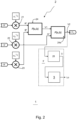
- FIG. 1 schematically shows a video communication system comprising a video encoder 221, a transmission channel 204, 205, 206, and a video decoder 220.
- the video encoder 221 is provided for encoding input video data MAST_HDR from a video source ImSRC into a compressed video signal Im_COD.
- the video source may be anything ranging from a hard disk to a cable output from e.g. a television studio, etc.
- the video encoder in this example comprising a color transformer 202 and a video compressor 203, in addition to grading a master HDR image, performs a set of often reversible color transformation functions F_ct is defined. Without intending to lose generalization, we assume this to comprise at least one luminance mapping function FL (however, there may be further functions and data, e.g. specifying how the saturation of pixels should change from the HDR to the SDR grading).
- This luminance mapping function defines the mapping between different gradings, in this example the mapping from HDR to SDR reference grading (the latter in Fig. 2 being the LDR image Im_LDR to be communicated to receivers.
- the master HDR image is input to color transformer 202 which is configured to apply the F_L luminance mapping to the luminances of the master HDR image (MAST_HDR), to obtain all corresponding luminances written into output image Im_SDR.
- F_ct i.e. at least F_L
- the applied functions F_ct are written in (dynamic, handling) metadata to be co-communicated with the encoded images Im_COD.
- the video compressor 203 is an MPEG HEVC encoder, but various alternative compression technologies would be suitable, like VVC, or AV1, and the like.
- the video compressor 203 forms part of video encoder 221 (which in turn may be comprised in various forms of video creation apparatuses or systems).
- the compressed image Im_COD is transmitted to at least one receiver over some image communication medium 205 (e.g. a satellite or cable or internet transmission, e.g. according to ATSC 3.0, or DVB, etc.
- the HDR video signal may also be communicated e.g. over a cable between two video handling apparatuses).
- transmission formatter 204 may apply depending on the system such techniques as e.g. packetization, modulation, transmission protocol control, etc. This will typically apply integrated circuits.
- a corresponding video signal unformatter 206 applies the necessary unformatting methods to re-obtain the compressed video as a set of e.g. compressed HEVC images (i.e. HEVC image data), e.g. demodulation etc.
- compressed HEVC images i.e. HEVC image data
- Video decompressor 207 does the e.g. HEVC decompression, to obtain a stream of pixelated uncompressed images Im_RLDR, which in the present example are SDR images, but in the other mode would be HDR images.
- the video decompressor will also unpack the necessary luminance mapping function F_L from the e.g. SEI messages, or in general color transformation functions F_ct.
- the images and functions are input to a (decoder) color transformer 208 which is arranged to transform the LDR image to an image having different dynamic range.
- the color transformer 208 is configured to transform the LDR image to an image having a higher dynamic range (i.e. of PL_V higher than 100 nit, and typically at least a few times higher, e.g. 5x). This results in a reconstructed HDR image Im_RHDR.
- a higher dynamic range i.e. of PL_V higher than 100 nit, and typically at least a few times higher, e.g. 5x.
- a 3000 nit reconstructed HDR image Im_RHDR may be reconstructed as close approximation of the master HDR image (MAST_HDR) by applying the inverse color transformations IF_ct of the color transformations F_ct used at the encoding side to make the Im_LDR from the MAST_HDR.
- This image can then be sent e.g. to a display 210 for further display adaptation, but the making of a display adapted image can also happen in one go, during the decoding, by using in the color transformer an FL_DA function (determined in an offline loop, e.g. in firmware) instead of the F_L function.
- the color transformer may also comprise a display adaptation unit 209, to derive the FL_DA function.
- the optimized e.g. 3000 nit display adapted image Im3000nit may be sent e.g. to a display 210 if the video decoder 220 is comprised e.g. in a settopbox or computer etc., or it may be sent to a display panel in case the decoder resides in e.g. a mobile phone, or it may be communicated to a movie theatre projector if the decoder resides in e.g. some internet-connected server, etc.
- FIG. 2 schematically shows an embodiment of an improved image processing apparatus 1 according to the present invention that is provided to compute an output luminance of an output image with an output dynamic range from an input color specified by non-linear color components in an input dynamic range with a modest computational effort.
- the computed output luminance is a reasonably accurate approximation of the actual luminance corresponding to the input color taking into account the transformation from the input dynamic range to the output dynamic range.
- the improved image processing apparatus shown in FIG. 2 comprises a luminance calculation circuit 2 to calculate an input luminance Li from non-linear color components R', G', B' in the image data Im_RLDR that specify an input color and a luminance mapper 3 to apply a luminance mapping function to the input luminance Li to obtain an output luminance Lo.
- the luminance calculation circuit 2 is configured to compute an output value as a function P(a,b) of a first input value (a) and a second input value (b) at respective inputs.
- the function P(a,b) selects one of the first input value and the second input value that is greater than or equal to the other one of said first input value and said second input value as a primary value and it selects the other one of the first input value and the second input value as a secondary value.
- the first and the second input value are equal it is not relevant, which one is selected as the primary value, and which as the secondary value. In order to avoid a deadlock situation the selection can be performed as follows.
- the selection can be performed as select always the second input value (b) as the primary value, unless the second input value is less than the first input value. In the latter case the first input value is selected as the primary value.
- a still further alternative approach is to randomly select one of the first and the second input value as the primary value in case they are equal. In any case, the one of the input values that is not selected as the primary value is selected as the secondary value.
- the function P computes the output value as a linear weighting of the primary value and the secondary value if the primary value is less than a product of the secondary value with a constant, and determines the primary value as the output value otherwise.
- the luminance calculation circuit 2 applies the function P first to compute a first intermediary output value V1 with a first one R" and a second one B" of a set of intermediate color components R", G",B" at its respective inputs. Subsequently, it applies the function P to compute a second intermediate value V2 from the first intermediate output value V1 and a third one G" of the set of intermediary color components at its respective inputs.
- Which of the red, green and blue components acts as first, second or third input in our approximation doesn't matter a lot. But there is a slight preference to first combine red and blue, which have the smaller coefficients in the luma mix equation.
- the luminance calculation circuit 2 has a first and a second computation block 24, 24a to compute the first intermediary output value V1 and the second intermediary output value V2.
- the luminance calculation circuit 2 may comprise a (optional) luma to luminance mapping circuit 25 with which is configured to obtain the input luminance Li as a power ⁇ of the second intermediate value V2.
- V2 is a constant luminance luma output.
- luma does not represent luminance accurately for all colors, except on the achromatic axis of greys. Due to the non-linearity there is some reduction of the luma as calculated by applying the three weight coefficients to the non-linear (i.e. gamma or power function power(x;gamma)) coefficients, or first linearizing the three color components, then calculating the luminance in the linear domain, and then calculating the luma again on a single dimension being the luminance.
- the latter one is a luma coding which is an exact representation of the luminance of any color, irrespective of whether that color is saturated blue etc., and that version of the luma is called "constant luminance luma", and what we have as output V2.
- the luminance mapper 3 applies a luminance mapping function to an input luminance Li to obtain an output luminance Lo. So for this a circuit will be incorporated which converts the constant luminance luma to the input luminance for the luminance mapper, which is luma to luminance mapping circuit 25.
- the luma to luminance mapping circuit 25 is an optional component of the luminance calculation circuit 2.
- Some embodiments may want to do the luminance processing actually in the corresponding luma domain, in which case luminance mapper 3 will work in the luma domain, on inputs being the intermediate value V2, and circuit 25 will not be present.
- the luminance processing in e.g. a dynamic range change in e.g. a television which changes its input images to a different dynamic range, or a video coder which codes master videos as to be communicated videos of a different dynamic range, will use what we have drawn as luminance mapper circuit 3' (with or without circuit 25).
- Procesing in the luma domain needs less bits for the data words representing the pixel luminances (e.g. 14 bits instead of 28).
- the power with which the second intermediate value is raised to obtain the input luminance is a square power and the respective weights are the square roots of the respective constants of the luminance equation for the primary video coding system. This is of particular application for the Rec. 709 video coding convention.
- the intermediate color components R", G",B" are respective weighted values of the non-linear input color components R', G', B'. That is, the non-linear input color components R', G', B' are multiplied 21, 22, 23 by respective weights that are characteristic for a primary video coding system 221 from which the non-linear input color components R', G', B' are received.
- the various elements 21, 22, 23, 24, 24a, 25 and 3 are shown as separate computation blocks. Such an embodiment is also favorable to optimize computation speed. This is rendered possible, in that the computations can be performed in a pipelined process, wherein the luminance mapper 3 applies its luminance mapping function to the input luminance Li to obtain an output luminance Lo of a pixel k, wherein the luma to luminance mapping circuit 25 yields the input luminance Li as a power ⁇ of the second intermediate value V2 for a subsequent pixel k+1, wherein the second computation block 24a computes the second intermediary output value V2 for a further subsequent pixel k+2, wherein the first computation block 24 computes the first intermediary output value V1 for a further subsequent pixel k+3, and wherein the elements 21, 22, 23 perform the multiplications to weight the non-linear input color components R', G', B'.
- these computation blocks can be implemented as dedicated hardware.
- one or more or all computation blocks can be implemented as by software executed on a programmable processor, e.g. a CPU or a GPU.
- the first computation block 24 computes the first intermediary output value V1 from the intermediate color components R" and B" and subsequently, the second computation block 24a computes the second intermediate value V2 from the first intermediate output value V1 and intermediary color component G" at its respective inputs.
- the inputs for the first computation block 24 are the intermediary color components R" and G" and the second computation block 24a receives the intermediary color component B" as an input.
- the inputs for the first computation block 24 are the intermediary color components B" and G" and the second computation block 24a receives the intermediary color component R" as an input.
- the implementation shown in FIG 2 is relatively accurate as compared to these alternatives. This is because typically, the green color component provides a dominating contribution to the luminance. By selecting the green color component as the third intermediate color component, an approximation error is introduced in only one stage of the luminance calculation circuit.
- FIG. 3 shows an exemplary embodiment of a computation block to perform the function P.
- computation elements 241, 242 respectively output the primary value Vp and the secondary value Vs.
- the multiplication elements 243, 244 respectively multiply the primary value Vp with a primary weight ⁇ and the secondary value Vs with a secondary weight ⁇ .
- a summation element 246 computes the sum of the weighted primary value and the weighted secondary value. This weighted sum is provided at a first input of a multiplexer 248.
- the primary value Vp is provided at a second input of the multiplexer 248.
- the multiplexer 248 is controlled by the output of a comparator 247. The latter compares the primary value Vp with the product of the secondary value Vs and a constant. The constant is equal to the value of the secondary weight ⁇ divided by one minus the primary weight ⁇ . If the primary value Vp exceeds the value of the product, the multiplexer selects the primary value Vp as and otherwise it selects the weighted
- the non-linear color components R', G', B' are the square root of the input color components R,G, B.
- Eq. 5b gives the best approximation, because of the dominant effect of the color green on the luminance.
- the multiplication element 244' performs a binary shift right by 1 operation, therewith providing the value Vs/2.
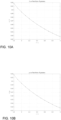
- FIG. 5A compares the value Y ⁇ that is estimated with the circuit 2 using an implementation of the function P with the values 7/8 and 1/2 as the primary weight and the secondary weight respectively, with the mathematically correct value Y for 10 7 random samples possible values of R", G" and B".
- FIG. 5B shows the relative deviation between the estimated value and the mathematically correct value.
- the estimated value reasonably well approximates the mathematically correct value, although a small bias can be seen particularly for intermediate values of Y .
- FIG. 6A compares the value Y ⁇ that is estimated with the circuit 2 using another implementation of the function P.
- the primary weight ⁇ and the secondary weight ⁇ are chosen as follows:
- the estimation in this case is bias free and with a maximum relative error of about 4%.
- the mathematically correct luma Y 1 ⁇ can be estimated bias free with an accuracy of about ⁇ 4%.
- FIG. 10A, 10B Suitable values of the primary weights and the secondary weights that are not explicitly displayed in the table above can be found by interpolation, as illustrated in FIG. 10A, 10B .
- FIG. 10A and 10B respectively show the value for the primary weight ⁇ and the value for the secondary weight ⁇ to be selected as a function of gamma.
- the algorithmic components disclosed in this text may (entirely or in part) be realized in practice as hardware (e.g. parts of an application specific IC) or as software running on a special digital signal processor, or a generic processor, etc. They may be semi-automatic in a sense that at least some user input may be/have been (e.g. in factory, or consumer input, or other human input) present.
- all variants of a creation side like an encoder may be similar as or correspond to corresponding apparatuses at a consumption side of a decomposed system, e.g. a decoder and vice versa.
- Several components of the embodiments may be encoded as specific signal data in a signal for transmission, or further use such as coordination, in any transmission technology between encoder and decoder, etc.
- the word "apparatus” in this application is used in its broadest sense, namely a group of means allowing the realization of a particular objective, and can hence e.g. be (a small part of) an IC, or a dedicated appliance (such as an appliance with a display), or part of a networked system, etc.
- "Arrangement” or “system” is also intended to be used in the broadest sense, so it may comprise inter alia a single physical, purchasable apparatus, a part of an apparatus, a collection of (parts of) cooperating apparatuses, etc.
- the computer program product denotation should be understood to encompass any physical realization of a collection of commands enabling a generic or special purpose processor, after a series of loading steps (which may include intermediate conversion steps, such as translation to an intermediate language, and a final processor language) to enter the commands into the processor, to execute any of the characteristic functions of an invention.
- the computer program product may be realized as data on a carrier such as e.g. a disk or tape, data present in a memory, data traveling via a network connection -wired or wireless-, or program code on paper.
- characteristic data required for the program may also be embodied as a computer program product. Such data may be (partially) supplied in any way.
- the invention or any data usable according to any approach of the present embodiments like video data may also be embodied as signals on data carriers, which may be removable memories like optical disks, flash memories, removable hard disks, portable devices writeable via wireless means, etc.
Landscapes
- Engineering & Computer Science (AREA)
- Multimedia (AREA)
- Signal Processing (AREA)
- Processing Of Color Television Signals (AREA)
Priority Applications (6)
| Application Number | Priority Date | Filing Date | Title |
|---|---|---|---|
| EP22213709.3A EP4387221A1 (de) | 2022-12-15 | 2022-12-15 | Bildverarbeitungsvorrichtung und bildverarbeitungsverfahren |
| EP23814504.9A EP4635169A1 (de) | 2022-12-15 | 2023-12-05 | Bildverarbeitungsvorrichtung und bildverarbeitungsverfahren |
| CN202380086016.6A CN120380745A (zh) | 2022-12-15 | 2023-12-05 | 图像处理装置及图像处理方法 |
| JP2025534246A JP2025541221A (ja) | 2022-12-15 | 2023-12-05 | 画像処理装置及び画像処理方法 |
| PCT/EP2023/084190 WO2024126144A1 (en) | 2022-12-15 | 2023-12-05 | Image processing apparatus and image processing method |
| GB2319107.5A GB2627343B (en) | 2022-12-15 | 2023-12-14 | Image processing apparatus and image processing method |
Applications Claiming Priority (1)
| Application Number | Priority Date | Filing Date | Title |
|---|---|---|---|
| EP22213709.3A EP4387221A1 (de) | 2022-12-15 | 2022-12-15 | Bildverarbeitungsvorrichtung und bildverarbeitungsverfahren |
Publications (1)
| Publication Number | Publication Date |
|---|---|
| EP4387221A1 true EP4387221A1 (de) | 2024-06-19 |
Family
ID=84537223
Family Applications (1)
| Application Number | Title | Priority Date | Filing Date |
|---|---|---|---|
| EP22213709.3A Withdrawn EP4387221A1 (de) | 2022-12-15 | 2022-12-15 | Bildverarbeitungsvorrichtung und bildverarbeitungsverfahren |
Country Status (2)
| Country | Link |
|---|---|
| EP (1) | EP4387221A1 (de) |
| WO (1) | WO2024126144A1 (de) |
Citations (2)
| Publication number | Priority date | Publication date | Assignee | Title |
|---|---|---|---|---|
| US20190082186A1 (en) * | 2016-01-28 | 2019-03-14 | Koninklijke Philips N.V. | Encoding and decoding hdr videos |
| US20210272497A1 (en) * | 2017-05-05 | 2021-09-02 | Koninklijke Philips N.V. | Optimized decoded high dynamic range image saturation |
-
2022
- 2022-12-15 EP EP22213709.3A patent/EP4387221A1/de not_active Withdrawn
-
2023
- 2023-12-05 WO PCT/EP2023/084190 patent/WO2024126144A1/en not_active Ceased
Patent Citations (2)
| Publication number | Priority date | Publication date | Assignee | Title |
|---|---|---|---|---|
| US20190082186A1 (en) * | 2016-01-28 | 2019-03-14 | Koninklijke Philips N.V. | Encoding and decoding hdr videos |
| US20210272497A1 (en) * | 2017-05-05 | 2021-09-02 | Koninklijke Philips N.V. | Optimized decoded high dynamic range image saturation |
Also Published As
| Publication number | Publication date |
|---|---|
| WO2024126144A1 (en) | 2024-06-20 |
Similar Documents
| Publication | Publication Date | Title |
|---|---|---|
| JP6396596B2 (ja) | 色彩恒常性を有するルミナンス変更画像処理 | |
| US11430095B2 (en) | Automatic display management metadata generation for gaming and/or SDR+ contents | |
| US10937135B2 (en) | Saturation processing specification for dynamic range mappings | |
| KR102061349B1 (ko) | 높은 다이내믹 레인지 이미지 신호의 생성 및 처리 | |
| JP5690267B2 (ja) | コンテンツ配信のための方法およびシステム | |
| CN102388612B (zh) | 高动态范围、可视动态范围和宽色域视频的分层压缩 | |
| US11272195B2 (en) | Multi-range HDR video coding | |
| JP2018534883A (ja) | 映像復号化器における高ダイナミックレンジ適応演算 | |
| US12548130B2 (en) | Image enhancement via global and local reshaping | |
| CN116167950A (zh) | 图像处理方法、装置、电子设备及存储介质 | |
| JP7300070B2 (ja) | 飽和色のための改善されたhdrカラー処理 | |
| EP4387221A1 (de) | Bildverarbeitungsvorrichtung und bildverarbeitungsverfahren | |
| EP4635169A1 (de) | Bildverarbeitungsvorrichtung und bildverarbeitungsverfahren | |
| Gadgil et al. | The technology behind the exceptional visual experience via high dynamic range | |
| EP4383186A1 (de) | Einstellung von der bildhelligkeit für wahrnehmbar einheitlichen elektrooptischen übertragungsfunktion |
Legal Events
| Date | Code | Title | Description |
|---|---|---|---|
| PUAI | Public reference made under article 153(3) epc to a published international application that has entered the european phase |
Free format text: ORIGINAL CODE: 0009012 |
|
| STAA | Information on the status of an ep patent application or granted ep patent |
Free format text: STATUS: THE APPLICATION HAS BEEN PUBLISHED |
|
| AK | Designated contracting states |
Kind code of ref document: A1 Designated state(s): AL AT BE BG CH CY CZ DE DK EE ES FI FR GB GR HR HU IE IS IT LI LT LU LV MC ME MK MT NL NO PL PT RO RS SE SI SK SM TR |
|
| STAA | Information on the status of an ep patent application or granted ep patent |
Free format text: STATUS: THE APPLICATION IS DEEMED TO BE WITHDRAWN |
|
| 18D | Application deemed to be withdrawn |
Effective date: 20241220 |