EP4387150A1 - Datenübertragungsverfahren und -vorrichtung - Google Patents
Datenübertragungsverfahren und -vorrichtung Download PDFInfo
- Publication number
- EP4387150A1 EP4387150A1 EP22882727.5A EP22882727A EP4387150A1 EP 4387150 A1 EP4387150 A1 EP 4387150A1 EP 22882727 A EP22882727 A EP 22882727A EP 4387150 A1 EP4387150 A1 EP 4387150A1
- Authority
- EP
- European Patent Office
- Prior art keywords
- reference signal
- modulation
- signal
- data
- coding parameter
- Prior art date
- Legal status (The legal status is an assumption and is not a legal conclusion. Google has not performed a legal analysis and makes no representation as to the accuracy of the status listed.)
- Pending
Links
- 238000000034 method Methods 0.000 title claims abstract description 113
- 230000005540 biological transmission Effects 0.000 title claims abstract description 39
- 230000003595 spectral effect Effects 0.000 claims abstract description 37
- 238000004891 communication Methods 0.000 claims description 100
- 238000004590 computer program Methods 0.000 claims description 39
- 238000012545 processing Methods 0.000 claims description 35
- 230000015654 memory Effects 0.000 claims description 20
- 230000006870 function Effects 0.000 description 45
- 230000000875 corresponding effect Effects 0.000 description 33
- 238000010586 diagram Methods 0.000 description 23
- 230000011664 signaling Effects 0.000 description 18
- 238000005516 engineering process Methods 0.000 description 14
- 230000008569 process Effects 0.000 description 13
- 101100401578 Saccharomyces cerevisiae (strain ATCC 204508 / S288c) MIC12 gene Proteins 0.000 description 11
- 238000001914 filtration Methods 0.000 description 9
- 238000013461 design Methods 0.000 description 8
- 239000004065 semiconductor Substances 0.000 description 7
- 229910044991 metal oxide Inorganic materials 0.000 description 6
- 150000004706 metal oxides Chemical class 0.000 description 6
- 238000013507 mapping Methods 0.000 description 5
- 125000004122 cyclic group Chemical group 0.000 description 4
- 230000007774 longterm Effects 0.000 description 4
- 230000010363 phase shift Effects 0.000 description 4
- 230000001174 ascending effect Effects 0.000 description 3
- 239000000969 carrier Substances 0.000 description 3
- 230000001413 cellular effect Effects 0.000 description 3
- 229910000577 Silicon-germanium Inorganic materials 0.000 description 2
- 230000008859 change Effects 0.000 description 2
- 230000000295 complement effect Effects 0.000 description 2
- 238000005070 sampling Methods 0.000 description 2
- JBRZTFJDHDCESZ-UHFFFAOYSA-N AsGa Chemical compound [As]#[Ga] JBRZTFJDHDCESZ-UHFFFAOYSA-N 0.000 description 1
- 108010076504 Protein Sorting Signals Proteins 0.000 description 1
- LEVVHYCKPQWKOP-UHFFFAOYSA-N [Si].[Ge] Chemical compound [Si].[Ge] LEVVHYCKPQWKOP-UHFFFAOYSA-N 0.000 description 1
- 230000009471 action Effects 0.000 description 1
- 238000003491 array Methods 0.000 description 1
- 238000013473 artificial intelligence Methods 0.000 description 1
- 230000009286 beneficial effect Effects 0.000 description 1
- 239000013256 coordination polymer Substances 0.000 description 1
- 238000013500 data storage Methods 0.000 description 1
- 230000004069 differentiation Effects 0.000 description 1
- 230000006855 networking Effects 0.000 description 1
- 230000003287 optical effect Effects 0.000 description 1
- 239000013307 optical fiber Substances 0.000 description 1
- 239000002245 particle Substances 0.000 description 1
- 230000008054 signal transmission Effects 0.000 description 1
- 238000012546 transfer Methods 0.000 description 1
Images


Classifications
-
- H—ELECTRICITY
- H04—ELECTRIC COMMUNICATION TECHNIQUE
- H04L—TRANSMISSION OF DIGITAL INFORMATION, e.g. TELEGRAPHIC COMMUNICATION
- H04L1/00—Arrangements for detecting or preventing errors in the information received
- H04L1/0001—Systems modifying transmission characteristics according to link quality, e.g. power backoff
- H04L1/0002—Systems modifying transmission characteristics according to link quality, e.g. power backoff by adapting the transmission rate
- H04L1/0003—Systems modifying transmission characteristics according to link quality, e.g. power backoff by adapting the transmission rate by switching between different modulation schemes
- H04L1/0004—Systems modifying transmission characteristics according to link quality, e.g. power backoff by adapting the transmission rate by switching between different modulation schemes applied to control information
-
- H—ELECTRICITY
- H04—ELECTRIC COMMUNICATION TECHNIQUE
- H04L—TRANSMISSION OF DIGITAL INFORMATION, e.g. TELEGRAPHIC COMMUNICATION
- H04L1/00—Arrangements for detecting or preventing errors in the information received
- H04L1/0001—Systems modifying transmission characteristics according to link quality, e.g. power backoff
- H04L1/0002—Systems modifying transmission characteristics according to link quality, e.g. power backoff by adapting the transmission rate
- H04L1/0003—Systems modifying transmission characteristics according to link quality, e.g. power backoff by adapting the transmission rate by switching between different modulation schemes
- H04L1/0005—Systems modifying transmission characteristics according to link quality, e.g. power backoff by adapting the transmission rate by switching between different modulation schemes applied to payload information
-
- H—ELECTRICITY
- H04—ELECTRIC COMMUNICATION TECHNIQUE
- H04L—TRANSMISSION OF DIGITAL INFORMATION, e.g. TELEGRAPHIC COMMUNICATION
- H04L1/00—Arrangements for detecting or preventing errors in the information received
- H04L1/0001—Systems modifying transmission characteristics according to link quality, e.g. power backoff
- H04L1/0009—Systems modifying transmission characteristics according to link quality, e.g. power backoff by adapting the channel coding
- H04L1/001—Systems modifying transmission characteristics according to link quality, e.g. power backoff by adapting the channel coding applied to control information
-
- H—ELECTRICITY
- H04—ELECTRIC COMMUNICATION TECHNIQUE
- H04L—TRANSMISSION OF DIGITAL INFORMATION, e.g. TELEGRAPHIC COMMUNICATION
- H04L1/00—Arrangements for detecting or preventing errors in the information received
- H04L1/0001—Systems modifying transmission characteristics according to link quality, e.g. power backoff
- H04L1/0009—Systems modifying transmission characteristics according to link quality, e.g. power backoff by adapting the channel coding
- H04L1/0011—Systems modifying transmission characteristics according to link quality, e.g. power backoff by adapting the channel coding applied to payload information
-
- H—ELECTRICITY
- H04—ELECTRIC COMMUNICATION TECHNIQUE
- H04L—TRANSMISSION OF DIGITAL INFORMATION, e.g. TELEGRAPHIC COMMUNICATION
- H04L1/00—Arrangements for detecting or preventing errors in the information received
- H04L1/0001—Systems modifying transmission characteristics according to link quality, e.g. power backoff
- H04L1/0023—Systems modifying transmission characteristics according to link quality, e.g. power backoff characterised by the signalling
-
- H—ELECTRICITY
- H04—ELECTRIC COMMUNICATION TECHNIQUE
- H04L—TRANSMISSION OF DIGITAL INFORMATION, e.g. TELEGRAPHIC COMMUNICATION
- H04L27/00—Modulated-carrier systems
- H04L27/26—Systems using multi-frequency codes
- H04L27/2601—Multicarrier modulation systems
- H04L27/2602—Signal structure
- H04L27/261—Details of reference signals
- H04L27/2613—Structure of the reference signals
-
- H—ELECTRICITY
- H04—ELECTRIC COMMUNICATION TECHNIQUE
- H04L—TRANSMISSION OF DIGITAL INFORMATION, e.g. TELEGRAPHIC COMMUNICATION
- H04L5/00—Arrangements affording multiple use of the transmission path
- H04L5/003—Arrangements for allocating sub-channels of the transmission path
- H04L5/0044—Allocation of payload; Allocation of data channels, e.g. PDSCH or PUSCH
-
- H—ELECTRICITY
- H04—ELECTRIC COMMUNICATION TECHNIQUE
- H04L—TRANSMISSION OF DIGITAL INFORMATION, e.g. TELEGRAPHIC COMMUNICATION
- H04L5/00—Arrangements affording multiple use of the transmission path
- H04L5/003—Arrangements for allocating sub-channels of the transmission path
- H04L5/0048—Allocation of pilot signals, i.e. of signals known to the receiver
- H04L5/0051—Allocation of pilot signals, i.e. of signals known to the receiver of dedicated pilots, i.e. pilots destined for a single user or terminal
-
- H—ELECTRICITY
- H04—ELECTRIC COMMUNICATION TECHNIQUE
- H04L—TRANSMISSION OF DIGITAL INFORMATION, e.g. TELEGRAPHIC COMMUNICATION
- H04L5/00—Arrangements affording multiple use of the transmission path
- H04L5/0091—Signalling for the administration of the divided path, e.g. signalling of configuration information
- H04L5/0094—Indication of how sub-channels of the path are allocated
Definitions
- the application relates to the field of communication technologies, and in particular, to a data transmission method and an apparatus thereof.
- phase noise phase noise
- PTRS phase tracking reference signal
- a network device may configure frequency domain density and time domain density for a PTRS in an orthogonal frequency division multiplexing (orthogonal frequency division multiplexing, OFDM) technology.
- the time domain density may be a value in 4, 2, or 1, where 1, 2, and 4 respectively indicate that there is one PTRS on every one time domain symbol, every two time domain symbols, and every four time domain symbols.
- the network device does not configure the time domain density and the frequency domain density for the PTRS, there is a PTRS on each scheduled time domain symbol, and there is one PTRS in every two RBs in the scheduled bandwidth.
- Embodiments of the application provide a data transmission method and an apparatus thereof, to transmit data based on a reference signal, thereby helping improve data transmission efficiency.
- an embodiment of the application provides a data transmission method.
- the method may be performed by a transmit end, or may be performed by a chip used in the transmit end.
- the method includes: The transmit end determines a reference signal and a data signal, and sends the reference signal and the data signal.
- the reference signal is for transmitting first data.
- the data signal is for transmitting second data.
- a resource element carrying the reference signal and a resource element carrying the data signal belong to a same frequency domain resource assignment.
- a modulation and coding parameter of the reference signal is smaller than a modulation and coding parameter of the data signal.
- the modulation and coding parameter includes one or more of the following: a modulation and coding scheme MCS index, a modulation order, a code rate, or spectral efficiency.
- the first data is transmitted based on the reference signal, thereby helping improve data transmission efficiency.
- the modulation and coding parameter of the reference signal is smaller than the modulation and coding parameter of the data signal, so that a lower signal-to-noise ratio is needed for demodulating the reference signal, a success rate of demodulating the reference signal at a receive end is higher, and data can be successfully transmitted based on the reference signal, thereby helping improve the data transmission efficiency.
- the modulation and coding parameter of the reference signal is determined based on the modulation and coding parameter of the data signal, or the modulation and coding parameter of the data signal is determined based on the modulation and coding parameter of the reference signal.
- the modulation and coding parameter of the reference signal is determined based on one or more of the following parameters: the modulation and coding parameter of the data signal, a quantity of resource elements occupied by the second data, power of the second data, frequency domain density of the reference signal, time domain density of the reference signal, power of the reference signal, a quantity of reference signals, a quantity of reference signals included in a reference signal block to which the reference signal belongs, or a data volume of the first data.
- the method further includes: The transmit end sends indication information, where the indication information indicates the modulation and coding parameter of the reference signal.
- a resource block carrying the reference signal further carries first information.
- the reference signal is transmitted based on a first transport block, and the first information is transmitted based on a second transport block.
- the reference signal may exist as an independent transport block, and other information (that is, the first information) carried in the resource block carrying the reference signal and the reference signal are transmitted based on different transport blocks, thereby helping avoid interference of the first information to the reference signal.
- the first transport block and the second transport block are a same transport block.
- the other information (that is, the first information) carried in the resource block carrying the reference signal and the reference signal are transmitted based on a same transport block, thereby helping reduce used transport block resources.
- the reference signal includes a first reference signal and a second reference signal.
- a resource element carrying the first reference signal is adjacent to a resource element carrying the second reference signal in at least one of the following domains: time domain or frequency domain.
- the first reference signal is a reference signal having a largest modulation and coding parameter in the reference signal for transmitting the first data.
- the second reference signal is a reference signal having a smallest modulation and coding parameter in the reference signal for transmitting the first data.
- a smaller modulation and coding parameter of the signal indicates a lower signal-to-noise ratio needed for demodulating the signal at the receive end.
- the second reference signal is the reference signal having the smallest modulation and coding parameter in the reference signal for transmitting the first data. Therefore, a lower signal-to-noise ratio is needed for demodulating the second reference signal, and a success rate of demodulating the second reference signal at the receive end is higher, so that an estimation result on phase noise of the second reference signal can be successfully obtained.
- the resource element carrying the first reference signal is adjacent to the resource element carrying the second reference signal in at least one of the following domains: time domain or frequency domain. Therefore, the estimation result on the phase noise of the second reference signal may be used to determine an estimation result on phase noise of the first reference signal. This manner helps improve accuracy of the estimation result of the phase noise of the second reference signal, and helps improve phase noise estimation performance.
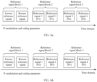
- the first data is specifically transmitted based on a plurality of reference signal blocks.
- Each reference signal block includes a plurality of reference signals, and each reference signal block includes at least two reference signals that have different modulation and coding parameters.
- the technical solution helps improve efficiency of transmitting data based on the reference signal.
- the reference signal is a phase tracking reference signal.
- the first data is specifically transmitted based on a first reference signal block and a second reference signal block.
- a modulation and coding parameter of the reference signal is the same as a modulation and coding parameter of a corresponding reference signal in the second reference signal block.
- a modulation and coding parameter of a reference signal in one reference signal block (for example, the first reference signal block) needs to be indicated, and there is no need to indicate a modulation and coding parameter of a reference signal in another reference signal block (for example, the second reference signal block), thereby helping reduce the used resources.
- the first data is specifically transmitted based on a third reference signal block and a fourth reference signal block.
- a modulation and coding parameter of each reference signal in the third reference signal block is a first modulation and coding parameter.
- a modulation and coding parameter of each reference signal in the fourth reference signal block is a second modulation and coding parameter.
- the third reference signal block and the fourth reference signal block each include only reference signals having a same modulation and coding parameter, and reference signals in different reference signal blocks (that is, the third reference signal block and the fourth reference signal block) have different modulation and coding parameters.
- the third reference signal block and the fourth reference signal block have different modulation and coding parameters.
- orthogonal cover code OCC information of the reference signal is the same as OCC information of a demodulated reference signal.
- the OCC information of the reference signal may not need to be separately indicated, thereby helping reduce the used resources.
- an embodiment of the application provides another data transmission method.
- the method may be performed by a receive end, or may be performed by a chip used in the receive end.
- the method includes: The receive end obtains a first signal and a second signal, demodulates the first signal to obtain first data, and demodulates the second signal to obtain second data.
- the first signal includes a signal obtained after a reference signal is transmitted.
- the second signal includes a signal obtained after a data signal is transmitted.
- a resource element carrying the reference signal and a resource element carrying the data signal belong to a same frequency domain resource assignment.
- a modulation and coding parameter of the reference signal is smaller than a modulation and coding parameter of the data signal.
- the modulation and coding parameter includes one or more of the following: a modulation and coding scheme MCS index, a modulation order, a code rate, or spectral efficiency.
- the first data is transmitted based on the reference signal, thereby helping improve data transmission efficiency.
- the modulation and coding parameter of the reference signal is smaller than the modulation and coding parameter of the data signal, so that a lower signal-to-noise ratio is needed for demodulating the reference signal, a success rate of demodulating the reference signal at the receive end is higher, and data can be successfully transmitted based on the reference signal, thereby helping improve the data transmission efficiency.
- the modulation and coding parameter of the reference signal is determined based on the modulation and coding parameter of the data signal, or the modulation and coding parameter of the data signal is determined based on the modulation and coding parameter of the reference signal.
- the modulation and coding parameter of the reference signal is determined based on one or more of the following parameters: the modulation and coding parameter of the data signal, a quantity of resource elements occupied by the second data, power of the second data, frequency domain density of the reference signal, time domain density of the reference signal, power of the reference signal, a quantity of reference signals, a quantity of reference signals included in a reference signal block to which the reference signal belongs, or a data volume of the first data.
- the method further includes: The receive end obtains indication information, where the indication information indicates the modulation and coding parameter of the reference signal.
- a resource block carrying the reference signal further carries first information.
- the reference signal is transmitted based on a first transport block, and the first information is transmitted based on a second transport block.
- the reference signal may exist as an independent transport block, and other information (that is, the first information) carried in the resource block carrying the reference signal and the reference signal are transmitted based on different transport blocks, thereby helping avoid interference of the first information to the reference signal.
- the first transport block and the second transport block are a same transport block.
- the other information (that is, the first information) carried in the resource block carrying the reference signal and the reference signal are transmitted based on a same transport block, thereby helping reduce used transport block resources.
- the reference signal includes a first reference signal and a second reference signal.
- a resource element carrying the first reference signal is adjacent to a resource element carrying the second reference signal in at least one of the following domains: time domain or frequency domain.
- the first reference signal is a reference signal having a largest modulation and coding parameter in the reference signal for transmitting the first data.
- the second reference signal is a reference signal having a smallest modulation and coding parameter in the reference signal for transmitting the first data.
- a smaller modulation and coding parameter of the signal indicates a lower signal-to-noise ratio needed for demodulating the signal at the receive end.
- the second reference signal is the reference signal having the smallest modulation and coding parameter in the reference signal for transmitting the first data. Therefore, a lower signal-to-noise ratio is needed for demodulating the second reference signal, and a success rate of demodulating the second reference signal at the receive end is higher, so that an estimation result on phase noise of the second reference signal can be successfully obtained.
- the resource element carrying the first reference signal is adjacent to the resource element carrying the second reference signal in at least one of the following domains: time domain or frequency domain. Therefore, the estimation result on the phase noise of the second reference signal may be used to determine an estimation result on phase noise of the first reference signal. This manner helps improve the accuracy of the estimation result of the phase noise of the second reference signal, and helps improve the phase noise estimation performance.
- the first signal specifically includes a signal obtained after a reference signal in a plurality of reference signal blocks is transmitted.
- Each reference signal block includes a plurality of reference signals, and each reference signal block includes at least two reference signals that have different modulation and coding parameters.
- the technical solution helps improve efficiency of transmitting data based on the reference signal.
- the reference signal is a phase tracking reference signal.
- the first signal specifically includes a signal obtained after a reference signal in a first reference signal block is transmitted and a signal obtained after a reference signal in a second reference signal block is transmitted.
- a modulation and coding parameter of the reference signal is the same as a modulation and coding parameter of a corresponding reference signal in the second reference signal block.
- the first signal specifically includes a signal obtained after a reference signal in a third reference signal block is transmitted and a signal obtained after a reference signal in a fourth reference signal block is transmitted.
- a modulation and coding parameter of each reference signal in the third reference signal block is a first modulation and coding parameter.
- a modulation and coding parameter of each reference signal in the fourth reference signal block is a second modulation and coding parameter.
- the third reference signal block and the fourth reference signal block each include only reference signals having a same modulation and coding parameter, and reference signals in different reference signal blocks (that is, the third reference signal block and the fourth reference signal block) have different modulation and coding parameters.
- the third reference signal block and the fourth reference signal block have different modulation and coding parameters.
- orthogonal cover code OCC information of the reference signal is the same as OCC information of a demodulated reference signal.
- the OCC information of the reference signal may not need to be separately indicated, thereby helping reduce used resources.
- an embodiment of the application provides a communication apparatus.
- the communication apparatus has some or all of functions of implementing the transmit end in the method examples in the first aspect.
- the functions of the communication apparatus may have functions in some or all of embodiments of the application, or may have a function of independently implementing any embodiment of the application.
- the function may be implemented by hardware, or may be implemented by hardware executing corresponding software.
- the hardware or the software includes one or more units or modules corresponding to the functions.
- a structure of the communication apparatus may include a processing unit and a transceiver unit.
- the processing unit is configured to support the communication apparatus in performing a function of the transmit end in the foregoing method.
- the transceiver unit is configured to support communication between the communication apparatus and another device.
- the communication apparatus may further include a storage unit.
- the storage unit is configured to be coupled to the processing unit and the transceiver unit, and stores a computer program and data that are necessary for the communication apparatus.
- the communication apparatus includes: a processing unit, configured to determine a reference signal and a data signal, where the reference signal is for transmitting first data, the data signal is for transmitting second data, and a resource element carrying the reference signal and a resource element carrying the data signal belong to a same frequency domain resource assignment; and a transceiver unit, configured to send the reference signal and the data signal.
- a modulation and coding parameter of the reference signal is smaller than a modulation and coding parameter of the data signal.
- the modulation and coding parameter includes one or more of the following: a modulation and coding scheme MCS index, a modulation order, a code rate, or spectral efficiency.
- an embodiment of the application provides another communication apparatus.
- the communication apparatus has some or all of functions of implementing the receive end in the method examples in the second aspect.
- the functions of the communication apparatus may have functions in some or all of embodiments of the application, or may have a function of independently implementing any embodiment of the application.
- the function may be implemented by hardware, or may be implemented by hardware executing corresponding software.
- the hardware or the software includes one or more units or modules corresponding to the functions.
- a structure of the communication apparatus may include a processing unit and a transceiver unit.
- the processing unit is configured to support the communication apparatus in performing a function of the receive end in the foregoing method.
- the transceiver unit is configured to support communication between the communication apparatus and another device.
- the communication apparatus may further include a storage unit.
- the storage unit is configured to be coupled to the processing unit and the transceiver unit, and stores a computer program and data that are necessary for the communication apparatus.
- the communication apparatus includes: a transceiver unit, configured to obtain a first signal and a second signal, where the first signal includes a signal obtained after a reference signal is transmitted, the second signal includes a signal obtained after a data signal is transmitted, and a resource element carrying the reference signal and a resource element carrying the data signal belong to a same frequency domain resource assignment; and a processing unit, configured to demodulate the first signal to obtain first data.
- the processing unit is further configured to demodulate the second signal to obtain second data.
- a modulation and coding parameter of the reference signal is smaller than a modulation and coding parameter of the data signal.
- the modulation and coding parameter includes one or more of the following: a modulation and coding scheme MCS index, a modulation order, a code rate, or spectral efficiency.
- the application provides still another communication apparatus, including a processor.
- the processor is coupled to a memory.
- the memory is configured to store program code.
- the processor is configured to invoke the program code from the memory to perform the method according to the first aspect, or perform the method according to the second aspect.
- an embodiment of the present invention provides a computer-readable storage medium.
- the computer-readable storage medium stores a computer program.
- the computer program includes program instructions. When the program instructions are executed by a communication apparatus, the communication apparatus is enabled to perform the method according to the first aspect.
- an embodiment of the present invention provides a computer-readable storage medium.
- the computer-readable storage medium stores a computer program.
- the computer program includes program instructions. When the program instructions are executed by a communication apparatus, the communication apparatus is enabled to perform the method according to the second aspect.
- the application further provides a computer program product including a computer program or instructions.
- the computer program or the instructions is/are run on a computer, the computer is enabled to perform the method according to the first aspect.
- the application further provides a computer program product including a computer program or instructions.
- the computer program or the instructions is/are run on a computer, the computer is enabled to perform the method according to the second aspect.
- the application provides a chip system.
- the chip system includes a logic circuit and an input/output interface, and is configured to implement functions, for example, at least one of determining or processing data and information related in the method, in the first aspect.
- the chip system further includes a memory, and the memory is configured to store a computer program and data that are necessary to a transmit end.
- the chip system may include a chip, or may include a chip and another discrete component.
- the application provides a chip system.
- the chip system includes a logic circuit and an input/output interface, and is configured to implement functions, for example, at least one of determining or processing data and information related in the method, in the second aspect.
- the chip system further includes a memory, and the memory is configured to store a computer program and data that are necessary to a receive end.
- the chip system may include a chip, or may include a chip and another discrete component.
- Resource element Resource element, resource block (resource block, RB), and transport block (transport block, TB)
- the resource element may be a physical resource of a specific granularity.
- the resource element may be a smallest resource unit in the physical resource, and the resource element may also be referred to as a resource element (resource element, RE) or a resource particle.
- the resource element may be a physical resource including a plurality of resource units.
- the resource element may alternatively be another defined physical resource.
- the resource element indicates a period of time in time domain, and indicates a segment of bandwidth in frequency domain. This is not limited in the application.
- the resource element indicates one OFDM symbol in time domain, and indicates one resource block (resource block, RB) in frequency domain.
- One RE indicates one orthogonal frequency division multiplexing (orthogonal frequency division multiplexing, OFDM) symbol in time domain, and indicates one subcarrier in frequency domain.
- the resource block RB includes a plurality of subcarriers or a plurality of REs. For example, one RB includes 12 subcarriers. RBs may be classified into different types, and each type of RB may include different quantities of subcarriers and different subcarrier number ranges.
- the transport block TB indicates a data information block to be encoded.
- the TB may include a plurality of RBs, and the RB may be a minimum unit of a scheduled resource.
- the transport block is a basic unit for data exchange between a media access control (media access control, MAC) sublayer and a physical layer.
- a cyclic check bit may be added after the transport block for check.
- the modulation and coding parameter may include one or more of the following: a modulation and coding scheme (modulation and coding scheme, MCS) index, a modulation order (Modulation Order), a code rate (coding rate, or code rate for short), or spectral efficiency (spectral efficiency, SE).
- MCS modulation and coding scheme
- Modulation Order Modulation Order
- code rate coding rate, or code rate for short
- spectral efficiency SE
- the code rate indicates a ratio of original data bits to encoded data bits.
- the spectral efficiency indicates a quantity of original data bits that can be transmitted on one subcarrier.
- An MCS is a scheme for coding and modulating the original data bits.
- the MCS may include three parameters: the modulation order, the code rate, and the spectral efficiency, and a combination of the three parameters may be indicated by an MCS index (index), as shown in Table 1.
- the MCS index uniquely identifies an MCS.
- MCS table MCS index
- Modulation order Modulation Order
- Q m Target code rate
- R x Spectral efficiency
- Spectral efficiency 0 2 120 0.2344 1 2 157 0.3066 2 2 193 0.3770 3 2 251 0.4902 4 2 308 0.6016 5 2 379 0.7402 6 2 449 0.8770 7 2 526 1.0273 8 2 602 1.1758 9 2 679 1.3262 10 4 340 1.3281 11 4 378 1.4766 12 4 434 1.6953 13 4 490 1.9141 14 4 553 2.1602 15 4 616 2.4063 16 4 658 2.5703 17 6 438 2.5664 18 6 466 2.7305 19 6 517 3.0293 20 6 567 3.3223 21 6 616 3.6094 22 6 666 3.9023 23 6 719 4.2129 24 6 772 4.5234 25 6 822 4.8164 26 6 873 5.1152 27 6 910 5.3320 28 6 948 5.5547
- Q m in the second column is the modulation order.
- 2, 4, and 6 respectively indicate QPSK, 16QAM, and 64QAM.
- the target code rate (Target code Rate) R x in the third column indicates a product of a code rate (for example, indicated by R) and 1024, where R ⁇ 1.
- R for example, indicated by R
- the modulation and coding scheme may also be referred to as a modulation and coding scheme.
- the MCS index may also be referred to as an MCS number, and two concepts of the MCS index and the MCS number may be interchanged.
- Phase noise phase noise
- phase noise refers to a random change of a phase of an output signal of a communication device caused by various noises of a communication device (for example, various radio frequency components) that sends a signal.
- n 0, 1, ..., or N-1, and is a time-domain sampling point.
- the phase noise is a random phase value generated at each sampling point n.
- a basic principle of estimating the phase noise of the reference signal is as follows: A known reference signal (that is, known x ( n )) is inserted at a transmit end, a received reference signal (that is, known y ( n )) is read at a receive end, and a phase noise value (that is, a value ⁇ ) can be calculated based on x ( n ) and y ( n ) .
- the DCI may include but is not limited to one or more of the following field content:
- a carrier indicator (carrier indicator) field indicates a carrier on which a scheduled physical downlink shared channel (physical downlink shared channel, PDSCH) is located.
- PDSCH physical downlink shared channel
- a bandwidth part indicator (bandwidth part indicator) field determines a bandwidth range of a scheduled PDSCH.
- a frequency domain resource assignment indicates a quantity and a start point of consecutive resource blocks of a frequency domain resource occupied by a PDSCH in a specific bandwidth range. This field indicates a scheduled bandwidth of the PDSCH and a start point of the bandwidth.
- a resource element carrying a reference signal and a resource element carrying a data signal belong to a same frequency domain resource assignment.
- a time domain resource assignment indicates a quantity of consecutive symbols and a start symbol of a time domain resource occupied by a PDSCH.
- Modulation and coding scheme (modulation and coding scheme, MCS).
- New data indicator (New data indicator).
- Redundancy version (Redundancy version).
- FIG. 1a is a schematic diagram of an architecture of a communication system according to an embodiment of the application. As shown in FIG. 1a , the communication system includes a transmit end 101 and a receive end 102.
- the transmit end 101 may determine a reference signal and a data signal, and sends the reference signal and the data signal.
- the reference signal is for transmitting first data.
- the data signal is for transmitting second data.
- a resource element carrying the reference signal and a resource element carrying the data signal belong to a same frequency domain resource assignment.
- a modulation and coding parameter of the reference signal is smaller than a modulation and coding parameter of the data signal.
- the modulation and coding parameter includes one or more of the following: an MCS index, a modulation order, a code rate, or spectral efficiency.
- the receive end 102 may be configured to: obtain a first signal and a second signal, demodulate the first signal to obtain the first data, and demodulate the second signal to obtain the second data.
- the first signal includes a signal obtained after the reference signal is transmitted
- the second signal includes a signal obtained after the data signal is transmitted.
- the signal for example, the reference signal or the data signal
- the signal may be transmitted through a wired channel or a wireless channel.
- the receive end receives a transmitted signal (that is, the first signal or the second signal).
- a signal transmission manner is not limited in the application.
- Data information (that is, the first data) is transmitted based on the reference signal, thereby helping improve data transmission efficiency.
- a smaller modulation and coding parameter of the signal indicates a lower signal-to-noise ratio needed for demodulating the signal at the receive end.
- a signal-to-noise ratio required for demodulating a signal may be understood as follows: When a signal-to-noise ratio of the signal is greater than a signal-to-noise ratio threshold, the receive end may successfully demodulate the signal. Alternatively, when a signal-to-noise ratio of the signal is smaller than or equal to the signal-to-noise ratio threshold, the receive end cannot successfully demodulate the signal.
- the signal-to-noise ratio threshold may be understood as a minimum signal-to-noise ratio required for demodulating the signal.
- a modulation and coding parameter of the reference signal is smaller than a modulation and coding parameter of the data signal, so that a lower signal-to-noise ratio is needed for demodulating the reference signal, a success rate of demodulating the reference signal at the receive end is higher, and data can be successfully transmitted based on the reference signal, thereby helping improve the data transmission efficiency.
- the reference signal and the data signal may be transmitted based on a multi-carrier waveform, or the reference signal and the data signal may be transmitted based on a single-carrier waveform.
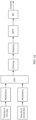
- the transmit end sequentially performs modulation (modulation), mapping (mapping), and inverse fast Fourier transform (inverse fast Fourier transform, IFFT), and then sends a signal (for example, the reference signal and the data signal) based on radio frequency (radio frequency, RF).
- Modulation indicates that a data bit of the data (for example, the first data and the second data) is modulated to a modulation symbol.
- Mapping indicates that a signal is mapped to a sent subcarrier (for example, multiple carriers or a single carrier).
- IFFT indicates that inverse Fourier transform is performed on a frequency-domain signal, to transform the frequency-domain signal into a time-domain signal.
- a cyclic prefix (cyclic prefix, CP) may be further added.
- the receive end after receiving a signal (the first signal and the second signal) via a radio frequency unit, the receive end sequentially performs fast Fourier transform (fast Fourier transform, FFT), demapping, and demodulation, obtains the first data based on the first signal, and obtains the second data based on the second signal.
- FFT indicates that Fourier transform is performed on a received signal to transform the signal from time domain to frequency domain.
- a cyclic prefix of the received signal may be first removed.
- Demapping indicates that a signal is removed from a subcarrier, and a channel processing operation is performed on the signal.
- the first signal is demodulated, to obtain an estimation result of phase noise.
- an estimation result of phase noise may be used.
- the estimation result of phase noise may be used to assist demodulation on the second signal.
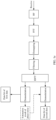
- the transmit end sequentially performs modulation (modulation), discrete Fourier transform (discrete Fourier transform, DFT), filtering (Filtering) (optional), mapping (mapping), and inverse fast Fourier transform (inverse fast Fourier transform, IFFT), and then sends a signal based on radio frequency (radio frequency, RF).
- modulation modulation
- discrete Fourier transform discrete Fourier transform
- filtering filtering
- mapping mapping
- IFFT inverse fast Fourier transform
- IFFT inverse fast Fourier transform
- the processing procedure of transmission based on a single carrier at the transmit end further includes DFT and filtering.
- DFT indicates digital Fourier transform (digital Fourier transform) that transforms a modulation symbol from time domain to frequency domain.
- Filtering indicates that filtering processing is performed on a signal, such as match filtering (match filtering).
- the receive end After receiving the signal (the first signal and the second signal) via a radio frequency unit, the receive end sequentially performs FFT, demapping, filtering, inverse discrete Fourier transform (inverse discrete Fourier transform, IDFT), and demodulation, obtains the first data based on the first signal, and obtains the second data based on the second signal.
- the processing procedure of transmission based on a single carrier at the receive end further includes filtering and IDFT. IDFT indicates that a frequency-domain signal is transformed to a time-domain signal.
- the transmit end 101 may be an entity configured to transmit a signal.
- the receive end 102 may be an entity configured to receive a signal.
- the transmit end 101 may also have a function of receiving a signal, and the receive end 102 may also have a function of sending a signal.
- Both the transmit end 101 and the receive end 102 may be a terminal device or a network device.
- the transmit end 101 is the network device and the receive end 102 is the terminal device.
- the schematic diagram of the architecture of the communication system shown in FIG. 1a may be shown in FIG. 1f
- the terminal device may be user equipment (user equipment, UE), a remote terminal, a mobile terminal, a wireless communication device, a user apparatus, a mobile station (Mobile Station, MS), a subscriber unit (subscriber unit), a cellular phone (cellular phone), a smart phone (smart phone), a wireless data card, a personal digital assistant (Personal Digital Assistant, PDA for short) computer, a tablet computer, a wireless modem (modem), a handheld device (handset), an in-vehicle device, a laptop computer (laptop computer), a machine type communication (Machine Type Communication, MTC) terminal, or the like.
- the user equipment may be a mobile phone, a desktop computer, a notebook computer, another wearable device, or the like.
- the network device may be an access network device, a core network device, or the like.
- the access network device may include various forms of macro base stations, micro base stations (also referred to as small cells), relay stations, access points, and the like.
- a fifth generation (fifth generation, 5G) communication system a new radio (new radio, NR) system of a fifth generation (fifth generation, 5G) access technology
- an NR vehicle to everything vehicle to everything, NR V2X
- a long term evolution Long Term Evolution, LTE
- 5G hybrid networking system a device-to-device (device-to-device, D2D) communication system
- a machine-to-machine (machine-to-machine, M2M) communication system an Internet of Things (Internet of Things, IoT) communication system, or an uncrewed aerial vehicle communication system.
- IoT Internet of Things
- the technologies may be further used in a communication system that supports a plurality of wireless technologies, for example, an LTE technology and an NR technology.
- the technologies may be further used in a system in which a plurality of communication systems are converged.
- the technologies may be further used in a future evolved communication system, for example, a 6G communication system.
- the technologies may be further used in a non-terrestrial communication system, for example, a satellite communication system or a high-altitude communication platform.
- the technologies may be used in the following communication systems: a narrowband internet of things (Narrowband Internet of Things, NB-IoT) system, an enhanced data rates for GSM evolution (Enhanced Data rates for GSM Evolution, EDGE) system, a wideband code division multiple access (Wideband Code Division Multiple Access, WCDMA) system, a code division multiple access 2000 (Code Division Multiple Access, CDMA 2000) system, a time division-synchronous code division multiple access (Time Division-Synchronous Code Division Multiple Access, TD-SCDMA) system, a long term evolution (Long Term Evolution, LTE) system, and a future-oriented communication technology.
- NB-IoT narrowband internet of things
- EDGE Enhanced Data rates for GSM Evolution
- WCDMA Wideband Code Division Multiple Access
- CDMA 2000 Code Division Multiple Access
- TD-SCDMA time division-synchronous code division multiple access
- LTE Long Term Evolution
- names of data, information, a signal, a parameter, and the like mentioned in embodiments of the application are used as examples.
- the names may be different in different communication systems. This is not limited in embodiments of the application.
- FIG. 2 is a schematic flowchart of a data transmission method according to an embodiment of the application. The method includes but is not limited to the following steps.
- Step S201 A transmit end determines a reference signal and a data signal, where the reference signal is for transmitting first data, the data signal is for transmitting second data, a resource element carrying the reference signal and a resource element carrying the data signal belong to a same frequency domain resource assignment, a modulation and coding parameter of the reference signal is smaller than a modulation and coding parameter of the data signal, and the modulation and coding parameter includes one or more of the following: an MCS index, a modulation order, a code rate, or spectral efficiency.
- the transmit end may process the data bit of the first data according to the procedure shown in FIG. 1b or FIG. 1d , to obtain the reference signal. Similarly, after obtaining a data bit of the second data, the transmit end may process the data bit of the second data according to the procedure shown in FIG. 1b or FIG. 1d , to obtain the data signal.
- the resource element (for example, referred to as a resource element A) carrying the reference signal and the resource element (for example, referred to as a resource element B) carrying the data signal belong to the same frequency domain resource assignment.
- This may indicate that the resource element A and the resource element B belong to a frequency domain resource of the same frequency domain resource assignment, and the same frequency domain resource is a block of frequency domain resource configured based on same control signaling.
- the control signaling may be, for example, downlink control information (downlink control information, DCI). That the resource element A and the resource element B belong to the same frequency domain resource assignment may further indicate that the resource element A and the resource element B belong to a same RB or a same scheduled bandwidth.
- the RB is a minimum scheduled unit.
- the scheduled bandwidth may be a scheduled unit of another granularity.
- the scheduled bandwidth includes a plurality of RBs.
- the scheduled bandwidth may indicate a quantity of resource blocks occupied by a PDSCH scheduled by the DCI or a quantity of consecutive resource blocks.
- That the resource element A and the resource element B belong to the same RB or the same scheduled bandwidth may indicate that a subcarrier (for example, referred to as a subcarrier 1) carrying the reference signal and a subcarrier (for example, referred to as a subcarrier 2) carrying the data signal belong to the same RB or the same scheduled bandwidth.
- the data bit of the first data may be mapped to the subcarrier 1 according to a modulation manner 1
- the data bit of the second data may be mapped to the subcarrier 2 according to a modulation manner 2.
- the modulation manner 1 and the modulation manner 2 may be the same, or may be different. This is not limited in this embodiment of the application.
- a smaller modulation and coding parameter of the signal indicates a lower signal-to-noise ratio needed for demodulating the signal at a receive end.
- the modulation and coding parameter of the reference signal is smaller than the modulation and coding parameter of the data signal, so that a lower signal-to-noise ratio is needed for demodulating the reference signal, a success rate of demodulating the reference signal at the receive end is higher, and data can be successfully transmitted based on the reference signal, thereby helping improve data transmission efficiency.
- the modulation and coding parameter of the reference signal is smaller than the modulation and coding parameter of the data signal (that is, the modulation and coding parameter of the reference signal is different from the modulation and coding parameter of the data signal), and the resource element (for example, referred to as the resource element A) carrying the reference signal and the resource element (for example, referred to as the resource element B) carrying the data signal belong to the same frequency domain resource assignment.
- This may indicate that data (that is, the first data and the second data) of different modulation and coding parameters is transmitted in a same RB or a same scheduled bandwidth. This helps improve the data transmission efficiency.
- the modulation and coding parameter of the reference signal is smaller than the modulation and coding parameter of the data signal, which indicates that at least one of an MCS index, a modulation order, a code rate, or spectral efficiency of the reference signal is smaller than a corresponding parameter of the data signal.
- an MCS index of the reference signal may be smaller than an MCS index of the data signal
- a modulation order of the reference signal may be smaller than a modulation order of the data signal
- a code rate of the reference signal may be smaller than a code rate of the data signal
- spectral efficiency of the reference signal may be smaller than spectral efficiency of the data signal.
- the MCS index of the reference signal may be smaller than the MCS index of the data signal
- the modulation order of the reference signal may be smaller than the modulation order of the data signal
- the spectral efficiency of the reference signal may be smaller than the spectral efficiency of the data signal.
- the code rate of the reference signal may be greater than or equal to the code rate of the data signal, or the code rate of the reference signal may be smaller than the code rate of the data signal.
- a modulation manner of the reference signal may include but is not limited to the following modulation manners: binary phase shift keying (binary phase shift keying, BPSK), pi/2-BPSK, quadrature phase shift keying (quadrature phase shift keying, QPSK), pi/4 QPSK, 8PSK, and 16 quadrature amplitude modulation (quadrature amplitude modulation, QAM).
- the modulation order of the reference signal may be a modulation order corresponding to the modulation manner.
- the code rate of the reference signal may be 1, that is, coding is not performed, and an original data bit is transmitted.
- the code rate of the reference signal may be greater than a first threshold, that is, the reference signal is transmitted at a high code rate.
- the first threshold may be 0.5.
- the modulation and coding parameter of the reference signal and the modulation and coding parameter of the data signal in this embodiment of the application may be values in an MCS table shown in Table 1, or may be values in another MCS table (for example, referred to as a new MCS table).
- a code rate in the new MCS table may include but is not limited to one or more of the following values: 517, 553, 526, 602, 553, 616, 658, 682.5, 711, 754, 797, 841, 885, 916.5, 567, 616, 666, 719, 772, 822, 873, 910, 948, and 1.
- a modulation order in the new MCS table may include but is not limited to one or more of modulation orders corresponding to the following modulation manners: BPSK, pi/2-BPSK, QPSK, pi/4 QPSK, 8PSK, and 16QAM.
- the modulation and coding parameter of the reference signal may be determined based on the modulation and coding parameter of the data signal.
- Manner 1 There is a one-to-one correspondence between the modulation and coding parameter of the data signal and the modulation and coding parameter of the reference signal. After the modulation and coding parameter of the data signal is determined, the modulation and coding parameter of the reference signal may be determined based on the modulation and coding parameter of the data signal and the one-to-one correspondence.
- Manner 2 There is a one-to-many relationship between the modulation and coding parameter of the data signal and the modulation and coding parameter of the reference signal.
- the modulation and coding parameter includes the MCS index.
- Table 2 shows a correspondence between the MCS index (indicated by MCS1 in Table 2) of the data signal and the MCS index (indicated by MCS2 in Table 2) of the reference signal.
- MCS index that is, MCS1
- MCS2 MCS indexes
- a value range of MCS2 corresponding to MCS1 is MCS2 ⁇ MCS21.
- a specific modulation and coding parameter to be used as the modulation and coding parameter of the reference signal may be determined from the plurality of modulation and coding parameters based on indication information from a network device.
- Table 2 Correspondence between the MCS index of the data signal and the MCS index of the reference signal MCS index (MCS1) of the data signal MCS index (MCS2) of the reference signal MCS1 ⁇ MCS11 The reference signal does not carry data.
- the modulation and coding parameter of the data signal may be determined based on the modulation and coding parameter of the reference signal.
- Manner 1 There is a one-to-one correspondence between the modulation and coding parameter of the reference signal and the modulation and coding parameter of the data signal. After the modulation and coding parameter of the reference signal is determined, the modulation and coding parameter of the data signal may be determined based on the modulation and coding parameter of the reference signal and the one-to-one correspondence.
- Manner 2 There is a one-to-many relationship between the modulation and coding parameter of the reference signal and the modulation and coding parameter of the data signal. For example, an example in which the modulation and coding parameter includes the MCS index is used. Refer to Table 3. Table 3 shows a correspondence between the MCS index (indicated by MCS2 in Table 3) of the reference signal and the MCS index (indicated by MCS1 in Table 3) of the data signal.
- MCS indexes that is, MCS1 of a plurality of data signals correspond to the MCS index of the reference signal.
- MCS11 ⁇ MCS2 ⁇ MCS12 a value range of MCS1 corresponding to MCS2 is MCS1 ⁇ MCS21.
- a specific modulation and coding parameter to be used as the modulation and coding parameter of the data signal may be determined from the plurality of modulation and coding parameters based on indication information from a network device.
- MCS11, MCS12, MCS13, ..., MCS1n may be values of the MCS indexes (that is, MCS1) of the data signals
- MCS21, MCS22, ..., MCS2n may be values of the MCS indexes (that is, MCS2) of the reference signals
- MCS11, MCS12, MCS13, ..., MCS1n may be values of the MCS indexes (that is, MCS2) of the reference signals
- MCS21, MCS22, ..., MCS2n may be values of the MCS indexes (that is, MCS1) of the data signals.
- the values of MCS11, MCS12, MCS13, ..., MCS1n, and the values of MCS21, MCS22, ..., and MCS2n may be configured by the network device, or may be reported by a terminal device, or may be agreed on in a protocol. This is not limited in this embodiment of the application.
- the protocol may be indicated by a protocol between the terminal device and the network device.
- the network device or the terminal device may agree on that the code rate of the reference signal is 1, or the network device configures the code rate of the reference signal to 1.
- the value of MCS1 and the value of MCS2 may be values of MCS indexes in a same MCS table, or may be values of MCS indexes in different MCS tables. This is not limited in this embodiment of the application.
- the value of MCS1 and the value of MCS2 may be the values of the MCS indexes in the MCS table shown in Table 1, or may be values in the new MCS table.
- the value of MCS1 and the value of MCS2 may be the values of the MCS indexes in the MCS table shown in Table 1, and in Table 3, the value of MCS1 and the value of MCS2 may be the values in the new MCS table.
- the value of MCS1 and the value of MCS2 may be the values of the MCS indexes in the MCS table shown in Table 1, and in Table 2, the value of MCS1 and the value of MCS2 may be the values in the new MCS table.
- the examples in which the modulation and coding parameters includes the MCS indexes are used.
- the MCS indexes in Table 2 and Table 3 may also be replaced with code rates, modulation orders (or modulation manners), or spectral efficiency.
- the MCS indexes in Table 2 are replaced with modulation manners.
- the modulation manner used for the data signal is 16QAM
- the modulation manner that may be used for the reference signal is QPSK
- the modulation manner used for the data signal is 64QAM
- the modulation manner used for the reference signal may be 16QAM or 8PSK.
- the correspondences shown in Table 2 and Table 3 may be configured based on radio resource control (radio resource control, RRC) signaling (or media access control control element (media access control control element, MAC-CE) signaling) and DCI signaling.
- RRC radio resource control
- MAC-CE media access control control element
- some correspondences are configured based on the RRC signaling (or the MAC-CE signaling), and the other correspondences are configured based on the DCI.
- an MCS table is configured based on the RRC signaling (or the MAC-CE signaling), and MCS1 is configured as an MCS index in the MCS table and MCS2 is configured as an MCS index in the MCS table based on the DCI.
- the MAC-CE signaling is a type of higher layer signaling transmitted on a data channel.
- the modulation and coding parameter of the reference signal may be determined based on one or more of the following parameters: the modulation and coding parameter of the data signal, a quantity of resource elements occupied by the second data, power of the second data, frequency domain density of the reference signal, time domain density of the reference signal, power of the reference signal, a quantity of reference signals, a quantity of reference signals included in a reference signal block to which the reference signal belongs, a data volume of the first data, or a quantity of reference signal blocks.
- the quantity of resource elements occupied by the second data may indicate a segment of bandwidth in frequency domain, and may indicate a period of time in time domain.
- the time domain density of the reference signal may indicate a quantity of time domain symbols on which there is one reference signal. For example, if the time domain density of the reference signal is 4, it may indicate that there is one reference signal on every four time domain symbols.
- the time domain symbol may be an OFDM symbol.
- the frequency domain density of the reference signal may indicate a quantity of RBs on which there is one reference signal.
- the quantity of reference signals may indicate a total quantity of reference signals for transmitting the first data, and the quantity may be one or more.
- One reference signal block may include one or more reference signals.
- the quantity of reference signal blocks may indicate a total quantity of reference signal blocks for transmitting the first data, and the quantity may be one or more.
- the data volume of the first data may be a quantity of bits of the first data.
- the modulation and coding parameter includes the spectral efficiency
- the spectral efficiency of the reference signal may be determined based on the quantity of reference signals and a quantity of bits of data (that is, the first data) transmitted based on the reference signal.
- the quantity of reference signals may be determined in the following manner: The quantity of reference signals is determined based on the quantity (for example, a bandwidth of the second data) of resource elements (or modulation symbols) occupied by the second data and the frequency domain density of the reference signal.
- the bandwidth of the second data is 60 RBs
- there is one reference signal RE on two RBs that is, the frequency domain density of the reference signal is 2
- duration of a transport block of a PDSCH carrying the second data is an entire slot, and one slot includes 14 symbols
- the quantity of bits of the first data is 100 bits
- a modulation manner of the reference signal is QPSK (that is, information of two bits may be transmitted based on one RE)
- the first data when the quantity of reference signals is smaller than a second threshold, or a data volume of data (that is, the first data) transmitted based on the reference signal is smaller than a third threshold, the first data may be transmitted by using a sequence, that is, the first data is not coded. Each reference signal sequence may indicate one piece of first data.
- the reference signal when the quantity of reference signals is greater than or equal to the second threshold, or a data volume of data (that is, the first data) transmitted based on the reference signal is greater than or equal to the third threshold, the reference signal (or the first data) may be transmitted at a high code rate. In this case, the data volume of the first data transmitted based on the reference signal is large, and a coding gain is high when the first data is transmitted at the high code rate.
- the modulation and coding parameter of the reference signal may be increased when the power of the reference signal is increased.
- the modulation and coding parameter of the reference signal may be increased by K.
- One MCS index may be understood as one level.
- MCS11, MCS12, MCS13, ..., and MCS1n are separately one level, and MCS11 is one level lower than MCS12.
- Values of M and K may be configured based on the RRC signaling (or the MAC-CE signaling), or may be agreed on in a protocol. This is not limited in this embodiment of the application.
- Step S202 The transmit end sends the reference signal and the data signal.
- the transmit end may send the reference signal and the data signal based on radio frequency.
- the data signal may be scheduled through a control channel, and the reference signal may be scheduled through a control channel or a data channel.
- the reference signal may be scheduled based on the DCI or the MAC-CE signaling, and the MAC-CE signaling is transmitted through a PDSCH.
- the reference signal and the data signal may be scheduled based on same DCI.
- a range of the modulation and coding parameter of the reference signal may be configured based on the RRC signaling, the range of the modulation and coding parameter of the reference signal may be configured based on the MAC-CE signaling, or the range of the modulation and coding parameter of the reference signal may be agreed on in a protocol.
- a resource block carrying the reference signal may further carry first information.
- the reference signal is transmitted based on a first transport block, and the first information is transmitted based on a second transport block.
- the reference signal may exist as an independent transport block, and other information (that is, the first information) carried in the resource block carrying the reference signal and the reference signal are transmitted based on different transport blocks. This manner helps avoid interference of the first information to the reference signal.
- the first transport block and the second transport block may be a same transport block.
- the other information (that is, the first information) carried in the resource block carrying the reference signal and the reference signal may be transmitted based on a same transport block, thereby helping reduce used transport block resources.
- That the other information (that is, the first information) carried in the resource block carrying the reference signal and the reference signal are transmitted based on a same transport block may be understood as: A subcarrier occupied by the reference signal and another subcarrier on which data is transmitted in the resource block belong to a same transport block, or the resource element occupied by the reference signal and another resource element on which data is transmitted in the resource block belong to a same transport block.
- a field may be added for scheduling the first transport block.
- a field may be added to the DCI.
- the added field is as follows:
- a scheduling parameter for scheduling the first transport block may be totally different from or partially different from a scheduling parameter for scheduling the second transport block.
- the scheduling parameter includes a modulation and coding parameter, and a modulation and coding parameter in the scheduling parameter for scheduling the first transport block is different from a modulation and coding parameter in the scheduling parameter for scheduling the second transport block.
- the transmit end may send indication information.
- the indication information indicates the modulation and coding parameter of the reference signal.
- the receive end obtains the indication information, and determines the modulation and coding parameter of the reference signal based on the indication information.
- the indication information may be DCI, RRC, or a MAC-CE.
- the indication information may explicitly indicate or implicitly indicate the modulation and coding parameter of the reference signal.
- Explicit indication means that the indication information includes the modulation and coding parameter of the reference signal.
- Implicit indication means that the indication information includes information that has a correspondence with the modulation and coding parameter of the reference signal, and the modulation and coding parameter of the reference signal may be determined based on the information and the correspondence.
- the modulation and coding parameter includes the MCS index
- the indication information includes an MCS index 1
- the indication information indicates that the MCS index of the reference signal is 2 greater than the carried MCS index 1, the MCS index of the reference signal is 3.
- the modulation and coding parameter may include at least one of the MCS index, an MCS level, the modulation order, the code rate, or the spectral efficiency.
- An example in which the modulation and coding parameter includes the MCS level is used.
- Step S203 The receive end demodulates a first signal to obtain the first data, and demodulate a second signal to obtain the second data, where the first signal includes a signal obtained after the reference signal is transmitted, and the second signal includes a signal obtained after the data signal is transmitted.
- the receive end receives the signal obtained after the reference signal is transmitted and the signal obtained after the data signal is transmitted.
- the receive end may obtain the first data by demodulating the signal obtained after the reference signal is transmitted, and may obtain the second data by demodulating the signal obtained after the data signal is transmitted.
- the reference signal is for transmitting the first data, and may be further used as a reference signal of the data signal.
- the signal (that is, the first signal) obtained after the reference signal is transmitted is demodulated, and an obtained estimation result of phase noise may be used to assist in demodulation of the signal (that is, the second signal) obtained after the data signal is transmitted.
- the receive end demodulates the first signal to obtain the estimation result of phase noise. Then, the receive end may perform phase noise compensation on the second signal based on the estimation result of phase noise to obtain the second data through demodulation.
- the reference signal mentioned in this embodiment of the application may be a phase tracking reference signal (phase tracking reference signal, PTRS), a demodulated reference signal (demodulated reference signal, DMRS), or another reference signal. This is not limited in this embodiment of the application.
- orthogonal cover code (orthogonal cover code, OCC) information may be used for transmission.
- OCC orthogonal cover code
- reference signals in a same group may occupy a same RE resource.
- reference signals corresponding to different users may be distinguished based on the OCC information.
- one OCC sequence is transmitted at N1 OCC time domain positions, and N2 users have N2 sequences.
- the two OCC sequences each include two time-frequency positions.
- the two OCC sequences are respectively [+1,+1] and [+1,-1].
- the four OCC sequences each include four time-frequency positions.
- the four OCC sequences are respectively [+1,+1,+1,+1], [+1,-1,+1,-1], [+1,+1,-1,-1], and [+1,-1,-1,+1].
- +1 and -1 in the OCC sequences each indicate a position of one resource element.
- same data may be transmitted based on the reference signal. For example, two resource elements in the OCC sequence [+1,+1] are for transmitting a same bit, and four resource elements in the OCC sequence [+1,+1,+1,+1] are for transmitting a same bit.
- a plurality of positions are for transmitting same information of the reference signal, so that a signal-to-noise ratio of information transmission can be improved.
- the orthogonal cover code (orthogonal cover code, OCC) information of the reference signal (for example, the PTRS) in this embodiment of the application may be the same as OCC information of the DMRS.
- the OCC information of the PTRS is the same as the OCC information of the DMRS, and may indicate that an OCC pattern (or referred to as a pattern) of the PTRS is the same as an OCC pattern of the DMRS. In this manner, the OCC pattern of the PTRS may not need to be separately indicated, thereby helping reduce used resources.
- the OCC pattern of the PTRS may be the same as the OCC pattern of the DMRS.
- a quantity of REs of consecutive OCC of the reference signal may be determined based on a frequency division scale of OCC of the DMRS. For example, for a DMRS4 port, the DMRS needs two REs as one group of OCC, and there are two groups of OCC in total. Therefore, four REs are needed as one block. Similarly, for the block pilot of the reference signal, two REs may also be used as one group of OCC, and there are two groups of OCC in total. Therefore, a quantity of REs in a reference signal block is 4.
- data information (that is, the first data) is transmitted based on the reference signal, thereby helping improve the data transmission efficiency.
- the modulation and coding parameter of the reference signal is smaller than the modulation and coding parameter of the data signal, so that the low signal-to-noise ratio is needed for demodulating the reference signal, the success rate of demodulating the reference signal at the receive end is high, and the data can be successfully transmitted based on the reference signal, thereby helping improve the data transmission efficiency.
- FIG. 3 is a schematic flowchart of another data transmission method according to an embodiment of the application.
- the method describes content of transmitting first data based on a plurality of reference signals.
- the method may include, but is not limited to, the following steps.
- Step S301 A transmit end determines a reference signal and a data signal, where the reference signal is for transmitting first data, the data signal is for transmitting second data, a resource element carrying the reference signal and a resource element carrying the data signal belong to a same frequency domain resource assignment, a modulation and coding parameter of the reference signal is smaller than a modulation and coding parameter of the data signal, the modulation and coding parameter includes one or more of the following: an MCS index, a modulation order, a code rate, or spectral efficiency, the reference signal includes a first reference signal and a second reference signal, a resource element carrying the first reference signal is adjacent to a resource element carrying the second reference signal in at least one of the following domains: time domain or frequency domain, the first reference signal is a reference signal having a largest modulation and coding parameter in the reference signal for transmitting the first data, and the second reference signal is a reference signal having a smallest modulation and coding parameter in the reference signal for transmitting the first data.
- the reference signal includes a
- the first data may be transmitted based on one or more reference signals.
- the first data is transmitted based on a plurality of reference signals.
- a receive end may demodulate reference signals in ascending order of modulation and coding parameters.
- an estimation result of phase noise of a reference signal carried on one of the two resource elements may be used to determine an estimation result of phase noise of a reference signal carried on the other resource element.
- a resource element 1 and a resource element 2 are adjacent in time domain, the resource element 1 carries a reference signal 1, and the resource element 2 carries a reference signal 2.
- an estimation result of phase noise of the reference signal 1 may be used to determine an estimation result of phase noise of the reference signal 2. This helps improve accuracy of the estimation result of the phase noise the reference signal 2, and helps improve phase noise estimation performance.
- the resource element carrying the first reference signal may be adjacent to the resource element carrying the second reference signal in at least one of the following domains: the time domain or the frequency domain.
- the reference signal for transmitting the first data includes at least the first reference signal and the second reference signal, and modulation and coding parameters of the reference signals for transmitting the first data may be the same or different.
- the second reference signal is the reference signal having the smallest modulation and coding parameter in the reference signal for transmitting the first data. Therefore, a lower signal-to-noise ratio is needed for demodulating the second reference signal, and a success rate of demodulating the second reference signal at the receive end is higher, so that an estimation result on phase noise of the second reference signal can be successfully obtained.
- the resource element carrying the first reference signal is adjacent to the resource element carrying the second reference signal in at least one of the following domains: time domain or frequency domain. Therefore, the estimation result on the phase noise of the second reference signal may be used to determine an estimation result on phase noise of the first reference signal. This manner helps improve accuracy of the estimation result of the phase noise of the second reference signal, and helps improve phase noise estimation performance.
- the first reference signal is the reference signal having the largest modulation and coding parameter in the reference signal for transmitting the first data
- the second reference signal is the reference signal having the smallest modulation and coding parameter in the reference signal for transmitting the first data.
- the modulation and coding parameter of the reference signal carried on the adjacent resource element in at least one of the following domains: the time domain or the frequency domain only needs to include a smaller modulation and coding parameter and a larger modulation and coding parameter. In this way, an estimation result of phase noise of a reference signal having the smaller modulation and coding parameter may be used for estimation on phase noise of a reference signal with the larger modulation and coding parameter.
- the first reference signal when the second reference signal is the reference signal having the smallest modulation and coding parameter in the reference signal for transmitting the first data, the first reference signal may also be a reference signal having a second largest modulation and coding parameter in the reference signals for transmitting the first data.
- the first data may be transmitted based on one or more reference signal blocks, and each reference signal block may include one or more reference signals.
- the first data may be transmitted based on a plurality of reference signal blocks.
- Each reference signal block may include a plurality of reference signals, and each reference signal block includes at least two reference signals that have different modulation and coding parameters. This manner helps improve efficiency of transmitting data based on the reference signal.
- the first data may be transmitted based on a first reference signal block and a second reference signal block.
- a modulation and coding parameter of the reference signal may be the same as a modulation and coding parameter of a corresponding reference signal in the second reference signal block. It may be understood that an arrangement of modulation and coding parameters of the first reference signal block is the same as that of the modulation and coding parameters of the second reference signal block. In this manner, only a modulation and coding parameter of a reference signal in one reference signal block (for example, the first reference signal block) needs to be indicated (that is, an arrangement of modulation and coding parameters of one reference signal block is indicated).
- the first reference signal block (or the second reference signal block) may include reference signals with different modulation and coding parameters, or may include reference signals with a same modulation and coding parameter.
- the modulation and coding parameters of the reference signals in the first reference signal block (or the second reference signal block) may be different or may be the same. This is not limited in this embodiment of the application.
- P indicates a modulation and coding parameter
- a number following P indicates a size of the modulation and coding parameter.
- P1 ⁇ P2 ⁇ P3 indicates that a modulation and coding parameter of a reference signal 1 is smaller than a modulation and coding parameter of a reference signal 2, and the modulation and coding parameter of the reference signal 2 is smaller than a modulation and coding parameter of a reference signal 3.
- a small block indicates a resource element carrying a reference signal.
- a known reference signal may also be replaced with a reference signal whose modulation and coding parameter (for example, a modulation and coding parameter is 0) is another value, and the known reference signal does not carry data information.
- modulation and coding parameter for example, a modulation and coding parameter is 0
- FIG. 4c arrangements of modulation and coding parameters of reference signal blocks are the same.
- reference signals are arranged in ascending order of modulation and coding parameters.
- the receive end may first estimate phase noise of a reference signal having a smaller modulation and coding parameter, and then estimate phase noise of another reference signal having a larger modulation and coding parameter.
- a modulation and coding parameter of a previous reference signal is smaller. Therefore, phase noise of a current reference signal may be estimated based on an estimation result of phase noise of the previous reference signal, thereby helping improve phase noise estimation performance.
- a resource element for example, a resource element carrying a reference signal 3 carrying a reference signal having a larger modulation and coding parameter is adjacent to a resource element (for example, a resource element carrying a reference signal 1) carrying a reference signal having a smaller modulation and coding parameter in time domain. Therefore, when phase noise estimation of the reference signal having the larger modulation and coding parameter is performed, an estimation result of phase noise of the reference signal having the smaller modulation and coding parameter may be used, thereby helping improve the phase noise estimation performance.
- a reference signal block may include reference signals having a same modulation and coding parameter, for example, a reference signal 1 and a reference signal 3, or may include reference signals having different modulation and coding parameters, for example, a reference signal 1 and a reference signal 2.
- values of P1, P2, and P3 in FIG. 4a , FIG. 4b , and FIG. 4c are not necessarily 1, 2, and 3.
- P1, P2, and P3 indicate a value relationship between modulation and coding parameters.
- the values of P1, P2, and P3 may be configured by a network device, or may be agreed on in a protocol, or may be reported by a terminal device. This is not limited in this embodiment of the application.
- an arrangement of modulation and coding parameters of reference signal blocks may be indicated in the following manners. The following manners are described by using an example in which the arrangement of the modulation and coding parameters of the reference signal blocks in FIG. 4a is indicated.
- a protocol specifies a pattern of modulation and coding parameters shown in FIG. 4a , that is, P1 ⁇ P2 ⁇ P3.
- the network device only needs to indicate the values of P1, P2, and P3.
- the values of P1, P2, and P3 may be indicated in a differential manner.
- the network device indicates values of modulation and coding parameters of all reference signals in a reference signal block.
- a protocol specifies a pattern of modulation and coding parameters shown in FIG. 4a , that is, P1 ⁇ P2 ⁇ P3, and indicates values of modulation and coding parameters of some reference signals in a reference signal block, and default values are used for modulation and coding parameters of other reference signals. For example, the values of P2 and P3 are indicated. A default value is used for P1, and the default value may be, for example, 1. The default value can be specified in the protocol.
- an arrangement of modulation and coding parameters of a first reference signal block is different from an arrangement of modulation and coding parameters of a second reference signal block.
- a modulation and coding parameter of the reference signal may be different from a modulation and coding parameter of a corresponding reference signal in the second reference signal block.
- modulation and coding parameters of the reference signals are the same as modulation and coding parameters of corresponding reference signals in the second reference signal block.
- modulation and coding parameters of the reference signals are different from modulation and coding parameters of corresponding reference signals in the second reference signal block.
- modulation and coding parameters of reference signal blocks For example, refer to two arrangement manners of modulation and coding parameters of reference signal blocks shown in FIG. 5a and FIG. 5b .
- modulation and coding parameters of a reference signal block 1 and a reference signal 2 are not totally the same.
- Pn indicates a modulation and coding parameter greater than P1.
- FIG. 5a and FIG. 5b an example in which Pn is a largest configurable modulation and coding parameter is used.
- reference signals are arranged in ascending order of modulation and coding parameters.
- the receive end may first estimate phase noise of a reference signal having a smaller modulation and coding parameter, and then estimate phase noise of another reference signal having a larger modulation and coding parameter based on an estimation result of phase noise, thereby helping improve phase noise estimation performance.
- a resource element for example, a resource element carrying a reference signal 1 carrying a reference signal having a largest modulation and coding parameter
- a resource element for example, a resource element carrying a reference signal 2
- phase noise estimation of the reference signal 1 is performed, an estimation result of phase noise of the reference signal 2 may be used, thereby helping improve the phase noise estimation performance.
- first data may be transmitted based on a third reference signal block and a fourth reference signal block.
- a modulation and coding parameter of each reference signal in the third reference signal block is a first modulation and coding parameter.
- a modulation and coding parameter of each reference signal in the fourth reference signal block is a second modulation and coding parameter.
- the third reference signal block and the fourth reference signal block each include only reference signals having a same modulation and coding parameter, and reference signals in different reference signal blocks (that is, the third reference signal block and the fourth reference signal block) have different modulation and coding parameters.
- Each reference signal block may include one or more reference signals.
- modulation and coding parameters of reference signals may be periodically arranged, and a minimum time domain unit of a period may be a reference signal.
- a period is four reference signals.
- a period is also four reference signals.
- a DFT modulation symbol block for transmitting first data includes eight reference signals.
- the DFT modulation symbol block includes two periods, and one period includes four reference signals.
- modulation and coding parameters of reference signals in time domain is used as an example.
- the modulation and coding parameters of reference signals may be alternatively arranged in frequency domain, or the modulation and coding parameters of the reference signals may be alternatively arranged in both time domain and frequency domain.
- an arrangement of modulation and coding parameters of reference signals transmitted on a first OFDM symbol is different from an arrangement of modulation and coding parameters of reference signals on another time domain symbol.
- a first reference signal on the first OFDM symbol is a known reference signal.
- modulation and coding parameters of reference signals are periodically arranged in time domain, and a period is two OFDM symbols.
- the period may be configured by a network device, agreed on between a terminal device and the network device, or may be reported by the terminal device.
- the period of two OFDM symbols is used as an example. In a specific implementation, the period may be another period. This is not limited in this embodiment of the application.
- step S301 refers to the specific description of the step S201 in FIG. 2 . Details are not described herein.
- Step S302 The transmit end sends the reference signal and the data signal.
- Step S303 The receive end demodulates a first signal to obtain the first data, and demodulate a second signal to obtain the second data, where the first signal includes a signal obtained after the reference signal is transmitted, and the second signal includes a signal obtained after the data signal is transmitted.
- step S302 and the step S303 refer to the specific descriptions of the step S202 and the step S203 in FIG. 2 . Details are not described herein again.
- data information (that is, the first data) is transmitted based on the reference signal, thereby helping improve data transmission efficiency.
- the resource element carrying the first reference signal is adj acent to the resource element carrying the second reference signal in at least one of the following domains: time domain or frequency domain, so that the estimation result on the phase noise of the second reference signal may be used to determine the estimation result on the phase noise of the first reference signal. This manner helps improve the accuracy of the estimation result of the phase noise of the second reference signal, and helps improve the phase noise estimation performance.
- the transmit end and the receive end each may include a hardware structure and a software module, to implement the functions in a form of the hardware structure, the software module, or a combination of the hardware structure and the software module.
- One of the foregoing functions may be performed through the hardware structure, the software module, or the combination of the hardware structure and the software module.
- FIG. 8 is a schematic diagram of a structure of a communication apparatus 80 according to an embodiment of the application.
- the communication apparatus 80 shown in FIG. 8 may include a processing unit 801 and a transceiver unit 802.
- the transceiver unit 802 may include a sending unit and/or a receiving unit.
- the sending unit is configured to implement a sending function
- the receiving unit is configured to implement a receiving function
- the transceiver unit 802 may implement the sending function and/or the receiving function.
- the transceiver unit may alternatively be described as a communication unit.
- the communication apparatus 80 may be a transmit end, or may be an apparatus in the transmit end, or may be an apparatus that can be used in a matching manner with the transmit end.
- the processing unit 801 is configured to determine a reference signal and a data signal.
- the reference signal is for transmitting first data.
- the data signal is for transmitting second data.
- a resource element carrying the reference signal and a resource element carrying the data signal belong to a same frequency domain resource assignment.
- the transceiver unit 802 is configured to send the reference signal and the data signal.
- a modulation and coding parameter of the reference signal is smaller than a modulation and coding parameter of the data signal.
- the modulation and coding parameter includes one or more of the following: a modulation and coding scheme MCS index, a modulation order, a code rate, or spectral efficiency.
- the modulation and coding parameter of the reference signal is determined based on the modulation and coding parameter of the data signal, or the modulation and coding parameter of the data signal is determined based on the modulation and coding parameter of the reference signal.
- the modulation and coding parameter of the reference signal is determined based on one or more of the following parameters: the modulation and coding parameter of the data signal, a quantity of resource elements occupied by the second data, power of the second data, frequency domain density of the reference signal, time domain density of the reference signal, power of the reference signal, a quantity of reference signals, a quantity of reference signals included in a reference signal block to which the reference signal belongs, or a data volume of the first data.
- the transceiver unit 802 is further configured to send indication information.
- the indication information indicates the modulation and coding parameter of the reference signal.
- a resource block carrying the reference signal further carries first information.
- the reference signal is transmitted based on a first transport block, and the first information is transmitted based on a second transport block.
- the first transport block and the second transport block are a same transport block.
- the reference signal includes a first reference signal and a second reference signal.
- a resource element carrying the first reference signal is adjacent to a resource element carrying the second reference signal in at least one of the following domains: time domain or frequency domain.
- the first reference signal is a reference signal having a largest modulation and coding parameter in the reference signal for transmitting the first data.
- the second reference signal is a reference signal having a smallest modulation and coding parameter in the reference signal for transmitting the first data.
- the first data is specifically transmitted based on a plurality of reference signal blocks.
- Each reference signal block includes a plurality of reference signals, and each reference signal block includes at least two reference signals that have different modulation and coding parameters.
- the reference signal is a phase tracking reference signal.
- the first data is specifically transmitted based on a first reference signal block and a second reference signal block.
- a modulation and coding parameter of the reference signal is the same as a modulation and coding parameter of a corresponding reference signal in the second reference signal block.
- the first data is specifically transmitted based on a third reference signal block and a fourth reference signal block.
- a modulation and coding parameter of each reference signal in the third reference signal block is a first modulation and coding parameter.
- a modulation and coding parameter of each reference signal in the fourth reference signal block is a second modulation and coding parameter.
- orthogonal cover code OCC information of the reference signal is the same as OCC information of a demodulated reference signal.
- the communication apparatus 80 When the communication apparatus 80 is the transmit end, the communication apparatus 80 is configured to implement the functions of the transmit end in the embodiments corresponding to FIG. 2 and FIG. 3 .
- the communication apparatus 80 may be a receive end, or may be an apparatus in the receive end, or may be an apparatus that can be used in a matching manner with the receive end.
- the transceiver unit 802 is configured to obtain a first signal and a second signal.
- the first signal includes a signal obtained after a reference signal is transmitted.
- the second signal includes a signal obtained after a data signal is transmitted.
- a resource element carrying the reference signal and a resource element carrying the data signal belong to a same frequency domain resource assignment.
- the processing unit 801 is configured to demodulate the first signal to obtain first data.
- the processing unit 801 is further configured to demodulate the second signal to obtain second data.
- a modulation and coding parameter of the reference signal is smaller than a modulation and coding parameter of the data signal.
- the modulation and coding parameter includes one or more of the following: a modulation and coding scheme MCS index, a modulation order, a code rate, or spectral efficiency.
- the modulation and coding parameter of the reference signal is determined based on the modulation and coding parameter of the data signal, or the modulation and coding parameter of the data signal is determined based on the modulation and coding parameter of the reference signal.
- the modulation and coding parameter of the reference signal is determined based on one or more of the following parameters: the modulation and coding parameter of the data signal, a quantity of resource elements occupied by the second data, power of the second data, frequency domain density of the reference signal, time domain density of the reference signal, power of the reference signal, a quantity of reference signals, a quantity of reference signals included in a reference signal block to which the reference signal belongs, or a data volume of the first data.
- the transceiver unit 802 is further configured to obtain indication information.
- the indication information indicates the modulation and coding parameter of the reference signal.
- a resource block carrying the reference signal further carries first information.
- the reference signal is transmitted based on a first transport block, and the first information is transmitted based on a second transport block.
- the first transport block and the second transport block are a same transport block.
- the reference signal includes a first reference signal and a second reference signal.
- a resource element carrying the first reference signal is adjacent to a resource element carrying the second reference signal in at least one of the following domains: time domain or frequency domain.
- the first reference signal is a reference signal having a largest modulation and coding parameter in the reference signal for transmitting the first data.
- the second reference signal is a reference signal having a smallest modulation and coding parameter in the reference signal for transmitting the first data.
- the first signal specifically includes a signal obtained after a reference signal in a plurality of reference signal blocks is transmitted.
- Each reference signal block includes a plurality of reference signals, and each reference signal block includes at least two reference signals that have different modulation and coding parameters.
- the reference signal is a phase tracking reference signal.
- the first signal specifically includes a signal obtained after a reference signal in a first reference signal block is transmitted and a signal obtained after a reference signal in a second reference signal block is transmitted.
- a modulation and coding parameter of the reference signal is the same as a modulation and coding parameter of a corresponding reference signal in the second reference signal block.
- the first signal specifically includes a signal obtained after a reference signal in a third reference signal block is transmitted and a signal obtained after a reference signal in a fourth reference signal block is transmitted.
- a modulation and coding parameter of each reference signal in the third reference signal block is a first modulation and coding parameter.
- a modulation and coding parameter of each reference signal in the fourth reference signal block is a second modulation and coding parameter.
- orthogonal cover code OCC information of the reference signal is the same as OCC information of a demodulated reference signal.
- the communication apparatus 80 When the communication apparatus 80 is the receive end, the communication apparatus 80 is configured to implement the functions of the receive end in the embodiments corresponding to FIG. 2 and FIG. 3 .
- FIG. 9 is a schematic diagram of a structure of another communication apparatus 90 according to an embodiment of the application.
- the communication apparatus 90 may be a transmit end or a receive end, or may be a chip, a chip system, a processor, or the like that supports the transmit end or the receive end to implement the foregoing method.
- the apparatus may be configured to implement the methods described at the transmit end or the receive end in the foregoing method embodiments. For details, refer to the descriptions in the foregoing method embodiments.
- the communication apparatus 90 may include one or more processors 901.
- the processor 901 may be a general-purpose processor, a dedicated processor, or the like.
- the processor 901 may be a baseband processor or a central processing unit.
- the baseband processor may be configured to process a communication protocol and communication data.
- the central processing unit may be configured to control a communication apparatus (for example, a base station, a baseband chip, a terminal, a terminal chip, a DU, or a CU), execute a computer program, and process data of the computer program.
- the communication apparatus 90 may further include an input/output unit.
- the input/output unit may include but is not limited to the following implementation forms: an input/output interface, a transceiver unit, a transceiver, a transceiver circuit, or the like, and is configured to implement a transceiver function.
- the input/output unit may include an input unit and an output unit.
- the input unit may be a receiver, a receiver circuit, or the like, and is configured to implement a receiving function.
- the output unit may be a transmitter, an output circuit, a transmitter circuit, or the like, and is configured to implement an output function and/or a sending function.
- the input unit and the output unit that are configured to implement the receiving function and the sending function may be separated, or may be integrated together.
- the input unit and the output unit may be configured to read and write code/data, or may be configured to transmit or transfer a signal.
- the communication apparatus 90 may include one or more memories 902.
- the memory 902 may store a computer program 903.
- the computer program may be run on the communication apparatus 90, so that the communication apparatus 90 performs the methods described in the foregoing method embodiments.
- the memory 902 may further store data.
- a dashed box 902 in FIG. 9 indicates that the memory 902 may be disposed separately, or may be integrated with the processor 901.
- the computer program 903 may be further fixed in the processor 901.
- a specific connection medium between the processor 901, the input/output unit, and the memory 902 is not limited in this embodiment of the application.
- the processor 901, the input/output unit, and the memory 902 are connected through a bus 904.
- the bus 904 is indicated by a bold line in this figure.
- a connection manner between other components is merely an example for description, and constitutes no limitation.
- the bus 904 may be classified into an address bus, a data bus, a control bus, and the like. For ease of indication, the bus is indicated by only one bold line in FIG. 9 . However, it does not indicate that there is only one bus or only one type of bus.
- the communication apparatus 90 may be the transmit end.
- the processor 901 is configured to determine a reference signal and a data signal.
- the reference signal is for transmitting first data.
- the data signal is for transmitting second data.
- a resource element carrying the reference signal and a resource element carrying the data signal belong to a same frequency domain resource assignment.
- the processor 901 is further configured to send the reference signal and the data signal.
- a modulation and coding parameter of the reference signal is smaller than a modulation and coding parameter of the data signal.
- the modulation and coding parameter includes one or more of the following: a modulation and coding scheme MCS index, a modulation order, a code rate, or spectral efficiency.
- the modulation and coding parameter of the reference signal is determined based on the modulation and coding parameter of the data signal, or the modulation and coding parameter of the data signal is determined based on the modulation and coding parameter of the reference signal.
- the modulation and coding parameter of the reference signal is determined based on one or more of the following parameters: the modulation and coding parameter of the data signal, a quantity of resource elements occupied by the second data, power of the second data, frequency domain density of the reference signal, time domain density of the reference signal, power of the reference signal, a quantity of reference signals, a quantity of reference signals included in a reference signal block to which the reference signal belongs, or a data volume of the first data.
- the processor 901 is further configured to send indication information.
- the indication information indicates the modulation and coding parameter of the reference signal.
- a resource block carrying the reference signal further carries first information.
- the reference signal is transmitted based on a first transport block, and the first information is transmitted based on a second transport block.
- the first transport block and the second transport block are a same transport block.
- the reference signal includes a first reference signal and a second reference signal.
- a resource element carrying the first reference signal is adjacent to a resource element carrying the second reference signal in at least one of the following domains: time domain or frequency domain.
- the first reference signal is a reference signal having a largest modulation and coding parameter in the reference signal for transmitting the first data.
- the second reference signal is a reference signal having a smallest modulation and coding parameter in the reference signal for transmitting the first data.
- the first data is specifically transmitted based on a plurality of reference signal blocks.
- Each reference signal block includes a plurality of reference signals, and each reference signal block includes at least two reference signals that have different modulation and coding parameters.
- the reference signal is a phase tracking reference signal.
- the first data is specifically transmitted based on a first reference signal block and a second reference signal block.
- a modulation and coding parameter of the reference signal is the same as a modulation and coding parameter of a corresponding reference signal in the second reference signal block.
- the first data is specifically transmitted based on a third reference signal block and a fourth reference signal block.
- a modulation and coding parameter of each reference signal in the third reference signal block is a first modulation and coding parameter.
- a modulation and coding parameter of each reference signal in the fourth reference signal block is a second modulation and coding parameter.
- orthogonal cover code OCC information of the reference signal is the same as OCC information of a demodulated reference signal.
- the communication apparatus 90 may be the receive end.
- the processor 901 is configured to obtain a first signal and a second signal.
- the first signal includes a signal obtained after a reference signal is transmitted.
- the second signal includes a signal obtained after a data signal is transmitted.
- a resource element carrying the reference signal and a resource element carrying the data signal belong to a same frequency domain resource assignment.
- the processor 901 is further configured to demodulate the first signal to obtain first data.
- the processor 901 is further configured to demodulate the second signal to obtain second data.
- a modulation and coding parameter of the reference signal is smaller than a modulation and coding parameter of the data signal.
- the modulation and coding parameter includes one or more of the following: a modulation and coding scheme MCS index, a modulation order, a code rate, or spectral efficiency.
- the modulation and coding parameter of the reference signal is determined based on the modulation and coding parameter of the data signal, or the modulation and coding parameter of the data signal is determined based on the modulation and coding parameter of the reference signal.
- the modulation and coding parameter of the reference signal is determined based on one or more of the following parameters: the modulation and coding parameter of the data signal, a quantity of resource elements occupied by the second data, power of the second data, frequency domain density of the reference signal, time domain density of the reference signal, power of the reference signal, a quantity of reference signals, a quantity of reference signals included in a reference signal block to which the reference signal belongs, or a data volume of the first data.
- the processor 901 is further configured to obtain indication information.
- the indication information indicates the modulation and coding parameter of the reference signal.
- a resource block carrying the reference signal further carries first information.
- the reference signal is transmitted based on a first transport block, and the first information is transmitted based on a second transport block.
- the first transport block and the second transport block are a same transport block.
- the reference signal includes a first reference signal and a second reference signal.
- a resource element carrying the first reference signal is adjacent to a resource element carrying the second reference signal in at least one of the following domains: time domain or frequency domain.
- the first reference signal is a reference signal having a largest modulation and coding parameter in the reference signal for transmitting the first data.
- the second reference signal is a reference signal having a smallest modulation and coding parameter in the reference signal for transmitting the first data.
- the first signal specifically includes a signal obtained after a reference signal in a plurality of reference signal blocks is transmitted.
- Each reference signal block includes a plurality of reference signals, and each reference signal block includes at least two reference signals that have different modulation and coding parameters.
- the reference signal is a phase tracking reference signal.
- the first signal specifically includes a signal obtained after a reference signal in a first reference signal block is transmitted and a signal obtained after a reference signal in a second reference signal block is transmitted.
- a modulation and coding parameter of the reference signal is the same as a modulation and coding parameter of a corresponding reference signal in the second reference signal block.
- the first signal specifically includes a signal obtained after a reference signal in a third reference signal block is transmitted and a signal obtained after a reference signal in a fourth reference signal block is transmitted.
- a modulation and coding parameter of each reference signal in the third reference signal block is a first modulation and coding parameter.
- a modulation and coding parameter of each reference signal in the fourth reference signal block is a second modulation and coding parameter.
- orthogonal cover code OCC information of the reference signal is the same as OCC information of a demodulated reference signal.
- the communication apparatus 90 may include a circuit, and the circuit may implement the sending, receiving, or communication function in the foregoing method embodiments.
- the processor described in the application may be implemented in the following manner: an integrated circuit (integrated circuit, IC), an analog IC, a radio frequency integrated circuit RFIC, a mixed-signal IC, an application-specific integrated circuit (application-specific integrated circuit, ASIC), a printed circuit board (printed circuit board, PCB), an electronic device, or the like.
- the processor may alternatively be manufactured by using the following IC process technology, for example, a complementary metal oxide semiconductor (complementary metal oxide semiconductor, CMOS), an n-type metal oxide semiconductor (n-type Metal oxide semiconductor, NMOS), a positive channel metal oxide semiconductor (positive channel metal oxide semiconductor, PMOS), a bipolar junction transistor (bipolar junction transistor, BJT), a bipolar CMOS (BiCMOS), silicon germanium (SiGe), gallium arsenide (GaAs), and the like.
- CMOS complementary metal oxide semiconductor
- NMOS n-type Metal oxide semiconductor
- NMOS n-type Metal oxide semiconductor
- PMOS positive channel metal oxide semiconductor
- BJT bipolar junction transistor
- BiCMOS bipolar CMOS
- SiGe silicon germanium
- GaAs gallium arsenide
- the communication apparatus in the foregoing embodiment may be a transmit end or a receive end.
- a scope of the communication apparatus described in the application is not limited thereto, and a structure of the communication apparatus may not be limited by FIG. 9 .
- the communication apparatus may be an independent device or may be a part of a large device.
- the communication apparatus may be:
- the communication apparatus may be a chip or a chip system, refer to a schematic diagram of a structure of a chip shown in FIG. 10 .
- the chip 100 shown in FIG. 10 includes a logic circuit 1001 and an input/output interface 1002. There may be one or more logic circuits 1001, and there may be a plurality of input/output interfaces 1002.
- the chip 100 is configured to implement a function of the transmit end in embodiments of the application:
- the logic circuit 1001 is configured to determine a reference signal and a data signal.
- the reference signal is for transmitting first data.
- the data signal is for transmitting second data.
- a resource element carrying the reference signal and a resource element carrying the data signal belong to a same frequency domain resource assignment.
- the input/output interface 1002 is configured to send the reference signal and the data signal.
- a modulation and coding parameter of the reference signal is smaller than a modulation and coding parameter of the data signal.
- the modulation and coding parameter includes one or more of the following: a modulation and coding scheme MCS index, a modulation order, a code rate, or spectral efficiency.
- the modulation and coding parameter of the reference signal is determined based on the modulation and coding parameter of the data signal, or the modulation and coding parameter of the data signal is determined based on the modulation and coding parameter of the reference signal.
- the modulation and coding parameter of the reference signal is determined based on one or more of the following parameters: the modulation and coding parameter of the data signal, a quantity of resource elements occupied by the second data, power of the second data, frequency domain density of the reference signal, time domain density of the reference signal, power of the reference signal, a quantity of reference signals, a quantity of reference signals included in a reference signal block to which the reference signal belongs, or a data volume of the first data.
- the input/output interface 1002 is further configured to send indication information.
- the indication information indicates the modulation and coding parameter of the reference signal.
- a resource block carrying the reference signal further carries first information.
- the reference signal is transmitted based on a first transport block, and the first information is transmitted based on a second transport block.
- the first transport block and the second transport block are a same transport block.
- the reference signal includes a first reference signal and a second reference signal.
- a resource element carrying the first reference signal is adjacent to a resource element carrying the second reference signal in at least one of the following domains: time domain or frequency domain.
- the first reference signal is a reference signal having a largest modulation and coding parameter in the reference signal for transmitting the first data.
- the second reference signal is a reference signal having a smallest modulation and coding parameter in the reference signal for transmitting the first data.
- the first data is specifically transmitted based on a plurality of reference signal blocks.
- Each reference signal block includes a plurality of reference signals, and each reference signal block includes at least two reference signals that have different modulation and coding parameters.
- the reference signal is a phase tracking reference signal.
- the first data is specifically transmitted based on a first reference signal block and a second reference signal block.
- a modulation and coding parameter of the reference signal is the same as a modulation and coding parameter of a corresponding reference signal in the second reference signal block.
- the first data is specifically transmitted based on a third reference signal block and a fourth reference signal block.
- a modulation and coding parameter of each reference signal in the third reference signal block is a first modulation and coding parameter.
- a modulation and coding parameter of each reference signal in the fourth reference signal block is a second modulation and coding parameter.
- orthogonal cover code OCC information of the reference signal is the same as OCC information of a demodulated reference signal.
- the input/output interface 1002 is configured to obtain a first signal and a second signal.
- the first signal includes a signal obtained after a reference signal is transmitted.
- the second signal includes a signal obtained after a data signal is transmitted.
- a resource element carrying the reference signal and a resource element carrying the data signal belong to a same frequency domain resource assignment.
- the logic circuit 1001 is configured to demodulate the first signal to obtain first data.
- the logic circuit 1001 is further configured to demodulate the second signal to obtain second data.
- a modulation and coding parameter of the reference signal is smaller than a modulation and coding parameter of the data signal.
- the modulation and coding parameter includes one or more of the following: a modulation and coding scheme MCS index, a modulation order, a code rate, or spectral efficiency.
- the modulation and coding parameter of the reference signal is determined based on the modulation and coding parameter of the data signal, or the modulation and coding parameter of the data signal is determined based on the modulation and coding parameter of the reference signal.
- the modulation and coding parameter of the reference signal is determined based on one or more of the following parameters: the modulation and coding parameter of the data signal, a quantity of resource elements occupied by the second data, power of the second data, frequency domain density of the reference signal, time domain density of the reference signal, power of the reference signal, a quantity of reference signals, a quantity of reference signals included in a reference signal block to which the reference signal belongs, or a data volume of the first data.
- the input/output interface 1002 is further configured to obtain indication information.
- the indication information indicates the modulation and coding parameter of the reference signal.
- a resource block carrying the reference signal further carries first information.
- the reference signal is transmitted based on a first transport block, and the first information is transmitted based on a second transport block.
- the first transport block and the second transport block are a same transport block.
- the reference signal includes a first reference signal and a second reference signal.
- a resource element carrying the first reference signal is adjacent to a resource element carrying the second reference signal in at least one of the following domains: time domain or frequency domain.
- the first reference signal is a reference signal having a largest modulation and coding parameter in the reference signal for transmitting the first data.
- the second reference signal is a reference signal having a smallest modulation and coding parameter in the reference signal for transmitting the first data.
- the first signal specifically includes a signal obtained after a reference signal in a plurality of reference signal blocks is transmitted.
- Each reference signal block includes a plurality of reference signals, and each reference signal block includes at least two reference signals that have different modulation and coding parameters.
- the reference signal is a phase tracking reference signal.
- the first signal specifically includes a signal obtained after a reference signal in a first reference signal block is transmitted and a signal obtained after a reference signal in a second reference signal block is transmitted.
- a modulation and coding parameter of the reference signal is the same as a modulation and coding parameter of a corresponding reference signal in the second reference signal block.
- the first signal specifically includes a signal obtained after a reference signal in a third reference signal block is transmitted and a signal obtained after a reference signal in a fourth reference signal block is transmitted.
- a modulation and coding parameter of each reference signal in the third reference signal block is a first modulation and coding parameter.
- a modulation and coding parameter of each reference signal in the fourth reference signal block is a second modulation and coding parameter.
- orthogonal cover code OCC information of the reference signal is the same as OCC information of a demodulated reference signal.
- the chip further includes a memory 1003, and the memory 1003 is configured to store a necessary computer program and necessary data.
- the memory 1003 may be disposed separately, or may be integrated with the logic circuit 1001, as shown in a dashed box 1003 in FIG. 10 .
- the application further provides a computer-readable storage medium.
- the computer-readable storage medium stores a computer program.
- the computer program includes program instructions. When the program instructions are executed by a computer, a function in any one of the foregoing method embodiments is implemented.
- the computer-readable storage medium includes but is not limited to a flash memory, a hard disk, and a solid-state drive.
- the application further provides a computer program product.
- the computer program product includes a computer program or instructions. When the computer program or the instructions is/are executed by a computer, a function in any one of the foregoing method embodiments is implemented.
- some optional features in embodiments of the application may be independently implemented without depending on another feature, for example, a solution on which the optional features are currently based, to resolve a corresponding technical problem and achieve corresponding effect.
- the optional features are combined with other features based on requirements.
- the apparatus provided in embodiments of the application may also correspondingly implement these features or functions. Details are not described herein.
- All or some of the foregoing embodiments may be implemented by using software, hardware, firmware, or any combination thereof.
- software is used to implement the embodiments, all or some of the embodiments may be implemented in a form of a computer program product.
- the computer program product includes one or more computer programs.
- the computer program is loaded and executed on the computer, the procedure or functions according to embodiments of the application are all or partially generated.
- the computer may be a general-purpose computer, a dedicated computer, a computer network, or other programmable apparatuses.
- the computer program may be stored in a computer-readable storage medium or may be transmitted from a computer-readable storage medium to another computer-readable storage medium.
- the computer program may be transmitted from a website, computer, server, or data center to another website, computer, server, or data center in a wired (for example, a coaxial cable, an optical fiber, or a digital subscriber line (digital subscriber line, DSL)) or wireless (for example, infrared, radio, or microwave) manner.
- the computer-readable storage medium may be any usable medium accessible by the computer, or a data storage device, for example, a server or a data center, integrating one or more usable media.
- the usable medium may be a magnetic medium (for example, a floppy disk, a hard disk, or a magnetic tape), an optical medium (for example, a high-density digital video disc (digital video disc, DVD)), a semiconductor medium (for example, a solid-state drive (solid-state drive, SSD)), or the like.
- a magnetic medium for example, a floppy disk, a hard disk, or a magnetic tape
- an optical medium for example, a high-density digital video disc (digital video disc, DVD)
- a semiconductor medium for example, a solid-state drive (solid-state drive, SSD)
- an "embodiment” mentioned throughout this specification means that particular features, structures, or characteristics related to this embodiment are included in at least one embodiment of the application. Therefore, embodiments in the entire specification do not necessarily refer to a same embodiment. In addition, these particular features, structures, or characteristics may be combined in one or more embodiments by using any appropriate manner. It may be understood that sequence numbers of the foregoing processes do not mean an execution sequence in various embodiments of the application. The execution sequence of the processes should be determined based on functions and internal logic of the processes, and should not be construed as any limitation on the implementation processes of embodiments of the application.
- system and "network” may be used interchangeably in this specification.
- network may be used interchangeably in this specification.
- the term "and/or" in this specification describes only an association relationship between associated objects and represents that three relationships may exist.
- a and/or B may represent the following three cases: Only A exists, both A and B exist, and only B exists.
- A may be singular or plural, and B may be singular or plural.
- the correspondences shown in the tables in the application may be configured, or may be predefined. Values of the information in the tables are merely examples, and other values may be configured. This is not limited in the application. When a correspondence between the information and the parameters is configured, not all the correspondences shown in the tables need to be configured. For example, in the tables in the application, correspondences shown in some rows may alternatively not be configured. For another example, proper deformations and adjustments such as splitting and combination may be performed based on the foregoing tables. Names of the parameters shown in titles of the foregoing tables may alternatively be other names that can be understood by a communication apparatus, and values or representation manners of the parameters may alternatively be other values or representation manners that can be understood by the communication apparatus.
- another data structure such as an array, a queue, a container, a stack, a linear table, a pointer, a linked list, a tree, a graph, a structure, a class, a pile, or a hash table, may alternatively be used.
- Predefine in the application may be understood as “define”, “predefine”, “store”, “pre-store”, “pre-negotiate”, “pre-configure”, “solidify”, or “pre-burn”.
Landscapes
- Engineering & Computer Science (AREA)
- Signal Processing (AREA)
- Computer Networks & Wireless Communication (AREA)
- Quality & Reliability (AREA)
- Mobile Radio Communication Systems (AREA)
- Digital Transmission Methods That Use Modulated Carrier Waves (AREA)
Applications Claiming Priority (2)
| Application Number | Priority Date | Filing Date | Title |
|---|---|---|---|
| CN202111212805.9A CN115996467A (zh) | 2021-10-18 | 2021-10-18 | 一种数据传输方法及其装置 |
| PCT/CN2022/124935 WO2023066117A1 (zh) | 2021-10-18 | 2022-10-12 | 一种数据传输方法及其装置 |
Publications (2)
| Publication Number | Publication Date |
|---|---|
| EP4387150A1 true EP4387150A1 (de) | 2024-06-19 |
| EP4387150A4 EP4387150A4 (de) | 2025-02-19 |
Family
ID=85993974
Family Applications (1)
| Application Number | Title | Priority Date | Filing Date |
|---|---|---|---|
| EP22882727.5A Pending EP4387150A4 (de) | 2021-10-18 | 2022-10-12 | Datenübertragungsverfahren und -vorrichtung |
Country Status (3)
| Country | Link |
|---|---|
| EP (1) | EP4387150A4 (de) |
| CN (1) | CN115996467A (de) |
| WO (1) | WO2023066117A1 (de) |
Families Citing this family (3)
| Publication number | Priority date | Publication date | Assignee | Title |
|---|---|---|---|---|
| CN118631386A (zh) * | 2024-05-21 | 2024-09-10 | 华为技术有限公司 | 通信方法及装置 |
| CN121604136A (zh) * | 2024-08-23 | 2026-03-03 | 华为技术有限公司 | 通信方法和装置 |
| CN120880856B (zh) * | 2025-09-23 | 2025-12-09 | 苏州门海微电子科技有限公司 | 电力线载波目标数据调制方法、装置、存储介质及芯片 |
Family Cites Families (10)
| Publication number | Priority date | Publication date | Assignee | Title |
|---|---|---|---|---|
| US20080112512A1 (en) * | 2006-11-15 | 2008-05-15 | Qualcomm Incorporated | Transmitted reference signaling scheme |
| CN104980247B (zh) * | 2014-04-04 | 2019-11-22 | 北京三星通信技术研究有限公司 | 自适应调整调制编码方式和参考信号图样的方法、基站、终端和系统 |
| CN108809601B (zh) * | 2017-05-04 | 2023-10-24 | 华为技术有限公司 | 无线通信方法及装置 |
| CN112995083B (zh) * | 2017-06-13 | 2022-03-29 | 华为技术有限公司 | 一种信息传输方法和装置 |
| CN109600827A (zh) * | 2017-09-30 | 2019-04-09 | 中兴通讯股份有限公司 | 一种参考信号的功率配置方法及装置 |
| BR112020023701A2 (pt) * | 2018-05-23 | 2021-02-09 | Ntt Docomo, Inc. | terminal, método de radiocomunicação, estação base e sistema |
| CN111262807B (zh) * | 2018-11-30 | 2021-07-16 | 华为技术有限公司 | 一种数据流复用的方法及终端 |
| US12095690B2 (en) * | 2019-01-07 | 2024-09-17 | Apple Inc. | Phase tracking reference signal design for single carrier waveform |
| WO2020261463A1 (ja) * | 2019-06-26 | 2020-12-30 | 株式会社Nttドコモ | 端末 |
| WO2021189216A1 (zh) * | 2020-03-23 | 2021-09-30 | 华为技术有限公司 | 参考信号设置方法及装置 |
-
2021
- 2021-10-18 CN CN202111212805.9A patent/CN115996467A/zh active Pending
-
2022
- 2022-10-12 WO PCT/CN2022/124935 patent/WO2023066117A1/zh not_active Ceased
- 2022-10-12 EP EP22882727.5A patent/EP4387150A4/de active Pending
Also Published As
| Publication number | Publication date |
|---|---|
| CN115996467A (zh) | 2023-04-21 |
| EP4387150A4 (de) | 2025-02-19 |
| WO2023066117A1 (zh) | 2023-04-27 |
Similar Documents
| Publication | Publication Date | Title |
|---|---|---|
| US11750423B2 (en) | Common phase error and/or inter-carrier interference | |
| EP4387150A1 (de) | Datenübertragungsverfahren und -vorrichtung | |
| EP3618337A1 (de) | Drahtloskommunikationsverfahren und -vorrichtung | |
| CN109586868B (zh) | 信息传输方法、装置、发送设备及计算机可读存储介质 | |
| CN108809598A (zh) | 一种通信方法及装置 | |
| EP3930230B1 (de) | Verfahren zur datenübertragung und kommunikationsvorrichtung | |
| CN108123738B (zh) | 一种用于动态调度的ue、基站中的方法和设备 | |
| US20110064041A1 (en) | Apparatus and Method for Allocation of Subcarriers in Clustered DFT-Spread-OFDM | |
| WO2017092697A1 (zh) | 通信系统中处理通信信号的方法和装置 | |
| US20240106616A1 (en) | Multi-user communication method and related communication apparatus | |
| US10999108B2 (en) | Wireless communication method, apparatus, and system | |
| EP4373040A1 (de) | Kommunikationsverfahren und zugehörige vorrichtung | |
| CN120345204A (zh) | 用于索引调制的装置、方法、以及计算机程序 | |
| WO2022228117A1 (zh) | 一种确定ptrs图案的方法和装置 | |
| EP3583815A1 (de) | Pilotsignale | |
| US20250300782A1 (en) | Demodulation reference signal (dmrs) transmission method, and apparatus | |
| CN117882343A (zh) | 时域资源分配方法、装置、设备及存储介质 | |
| CN114697166A (zh) | 相位噪声的估计方法、装置及系统 | |
| CN114073150B (zh) | 控制信道传输方法及装置 | |
| CN115150234A (zh) | 一种相位噪声的确定方法及相关装置 | |
| US20250007765A1 (en) | Transform-precoding of a selective set of data for transmission over a wireless communication network | |
| CN116938661A (zh) | 一种信号传输方法及装置 | |
| EP4712389A1 (de) | Verfahren und vorrichtung zur konfiguration von modulationsparametern des orthogonalen zeitfrequenzraums (otfs) | |
| US20260019311A1 (en) | Communication method and apparatus | |
| EP4510514A1 (de) | Kommunikationsverfahren und -vorrichtung |
Legal Events
| Date | Code | Title | Description |
|---|---|---|---|
| STAA | Information on the status of an ep patent application or granted ep patent |
Free format text: STATUS: THE INTERNATIONAL PUBLICATION HAS BEEN MADE |
|
| PUAI | Public reference made under article 153(3) epc to a published international application that has entered the european phase |
Free format text: ORIGINAL CODE: 0009012 |
|
| STAA | Information on the status of an ep patent application or granted ep patent |
Free format text: STATUS: REQUEST FOR EXAMINATION WAS MADE |
|
| 17P | Request for examination filed |
Effective date: 20240314 |
|
| AK | Designated contracting states |
Kind code of ref document: A1 Designated state(s): AL AT BE BG CH CY CZ DE DK EE ES FI FR GB GR HR HU IE IS IT LI LT LU LV MC ME MK MT NL NO PL PT RO RS SE SI SK SM TR |
|
| DAV | Request for validation of the european patent (deleted) | ||
| DAX | Request for extension of the european patent (deleted) | ||
| A4 | Supplementary search report drawn up and despatched |
Effective date: 20250116 |
|
| RIC1 | Information provided on ipc code assigned before grant |
Ipc: H04L 27/26 20060101ALI20250110BHEP Ipc: H04L 1/00 20060101ALI20250110BHEP Ipc: H04W 72/04 20230101ALI20250110BHEP Ipc: H04L 5/00 20060101AFI20250110BHEP |