EP4387003A1 - Vehicle wire harness and straddled vehicle including the same - Google Patents
Vehicle wire harness and straddled vehicle including the same Download PDFInfo
- Publication number
- EP4387003A1 EP4387003A1 EP23196512.0A EP23196512A EP4387003A1 EP 4387003 A1 EP4387003 A1 EP 4387003A1 EP 23196512 A EP23196512 A EP 23196512A EP 4387003 A1 EP4387003 A1 EP 4387003A1
- Authority
- EP
- European Patent Office
- Prior art keywords
- electric wire
- terminal
- vehicle
- middle portion
- connector
- Prior art date
- Legal status (The legal status is an assumption and is not a legal conclusion. Google has not performed a legal analysis and makes no representation as to the accuracy of the status listed.)
- Withdrawn
Links
Images





Classifications
-
- H—ELECTRICITY
- H01—ELECTRIC ELEMENTS
- H01R—ELECTRICALLY-CONDUCTIVE CONNECTIONS; STRUCTURAL ASSOCIATIONS OF A PLURALITY OF MUTUALLY-INSULATED ELECTRICAL CONNECTING ELEMENTS; COUPLING DEVICES; CURRENT COLLECTORS
- H01R13/00—Details of coupling devices of the kinds covered by groups H01R12/70 or H01R24/00 - H01R33/00
- H01R13/46—Bases; Cases
- H01R13/533—Bases, cases made for use in extreme conditions, e.g. high temperature, radiation, vibration, corrosive environment, pressure
-
- B—PERFORMING OPERATIONS; TRANSPORTING
- B62—LAND VEHICLES FOR TRAVELLING OTHERWISE THAN ON RAILS
- B62J—CYCLE SADDLES OR SEATS; AUXILIARY DEVICES OR ACCESSORIES SPECIALLY ADAPTED TO CYCLES AND NOT OTHERWISE PROVIDED FOR, e.g. ARTICLE CARRIERS OR CYCLE PROTECTORS
- B62J11/00—Supporting arrangements specially adapted for fastening specific devices to cycles, e.g. supports for attaching maps
- B62J11/10—Supporting arrangements specially adapted for fastening specific devices to cycles, e.g. supports for attaching maps for mechanical cables, hoses, pipes or electric wires, e.g. cable guides
-
- B—PERFORMING OPERATIONS; TRANSPORTING
- B62—LAND VEHICLES FOR TRAVELLING OTHERWISE THAN ON RAILS
- B62J—CYCLE SADDLES OR SEATS; AUXILIARY DEVICES OR ACCESSORIES SPECIALLY ADAPTED TO CYCLES AND NOT OTHERWISE PROVIDED FOR, e.g. ARTICLE CARRIERS OR CYCLE PROTECTORS
- B62J45/00—Electrical equipment arrangements specially adapted for use as accessories on cycles, not otherwise provided for
-
- H—ELECTRICITY
- H01—ELECTRIC ELEMENTS
- H01R—ELECTRICALLY-CONDUCTIVE CONNECTIONS; STRUCTURAL ASSOCIATIONS OF A PLURALITY OF MUTUALLY-INSULATED ELECTRICAL CONNECTING ELEMENTS; COUPLING DEVICES; CURRENT COLLECTORS
- H01R13/00—Details of coupling devices of the kinds covered by groups H01R12/70 or H01R24/00 - H01R33/00
- H01R13/56—Means for preventing chafing or fracture of flexible leads at outlet from coupling part
- H01R13/565—Torsion-relieving
-
- H—ELECTRICITY
- H01—ELECTRIC ELEMENTS
- H01R—ELECTRICALLY-CONDUCTIVE CONNECTIONS; STRUCTURAL ASSOCIATIONS OF A PLURALITY OF MUTUALLY-INSULATED ELECTRICAL CONNECTING ELEMENTS; COUPLING DEVICES; CURRENT COLLECTORS
- H01R13/00—Details of coupling devices of the kinds covered by groups H01R12/70 or H01R24/00 - H01R33/00
- H01R13/58—Means for relieving strain on wire connection, e.g. cord grip, for avoiding loosening of connections between wires and terminals within a coupling device terminating a cable
- H01R13/5804—Means for relieving strain on wire connection, e.g. cord grip, for avoiding loosening of connections between wires and terminals within a coupling device terminating a cable comprising a separate cable clamping part
-
- H—ELECTRICITY
- H01—ELECTRIC ELEMENTS
- H01R—ELECTRICALLY-CONDUCTIVE CONNECTIONS; STRUCTURAL ASSOCIATIONS OF A PLURALITY OF MUTUALLY-INSULATED ELECTRICAL CONNECTING ELEMENTS; COUPLING DEVICES; CURRENT COLLECTORS
- H01R13/00—Details of coupling devices of the kinds covered by groups H01R12/70 or H01R24/00 - H01R33/00
- H01R13/46—Bases; Cases
- H01R13/502—Bases; Cases composed of different pieces
-
- H—ELECTRICITY
- H01—ELECTRIC ELEMENTS
- H01R—ELECTRICALLY-CONDUCTIVE CONNECTIONS; STRUCTURAL ASSOCIATIONS OF A PLURALITY OF MUTUALLY-INSULATED ELECTRICAL CONNECTING ELEMENTS; COUPLING DEVICES; CURRENT COLLECTORS
- H01R2201/00—Connectors or connections adapted for particular applications
- H01R2201/26—Connectors or connections adapted for particular applications for vehicles
-
- H—ELECTRICITY
- H01—ELECTRIC ELEMENTS
- H01R—ELECTRICALLY-CONDUCTIVE CONNECTIONS; STRUCTURAL ASSOCIATIONS OF A PLURALITY OF MUTUALLY-INSULATED ELECTRICAL CONNECTING ELEMENTS; COUPLING DEVICES; CURRENT COLLECTORS
- H01R24/00—Two-part coupling devices, or either of their cooperating parts, characterised by their overall structure
- H01R24/28—Coupling parts carrying pins, blades or analogous contacts and secured only to wire or cable
Definitions
- the present invention relates to a vehicle wire harness and a straddled vehicle including the same.
- a wire harness is used in a vehicle such as a straddled vehicle or the like (see, for example, Patent Literature 1 ( JP2022-72967A )).
- a known wire harness includes an electric wire, a terminal crimped to a tip portion of the electric wire, and a connector having the terminal inserted thereto.
- Patent Literature 1 JP2022-72967A
- FIG. 11 there may be a case where an electric wire 101 is sharply bent in the vicinity of a connector 103 in the case where the wire harness is installed at a certain position. In this case, a restoring force Fa against the bending is generated in the electric wire 101. Therefore, a terminal 102 crimped to a tip portion of the electric wire 101 receives a force Fb from the electric wire 101. In the case where the wire harness is connected with another wire harness, the terminal 102 is in contact with a terminal 102B of the another wire harness. A contact pressure is generated between the terminal 102 and the terminal 102B.
- the leaf spring portion 102b exerts a spring force, and therefore, presses the terminal 102 strongly.
- the contact pressure received by the terminal 102 from the terminal 102B increases or decreases locally.
- the contact pressure on the terminal 102 may possibly increase or decrease.
- the vehicle wire harness vibrates while the vehicle is running.
- the contact pressure on the terminal 102 increases or decreases while the vehicle is running even though the pressure is favorable while the vehicle is at a stop.
- it is preferred that the contact pressure on the terminal 102 is kept favorable even while the vehicle is running.
- the present invention made in light of such a point has an object of providing a vehicle wire harness that hardly needs to be restricted regarding the position thereof and is capable of maintaining a favorable connection with another wire harness even while the vehicle is running, and a straddled vehicle including such a vehicle wire harness.
- the vehicle wire harness disclosed herein includes a first terminal; a first electric wire including a first tip portion having the first terminal crimped thereto and a first middle portion contiguous to the first tip portion; a connector having a first insertion opening opened in a first direction formed therein, and having the first terminal inserted thereto; and a first electric wire guide located further in the first direction than the first insertion opening of the connector, the first electric wire guide guiding the first middle portion of the first electric wire such that the first middle portion extends in the first direction.
- the first middle portion contiguous to the first tip portion is guided by the first electric wire guide to extend in the first direction. Therefore, the first terminal crimped to the first tip portion is unlikely to receive a force in a direction perpendicular to the first direction from the first electric wire.
- a contact pressure received by the first terminal from another terminal while the first termina is connected with the another terminal (hereinafter, such a pressure will be referred to as a "contact pressure on the first terminal") is kept favorable.
- the above-described vehicle wire harness maintains a favorable connection with another wire harness including the another terminal even while the vehicle is running.
- the above-described wire harness tolerates the bending of the first electric wire in the vicinity of the connector. Therefore, there is little need to restrict the position where the wire harness may be installed.
- the connector may have a connection opening, opened in a direction opposite to the first direction, formed therein.
- the first terminal may be configured to overlap another terminal connected thereto via the connection opening, the first terminal overlapping the another terminal in a second direction perpendicular to the first direction.
- the first terminal of the vehicle wire harness and the another terminal of the another vehicle wire harness overlap in the direction perpendicular to the first direction, and thus are electrically connected with each other.
- the first terminal is unlikely to receive a force in the direction perpendicular to the first direction from the first electric wire. This allows the contact pressure on the first terminal to be kept favorable.
- the first electric wire guide may be configured to suppress movement of the first middle portion of the first electric wire in the second direction.
- the connector may have a connection opening, opened in a direction opposite to the first direction, formed therein.
- the first terminal may include a leaf spring portion providing another terminal, connected thereto via the connection opening, with a pressing force in a direction perpendicular to the first direction.
- the vehicle wire harness may further include a first band securing the first middle portion of the first electric wire to the first electric wire guide.
- the first middle portion of the first electric wire is firmly secured to the first electric wire guide. This allows the contact pressure on the first terminal to be kept favorable.
- the first electric wire guide may include a portion having an arc-shaped cross-section taken along a direction perpendicular to the first direction.
- the first electric wire guide may include a semicylindrical portion extending in the first direction.
- the first electric wire guide guides the first middle portion of the first electric wire favorably.
- the first electric wire guide may include a guide main body supporting the first middle portion of the first electric wire, and one or a plurality of ribs provided on the guide main body and extending in the first direction.
- the first electric wire guide guides the first middle portion of the first electric wire favorably.
- the size of the first terminal in a second direction perpendicular to the first direction may be shorter than the size of the first terminal in a third direction perpendicular to the first direction and the second direction.
- the first electric wire guide and the first middle portion of the first electric wire may be adjacent to each other in the second direction.
- the size of a terminal in the second direction is shorter than the size of the terminal in the third direction, there is a tendency that when such a terminal receives a force in the second direction, the contact pressure on the terminal applied from another terminal is increased or decreased.
- the first electric wire guide and the first middle portion of the first electric wire are adjacent to each other in the second direction. Therefore, the force applied to the first middle portion in the second direction is received by the first electric wire guide. Thus, the first terminal is unlikely to receive the force in the second direction. This allows the contact pressure on the first terminal to be kept favorable.
- the connector may have a second insertion opening opened in the first direction formed therein.
- the vehicle wire harness may further include a second terminal inserted into the second insertion opening, a second electric wire including a second tip portion having the second terminal crimped thereto and a second middle portion contiguous to the second tip portion), and a second electric wire guide located further in the first direction than the second insertion opening of the connector, the second electric wire guide guiding the second middle portion of the second electric wire such that the second middle portion extends in the first direction.
- the first electric wire guide and the first middle portion of the first electric wire may be adjacent to each other in a second direction perpendicular to the first direction.
- the second electric wire guide and the second middle portion of the second electric wire may be adjacent to each other in the second direction.
- the contact pressure on the first terminal and a contact pressure on the second terminal are kept favorable.
- the restriction on the position where the vehicle wire harness may be installed is alleviated, and a favorable connection with another vehicle wire harness while the vehicle is running is realized.
- the vehicle wire harness may include a cover including the first electric wire guide, the cover being separate from the connector.
- the cover may be attached to the connector.
- the vehicle wire harness may include a cover including the first electric wire guide and the second electric wire guide, the cover being separate from the connector.
- the cover may be attached to the connector.
- attaching the cover to the connector results in the first electric wire guide and the second electric wire guide being located at appropriate positions.
- the first electric wire may have an outer diameter of 3 to 6 mm.
- the straddled vehicle disclosed herein includes the above-described vehicle wire harness.
- the straddled vehicle may include the above-described vehicle wire harness; and another vehicle wire harness including another terminal, another electric wire having the another terminal crimped thereto, and another connector having the another terminal inserted thereto.
- the connector may have a connection opening, opened in a direction opposite to the first direction, formed therein.
- the another terminal may be connected with the first terminal via the connection opening by the connector and the another connector being connected with each other.
- the first terminal and the another terminal may overlap each other in a second direction perpendicular to the first direction.
- the first electric wire guide may be configured to suppress movement of the first middle portion of the first electric wire in the second direction.
- the straddled vehicle may further include a controller, a motor, and a power supply circuit connecting the controller and the motor to each other.
- the vehicle wire harness may be included in the power supply circuit.
- the straddled vehicle may be a motorcycle.
- the present invention provides a vehicle wire harness that hardly needs to be restricted regarding the position thereof and is capable of maintaining a favorable connection with another wire harness even while the vehicle is running, and a straddled vehicle including such a vehicle wire harness.
- FIG. 1 is a side view of a motorcycle 1 as an example of a straddled vehicle.
- the motorcycle 1 includes a vehicle frame 5, a seat 9 on which a rider sits, a front wheel 6, a rear wheel 7, an internal combustion engine 8 as an example of a driving source for running, and a handle 11.
- the vehicle frame 5 includes a head pipe 3, and a main frame 4 extending rearward from the head pipe 3.
- a steering shaft 10 is supported by the head pipe 3 so as to be rotatable leftward and rightward.
- the handle 11 is connected with the steering shaft 10.
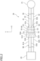
- the motorcycle 1 includes a controller 20 connected with a battery (not shown), a motor 21, and a power supply circuit 25 connecting the controller 20 and the motor 21 to each other.
- the power supply circuit 25 supplies electric power from the controller 20 to the motor 21.
- the power supply circuit 25 includes a wire harness 90 and a wire harness 30 connected with the wire harness 90.
- the wire harness 90 is directly or indirectly connected with the controller 20.
- the wire harness 30 is directly or indirectly connected with the motor 21.
- the wire harness 90 includes an electric wire 41A, an electric wire 42A, an electric wire 43A, a terminal 51A crimped to the electric wire 41A, a terminal 52A crimped to the electric wire 42A, a terminal 53A crimped to the electric wire 43A, and a connector 55A having the terminals 51A through 53A inserted thereto.
- the wire harness 30 includes a first electric wire 41, a second electric wire 42 and a third electric wire 43.
- the wire harness 30 includes a first terminal 51 crimped to the first electric wire 41, a second terminal 52 crimped to the second electric wire 42, and a third terminal 53 crimped to the third electric wire 43.
- the wire harness 30 includes a connector 55 having the first terminal 51, the second terminal 52 and the third terminal 53 inserted thereto, and a cover 60 attached to the connector 55.
- FIG. 3 is a perspective view of the first electric wire 41 and the first terminal 51.
- the first electric wire 41 includes a plurality of core wires 45 formed of a conductive material such as a metal material or the like, and a cylindrical covering member 46 surrounding the core wires 45.
- the covering member 46 is formed of an insulating material such as a resin or the like.
- the second electric wire 42 and the third electric wire 43 each have substantially the same structure as that of the first electric wire 41. It should be noted that there is no specific limitation on the structure of the first electric wire 41, the second electric wire 42 or the third electric wire 43. There is no specific limitation on the size of the first electric wire 41, the second electric wire 42 or the third electric wire 43, either.
- the first electric wire 41, the second electric wire 42 and the third electric wire 43 each have an outer diameter D40 of 3 to 6 mm.
- the first electric wire 41 includes a first tip portion 41a having the first terminal 51 crimped thereto, and a first middle portion 41b contiguous to the first tip portion 41a.
- the second electric wire 42 includes a second tip portion 42a having the second terminal 52 crimped thereto, and a second middle portion 42b contiguous to the second tip portion 42a.
- the third electric wire 43 includes a third tip portion 43a having the third terminal 53 crimped thereto, and a third middle portion 43b contiguous to the third tip portion 43a.
- the first middle portion 41b, the second middle portion 42b and the third middle portion 43b each have a length of, for example, 3 cm.
- the first terminal 51 and the first middle portion 41b of the first electric wire 41 are aligned in a first direction X.
- the second terminal 52 and the second middle portion 42b of the second electric wire 42 are also aligned in the first direction X.
- the third terminal 53 and the third middle portion 43b of the third electric wire 43 are also aligned in the first direction X.
- the first middle portion 41b of the first electric wire 41, the second middle portion 42b of the second electric wire 42, and the third middle portion 43b of the third electric wire 43 are aligned in a second direction Y perpendicular to the first direction X.
- the third middle portion 43b of the third electric wire 43 is located between the first middle portion 41b of the first electric wire 41 and the second middle portion 42b of the second electric wire 42.
- the first terminal 51, the second terminal 52 and the third terminal 53 are formed of a conductive material such as a metal material or the like.
- the first terminal 51, the second terminal 52 and the third terminal 53 are aligned in the second direction Y.
- the third terminal 53 is located between the first terminal 51 and the second terminal 52.
- a direction perpendicular to the first direction X and the second direction Y will be referred to as a third direction Z.
- Size LY of the first terminal 51 in the second direction Y is shorter than size LZ of the first terminal 51 in the third direction Z.
- the first terminal 51 is formed to be like a thin plate.
- the second terminal 52 and the third terminal 53 each have substantially the same structure as that of the first terminal 51. It should be noted that there is no specific limitation on the structure of the first terminal 51, the second terminal 52 or the third terminal 53.
- FIG. 4 is a perspective view of the connector 55.
- the connector 55 is formed of an insulating material such as a resin or the like.
- the connector 55 has a first insertion opening 56, a second insertion opening 57 and a third insertion opening 58 formed therein, and the first insertion opening 56, the second insertion opening 57 and the third insertion opening 58 are each opened in the first direction X.
- the first insertion opening 56, the second insertion opening 57 and the third insertion opening 58 are aligned in the second direction Y.
- the third insertion opening 58 is located between the first insertion opening 56 and the second insertion opening 57.
- the first terminal 51 is inserted into the first insertion opening 56
- the second terminal 52 is inserted into the second insertion opening 57
- the third terminal 53 is inserted into the third insertion opening 58.
- the connector 55 has a connection opening 59 formed therein, and the connection opening 59 is opened in an opposite direction XB opposite to the first direction X.
- the connector 55A of the wire harness 90 (see FIG. 2 ) is connected with the connection opening 59.
- FIG. 5 is a perspective view of the cover 60.
- FIG. 6 is a plan view of the cover 60, and is a view of the cover 60 as seen in the direction opposite to the first direction X.
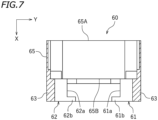
- FIG. 7 is a cross-sectional view of FIG. 6 taken along line VII-VII in FIG. 6 .
- the cover 60 is formed of a resin.
- the cover 60 includes a cover main body 65 fit to the connector 55, and a first electric wire guide 61 and a second electric wire guide 62 provided on the cover main body 65.
- the cover main body 65 is formed to be substantially box-like.
- the cover main body 65 has an opening 65A and an opening 65B formed therein.
- the connector 55 is inserted into the opening 65A, and the opening 65B is opened in the first direction X.
- the first electric wire guide 61 guides the first middle portion 41b of the first electric wire 41 such that the first middle portion 41b extends in the first direction X.
- the first electric wire guide 61 is configured to suppress movement of the first middle portion 41b of the first electric wire 41 in the second direction Y perpendicular to the first direction X.
- the first electric wire guide 61 is located further in the first direction X than the first insertion opening 56 of the connector 55.
- the first electric wire guide 61 extends in the first direction X from a perimeter of the opening 65B of the cover main body 65.
- the first electric wire guide 61 includes a semicylindrical guide main body 61a and a pair of bars 61b extending in the second direction Y from an end, in the first direction X, of the guide main body 61a.
- the pair of bars 61b are aligned in the third direction Z.
- the first middle portion 41b of the first electric wire 41 is supported by the guide main body 61a and the bars 61b to be guided in the first direction X.
- the second electric wire guide 62 guides the second middle portion 42b of the second electric wire 42 such that the second middle portion 42b extends in the first direction X.
- the second electric wire guide 62 is located further in the first direction X than the second insertion opening 57 of the connector 55.
- the second electric wire guide 62 has substantially the same structure as that of the first electric wire guide 61.
- the second electric wire guide 62 extends in the first direction X from the perimeter of the opening 65B of the cover main body 65.
- the second electric wire guide 62 includes a semicylindrical guide main body 62a and a pair of bars 62b extending in the second direction Y from an end, in the first direction X, of the guide main body 62a.
- the pair of bars 62b are aligned in the third direction Z.
- the second middle portion 42b of the second electric wire 42 is supported by the guide main body 62a and the bars 62b to be guided in the first direction X.
- the first electric wire guide 61 includes ribs 63.
- the ribs 63 are provided on the guide main body 61a of the first electric wire guide 61, and protrude outward in a diametric direction of the guide main body 61a.
- the first electric wire guide 61 includes three ribs 63.
- the second electric wire guide 62 also includes three ribs 63.
- the ribs 63 are provided on the guide main body 62a of the second electric wire guide 62, and protrude outward in a diametric direction of the guide main body 62a.
- the above-described structure of the cover 60 is merely an example. There is no specific limitation on the structure of the cover 60.
- the cover 60 is fit to the connector 55.
- the first electric wire 41 extends in the first direction X from the first insertion opening 56 (see FIG. 4 ) of the connector 55 through the cover 60.
- the second electric wire 42 extends in the first direction X from the second insertion opening 57 of the connector 55 through the cover 60.
- the third electric wire 43 extends in the first direction X from the third insertion opening 58 of the connector 55 through the cover 60.
- the first electric wire guide 61 and the first middle portion 41b of the first electric wire 41 are adjacent to each other in the second direction Y.
- the first middle portion 41b of the first electric wire 41 is inserted between the pair of bars 61b of the first electric wire guide 61.
- the first middle portion 41b of the first electric wire 41 is secured to the first electric wire guide 61 by a first band 71.
- the first band 71 is wound around the guide main body 61a of the first electric wire guide 61 and the first middle portion 41b of the first electric wire 41. This prevents the first middle portion 41b of the first electric wire 41 from being significantly bent.
- the first electric wire guide 61 prevents the first middle portion 41b of the first electric wire 41 from being significantly shifted from the first direction X.
- the second electric wire guide 62 and the second middle portion 42b of the second electric wire 42 are adjacent to each other in the second direction Y.
- the second middle portion 42b of the second electric wire 42 is inserted between the pair of bars 62b of the second electric wire guide 62.
- the second middle portion 42b of the second electric wire 42 is secured to the second electric wire guide 62 by a second band 72.
- the second band 72 is wound around the guide main body 62a of the second electric wire guide 62 and the second middle portion 42b of the second electric wire 42. This prevents the second middle portion 42b of the second electric wire 42 from being significantly bent.
- the second electric wire guide 62 prevents the second middle portion 42b of the second electric wire 42 from being significantly shifted from the first direction X.
- the first terminal 51 is put into contact with the terminal 51A of the wire harness 90
- the second terminal 52 is put into contact with the terminal 52A of the wire harness 90
- the third terminal 53 is put into contact with the terminal 53A of the wire harness 90.
- the motor 21 is connected with the controller 20 via the wire harness 30 and the wire harness 90. Electric power is supplied from the controller 20 to the motor 21 via the wire harness 90 and the wire harness 30.
- the first terminal 51 is a male terminal
- the terminal 51A (another terminal) is a female terminal.
- the first terminal 51 overlaps the terminal 51A, connected therewith via the connection opening 59 (see FIG. 8 ), in the direction perpendicular to the first direction X, and thus is electrically connected with the terminal 51A.
- the terminal 51A includes a folded leaf spring portion 51b. The leaf spring portion 51b exerts a spring force and presses the first terminal 51 in the direction perpendicular to the first direction.
- the first electric wire 41 of the wire harness 30 may possibly be sharply bent in the case where the power supply circuit 25 is located at a certain position. In the case where as shown in, for example, FIG. 9 , the first electric wire 41 is sharply bent, a restoring force F1 is generated in the first electric wire 41 to restore the electric wire 41 to be straight. If the cover 60 is not provided, the first terminal 51 receives a force F2 in the direction perpendicular to the first direction X from the first electric wire 41. As a result, the contact pressure received by the first terminal 51 from the terminal 51A of the wire harness 90 may possibly be increased or decreased locally. Particularly in the case where the wire harness 30 vibrates while the motorcycle 1 is running, the contact pressure on the first terminal 51 may possibly become excessive or insufficient.
- the cover 60 including the first electric wire guide 61 is attached to the connector 55.
- the first middle portion 41b of the first electric wire 41 is supported by the first electric wire guide 61 and guided to extend in the first direction X.
- the first electric wire guide 61 prevents or suppresses the bending of the first middle portion 41b. Therefore, even though the restoring force F1 is generated in the first electric wire 41, the force F2 received by the first terminal 51 from the first electric wire 41 becomes zero or is decreased. Therefore, the contact pressure on the first terminal 51 is kept favorable.
- the second electric wire guide 62 guides the second middle portion 42b of the second electric wire 42 such that the second middle portion 42b extends in the first direction X. Therefore, the contact pressure on the second terminal 52 is kept favorable.
- the first middle portion 41b, of the first electric wire 41, contiguous to the first tip portion 41a is guided by the first electric wire guide 61 to extend in the first direction X. Therefore, the first terminal 51 crimped to the first tip portion 41a is unlikely to receive a force in the direction perpendicular to the first direction X from the first electric wire 41. This allows the contact pressure received by the first terminal 51 from the terminal 51A of the wire harness 90 to be kept favorable.
- the second electric wire guide 62 guides the second middle portion 42b of the second electric wire 42.
- the wire harness 30 maintains a favorable connection with the another wire harness 90 even while the motorcycle 1 is running. According to the wire harness 30 in this embodiment, the bending of the first electric wire 41 and the second electric wire 42 in the vicinity of the connector 55 is tolerated. Therefore, there is little need to restrict the position where the wire harness 30 may be installed.
- the first middle portion 41b of the first electric wire 41 is secured to the first electric wire guide 61 by the first band 71.
- the first middle portion 41b is firmly secured to the first electric wire guide 61. Therefore, the fluctuation of the contact pressure on the first terminal 51 is further suppressed.
- the second middle portion 42b of the second electric wire 42 is secured to the second electric wire guide 62 by the second band 72.
- the second middle portion 42b is firmly secured to the second electric wire guide 62. Therefore, the fluctuation of the contact pressure on the second terminal 52 is further suppressed.
- the first electric wire guide 61 includes the guide main body 61a, and the guide main body 61a has an arc-shaped cross-section taken along the direction perpendicular to the first direction X.
- the guide main body 61a is formed to have a semicylindrical shape extending in the first direction X. Therefore, a contact area of the guide main body 61a with the first middle portion 41b of the first electric wire 41 is enlarged.
- the first electric wire guide 61 includes the guide main body 61a, and therefore, guides the first middle portion 41b of the first electric wire 41 favorably.
- the second electric wire guide 62 includes the guide main body 62a, and therefore, guides the second middle portion 42b of the second electric wire 42 favorably.
- the guide main body 61a of the first electric wire guide 61 and the guide main body 62a of the second electric wire guide 62 each have the ribs 63 provided thereon.
- the ribs 63 increase the rigidity of the first electric wire guide 61 and the second electric wire guide 62. Therefore, the first electric wire guide 61 guides the first middle portion 41b of the first electric wire 41 favorably, and the second electric wire guide 62 guides the second middle portion 42b of the second electric wire 42 favorably.
- size LY of the first terminal 51 in the second direction Y is shorter than size LZ of the first terminal 51 in the third direction Z.
- the contact pressure received by the first terminal 51 from the terminal 51A of the wire harness 90 becomes excessive or insufficient.
- the force in the second direction Y applied to the first middle portion 41b of the first electric wire 41 is received by the first electric wire guide 61. Therefore, the first terminal 51 is unlikely to receive the force in the second direction Y. This allows the contact pressure on the first terminal 51 to be kept favorable.
- the cover 60 including the first electric wire guide 61 and the second electric wire guide 62 may be integrated with the connector 55.
- the cover 60 is separate from the connector 55. Attaching the cover 60 to the connector 55 results in the first electric wire guide 61 and the second electric wire guide 62 being located at appropriate positions.
- the cover 60 is attached to the connector 55 but not to the connector 55A. Needless to say, substantially the same cover 60 may be attached to the connector 55A.
- the terminal 51A includes the leaf spring portion 51b providing the first terminal 51 with a pressing force in the direction perpendicular to the first direction X.
- the leaf spring portion 51b may be omitted.
- the first terminal 51 is a male terminal and the terminal 51A is a female terminal.
- the first terminal 51 of the wire harness 30 is not limited to a male terminal and may be a female terminal.
- the first terminal 51 may be a female terminal and the terminal 51A may be a male terminal.
- the first terminal 51 may include the leaf spring portion 51b providing the terminal 51A with a pressing force in the direction perpendicular to the first direction X.
- the first terminal 51 and the terminal 51A do not need to be shaped to be fit to each other.
- the first terminal 51 and the terminal 51A may each have any other shape that allows the first terminal 51 and the terminal 51A to be electrically connected with each other when overlapping each other in the direction perpendicular to the first direction X.
- the wire harness 30 is included in the power supply circuit 25. There is no specific limitation on the position where the wire harness 30 is installed.
- the wire harness 30 may be included in, for example, an electric circuit connecting the controller and a driving source for running to each other, an electric circuit connecting the controller and an actuator to each other, or an electric circuit connecting the controller and a sensor to each other.
- the first middle portion 41b of the first electric wire 41 and the first electric wire guide 61 are secured to each other by the first band 71.
- the member securing the first middle portion 41b and the first electric wire guide 61 to each other is not limited to the first band 71.
- the second middle portion 42b of the second electric wire 42 and the second electric wire guide 62 are secured to each other by the second band 72.
- the member securing the second middle portion 42b and the second electric wire guide 62 to each other is not limited to the second band 72.
- the number of the ribs 63 of each of the first electric wire guide 61 and the second electric wire guide 62 is not limited to three.
- the rib(s) 63 may be provided in the number of one, two, or four or more. There is no absolute need of the rib(s) 63, and the rib(s) 63 may be omitted.
- the direction in which the first electric wire guide 61 and the first middle portion 41b of the first electric wire 41 are adjacent to each other merely needs to be perpendicular to the first direction X, and is not limited to the second direction Y.
- the direction in which the second electric wire guide 62 and the second middle portion 42b of the second electric wire 42 are adjacent to each other merely needs to be perpendicular to the first direction X, and is not limited to the second direction Y.
- the cover 60 may include another electric wire guide that guides the third middle portion 43b of the third electric wire 43 such that the third middle portion 43b extends in the first direction X.
- the cover 60 does not need to include both of the first electric wire guide 61 and the second electric wire guide 62.
- the cover 60 may include either the first electric wire guide 61 or the second electric wire guide 62 in accordance with the position where the wire harness 30 is installed.
- the wire harness includes various types of electric wires connecting electric components.
- the wire harness includes a so-called sub lead.
- the straddled vehicle is a vehicle on which a rider rides while straddling.
- the straddled vehicle is not limited to a motorcycle 1.
- the straddled vehicle may be, for example, a three-wheeled motorized vehicle, an ATV (All Terrain vehicle), or a snowmobile.
- the wire harness 30 may be included in a straddled vehicle other than the motorcycle 1. Alternatively, the wire harness 30 may be included in a vehicle other than the straddled vehicle.
- the present invention encompasses any of preferred embodiments including equivalent elements, modifications, deletions, combinations, improvements and/or alterations which can be recognized by a person of ordinary skill in the art based on the disclosure.
- the elements of each claim should be interpreted broadly based on the terms used in the claim, and should not be limited to any of the preferred embodiments described in this specification or used during the prosecution of the present application.
Landscapes
- Engineering & Computer Science (AREA)
- Mechanical Engineering (AREA)
- Details Of Connecting Devices For Male And Female Coupling (AREA)
- Connections Effected By Soldering, Adhesion, Or Permanent Deformation (AREA)
Abstract
There is disclosed a vehicle wire harness (30) including a first terminal (51); a first electric wire (41) including a first tip portion (41a) having the first terminal (51) crimped thereto and a first middle portion (41b) contiguous to the first tip portion (41a); a connector (55) having a first insertion opening (56) opened in a first direction (X) formed therein, and having the first terminal (51) inserted thereto; and a first electric wire guide (61) located further in the first direction (X) than the first insertion opening (56) of the connector (55), the first electric wire guide (61) guiding the first middle portion (41b) of the first electric wire (41) such that the first middle portion (41b) extends in the first direction (X).
Description
- The present invention relates to a vehicle wire harness and a straddled vehicle including the same.
- Conventionally, a wire harness is used in a vehicle such as a straddled vehicle or the like (see, for example, Patent Literature 1 (
JP2022-72967A - Patent Literature 1:
JP2022-72967A - As schematically shown in
FIG. 11 , there may be a case where anelectric wire 101 is sharply bent in the vicinity of aconnector 103 in the case where the wire harness is installed at a certain position. In this case, a restoring force Fa against the bending is generated in theelectric wire 101. Therefore, aterminal 102 crimped to a tip portion of theelectric wire 101 receives a force Fb from theelectric wire 101. In the case where the wire harness is connected with another wire harness, theterminal 102 is in contact with aterminal 102B of the another wire harness. A contact pressure is generated between theterminal 102 and theterminal 102B. Particularly in the case where theterminal 102B includes a folded portion (hereinafter, referred to as a "leaf spring portion") 102b, theleaf spring portion 102b exerts a spring force, and therefore, presses theterminal 102 strongly. When theterminal 102 receives the force Fb from theelectric wire 101, the contact pressure received by theterminal 102 from theterminal 102B increases or decreases locally. As can be seen, when theelectric wire 101 is sharply bent in the vicinity of theconnector 103, the contact pressure on theterminal 102 may possibly increase or decrease. - The vehicle wire harness vibrates while the vehicle is running. There is a case where the contact pressure on the
terminal 102 increases or decreases while the vehicle is running even though the pressure is favorable while the vehicle is at a stop. In order to connect theterminal 102 and theterminal 102B to each other favorably, it is preferred that the contact pressure on theterminal 102 is kept favorable even while the vehicle is running. - It is conceivable that a restriction is imposed on the position at which the wire harness may be installed such that the
electric wire 101 is not bent in the vicinity of theconnector 103. However, such a restriction imposed on the position of the wire harness results in poor convenience. - The present invention made in light of such a point has an object of providing a vehicle wire harness that hardly needs to be restricted regarding the position thereof and is capable of maintaining a favorable connection with another wire harness even while the vehicle is running, and a straddled vehicle including such a vehicle wire harness.
- The vehicle wire harness disclosed herein includes a first terminal; a first electric wire including a first tip portion having the first terminal crimped thereto and a first middle portion contiguous to the first tip portion; a connector having a first insertion opening opened in a first direction formed therein, and having the first terminal inserted thereto; and a first electric wire guide located further in the first direction than the first insertion opening of the connector, the first electric wire guide guiding the first middle portion of the first electric wire such that the first middle portion extends in the first direction.
- According to the above-described vehicle wire harness, even if the first electric wire is sharply bent in the vicinity of the connector, the first middle portion contiguous to the first tip portion is guided by the first electric wire guide to extend in the first direction. Therefore, the first terminal crimped to the first tip portion is unlikely to receive a force in a direction perpendicular to the first direction from the first electric wire. As a result, a contact pressure received by the first terminal from another terminal while the first termina is connected with the another terminal (hereinafter, such a pressure will be referred to as a "contact pressure on the first terminal") is kept favorable. The above-described vehicle wire harness maintains a favorable connection with another wire harness including the another terminal even while the vehicle is running. In addition, the above-described wire harness tolerates the bending of the first electric wire in the vicinity of the connector. Therefore, there is little need to restrict the position where the wire harness may be installed.
- The connector may have a connection opening, opened in a direction opposite to the first direction, formed therein. The first terminal may be configured to overlap another terminal connected thereto via the connection opening, the first terminal overlapping the another terminal in a second direction perpendicular to the first direction.
- With such a structure, the first terminal of the vehicle wire harness and the another terminal of the another vehicle wire harness overlap in the direction perpendicular to the first direction, and thus are electrically connected with each other. As described above, the first terminal is unlikely to receive a force in the direction perpendicular to the first direction from the first electric wire. This allows the contact pressure on the first terminal to be kept favorable.
- The first electric wire guide may be configured to suppress movement of the first middle portion of the first electric wire in the second direction.
- The connector may have a connection opening, opened in a direction opposite to the first direction, formed therein. The first terminal may include a leaf spring portion providing another terminal, connected thereto via the connection opening, with a pressing force in a direction perpendicular to the first direction.
- The vehicle wire harness may further include a first band securing the first middle portion of the first electric wire to the first electric wire guide.
- With such a structure, the first middle portion of the first electric wire is firmly secured to the first electric wire guide. This allows the contact pressure on the first terminal to be kept favorable.
- The first electric wire guide may include a portion having an arc-shaped cross-section taken along a direction perpendicular to the first direction. The first electric wire guide may include a semicylindrical portion extending in the first direction.
- With such a structure, the first electric wire guide guides the first middle portion of the first electric wire favorably.
- The first electric wire guide may include a guide main body supporting the first middle portion of the first electric wire, and one or a plurality of ribs provided on the guide main body and extending in the first direction.
- With such a structure, the rigidity of the first electric wire guide is increased. The first electric wire guide guides the first middle portion of the first electric wire favorably.
- The size of the first terminal in a second direction perpendicular to the first direction may be shorter than the size of the first terminal in a third direction perpendicular to the first direction and the second direction. The first electric wire guide and the first middle portion of the first electric wire may be adjacent to each other in the second direction.
- In the case where the size of a terminal in the second direction is shorter than the size of the terminal in the third direction, there is a tendency that when such a terminal receives a force in the second direction, the contact pressure on the terminal applied from another terminal is increased or decreased. However, in the above-described vehicle wire harness, the first electric wire guide and the first middle portion of the first electric wire are adjacent to each other in the second direction. Therefore, the force applied to the first middle portion in the second direction is received by the first electric wire guide. Thus, the first terminal is unlikely to receive the force in the second direction. This allows the contact pressure on the first terminal to be kept favorable.
- The connector may have a second insertion opening opened in the first direction formed therein. The vehicle wire harness may further include a second terminal inserted into the second insertion opening, a second electric wire including a second tip portion having the second terminal crimped thereto and a second middle portion contiguous to the second tip portion), and a second electric wire guide located further in the first direction than the second insertion opening of the connector, the second electric wire guide guiding the second middle portion of the second electric wire such that the second middle portion extends in the first direction. The first electric wire guide and the first middle portion of the first electric wire may be adjacent to each other in a second direction perpendicular to the first direction. The second electric wire guide and the second middle portion of the second electric wire may be adjacent to each other in the second direction.
- With such a structure, in the vehicle wire harness in which the first terminal and the second terminal are inserted into a single connector, the contact pressure on the first terminal and a contact pressure on the second terminal are kept favorable. Regarding the vehicle wire harness including the first electric wire and the second electric wire, the restriction on the position where the vehicle wire harness may be installed is alleviated, and a favorable connection with another vehicle wire harness while the vehicle is running is realized.
- The vehicle wire harness may include a cover including the first electric wire guide, the cover being separate from the connector. The cover may be attached to the connector.
- With such a structure, attaching the cover to the connector results in the first electric wire guide being located at an appropriate position.
- The vehicle wire harness may include a cover including the first electric wire guide and the second electric wire guide, the cover being separate from the connector. The cover may be attached to the connector.
- With such a structure, attaching the cover to the connector results in the first electric wire guide and the second electric wire guide being located at appropriate positions.
- The first electric wire may have an outer diameter of 3 to 6 mm.
- The straddled vehicle disclosed herein includes the above-described vehicle wire harness.
- The straddled vehicle may include the above-described vehicle wire harness; and another vehicle wire harness including another terminal, another electric wire having the another terminal crimped thereto, and another connector having the another terminal inserted thereto. The connector may have a connection opening, opened in a direction opposite to the first direction, formed therein. The another terminal may be connected with the first terminal via the connection opening by the connector and the another connector being connected with each other. The first terminal and the another terminal may overlap each other in a second direction perpendicular to the first direction.
- The first electric wire guide may be configured to suppress movement of the first middle portion of the first electric wire in the second direction.
- The straddled vehicle may further include a controller, a motor, and a power supply circuit connecting the controller and the motor to each other. The vehicle wire harness may be included in the power supply circuit.
- The straddled vehicle may be a motorcycle.
- The present invention provides a vehicle wire harness that hardly needs to be restricted regarding the position thereof and is capable of maintaining a favorable connection with another wire harness even while the vehicle is running, and a straddled vehicle including such a vehicle wire harness.
-
-
FIG. 1 is a side view of a motorcycle according to an embodiment of the present invention. -
FIG. 2 is a circuit configuration of a power supply circuit included in the motorcycle. -
FIG. 3 is a perspective view of a first electric wire and a first terminal. -
FIG. 4 is a perspective view of a connector. -
FIG. 5 is a perspective view of a cover. -
FIG. 6 is a plan view of the cover. -
FIG. 7 is a cross-sectional view ofFIG. 6 taken along line VII-VII inFIG. 6 . -
FIG. 8 is a perspective view of a part of a wire harness. -
FIG. 9 is a cross-sectional view showing a part of a wire harness including no cover. -
FIG. 10 is a cross-sectional view showing a part of the wire harness according to the embodiment. -
FIG. 11 is a cross-sectional view showing a part of a conventional wire harness. - Hereinafter, an embodiment of a vehicle wire harness and a straddled vehicle including the same will be described with reference to the drawings.
-
FIG. 1 is a side view of amotorcycle 1 as an example of a straddled vehicle. Themotorcycle 1 includes avehicle frame 5, aseat 9 on which a rider sits, afront wheel 6, arear wheel 7, aninternal combustion engine 8 as an example of a driving source for running, and ahandle 11. Thevehicle frame 5 includes ahead pipe 3, and amain frame 4 extending rearward from thehead pipe 3. A steeringshaft 10 is supported by thehead pipe 3 so as to be rotatable leftward and rightward. Thehandle 11 is connected with the steeringshaft 10. - As shown in
FIG. 2 , themotorcycle 1 includes acontroller 20 connected with a battery (not shown), amotor 21, and apower supply circuit 25 connecting thecontroller 20 and themotor 21 to each other. Thepower supply circuit 25 supplies electric power from thecontroller 20 to themotor 21. - The
power supply circuit 25 includes awire harness 90 and awire harness 30 connected with thewire harness 90. Thewire harness 90 is directly or indirectly connected with thecontroller 20. Thewire harness 30 is directly or indirectly connected with themotor 21. - The
wire harness 90 includes anelectric wire 41A, anelectric wire 42A, anelectric wire 43A, a terminal 51A crimped to theelectric wire 41A, a terminal 52A crimped to theelectric wire 42A, a terminal 53A crimped to theelectric wire 43A, and aconnector 55A having theterminals 51A through 53A inserted thereto. - Now, the
wire harness 30 will be described in detail. Thewire harness 30 includes a firstelectric wire 41, a secondelectric wire 42 and a thirdelectric wire 43. Thewire harness 30 includes afirst terminal 51 crimped to the firstelectric wire 41, asecond terminal 52 crimped to the secondelectric wire 42, and a third terminal 53 crimped to the thirdelectric wire 43. Thewire harness 30 includes aconnector 55 having thefirst terminal 51, thesecond terminal 52 and the third terminal 53 inserted thereto, and acover 60 attached to theconnector 55. -
FIG. 3 is a perspective view of the firstelectric wire 41 and thefirst terminal 51. The firstelectric wire 41 includes a plurality ofcore wires 45 formed of a conductive material such as a metal material or the like, and acylindrical covering member 46 surrounding thecore wires 45. The coveringmember 46 is formed of an insulating material such as a resin or the like. The secondelectric wire 42 and the thirdelectric wire 43 each have substantially the same structure as that of the firstelectric wire 41. It should be noted that there is no specific limitation on the structure of the firstelectric wire 41, the secondelectric wire 42 or the thirdelectric wire 43. There is no specific limitation on the size of the firstelectric wire 41, the secondelectric wire 42 or the thirdelectric wire 43, either. Herein, the firstelectric wire 41, the secondelectric wire 42 and the thirdelectric wire 43 each have an outer diameter D40 of 3 to 6 mm. - The first
electric wire 41 includes afirst tip portion 41a having thefirst terminal 51 crimped thereto, and a firstmiddle portion 41b contiguous to thefirst tip portion 41a. The secondelectric wire 42 includes asecond tip portion 42a having thesecond terminal 52 crimped thereto, and a secondmiddle portion 42b contiguous to thesecond tip portion 42a. The thirdelectric wire 43 includes athird tip portion 43a having the third terminal 53 crimped thereto, and a thirdmiddle portion 43b contiguous to thethird tip portion 43a. The firstmiddle portion 41b, the secondmiddle portion 42b and the thirdmiddle portion 43b each have a length of, for example, 3 cm. - The
first terminal 51 and the firstmiddle portion 41b of the firstelectric wire 41 are aligned in a first direction X. Thesecond terminal 52 and the secondmiddle portion 42b of the secondelectric wire 42 are also aligned in the first direction X. Thethird terminal 53 and the thirdmiddle portion 43b of the thirdelectric wire 43 are also aligned in the first direction X. As shown inFIG. 2 , the firstmiddle portion 41b of the firstelectric wire 41, the secondmiddle portion 42b of the secondelectric wire 42, and the thirdmiddle portion 43b of the thirdelectric wire 43 are aligned in a second direction Y perpendicular to the first direction X. The thirdmiddle portion 43b of the thirdelectric wire 43 is located between the firstmiddle portion 41b of the firstelectric wire 41 and the secondmiddle portion 42b of the secondelectric wire 42. - The
first terminal 51, thesecond terminal 52 and thethird terminal 53 are formed of a conductive material such as a metal material or the like. Thefirst terminal 51, thesecond terminal 52 and thethird terminal 53 are aligned in the second direction Y. Thethird terminal 53 is located between thefirst terminal 51 and thesecond terminal 52. As shown inFIG. 3 , a direction perpendicular to the first direction X and the second direction Y will be referred to as a third direction Z. Size LY of thefirst terminal 51 in the second direction Y is shorter than size LZ of thefirst terminal 51 in the third direction Z. Thefirst terminal 51 is formed to be like a thin plate. Thesecond terminal 52 and thethird terminal 53 each have substantially the same structure as that of thefirst terminal 51. It should be noted that there is no specific limitation on the structure of thefirst terminal 51, thesecond terminal 52 or thethird terminal 53. -
FIG. 4 is a perspective view of theconnector 55. Theconnector 55 is formed of an insulating material such as a resin or the like. Theconnector 55 has afirst insertion opening 56, asecond insertion opening 57 and a third insertion opening 58 formed therein, and thefirst insertion opening 56, thesecond insertion opening 57 and thethird insertion opening 58 are each opened in the first direction X. Thefirst insertion opening 56, thesecond insertion opening 57 and thethird insertion opening 58 are aligned in the second direction Y. Thethird insertion opening 58 is located between thefirst insertion opening 56 and thesecond insertion opening 57. Thefirst terminal 51 is inserted into thefirst insertion opening 56, thesecond terminal 52 is inserted into the second insertion opening 57, and thethird terminal 53 is inserted into thethird insertion opening 58. Theconnector 55 has aconnection opening 59 formed therein, and theconnection opening 59 is opened in an opposite direction XB opposite to the first direction X. Theconnector 55A of the wire harness 90 (seeFIG. 2 ) is connected with theconnection opening 59. -
FIG. 5 is a perspective view of thecover 60.FIG. 6 is a plan view of thecover 60, and is a view of thecover 60 as seen in the direction opposite to the first direction X.FIG. 7 is a cross-sectional view ofFIG. 6 taken along line VII-VII inFIG. 6 . There is no specific limitation on the material of thecover 60. In this embodiment, thecover 60 is formed of a resin. Thecover 60 includes a covermain body 65 fit to theconnector 55, and a firstelectric wire guide 61 and a secondelectric wire guide 62 provided on the covermain body 65. - There is no specific limitation on the shape of the cover
main body 65. In this embodiment, the covermain body 65 is formed to be substantially box-like. The covermain body 65 has anopening 65A and anopening 65B formed therein. Theconnector 55 is inserted into theopening 65A, and theopening 65B is opened in the first direction X. - The first
electric wire guide 61 guides the firstmiddle portion 41b of the firstelectric wire 41 such that the firstmiddle portion 41b extends in the first direction X. The firstelectric wire guide 61 is configured to suppress movement of the firstmiddle portion 41b of the firstelectric wire 41 in the second direction Y perpendicular to the first direction X. The firstelectric wire guide 61 is located further in the first direction X than thefirst insertion opening 56 of theconnector 55. The firstelectric wire guide 61 extends in the first direction X from a perimeter of theopening 65B of the covermain body 65. The firstelectric wire guide 61 includes a semicylindrical guidemain body 61a and a pair ofbars 61b extending in the second direction Y from an end, in the first direction X, of the guidemain body 61a. The pair ofbars 61b are aligned in the third direction Z. As shown inFIG. 8 , the firstmiddle portion 41b of the firstelectric wire 41 is supported by the guidemain body 61a and thebars 61b to be guided in the first direction X. - The second
electric wire guide 62 guides the secondmiddle portion 42b of the secondelectric wire 42 such that the secondmiddle portion 42b extends in the first direction X. The secondelectric wire guide 62 is located further in the first direction X than the second insertion opening 57 of theconnector 55. The secondelectric wire guide 62 has substantially the same structure as that of the firstelectric wire guide 61. In more detail, the secondelectric wire guide 62 extends in the first direction X from the perimeter of theopening 65B of the covermain body 65. The secondelectric wire guide 62 includes a semicylindrical guidemain body 62a and a pair ofbars 62b extending in the second direction Y from an end, in the first direction X, of the guidemain body 62a. The pair ofbars 62b are aligned in the third direction Z. As shown inFIG. 8 , the secondmiddle portion 42b of the secondelectric wire 42 is supported by the guidemain body 62a and thebars 62b to be guided in the first direction X. - As shown in
FIG. 5 , the firstelectric wire guide 61 includesribs 63. Theribs 63 are provided on the guidemain body 61a of the firstelectric wire guide 61, and protrude outward in a diametric direction of the guidemain body 61a. There is no specific limitation on the number of theribs 63. Herein, the firstelectric wire guide 61 includes threeribs 63. The secondelectric wire guide 62 also includes threeribs 63. Theribs 63 are provided on the guidemain body 62a of the secondelectric wire guide 62, and protrude outward in a diametric direction of the guidemain body 62a. - The above-described structure of the
cover 60 is merely an example. There is no specific limitation on the structure of thecover 60. - As described above, the
cover 60 is fit to theconnector 55. As shown inFIG. 8 , the firstelectric wire 41 extends in the first direction X from the first insertion opening 56 (seeFIG. 4 ) of theconnector 55 through thecover 60. The secondelectric wire 42 extends in the first direction X from the second insertion opening 57 of theconnector 55 through thecover 60. The thirdelectric wire 43 extends in the first direction X from the third insertion opening 58 of theconnector 55 through thecover 60. - The first
electric wire guide 61 and the firstmiddle portion 41b of the firstelectric wire 41 are adjacent to each other in the second direction Y. The firstmiddle portion 41b of the firstelectric wire 41 is inserted between the pair ofbars 61b of the firstelectric wire guide 61. The firstmiddle portion 41b of the firstelectric wire 41 is secured to the firstelectric wire guide 61 by afirst band 71. In more detail, thefirst band 71 is wound around the guidemain body 61a of the firstelectric wire guide 61 and the firstmiddle portion 41b of the firstelectric wire 41. This prevents the firstmiddle portion 41b of the firstelectric wire 41 from being significantly bent. The firstelectric wire guide 61 prevents the firstmiddle portion 41b of the firstelectric wire 41 from being significantly shifted from the first direction X. - Similarly, the second
electric wire guide 62 and the secondmiddle portion 42b of the secondelectric wire 42 are adjacent to each other in the second direction Y. The secondmiddle portion 42b of the secondelectric wire 42 is inserted between the pair ofbars 62b of the secondelectric wire guide 62. The secondmiddle portion 42b of the secondelectric wire 42 is secured to the secondelectric wire guide 62 by asecond band 72. In more detail, thesecond band 72 is wound around the guidemain body 62a of the secondelectric wire guide 62 and the secondmiddle portion 42b of the secondelectric wire 42. This prevents the secondmiddle portion 42b of the secondelectric wire 42 from being significantly bent. The secondelectric wire guide 62 prevents the secondmiddle portion 42b of the secondelectric wire 42 from being significantly shifted from the first direction X. - As shown in
FIG. 2 , when theconnector 55 and theconnector 55A are connected with each other, thefirst terminal 51 is put into contact with the terminal 51A of thewire harness 90, thesecond terminal 52 is put into contact with the terminal 52A of thewire harness 90, and thethird terminal 53 is put into contact with the terminal 53A of thewire harness 90. As a result, thewire harness 30 and thewire harness 90 are connected with each other. Themotor 21 is connected with thecontroller 20 via thewire harness 30 and thewire harness 90. Electric power is supplied from thecontroller 20 to themotor 21 via thewire harness 90 and thewire harness 30. - In this embodiment, the
first terminal 51 is a male terminal, and theterminal 51A (another terminal) is a female terminal. As shown inFIG. 9 , thefirst terminal 51 overlaps the terminal 51A, connected therewith via the connection opening 59 (seeFIG. 8 ), in the direction perpendicular to the first direction X, and thus is electrically connected with the terminal 51A. In this embodiment, theterminal 51A includes a foldedleaf spring portion 51b. Theleaf spring portion 51b exerts a spring force and presses thefirst terminal 51 in the direction perpendicular to the first direction. - The first
electric wire 41 of thewire harness 30 may possibly be sharply bent in the case where thepower supply circuit 25 is located at a certain position. In the case where as shown in, for example,FIG. 9 , the firstelectric wire 41 is sharply bent, a restoring force F1 is generated in the firstelectric wire 41 to restore theelectric wire 41 to be straight. If thecover 60 is not provided, thefirst terminal 51 receives a force F2 in the direction perpendicular to the first direction X from the firstelectric wire 41. As a result, the contact pressure received by the first terminal 51 from the terminal 51A of thewire harness 90 may possibly be increased or decreased locally. Particularly in the case where thewire harness 30 vibrates while themotorcycle 1 is running, the contact pressure on thefirst terminal 51 may possibly become excessive or insufficient. - However, according to this embodiment, the
cover 60 including the firstelectric wire guide 61 is attached to theconnector 55. As shown inFIG. 10 , the firstmiddle portion 41b of the firstelectric wire 41 is supported by the firstelectric wire guide 61 and guided to extend in the first direction X. The firstelectric wire guide 61 prevents or suppresses the bending of the firstmiddle portion 41b. Therefore, even though the restoring force F1 is generated in the firstelectric wire 41, the force F2 received by the first terminal 51 from the firstelectric wire 41 becomes zero or is decreased. Therefore, the contact pressure on thefirst terminal 51 is kept favorable. - The same is applicable to the second
electric wire 42 and thesecond terminal 52 although a detailed description thereof will be omitted. The secondelectric wire guide 62 guides the secondmiddle portion 42b of the secondelectric wire 42 such that the secondmiddle portion 42b extends in the first direction X. Therefore, the contact pressure on thesecond terminal 52 is kept favorable. - As described above, according to the
wire harness 30 in this embodiment, even if the firstelectric wire 41 is sharply bent in the vicinity of theconnector 55, the firstmiddle portion 41b, of the firstelectric wire 41, contiguous to thefirst tip portion 41a is guided by the firstelectric wire guide 61 to extend in the first direction X. Therefore, thefirst terminal 51 crimped to thefirst tip portion 41a is unlikely to receive a force in the direction perpendicular to the first direction X from the firstelectric wire 41. This allows the contact pressure received by the first terminal 51 from the terminal 51A of thewire harness 90 to be kept favorable. Similarly, the secondelectric wire guide 62 guides the secondmiddle portion 42b of the secondelectric wire 42. This allows the contact pressure received by the second terminal 52 from the terminal 52A of thewire harness 90 to be kept favorable. Therefore, thewire harness 30 maintains a favorable connection with the anotherwire harness 90 even while themotorcycle 1 is running. According to thewire harness 30 in this embodiment, the bending of the firstelectric wire 41 and the secondelectric wire 42 in the vicinity of theconnector 55 is tolerated. Therefore, there is little need to restrict the position where thewire harness 30 may be installed. - According to this embodiment, the first
middle portion 41b of the firstelectric wire 41 is secured to the firstelectric wire guide 61 by thefirst band 71. The firstmiddle portion 41b is firmly secured to the firstelectric wire guide 61. Therefore, the fluctuation of the contact pressure on thefirst terminal 51 is further suppressed. The secondmiddle portion 42b of the secondelectric wire 42 is secured to the secondelectric wire guide 62 by thesecond band 72. The secondmiddle portion 42b is firmly secured to the secondelectric wire guide 62. Therefore, the fluctuation of the contact pressure on thesecond terminal 52 is further suppressed. - According to this embodiment, the first
electric wire guide 61 includes the guidemain body 61a, and the guidemain body 61a has an arc-shaped cross-section taken along the direction perpendicular to the first direction X. The guidemain body 61a is formed to have a semicylindrical shape extending in the first direction X. Therefore, a contact area of the guidemain body 61a with the firstmiddle portion 41b of the firstelectric wire 41 is enlarged. The firstelectric wire guide 61 includes the guidemain body 61a, and therefore, guides the firstmiddle portion 41b of the firstelectric wire 41 favorably. Similarly, the secondelectric wire guide 62 includes the guidemain body 62a, and therefore, guides the secondmiddle portion 42b of the secondelectric wire 42 favorably. - According to this embodiment, the guide
main body 61a of the firstelectric wire guide 61 and the guidemain body 62a of the secondelectric wire guide 62 each have theribs 63 provided thereon. Theribs 63 increase the rigidity of the firstelectric wire guide 61 and the secondelectric wire guide 62. Therefore, the firstelectric wire guide 61 guides the firstmiddle portion 41b of the firstelectric wire 41 favorably, and the secondelectric wire guide 62 guides the secondmiddle portion 42b of the secondelectric wire 42 favorably. - As shown in
FIG. 3 , size LY of thefirst terminal 51 in the second direction Y is shorter than size LZ of thefirst terminal 51 in the third direction Z. There is a tendency that when thefirst terminal 51 receives a force in the second direction Y, the contact pressure received by the first terminal 51 from the terminal 51A of thewire harness 90 becomes excessive or insufficient. However, according to this embodiment, the force in the second direction Y applied to the firstmiddle portion 41b of the firstelectric wire 41 is received by the firstelectric wire guide 61. Therefore, thefirst terminal 51 is unlikely to receive the force in the second direction Y. This allows the contact pressure on thefirst terminal 51 to be kept favorable. - The
cover 60 including the firstelectric wire guide 61 and the secondelectric wire guide 62 may be integrated with theconnector 55. In this embodiment, thecover 60 is separate from theconnector 55. Attaching thecover 60 to theconnector 55 results in the firstelectric wire guide 61 and the secondelectric wire guide 62 being located at appropriate positions. - One embodiment of the vehicle wire harness and the straddled vehicle including the same has been described. The above-described embodiment is merely an example, and various other embodiments may be carried out.
- In the above-described embodiment, the
cover 60 is attached to theconnector 55 but not to theconnector 55A. Needless to say, substantially thesame cover 60 may be attached to theconnector 55A. - In the above-described embodiment, the
terminal 51A includes theleaf spring portion 51b providing thefirst terminal 51 with a pressing force in the direction perpendicular to the first direction X. Theleaf spring portion 51b may be omitted. - In the above-described embodiment, the
first terminal 51 is a male terminal and the terminal 51A is a female terminal. Thefirst terminal 51 of thewire harness 30 is not limited to a male terminal and may be a female terminal. Thefirst terminal 51 may be a female terminal and the terminal 51A may be a male terminal. Thefirst terminal 51 may include theleaf spring portion 51b providing the terminal 51A with a pressing force in the direction perpendicular to the first direction X. Thefirst terminal 51 and the terminal 51A do not need to be shaped to be fit to each other. Thefirst terminal 51 and the terminal 51A may each have any other shape that allows thefirst terminal 51 and the terminal 51A to be electrically connected with each other when overlapping each other in the direction perpendicular to the first direction X. - In the above-described embodiment, the
wire harness 30 is included in thepower supply circuit 25. There is no specific limitation on the position where thewire harness 30 is installed. Thewire harness 30 may be included in, for example, an electric circuit connecting the controller and a driving source for running to each other, an electric circuit connecting the controller and an actuator to each other, or an electric circuit connecting the controller and a sensor to each other. - In the above-described embodiment, the first
middle portion 41b of the firstelectric wire 41 and the firstelectric wire guide 61 are secured to each other by thefirst band 71. The member securing the firstmiddle portion 41b and the firstelectric wire guide 61 to each other is not limited to thefirst band 71. The secondmiddle portion 42b of the secondelectric wire 42 and the secondelectric wire guide 62 are secured to each other by thesecond band 72. The member securing the secondmiddle portion 42b and the secondelectric wire guide 62 to each other is not limited to thesecond band 72. There is no absolute need of a member securing the firstmiddle portion 41b and the firstelectric wire guide 61 to each other, and such a member may be omitted as long as the firstelectric wire guide 61 guides the firstmiddle portion 41b. Similarly, there is no absolute need of a member securing the secondmiddle portion 42b and the secondelectric wire guide 62 to each other, and such a member may be omitted as long as the secondelectric wire guide 62 guides the secondmiddle portion 42b. - There is no specific limitation on the shape or the size of the
ribs 63 of the firstelectric wire guide 61 and the secondelectric wire guide 62. The number of theribs 63 of each of the firstelectric wire guide 61 and the secondelectric wire guide 62 is not limited to three. The rib(s) 63 may be provided in the number of one, two, or four or more. There is no absolute need of the rib(s) 63, and the rib(s) 63 may be omitted. - The direction in which the first
electric wire guide 61 and the firstmiddle portion 41b of the firstelectric wire 41 are adjacent to each other merely needs to be perpendicular to the first direction X, and is not limited to the second direction Y. The direction in which the secondelectric wire guide 62 and the secondmiddle portion 42b of the secondelectric wire 42 are adjacent to each other merely needs to be perpendicular to the first direction X, and is not limited to the second direction Y. - The
cover 60 may include another electric wire guide that guides the thirdmiddle portion 43b of the thirdelectric wire 43 such that the thirdmiddle portion 43b extends in the first direction X. Thecover 60 does not need to include both of the firstelectric wire guide 61 and the secondelectric wire guide 62. Thecover 60 may include either the firstelectric wire guide 61 or the secondelectric wire guide 62 in accordance with the position where thewire harness 30 is installed. - The wire harness includes various types of electric wires connecting electric components. The wire harness includes a so-called sub lead.
- The straddled vehicle is a vehicle on which a rider rides while straddling. The straddled vehicle is not limited to a
motorcycle 1. The straddled vehicle may be, for example, a three-wheeled motorized vehicle, an ATV (All Terrain vehicle), or a snowmobile. Thewire harness 30 may be included in a straddled vehicle other than themotorcycle 1. Alternatively, thewire harness 30 may be included in a vehicle other than the straddled vehicle. - The terms and expressions used herein are for description only and are not to be interpreted in a limited sense. These terms and expressions should be recognized as not excluding any equivalents to the elements shown and described herein and as allowing any modification encompassed in the scope of the claims. The present invention may be embodied in many various forms. This disclosure should be regarded as providing preferred embodiments of the principle of the present invention. These preferred embodiments are provided with the understanding that they are not intended to limit the present invention to the preferred embodiments described in the specification and/or shown in the drawings. The present invention is not limited to the preferred embodiment described herein. The present invention encompasses any of preferred embodiments including equivalent elements, modifications, deletions, combinations, improvements and/or alterations which can be recognized by a person of ordinary skill in the art based on the disclosure. The elements of each claim should be interpreted broadly based on the terms used in the claim, and should not be limited to any of the preferred embodiments described in this specification or used during the prosecution of the present application.
- 1 ... motorcycle (straddled vehicle); 20 ... controller; 21 ... motor; 25 ... power supply circuit; 30 ... wire harness (vehicle wire harness); 41 ... first electric wire; 41a ... first tip portion; 41b ... first middle portion; 42 ... second electric wire; 42a ... second tip portion; 42b ... second middle portion; 51 ... first terminal; 52 ... second terminal; 55 ... connector; 56 ... first insertion opening; 57 ... second insertion opening; 60 ... cover; 61 ... first electric wire guide; 61a ... guide main body; 62 ... second electric wire guide; 63 ... rib; 71 ... first band; X ... first direction; Y ... second direction; Z ... third direction
Claims (15)
- A vehicle wire harness (30), comprising:a first terminal (51);a first electric wire (41) including a first tip portion (41a) having the first terminal (51) crimped thereto and a first middle portion (41b) contiguous to the first tip portion (41a) ;a connector (55) having a first insertion opening (56) opened in a first direction (X) formed therein, and having the first terminal (51) inserted thereto; anda first electric wire guide (61) located further in the first direction (X) than the first insertion opening (56) of the connector (55), the first electric wire guide (61) guiding the first middle portion (41b) of the first electric wire (41) such that the first middle portion (41b) extends in the first direction (X).
- The vehicle wire harness (30) according to claim 1, wherein:the connector (55) has a connection opening (59), opened in an opposite direction (XB) opposite to the first direction (X), formed therein, andthe first terminal (51) is configured to overlap another terminal (51A) connected thereto via the connection opening (59), the first terminal (51) overlapping the another terminal (51A) in a second direction (Y) perpendicular to the first direction (X).
- The vehicle wire harness (30) according to claim 2, wherein the first electric wire guide (61) is configured to suppress movement of the first middle portion (41b) of the first electric wire (41) in the second direction (Y).
- The vehicle wire harness (30) according to claim 1, wherein:the connector (55) has a connection opening (59), opened in an opposite direction (XB) opposite to the first direction (X), formed therein, andthe first terminal (51) includes a leaf spring portion (51b) providing another terminal (51A), connected thereto via the connection opening (59), with a pressing force in a direction (Y) perpendicular to the first direction (X).
- The vehicle wire harness (30) according to any one of claims 1 to 4, whereinthe vehicle wire harness (30) further comprises a first band (71) securing the first middle portion (41b) of the first electric wire (41) to the first electric wire guide (61);
and/orthe first electric wire guide (61) includes a portion (61a) having an arc-shaped cross-section taken along a direction perpendicular to the first direction (X) or a semicylindrical portion (61a) extending in the first direction (X) . - The vehicle wire harness (30) according to any one of claims 1 to 5, whereinthe first electric wire guide (61) includes a guide main body (61a) supporting the first middle portion (41b) of the first electric wire (41), and one or a plurality of ribs (63) provided on the guide main body (61a) and extending in the first direction (X);
and/orsize (LY) of the first terminal (51) in a second direction (Y) perpendicular to the first direction (X) is shorter than size (LZ) of the first terminal (51) in a third direction (Z) perpendicular to the first direction (X) and the second direction (Y), and the first electric wire guide (61) and the first middle portion (41b) of the first electric wire (41) are adjacent to each other in the second direction (Y). - The vehicle wire harness (30) according to any one of claims 1 to 6, wherein:the connector (55) has a second insertion opening (57) opened in the first direction (X) formed therein,the vehicle wire harness (30) further includes:a second terminal (52) inserted into the second insertion opening (57),a second electric wire (42) including a second tip portion (42a) having the second terminal (52) crimped thereto and a second middle portion (42b) contiguous to the second tip portion (42a), anda second electric wire guide (62) located further in the first direction (X) than the second insertion opening (57) of the connector (55), the second electric wire guide (62) guiding the second middle portion (42b) of the second electric wire (42) such that the second middle portion (42b) extends in the first direction (X),the first electric wire guide (61) and the first middle portion (41b) of the first electric wire (41) are adjacent to each other in a second direction (Y) perpendicular to the first direction (X), andthe second electric wire guide (62) and the second middle portion (42b) of the second electric wire (42) are adjacent to each other in the second direction (Y).
- The vehicle wire harness (30) according to any one of claims 1 to 7, comprising a cover (60) including the first electric wire guide (61), the cover (60) being separate from the connector (55),
wherein the cover (60) is attached to the connector (55) . - The vehicle wire harness (30) according to claim 7, comprising a cover (60) including the first electric wire guide (61) and the second electric wire guide (62), the cover (60) being separate from the connector (55),
wherein the cover (60) is attached to the connector (55) . - The vehicle wire harness (30) according to any one of claims 1 to 9, wherein the first electric wire (41) has an outer diameter of 3 to 6 mm.
- A straddled vehicle (1), comprising the vehicle wire harness (30) according to any one of claims 1 to 10.
- A straddled vehicle (1), comprising:the vehicle wire harness (30) according to any one of claims 1 to 10; andanother vehicle wire harness (90) including another terminal (51A), another electric wire (41A) having the another terminal (51A) crimped thereto, and another connector (55A) having the another terminal (51A) inserted thereto,wherein:the connector (55) has a connection opening (59), opened in an opposite direction (XB) opposite to the first direction (X), formed therein,the another terminal (51A) is connected with the first terminal (51) via the connection opening (59) by the connector (55) and the another connector (55A) being connected with each other, andthe first terminal (51) and the another terminal (51A) overlap each other in a second direction (Y) perpendicular to the first direction (X).
- The straddled vehicle (1) according to claim 12, wherein the first electric wire guide (61) is configured to suppress movement of the first middle portion (41b) of the first electric wire (41) in the second direction (Y).
- The straddled vehicle (1) according to any one of claims 11 to 13, further comprising:a controller (20),a motor (21), anda power supply circuit (25) connecting the controller (20) and the motor (21) to each other,wherein the vehicle wire harness (30) is included in the power supply circuit (25).
- The straddled vehicle (1) according to any one of claims 11 to 14, wherein the straddled vehicle (1) is a motorcycle.
Applications Claiming Priority (1)
| Application Number | Priority Date | Filing Date | Title |
|---|---|---|---|
| JP2022200903A JP2024086040A (en) | 2022-12-16 | 2022-12-16 | Vehicle wire harness and straddle-type vehicle equipped with same |
Publications (1)
| Publication Number | Publication Date |
|---|---|
| EP4387003A1 true EP4387003A1 (en) | 2024-06-19 |
Family
ID=88018110
Family Applications (1)
| Application Number | Title | Priority Date | Filing Date |
|---|---|---|---|
| EP23196512.0A Withdrawn EP4387003A1 (en) | 2022-12-16 | 2023-09-11 | Vehicle wire harness and straddled vehicle including the same |
Country Status (2)
| Country | Link |
|---|---|
| EP (1) | EP4387003A1 (en) |
| JP (1) | JP2024086040A (en) |
Citations (4)
| Publication number | Priority date | Publication date | Assignee | Title |
|---|---|---|---|---|
| US5573430A (en) * | 1994-08-17 | 1996-11-12 | Yazaki Corporation | Pressure connector |
| US10116085B1 (en) * | 2018-05-08 | 2018-10-30 | Delphi Technologies, Inc. | Sealed connector with an extended seal sleeve and retainer |
| US20200144762A1 (en) * | 2018-11-02 | 2020-05-07 | Tyco Electronics Amp Korea Co., Ltd. | Connector Assembly |
| JP2022072967A (en) | 2020-10-30 | 2022-05-17 | ヤマハ発動機株式会社 | Saddle type vehicle |
-
2022
- 2022-12-16 JP JP2022200903A patent/JP2024086040A/en active Pending
-
2023
- 2023-09-11 EP EP23196512.0A patent/EP4387003A1/en not_active Withdrawn
Patent Citations (4)
| Publication number | Priority date | Publication date | Assignee | Title |
|---|---|---|---|---|
| US5573430A (en) * | 1994-08-17 | 1996-11-12 | Yazaki Corporation | Pressure connector |
| US10116085B1 (en) * | 2018-05-08 | 2018-10-30 | Delphi Technologies, Inc. | Sealed connector with an extended seal sleeve and retainer |
| US20200144762A1 (en) * | 2018-11-02 | 2020-05-07 | Tyco Electronics Amp Korea Co., Ltd. | Connector Assembly |
| JP2022072967A (en) | 2020-10-30 | 2022-05-17 | ヤマハ発動機株式会社 | Saddle type vehicle |
Also Published As
| Publication number | Publication date |
|---|---|
| JP2024086040A (en) | 2024-06-27 |
Similar Documents
| Publication | Publication Date | Title |
|---|---|---|
| JP4482500B2 (en) | Speaker device, method for manufacturing speaker device, and frame for speaker device | |
| JP2009004147A (en) | Coaxial connector with built-in capacitor | |
| JP7344449B2 (en) | shield connector | |
| JP4278674B2 (en) | Electrical connector | |
| WO2018180993A1 (en) | Route-regulating member, clamp, and wire harness | |
| JP5877100B2 (en) | Brush holder, brush device, motor, and manufacturing method of brush device | |
| JP4864469B2 (en) | Blower motor radio noise countermeasure structure | |
| WO2024024621A1 (en) | Female terminal | |
| EP1469576B1 (en) | Connection terminal for an electric motor | |
| CN114639994A (en) | device connector | |
| EP1469577B1 (en) | Connection terminal for an electric motor | |
| JP2024086040A (en) | Vehicle wire harness and straddle-type vehicle equipped with same | |
| JP2518922B2 (en) | Steering column harness protector | |
| WO2022158495A1 (en) | Wire harness | |
| JP2008005691A (en) | Electric motor and fuel pump | |
| JP2007242283A (en) | Connector mounting device | |
| JP4392381B2 (en) | Shield connector | |
| JP7472760B2 (en) | Ferrite core | |
| CN111819747B (en) | Route limiting member for wire harness and wire harness | |
| JP2023119486A (en) | Insulator and rotary electric machine | |
| JP7548326B2 (en) | Composite Wire Harness | |
| US20250118920A1 (en) | Female terminal and terminal unit | |
| JP7027896B2 (en) | Motor and electric column device | |
| US20260135325A1 (en) | Shell and connector | |
| JP7810573B2 (en) | Wire harness |
Legal Events
| Date | Code | Title | Description |
|---|---|---|---|
| PUAI | Public reference made under article 153(3) epc to a published international application that has entered the european phase |
Free format text: ORIGINAL CODE: 0009012 |
|
| STAA | Information on the status of an ep patent application or granted ep patent |
Free format text: STATUS: THE APPLICATION HAS BEEN PUBLISHED |
|
| AK | Designated contracting states |
Kind code of ref document: A1 Designated state(s): AL AT BE BG CH CY CZ DE DK EE ES FI FR GB GR HR HU IE IS IT LI LT LU LV MC ME MK MT NL NO PL PT RO RS SE SI SK SM TR |
|
| STAA | Information on the status of an ep patent application or granted ep patent |
Free format text: STATUS: THE APPLICATION IS DEEMED TO BE WITHDRAWN |
|
| 18D | Application deemed to be withdrawn |
Effective date: 20241220 |