EP4386995A1 - Coaxial electrical terminal with crimped outer ferrule - Google Patents
Coaxial electrical terminal with crimped outer ferrule Download PDFInfo
- Publication number
- EP4386995A1 EP4386995A1 EP23195645.9A EP23195645A EP4386995A1 EP 4386995 A1 EP4386995 A1 EP 4386995A1 EP 23195645 A EP23195645 A EP 23195645A EP 4386995 A1 EP4386995 A1 EP 4386995A1
- Authority
- EP
- European Patent Office
- Prior art keywords
- crimp
- pair
- wing
- electrical cable
- outer ferrule
- Prior art date
- Legal status (The legal status is an assumption and is not a legal conclusion. Google has not performed a legal analysis and makes no representation as to the accuracy of the status listed.)
- Pending
Links
Images

Classifications
-
- H—ELECTRICITY
- H01—ELECTRIC ELEMENTS
- H01R—ELECTRICALLY-CONDUCTIVE CONNECTIONS; STRUCTURAL ASSOCIATIONS OF A PLURALITY OF MUTUALLY-INSULATED ELECTRICAL CONNECTING ELEMENTS; COUPLING DEVICES; CURRENT COLLECTORS
- H01R9/00—Structural associations of a plurality of mutually-insulated electrical connecting elements, e.g. terminal strips or terminal blocks; Terminals or binding posts mounted upon a base or in a case; Bases therefor
- H01R9/03—Connectors arranged to contact a plurality of the conductors of a multiconductor cable, e.g. tapping connections
- H01R9/05—Connectors arranged to contact a plurality of the conductors of a multiconductor cable, e.g. tapping connections for coaxial cables
- H01R9/0518—Connection to outer conductor by crimping or by crimping ferrule
-
- H—ELECTRICITY
- H01—ELECTRIC ELEMENTS
- H01R—ELECTRICALLY-CONDUCTIVE CONNECTIONS; STRUCTURAL ASSOCIATIONS OF A PLURALITY OF MUTUALLY-INSULATED ELECTRICAL CONNECTING ELEMENTS; COUPLING DEVICES; CURRENT COLLECTORS
- H01R4/00—Electrically-conductive connections between two or more conductive members in direct contact, i.e. touching one another; Means for effecting or maintaining such contact; Electrically-conductive connections having two or more spaced connecting locations for conductors and using contact members penetrating insulation
- H01R4/10—Electrically-conductive connections between two or more conductive members in direct contact, i.e. touching one another; Means for effecting or maintaining such contact; Electrically-conductive connections having two or more spaced connecting locations for conductors and using contact members penetrating insulation effected solely by twisting, wrapping, bending, crimping, or other permanent deformation
- H01R4/18—Electrically-conductive connections between two or more conductive members in direct contact, i.e. touching one another; Means for effecting or maintaining such contact; Electrically-conductive connections having two or more spaced connecting locations for conductors and using contact members penetrating insulation effected solely by twisting, wrapping, bending, crimping, or other permanent deformation by crimping
- H01R4/183—Electrically-conductive connections between two or more conductive members in direct contact, i.e. touching one another; Means for effecting or maintaining such contact; Electrically-conductive connections having two or more spaced connecting locations for conductors and using contact members penetrating insulation effected solely by twisting, wrapping, bending, crimping, or other permanent deformation by crimping for cylindrical elongated bodies, e.g. cables having circular cross-section
- H01R4/184—Electrically-conductive connections between two or more conductive members in direct contact, i.e. touching one another; Means for effecting or maintaining such contact; Electrically-conductive connections having two or more spaced connecting locations for conductors and using contact members penetrating insulation effected solely by twisting, wrapping, bending, crimping, or other permanent deformation by crimping for cylindrical elongated bodies, e.g. cables having circular cross-section comprising a U-shaped wire-receiving portion
- H01R4/185—Electrically-conductive connections between two or more conductive members in direct contact, i.e. touching one another; Means for effecting or maintaining such contact; Electrically-conductive connections having two or more spaced connecting locations for conductors and using contact members penetrating insulation effected solely by twisting, wrapping, bending, crimping, or other permanent deformation by crimping for cylindrical elongated bodies, e.g. cables having circular cross-section comprising a U-shaped wire-receiving portion combined with a U-shaped insulation-receiving portion
-
- H—ELECTRICITY
- H01—ELECTRIC ELEMENTS
- H01R—ELECTRICALLY-CONDUCTIVE CONNECTIONS; STRUCTURAL ASSOCIATIONS OF A PLURALITY OF MUTUALLY-INSULATED ELECTRICAL CONNECTING ELEMENTS; COUPLING DEVICES; CURRENT COLLECTORS
- H01R24/00—Two-part coupling devices, or either of their cooperating parts, characterised by their overall structure
- H01R24/38—Two-part coupling devices, or either of their cooperating parts, characterised by their overall structure having concentrically or coaxially arranged contacts
-
- H—ELECTRICITY
- H01—ELECTRIC ELEMENTS
- H01R—ELECTRICALLY-CONDUCTIVE CONNECTIONS; STRUCTURAL ASSOCIATIONS OF A PLURALITY OF MUTUALLY-INSULATED ELECTRICAL CONNECTING ELEMENTS; COUPLING DEVICES; CURRENT COLLECTORS
- H01R13/00—Details of coupling devices of the kinds covered by groups H01R12/70 or H01R24/00 - H01R33/00
- H01R13/02—Contact members
-
- H—ELECTRICITY
- H01—ELECTRIC ELEMENTS
- H01R—ELECTRICALLY-CONDUCTIVE CONNECTIONS; STRUCTURAL ASSOCIATIONS OF A PLURALITY OF MUTUALLY-INSULATED ELECTRICAL CONNECTING ELEMENTS; COUPLING DEVICES; CURRENT COLLECTORS
- H01R43/00—Apparatus or processes specially adapted for manufacturing, assembling, maintaining, or repairing of line connectors or current collectors or for joining electric conductors
- H01R43/04—Apparatus or processes specially adapted for manufacturing, assembling, maintaining, or repairing of line connectors or current collectors or for joining electric conductors for forming connections by deformation, e.g. crimping tool
- H01R43/048—Crimping apparatus or processes
-
- H—ELECTRICITY
- H01—ELECTRIC ELEMENTS
- H01R—ELECTRICALLY-CONDUCTIVE CONNECTIONS; STRUCTURAL ASSOCIATIONS OF A PLURALITY OF MUTUALLY-INSULATED ELECTRICAL CONNECTING ELEMENTS; COUPLING DEVICES; CURRENT COLLECTORS
- H01R2103/00—Two poles
-
- H—ELECTRICITY
- H01—ELECTRIC ELEMENTS
- H01R—ELECTRICALLY-CONDUCTIVE CONNECTIONS; STRUCTURAL ASSOCIATIONS OF A PLURALITY OF MUTUALLY-INSULATED ELECTRICAL CONNECTING ELEMENTS; COUPLING DEVICES; CURRENT COLLECTORS
- H01R24/00—Two-part coupling devices, or either of their cooperating parts, characterised by their overall structure
- H01R24/38—Two-part coupling devices, or either of their cooperating parts, characterised by their overall structure having concentrically or coaxially arranged contacts
- H01R24/40—Two-part coupling devices, or either of their cooperating parts, characterised by their overall structure having concentrically or coaxially arranged contacts specially adapted for high frequency
-
- H—ELECTRICITY
- H01—ELECTRIC ELEMENTS
- H01R—ELECTRICALLY-CONDUCTIVE CONNECTIONS; STRUCTURAL ASSOCIATIONS OF A PLURALITY OF MUTUALLY-INSULATED ELECTRICAL CONNECTING ELEMENTS; COUPLING DEVICES; CURRENT COLLECTORS
- H01R4/00—Electrically-conductive connections between two or more conductive members in direct contact, i.e. touching one another; Means for effecting or maintaining such contact; Electrically-conductive connections having two or more spaced connecting locations for conductors and using contact members penetrating insulation
- H01R4/10—Electrically-conductive connections between two or more conductive members in direct contact, i.e. touching one another; Means for effecting or maintaining such contact; Electrically-conductive connections having two or more spaced connecting locations for conductors and using contact members penetrating insulation effected solely by twisting, wrapping, bending, crimping, or other permanent deformation
- H01R4/18—Electrically-conductive connections between two or more conductive members in direct contact, i.e. touching one another; Means for effecting or maintaining such contact; Electrically-conductive connections having two or more spaced connecting locations for conductors and using contact members penetrating insulation effected solely by twisting, wrapping, bending, crimping, or other permanent deformation by crimping
- H01R4/183—Electrically-conductive connections between two or more conductive members in direct contact, i.e. touching one another; Means for effecting or maintaining such contact; Electrically-conductive connections having two or more spaced connecting locations for conductors and using contact members penetrating insulation effected solely by twisting, wrapping, bending, crimping, or other permanent deformation by crimping for cylindrical elongated bodies, e.g. cables having circular cross-section
- H01R4/184—Electrically-conductive connections between two or more conductive members in direct contact, i.e. touching one another; Means for effecting or maintaining such contact; Electrically-conductive connections having two or more spaced connecting locations for conductors and using contact members penetrating insulation effected solely by twisting, wrapping, bending, crimping, or other permanent deformation by crimping for cylindrical elongated bodies, e.g. cables having circular cross-section comprising a U-shaped wire-receiving portion
-
- H—ELECTRICITY
- H01—ELECTRIC ELEMENTS
- H01R—ELECTRICALLY-CONDUCTIVE CONNECTIONS; STRUCTURAL ASSOCIATIONS OF A PLURALITY OF MUTUALLY-INSULATED ELECTRICAL CONNECTING ELEMENTS; COUPLING DEVICES; CURRENT COLLECTORS
- H01R43/00—Apparatus or processes specially adapted for manufacturing, assembling, maintaining, or repairing of line connectors or current collectors or for joining electric conductors
- H01R43/04—Apparatus or processes specially adapted for manufacturing, assembling, maintaining, or repairing of line connectors or current collectors or for joining electric conductors for forming connections by deformation, e.g. crimping tool
Definitions
- This application is directed to a coaxial electrical terminal with a crimped outer ferrule.
- Performance requirements for automotive-grade coaxial terminal to coaxial cable retention are becoming stricter and are difficult to meet for miniaturized radio frequency (RF) connection systems.
- RF radio frequency
- EMC electromagnetic compliance
- an electrical cable assembly includes a coaxial electrical terminal having an inner ferrule disposed between an insulator surrounding a central conductor of a cable and a shield conductor of the cable and an outer ferrule crimped to the shield conductor and in compressive contact therewith.
- the outer ferrule defines a pair of crimp wings extending from a first side of a base portion of the outer ferrule and a single crimp wing extending from a second side of the base portion opposite the first side.
- the single crimp wing is disposed within a gap between the pair of crimp wings.
- the single crimp wing, the pair of crimp wings, and the base portion of the electrical cable assembly of the previous paragraph are bent to form a generally cylindrical tubular shape.
- the outer ferrule of the electrical cable assembly of any one of the previous paragraphs has a consistent thickness.
- mesial edges of the pair of crimp wings of the electrical cable assembly of any one of the previous paragraphs are in compressive contact with distal edges of the single crimp wing.
- each of the pair of crimp wings of the electrical cable assembly of any one of the previous paragraphs has a trapezoidal shape.
- the single crimp of the electrical cable assembly of any one of the previous paragraphs has a trapezoidal shape.
- an inner surface of the outer ferrule of the electrical cable assembly of any one of the previous paragraphs defines a plurality of rhombus-shaped indentations.
- the outer ferrule of the electrical cable assembly of any one of the previous paragraphs is also crimped to an outer insulator surrounding a portion of the shield conductor and is in compressive contact therewith.
- the single crimp wing and one crimp wing of the pair of crimp wings of the electrical cable assembly of any one of the previous paragraphs is in compressive contact with the outer insulator.
- a method of forming an outer ferrule configured to secure a terminal to an electrical cable includes the steps of forming an outer ferrule preform from sheet metal of generally uniform thickness, wherein the outer ferrule preform has a central base portion, a pair of crimp wings extending from a first side of the base portion and a single crimp wing extending from a second side of the base portion opposite the first side and forming the base portion to have an arcuate shape.
- the method of the previous paragraph further includes the step of forming a plurality of rhombus-shaped indentations in an inner surface of the outer ferrule preform.
- the single crimp wing is a trapezoidal crimp wing, wherein the pair of crimp wings define a trapezoidal gap therebetween, and wherein a width of the trapezoidal crimp wing is greater than a width of the trapezoidal gap.
- the width of the trapezoidal crimp wing is 0.5 to 1.0 mm greater than the width of the trapezoidal gap.
- each of the pair of crimp wings has a right trapezoidal shape.
- the method of any one of the previous paragraphs further includes the steps of placing an exposed shield conductor of the cable on the base portion of the outer ferrule preform and crimping the pair of crimp wings and the single crimp wing of the outer terminal preform over the exposed shield conductor to form an outer ferrule having a tubular shape.
- the single crimp wing is disposed within the gap, thereby pushing the pair of crimp wings apart and causing mesial edges of the pair of crimp wings to be in compressive contact with distal edges of the single crimp wing.
- the pair of crimp wings, and the base portion of the outer ferrule form a generally cylindrical tubular shape.
- the outer ferrule has a consistent thickness.
- the method of any one of the previous paragraphs further includes the step of crimping the single crimp wing and one crimp wing of the pair of crimp wings such that they are in compressive contact with an outer insulator of the electrical cable.
- an electrical cable assembly includes an electrical terminal having an attachment portion having a pair of crimp wings extending from a first side of a base portion of the attachment portion and a single crimp wing extending from a second side of the attachment portion opposite the first side.
- the single crimp wing is disposed within a gap between the pair of crimp wings. Mesial edges of the pair of crimp wings are in compressive contact with distal edges of the single crimp wing.
- This disclosure is directed to a coaxial electrical terminal with a crimped outer ferrule.
- FIGs. 1 and 2 A non-limiting example of a coaxial terminal 100 is shown in FIGs. 1 and 2 includes an outer ferrule 102 which is an integral, single piece outer ferrule that is stamped from sheet metal, such as tin-plated brass and then formed into its desired shape using conventional metal forming techniques, such as crimping.
- the outer ferrule 102 may also include a carrier strip (not shown) to facilitate handling and processing of the outer ferrule 102.
- the carrier strip may be cut away and removed after attaching the outer ferrule 102 to the coaxial terminal 104 and coaxial cable 106.
- the outer ferrule 102 has crimping wings in a double bypass arrangement that include a single trapezoidal shaped first crimp wing 108 extending from one side of a base portion 110 of the outer ferrule 102 and trapezoidal shaped second and third crimp wings 112A, 112B arranged as a pair that extend from the other side of the base portion 110.
- the second and third crimp wings 112A, 112B collectively 112.
- a "bypass arrangement" means that one crimp wing does not overlie another but rather the crimp wings are in an adjacent relationship.
- the crimp wings 108, 112 are wrapped around and crimped to the shield conductor 114 which overlays the inner ferrule 116 of the coaxial terminal 104.
- the outer ferrule 102 secures the coaxial terminal 104 to the coaxial cable 106 and ensures a good quality connection between the shield conductor 114 and the inner ferrule 116.
- the lengths and widths of the crimp wings 108, 112 may be tuned for optimal mechanical, RF, and EMC performance.
- a rhombus shaped knurled contact pattern 118 may be applied to an inner surface of the outer ferrule 102 including the base portion 110 and the crimp wings 108, 112 to enhance mechanical, RF, and EMC performance.
- the knurled contact pattern 118 provides multiple contact points between the outer ferrule 102 and the shield conductor 114, thereby reducing contact resistance and enhancing shielding performance.
- the first crimp wing 108 is designed to interact with the second and third crimp wings 112A, 112B to create a bypass interference.
- bypass interference means that outer edges 108A, 108B of the crimp wings 108, are adjacent to inner edges 109, 111 of the pair of crimp wings 112A, and 112B are in non-overlapping compressive contact.
- the trapezoidal geometry of the crimp wings 108, 112 provides optimal bypass interference due to the second and third crimp wings 112A, 112B defining a trapezoidal shaped gap 120 between them. As can be seen in FIG.
- the gap 120 has a width that is narrower than the width of the first crimp wing 108, typically about 0.5 to 1 mm narrower, preferably 0.8 mm narrower.
- the first crimp wing 108 is crimped such that it fills the gap 120 between the second and third crimp wings 112A, 112B and causes the distal (outer) edges 108A, 108B of the first crimp wing 108 to be in compressive contact with the mesial (inner) edges 109, 111 of the second and third crimp wings 112A, 112B.
- This compressive bypass interference between the first crimp wing 108 and the second and third crimp wings 112A, 112B shown by the shaded areas of FIG. 4 increases mechanical performance without requiring excessively tight crimp heights that negatively impact RF performance of the coaxial terminal 104.
- the first crimp wing 108 does not overlap the second and third crimp wings 112A, 112B and vice versa and so the outer ferrule 102 has a generally uniform thickness that provides a reduced packaging size within an electrical connector body.
- the inventors have observed that the order in which the crimp wings 108, 112 are crimped does not affect the effectiveness or strength of the attachment of the outer ferrule 102 to the coaxial terminal 104.
- crimp wings 108, 112A, 112B and the gap 120 each have a trapezoidal shape, alternative embodiments may be envisioned in which they have different shapes, such as triangular or rectangular. In other alternative embodiments, the tips of the first, second, and third crimp wings and the gap near the base portion may be rounded.
- Insulation strain relief is integrated into the outer ferrule design to provide mechanical robustness.
- the first and second crimp wings 108, 112A also are in compressive contact with the outer insulation jacket 122 of the coaxial cable 106 to provide robust strain relief and environmental conditioning performance.
- the crimp height of the second crimp wing 112A may be slightly higher than the crimp height of the third crimp wing 112B to accommodate the thickness of the outer insulation jacket 122 of the coaxial cable 106.
- the outer ferrule 102 provides the benefit of accommodating coaxial cables of different diameters.
- the double bypass outer ferrule 102 presented herein has been found to provide a pull off force of up to 50% greater than that of single bypass crimped outer ferrules.
- the double bypass outer ferrule 102 shown herein is configured to use with a coaxial terminal 104 for low voltage applications e.g., less than 14 volts such as those used for digital or radio frequency signals
- a coaxial cable terminal for high voltage application, e.g., greater than 60 volts direct current (VDC) or 30 volts alternating current (VAC).
- VDC direct current
- VAC volts alternating current
- the double-bypass crimp wing design may also by adapted to secure electrical terminals to solid or braided wire cables.
- 'one or more' includes a function being performed by one element, a function being performed by more than one element, e.g., in a distributed fashion, several functions being performed by one element, several functions being performed by several elements, or any combination of the above.
- first, second, etc. are, in some instances, used herein to describe various elements, these elements should not be limited by these terms. These terms are only used to distinguish one element from another.
- a first contact could be termed a second contact, and, similarly, a second contact could be termed a first contact, without departing from the scope of the various described embodiments.
- the first contact and the second contact are both contacts, but they are not the same contact.
- the term “if” is, optionally, construed to mean “when” or “upon” or “in response to determining” or “in response to detecting,” depending on the context.
- the phrase “if it is determined” or “if [a stated condition or event] is detected” is, optionally, construed to mean “upon determining” or “in response to determining” or “upon detecting [the stated condition or event]” or “in response to detecting [the stated condition or event],” depending on the context.
Landscapes
- Engineering & Computer Science (AREA)
- Manufacturing & Machinery (AREA)
- Connections Effected By Soldering, Adhesion, Or Permanent Deformation (AREA)
Abstract
Description
- This application is directed to a coaxial electrical terminal with a crimped outer ferrule.
- Performance requirements for automotive-grade coaxial terminal to coaxial cable retention are becoming stricter and are difficult to meet for miniaturized radio frequency (RF) connection systems. Higher RF performance and stringent electromagnetic compliance (EMC) requirements for miniaturized coaxial connection systems require consistent crimping of the terminal to coaxial cable to minimize variation in system performance.
- According to one or more aspects of the present disclosure, an electrical cable assembly includes a coaxial electrical terminal having an inner ferrule disposed between an insulator surrounding a central conductor of a cable and a shield conductor of the cable and an outer ferrule crimped to the shield conductor and in compressive contact therewith. The outer ferrule defines a pair of crimp wings extending from a first side of a base portion of the outer ferrule and a single crimp wing extending from a second side of the base portion opposite the first side. The single crimp wing is disposed within a gap between the pair of crimp wings.
- According to one or more aspects of the present disclosure, the single crimp wing, the pair of crimp wings, and the base portion of the electrical cable assembly of the previous paragraph are bent to form a generally cylindrical tubular shape.
- According to one or more aspects of the present disclosure, the outer ferrule of the electrical cable assembly of any one of the previous paragraphs has a consistent thickness.
- According to one or more aspects of the present disclosure, mesial edges of the pair of crimp wings of the electrical cable assembly of any one of the previous paragraphs are in compressive contact with distal edges of the single crimp wing.
- According to one or more aspects of the present disclosure, each of the pair of crimp wings of the electrical cable assembly of any one of the previous paragraphs has a trapezoidal shape.
- According to one or more aspects of the present disclosure, the single crimp of the electrical cable assembly of any one of the previous paragraphs has a trapezoidal shape.
- According to one or more aspects of the present disclosure, an inner surface of the outer ferrule of the electrical cable assembly of any one of the previous paragraphs defines a plurality of rhombus-shaped indentations.
- According to one or more aspects of the present disclosure, the outer ferrule of the electrical cable assembly of any one of the previous paragraphs is also crimped to an outer insulator surrounding a portion of the shield conductor and is in compressive contact therewith.
- According to one or arere aspects of the present disclosure, the single crimp wing and one crimp wing of the pair of crimp wings of the electrical cable assembly of any one of the previous paragraphs is in compressive contact with the outer insulator.
- According to one or more aspects of the present disclosure, a method of forming an outer ferrule configured to secure a terminal to an electrical cable includes the steps of forming an outer ferrule preform from sheet metal of generally uniform thickness, wherein the outer ferrule preform has a central base portion, a pair of crimp wings extending from a first side of the base portion and a single crimp wing extending from a second side of the base portion opposite the first side and forming the base portion to have an arcuate shape.
- According to one or more aspects of the present disclosure, the method of the previous paragraph further includes the step of forming a plurality of rhombus-shaped indentations in an inner surface of the outer ferrule preform.
- According to one or more aspects of the present disclosure, in the method of the previous paragraphs the single crimp wing is a trapezoidal crimp wing, wherein the pair of crimp wings define a trapezoidal gap therebetween, and wherein a width of the trapezoidal crimp wing is greater than a width of the trapezoidal gap.
- According to one or more aspects of the present disclosure, in the method of the previous paragraphs the width of the trapezoidal crimp wing is 0.5 to 1.0 mm greater than the width of the trapezoidal gap.
- According to one or more aspects of the present disclosure, in the method of the previous paragraphs each of the pair of crimp wings has a right trapezoidal shape.
- According to one or more aspects of the present disclosure, the method of any one of the previous paragraphs further includes the steps of placing an exposed shield conductor of the cable on the base portion of the outer ferrule preform and crimping the pair of crimp wings and the single crimp wing of the outer terminal preform over the exposed shield conductor to form an outer ferrule having a tubular shape. The single crimp wing is disposed within the gap, thereby pushing the pair of crimp wings apart and causing mesial edges of the pair of crimp wings to be in compressive contact with distal edges of the single crimp wing.
- According to one or more aspects of the present disclosure, in the method of the previous paragraphs the pair of crimp wings, and the base portion of the outer ferrule form a generally cylindrical tubular shape.
- According to one or more aspects of the present disclosure, in the method of the previous paragraphs the outer ferrule has a consistent thickness.
- According to one or more aspects of the present disclosure, the method of any one of the previous paragraphs further includes the step of crimping the single crimp wing and one crimp wing of the pair of crimp wings such that they are in compressive contact with an outer insulator of the electrical cable.
- According to one or more aspects of the present disclosure, an electrical cable assembly includes an electrical terminal having an attachment portion having a pair of crimp wings extending from a first side of a base portion of the attachment portion and a single crimp wing extending from a second side of the attachment portion opposite the first side. The single crimp wing is disposed within a gap between the pair of crimp wings. Mesial edges of the pair of crimp wings are in compressive contact with distal edges of the single crimp wing.
- The present invention will now be described, by way of example with reference to the accompanying drawings, in which:
-
FIG. 1 illustrates an isometric view of a coaxial electrical cable assembly having an outer ferrule in a pre-crimped condition according to some embodiments; -
FIG. 2 illustrates an isometric view of the coaxial electrical cable assembly ofFIG. 1 having the outer ferrule in a crimped condition according to some embodiments; -
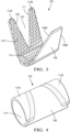
FIG. 3 illustrates an isolated isometric view of the outer ferrule ofFIG.1 in the pre-crimped condition according to some embodiments; and -
FIG. 4 illustrates an isolated isometric view of the outer ferrule ofFIG.2 in a crimped condition according to some embodiments. - This disclosure is directed to a coaxial electrical terminal with a crimped outer ferrule.
- A non-limiting example of a
coaxial terminal 100 is shown inFIGs. 1 and 2 includes anouter ferrule 102 which is an integral, single piece outer ferrule that is stamped from sheet metal, such as tin-plated brass and then formed into its desired shape using conventional metal forming techniques, such as crimping. Theouter ferrule 102 may also include a carrier strip (not shown) to facilitate handling and processing of theouter ferrule 102. The carrier strip may be cut away and removed after attaching theouter ferrule 102 to thecoaxial terminal 104 andcoaxial cable 106. - The
outer ferrule 102 has crimping wings in a double bypass arrangement that include a single trapezoidal shapedfirst crimp wing 108 extending from one side of abase portion 110 of theouter ferrule 102 and trapezoidal shaped second andthird crimp wings base portion 110. The second andthird crimp wings crimp wings 108, 112 are wrapped around and crimped to theshield conductor 114 which overlays theinner ferrule 116 of thecoaxial terminal 104. Theouter ferrule 102 secures thecoaxial terminal 104 to thecoaxial cable 106 and ensures a good quality connection between theshield conductor 114 and theinner ferrule 116. - The lengths and widths of the
crimp wings 108, 112 may be tuned for optimal mechanical, RF, and EMC performance. A rhombus shapedknurled contact pattern 118 may be applied to an inner surface of theouter ferrule 102 including thebase portion 110 and thecrimp wings 108, 112 to enhance mechanical, RF, and EMC performance. The knurledcontact pattern 118 provides multiple contact points between theouter ferrule 102 and theshield conductor 114, thereby reducing contact resistance and enhancing shielding performance. - The
first crimp wing 108 is designed to interact with the second andthird crimp wings outer edges crimp wings 108, are adjacent toinner edges crimp wings crimp wings 108, 112 provides optimal bypass interference due to the second andthird crimp wings gap 120 between them. As can be seen inFIG. 3 , thegap 120 has a width that is narrower than the width of thefirst crimp wing 108, typically about 0.5 to 1 mm narrower, preferably 0.8 mm narrower. As shown inFIG. 4 , thefirst crimp wing 108 is crimped such that it fills thegap 120 between the second andthird crimp wings edges first crimp wing 108 to be in compressive contact with the mesial (inner)edges third crimp wings first crimp wing 108 and the second andthird crimp wings FIG. 4 , increases mechanical performance without requiring excessively tight crimp heights that negatively impact RF performance of thecoaxial terminal 104. Thefirst crimp wing 108 does not overlap the second andthird crimp wings outer ferrule 102 has a generally uniform thickness that provides a reduced packaging size within an electrical connector body. The inventors have observed that the order in which thecrimp wings 108, 112 are crimped does not affect the effectiveness or strength of the attachment of theouter ferrule 102 to thecoaxial terminal 104. - While the illustrated
crimp wings gap 120 each have a trapezoidal shape, alternative embodiments may be envisioned in which they have different shapes, such as triangular or rectangular. In other alternative embodiments, the tips of the first, second, and third crimp wings and the gap near the base portion may be rounded. - Insulation strain relief is integrated into the outer ferrule design to provide mechanical robustness. The first and
second crimp wings outer insulation jacket 122 of thecoaxial cable 106 to provide robust strain relief and environmental conditioning performance. The crimp height of thesecond crimp wing 112A may be slightly higher than the crimp height of thethird crimp wing 112B to accommodate the thickness of theouter insulation jacket 122 of thecoaxial cable 106. - The
outer ferrule 102 provides the benefit of accommodating coaxial cables of different diameters. The double bypassouter ferrule 102 presented herein has been found to provide a pull off force of up to 50% greater than that of single bypass crimped outer ferrules. - While the double bypass
outer ferrule 102 shown herein is configured to use with acoaxial terminal 104 for low voltage applications e.g., less than 14 volts such as those used for digital or radio frequency signals, other embodiments may be used for a coaxial cable terminal for high voltage application, e.g., greater than 60 volts direct current (VDC) or 30 volts alternating current (VAC). The double-bypass crimp wing design may also by adapted to secure electrical terminals to solid or braided wire cables. - While the invention has been described with reference to an exemplary embodiment(s), it will be understood by those skilled in the art that various changes may be made, and equivalents may be substituted for elements thereof without departing from the scope of the invention. In addition, many modifications may be made to adapt a particular situation or material to the teachings of the invention without departing from the essential scope thereof. Therefore, it is intended that the invention is not limited to the disclosed embodiment(s), but that the invention will include all embodiments falling within the scope of the appended claims.
- As used herein, 'one or more' includes a function being performed by one element, a function being performed by more than one element, e.g., in a distributed fashion, several functions being performed by one element, several functions being performed by several elements, or any combination of the above.
- It will also be understood that, although the terms first, second, etc. are, in some instances, used herein to describe various elements, these elements should not be limited by these terms. These terms are only used to distinguish one element from another. For example, a first contact could be termed a second contact, and, similarly, a second contact could be termed a first contact, without departing from the scope of the various described embodiments. The first contact and the second contact are both contacts, but they are not the same contact.
- The terminology used in the description of the various described embodiments herein is for the purpose of describing particular embodiments only and is not intended to be limiting. As used in the description of the various described embodiments and the appended claims, the singular forms "a", "an" and "the" are intended to include the plural forms as well, unless the context clearly indicates otherwise. It will also be understood that the term "and/or" as used herein refers to and encompasses any and all possible combinations of one or more of the associated listed items. It will be further understood that the terms "includes," "including," "comprises," and/or "comprising," when used in this specification, specify the presence of stated features, integers, steps, operations, elements, and/or components, but do not preclude the presence or addition of one or more other features, integers, steps, operations, elements, components, and/or groups thereof.
- As used herein, the term "if" is, optionally, construed to mean "when" or "upon" or "in response to determining" or "in response to detecting," depending on the context. Similarly, the phrase "if it is determined" or "if [a stated condition or event] is detected" is, optionally, construed to mean "upon determining" or "in response to determining" or "upon detecting [the stated condition or event]" or "in response to detecting [the stated condition or event]," depending on the context.
- Additionally, while terms of ordinance or orientation may be used herein these elements should not be limited by these terms. All terms of ordinance or orientation, unless stated otherwise, are used for purposes distinguishing one element from another, and do not denote any particular order, order of operations, direction or orientation unless stated otherwise.
Claims (15)
- An electrical cable assembly, comprising:an electrical terminal (100) having an inner ferrule (116) disposed between an insulator surrounding a central conductor of an electrical cable and a shield conductor (114) of the electrical cable; andan outer ferrule (102) crimped to the shield conductor (114) and in compressive contact therewith, wherein the outer ferrule (102) defines a pair of crimp wings (112A, 112B) extending from a first side of a base portion (110) of the outer ferrule (102) and a single crimp wing extending from a second side of the base portion (110) opposite the first side, wherein the single crimp wing (108) is disposed within a gap (120) between the pair of crimp wings (112A, 112B).
- The electrical cable assembly in accordance with claim 1, wherein the single crimp wing (108), the pair of crimp wings (112A, 112B), and the base portion (110) are bent to form a generally cylindrical tubular shape.
- The electrical cable assembly in accordance with claim 1 or 2, wherein the outer ferrule (102) has a consistent thickness.
- The electrical cable assembly in accordance with any one of the preceding claims, wherein mesial edges of the pair of crimp wings (112A, 112B) are in compressive contact with distal edges of the single crimp wing (108).
- The electrical cable assembly in accordance with any one of the preceding claims, wherein each of the pair of crimp wings (112A, 112B) has a trapezoidal shape.
- The electrical cable assembly in accordance with claim 5, wherein each of the pair of crimp wings (112A, 112B) has a right trapezoidal shape.
- The electrical cable assembly in accordance with any one of the preceding claims, wherein the single crimp wing (108) has a trapezoidal shape.
- The electrical cable assembly in accordance with any one of the preceding claims, wherein an inner surface of the outer ferrule (102) defines a plurality of rhombus-shaped indentations.
- The electrical cable assembly in accordance with any one of the preceding claims, wherein the outer ferrule (102) is also crimped to an outer insulator surrounding a portion of the shield conductor (114) and is in compressive contact therewith.
- The electrical cable assembly in accordance with claim 9, wherein the single crimp wing (108) and one crimp wing (112A) of the pair of crimp wings (112A, 112B) is in compressive contact with the outer insulator.
- A method of forming an outer ferrule (102) configured to secure an electrical terminal (100) to an electrical cable, the method comprising:forming an outer ferrule (102) preform from sheet metal of generally uniform thickness, wherein the outer ferrule (102) preform has a central base portion (110), a pair of crimp wings (112A, 112B) extending from a first side of the base portion (110) and a single crimp wing (108) extending from a second side of the base portion (110) opposite the first side; andforming the base portion (110) to have an arcuate shape.
- The method in accordance with claim 11, further comprising:
forming a plurality of rhombus-shaped indentations in an inner surface of the outer ferrule (102) preform. - The method in accordance with claim 11 or 12, wherein the single crimp wing (108) is a trapezoidal crimp wing, wherein the pair of crimp wings (112A, 112B) define a trapezoidal gap (120) therebetween, and wherein a width of the trapezoidal crimp wing is greater than a width of the trapezoidal gap (120), wherein the width of the trapezoidal crimp wing is 0.5 to 1.0 mm greater than the width of the trapezoidal gap (120), wherein each of the pair of crimp wings (112has a right trapezoidal shape, and wherein the method further comprises:placing an exposed shield conductor (114) of the electrical cable on the base portion (110) of the outer ferrule (102) preform; andcrimping the pair of crimp wings (112A, 112B) and the single crimp wing (108) of the outer ferrule (102) preform over the exposed shield conductor (114) to form an outer ferrule (102) having a tubular shape, wherein the single crimp wing (108) is disposed within the trapezoidal gap (120), thereby pushing the pair of crimp wings (112A, 112B) apart and causing mesial edges of the pair of crimp wings (112) to be in compressive contact with distal edges of the single crimp wing (108).
- The method in accordance with claim 13, wherein the single crimp wing (108), the pair of crimp wings (112A, 112B), and the base portion (110) of the outer ferrule (102) form a generally cylindrical tubular shape, wherein the outer ferrule (102) has a consistent thickness, and wherein the method further comprises:
crimping the single crimp wing (108) and one crimp wing (112A) of the pair of crimp wings (112A, 112B) such that they are in compressive contact with an outer insulator of the electrical cable. - An electrical cable assembly, comprising:
an electrical terminal (100) having an attachment portion having a pair of crimp wings (112A, 112B) extending from a first side of a base portion (110) of the attachment portion and a single crimp wing (108) extending from a second side of the attachment portion opposite the first side, wherein the single crimp wing (108) is disposed within a gap (120) between the pair of crimp wings (112) and wherein mesial edges of the pair of crimp wings (112A, 112B) are in compressive contact with distal edges of the single crimp wing (108).
Applications Claiming Priority (1)
| Application Number | Priority Date | Filing Date | Title |
|---|---|---|---|
| US18/079,742 US20240195086A1 (en) | 2022-12-12 | 2022-12-12 | Coaxial electrical terminal with crimped outer ferrule |
Publications (1)
| Publication Number | Publication Date |
|---|---|
| EP4386995A1 true EP4386995A1 (en) | 2024-06-19 |
Family
ID=88017738
Family Applications (1)
| Application Number | Title | Priority Date | Filing Date |
|---|---|---|---|
| EP23195645.9A Pending EP4386995A1 (en) | 2022-12-12 | 2023-09-06 | Coaxial electrical terminal with crimped outer ferrule |
Country Status (3)
| Country | Link |
|---|---|
| US (1) | US20240195086A1 (en) |
| EP (1) | EP4386995A1 (en) |
| CN (1) | CN118198809A (en) |
Citations (5)
| Publication number | Priority date | Publication date | Assignee | Title |
|---|---|---|---|---|
| WO1990006005A1 (en) * | 1988-11-23 | 1990-05-31 | Gilbert Engineering Company, Inc. | Securement means for coaxial cable connector |
| EP3460916A1 (en) * | 2017-09-22 | 2019-03-27 | TE Connectivity Germany GmbH | Electrical contact device, electrical connecting unit and method for assembling an electrical cable |
| EP3528343A1 (en) * | 2018-02-16 | 2019-08-21 | Aptiv Technologies Limited | Electrical shielding member for a network connector |
| EP3641061A1 (en) * | 2018-10-19 | 2020-04-22 | Aptiv Technologies Limited | Shielded cable assembly and electromagnetic shield terminal assembly for same |
| EP3706247A2 (en) * | 2019-03-06 | 2020-09-09 | Tyco Electronics (Shanghai) Co., Ltd. | Connection terminal |
Family Cites Families (11)
| Publication number | Priority date | Publication date | Assignee | Title |
|---|---|---|---|---|
| US3032602A (en) * | 1959-12-16 | 1962-05-01 | Gen Motors Corp | Electrical connector |
| US3051773A (en) * | 1959-09-23 | 1962-08-28 | Hugh W Batcheller | Wire gripping elements and method of making and crimping same |
| US3404368A (en) * | 1965-08-04 | 1968-10-01 | Amp Inc | Electrical connector of the plug or socket variety |
| US4692122A (en) * | 1986-10-06 | 1987-09-08 | Minnesota Mining And Manufacturing Company | Electrical terminal |
| US5965847A (en) * | 1996-11-12 | 1999-10-12 | Sumitomo Wiring Systems, Ltd. | Shield connector |
| EP1319262B1 (en) * | 2000-09-15 | 2009-02-25 | Alcoa Fujikura Ltd. | Electrical terminal socket assembly for vehicular component |
| FR2877150B1 (en) * | 2004-10-27 | 2007-01-19 | Radiall Sa | METHOD FOR MOUNTING AN ELECTRICAL CONNECTOR ON A COAXIAL CABLE, AND SUCH A CONNECTOR |
| EP1764869A3 (en) * | 2005-09-16 | 2008-01-23 | Gebauer & Griller Kabelwerke Gesellschaft m.b.H. | Connecting terminal |
| US7422480B1 (en) * | 2007-04-20 | 2008-09-09 | Delphi Technologies, Inc. | Shielded electric connector and cable assembly and method for making same |
| US10008786B2 (en) * | 2016-10-28 | 2018-06-26 | Delphi Technologies, Inc. | Coaxial-cable-assembly, ferrule, and method of making the same |
| JP6745043B2 (en) * | 2017-02-03 | 2020-08-26 | 株式会社オートネットワーク技術研究所 | Shield terminal |
-
2022
- 2022-12-12 US US18/079,742 patent/US20240195086A1/en active Pending
-
2023
- 2023-09-06 EP EP23195645.9A patent/EP4386995A1/en active Pending
- 2023-11-01 CN CN202311439907.3A patent/CN118198809A/en active Pending
Patent Citations (5)
| Publication number | Priority date | Publication date | Assignee | Title |
|---|---|---|---|---|
| WO1990006005A1 (en) * | 1988-11-23 | 1990-05-31 | Gilbert Engineering Company, Inc. | Securement means for coaxial cable connector |
| EP3460916A1 (en) * | 2017-09-22 | 2019-03-27 | TE Connectivity Germany GmbH | Electrical contact device, electrical connecting unit and method for assembling an electrical cable |
| EP3528343A1 (en) * | 2018-02-16 | 2019-08-21 | Aptiv Technologies Limited | Electrical shielding member for a network connector |
| EP3641061A1 (en) * | 2018-10-19 | 2020-04-22 | Aptiv Technologies Limited | Shielded cable assembly and electromagnetic shield terminal assembly for same |
| EP3706247A2 (en) * | 2019-03-06 | 2020-09-09 | Tyco Electronics (Shanghai) Co., Ltd. | Connection terminal |
Also Published As
| Publication number | Publication date |
|---|---|
| CN118198809A (en) | 2024-06-14 |
| US20240195086A1 (en) | 2024-06-13 |
Similar Documents
| Publication | Publication Date | Title |
|---|---|---|
| CN111082235B (en) | Shielded cable assemblies and electromagnetic shielded terminal assemblies therefor | |
| US9071045B2 (en) | Terminal processing structure and terminal processing method of coaxial cable | |
| EP1701410B1 (en) | Coaxial connector with a cable gripping feature | |
| US7635282B2 (en) | Coaxial cable shielding terminal with improved press-clamping portion | |
| EP1075045B1 (en) | Grounding clip and system | |
| JP4096190B2 (en) | Shield terminal for coaxial cable | |
| CN103081227B (en) | Crimp type terminal | |
| EP2700128B1 (en) | Terminal fitting | |
| US20100297894A1 (en) | Terminal connector and wire harness | |
| WO2018080837A1 (en) | Coaxial-cable-assembly, ferrule, and method of making the same | |
| US20180123263A1 (en) | Coaxial-cable-assembly, ferrule, and method of making the same | |
| US20250007187A1 (en) | Electrical cable terminal with two piece coaxial crimped outer ferrule | |
| EP0681341A2 (en) | Insulation displacement terminal | |
| US20240195086A1 (en) | Coaxial electrical terminal with crimped outer ferrule | |
| EP2757640B1 (en) | Connecting structure for a shield wire | |
| WO2019027730A1 (en) | Shielded electrical connector assembly and method of manufacturing same | |
| US20240412895A1 (en) | Shielded electrical conductor with folded shielding layer | |
| US4540224A (en) | Grounding clip for use with shielded, jacketed flat cable | |
| EP3859895B1 (en) | Crimp barrel prepared for crimping | |
| EP4693749A1 (en) | Electrical cable terminal with crimping wings and method of manufacturing thereof | |
| US11637388B2 (en) | Ferrule for a coaxial cable terminal having overlapping crimp wings | |
| EP3425741B1 (en) | Terminal assembly for shielded cable | |
| JP2002217584A (en) | Electromagnetic wave shielding structure | |
| JP7552490B2 (en) | Connector with cable | |
| JPH05290899A (en) | Electric connection terminal |
Legal Events
| Date | Code | Title | Description |
|---|---|---|---|
| PUAI | Public reference made under article 153(3) epc to a published international application that has entered the european phase |
Free format text: ORIGINAL CODE: 0009012 |
|
| STAA | Information on the status of an ep patent application or granted ep patent |
Free format text: STATUS: THE APPLICATION HAS BEEN PUBLISHED |
|
| AK | Designated contracting states |
Kind code of ref document: A1 Designated state(s): AL AT BE BG CH CY CZ DE DK EE ES FI FR GB GR HR HU IE IS IT LI LT LU LV MC ME MK MT NL NO PL PT RO RS SE SI SK SM TR |
|
| RAP1 | Party data changed (applicant data changed or rights of an application transferred) |
Owner name: APTIV TECHNOLOGIES AG |
|
| RAP3 | Party data changed (applicant data changed or rights of an application transferred) |
Owner name: APTIV TECHNOLOGIES AG |
|
| STAA | Information on the status of an ep patent application or granted ep patent |
Free format text: STATUS: REQUEST FOR EXAMINATION WAS MADE |
|
| 17P | Request for examination filed |
Effective date: 20241218 |