EP3706247A2 - Connection terminal - Google Patents
Connection terminal Download PDFInfo
- Publication number
- EP3706247A2 EP3706247A2 EP20161251.2A EP20161251A EP3706247A2 EP 3706247 A2 EP3706247 A2 EP 3706247A2 EP 20161251 A EP20161251 A EP 20161251A EP 3706247 A2 EP3706247 A2 EP 3706247A2
- Authority
- EP
- European Patent Office
- Prior art keywords
- wing
- connection terminal
- body portion
- edge
- wires
- Prior art date
- Legal status (The legal status is an assumption and is not a legal conclusion. Google has not performed a legal analysis and makes no representation as to the accuracy of the status listed.)
- Withdrawn
Links
Images


Classifications
-
- H—ELECTRICITY
- H01—ELECTRIC ELEMENTS
- H01R—ELECTRICALLY-CONDUCTIVE CONNECTIONS; STRUCTURAL ASSOCIATIONS OF A PLURALITY OF MUTUALLY-INSULATED ELECTRICAL CONNECTING ELEMENTS; COUPLING DEVICES; CURRENT COLLECTORS
- H01R4/00—Electrically-conductive connections between two or more conductive members in direct contact, i.e. touching one another; Means for effecting or maintaining such contact; Electrically-conductive connections having two or more spaced connecting locations for conductors and using contact members penetrating insulation
- H01R4/10—Electrically-conductive connections between two or more conductive members in direct contact, i.e. touching one another; Means for effecting or maintaining such contact; Electrically-conductive connections having two or more spaced connecting locations for conductors and using contact members penetrating insulation effected solely by twisting, wrapping, bending, crimping, or other permanent deformation
- H01R4/18—Electrically-conductive connections between two or more conductive members in direct contact, i.e. touching one another; Means for effecting or maintaining such contact; Electrically-conductive connections having two or more spaced connecting locations for conductors and using contact members penetrating insulation effected solely by twisting, wrapping, bending, crimping, or other permanent deformation by crimping
- H01R4/183—Electrically-conductive connections between two or more conductive members in direct contact, i.e. touching one another; Means for effecting or maintaining such contact; Electrically-conductive connections having two or more spaced connecting locations for conductors and using contact members penetrating insulation effected solely by twisting, wrapping, bending, crimping, or other permanent deformation by crimping for cylindrical elongated bodies, e.g. cables having circular cross-section
- H01R4/184—Electrically-conductive connections between two or more conductive members in direct contact, i.e. touching one another; Means for effecting or maintaining such contact; Electrically-conductive connections having two or more spaced connecting locations for conductors and using contact members penetrating insulation effected solely by twisting, wrapping, bending, crimping, or other permanent deformation by crimping for cylindrical elongated bodies, e.g. cables having circular cross-section comprising a U-shaped wire-receiving portion
-
- H—ELECTRICITY
- H01—ELECTRIC ELEMENTS
- H01R—ELECTRICALLY-CONDUCTIVE CONNECTIONS; STRUCTURAL ASSOCIATIONS OF A PLURALITY OF MUTUALLY-INSULATED ELECTRICAL CONNECTING ELEMENTS; COUPLING DEVICES; CURRENT COLLECTORS
- H01R13/00—Details of coupling devices of the kinds covered by groups H01R12/70 or H01R24/00 - H01R33/00
- H01R13/02—Contact members
-
- H—ELECTRICITY
- H01—ELECTRIC ELEMENTS
- H01R—ELECTRICALLY-CONDUCTIVE CONNECTIONS; STRUCTURAL ASSOCIATIONS OF A PLURALITY OF MUTUALLY-INSULATED ELECTRICAL CONNECTING ELEMENTS; COUPLING DEVICES; CURRENT COLLECTORS
- H01R4/00—Electrically-conductive connections between two or more conductive members in direct contact, i.e. touching one another; Means for effecting or maintaining such contact; Electrically-conductive connections having two or more spaced connecting locations for conductors and using contact members penetrating insulation
- H01R4/10—Electrically-conductive connections between two or more conductive members in direct contact, i.e. touching one another; Means for effecting or maintaining such contact; Electrically-conductive connections having two or more spaced connecting locations for conductors and using contact members penetrating insulation effected solely by twisting, wrapping, bending, crimping, or other permanent deformation
- H01R4/18—Electrically-conductive connections between two or more conductive members in direct contact, i.e. touching one another; Means for effecting or maintaining such contact; Electrically-conductive connections having two or more spaced connecting locations for conductors and using contact members penetrating insulation effected solely by twisting, wrapping, bending, crimping, or other permanent deformation by crimping
- H01R4/188—Electrically-conductive connections between two or more conductive members in direct contact, i.e. touching one another; Means for effecting or maintaining such contact; Electrically-conductive connections having two or more spaced connecting locations for conductors and using contact members penetrating insulation effected solely by twisting, wrapping, bending, crimping, or other permanent deformation by crimping having an uneven wire-receiving surface to improve the contact
-
- H—ELECTRICITY
- H01—ELECTRIC ELEMENTS
- H01R—ELECTRICALLY-CONDUCTIVE CONNECTIONS; STRUCTURAL ASSOCIATIONS OF A PLURALITY OF MUTUALLY-INSULATED ELECTRICAL CONNECTING ELEMENTS; COUPLING DEVICES; CURRENT COLLECTORS
- H01R4/00—Electrically-conductive connections between two or more conductive members in direct contact, i.e. touching one another; Means for effecting or maintaining such contact; Electrically-conductive connections having two or more spaced connecting locations for conductors and using contact members penetrating insulation
- H01R4/24—Connections using contact members penetrating or cutting insulation or cable strands
- H01R4/2404—Connections using contact members penetrating or cutting insulation or cable strands the contact members having teeth, prongs, pins or needles penetrating the insulation
- H01R4/2407—Connections using contact members penetrating or cutting insulation or cable strands the contact members having teeth, prongs, pins or needles penetrating the insulation having saw-tooth projections
-
- H—ELECTRICITY
- H01—ELECTRIC ELEMENTS
- H01R—ELECTRICALLY-CONDUCTIVE CONNECTIONS; STRUCTURAL ASSOCIATIONS OF A PLURALITY OF MUTUALLY-INSULATED ELECTRICAL CONNECTING ELEMENTS; COUPLING DEVICES; CURRENT COLLECTORS
- H01R43/00—Apparatus or processes specially adapted for manufacturing, assembling, maintaining, or repairing of line connectors or current collectors or for joining electric conductors
- H01R43/04—Apparatus or processes specially adapted for manufacturing, assembling, maintaining, or repairing of line connectors or current collectors or for joining electric conductors for forming connections by deformation, e.g. crimping tool
- H01R43/042—Hand tools for crimping
-
- H—ELECTRICITY
- H01—ELECTRIC ELEMENTS
- H01R—ELECTRICALLY-CONDUCTIVE CONNECTIONS; STRUCTURAL ASSOCIATIONS OF A PLURALITY OF MUTUALLY-INSULATED ELECTRICAL CONNECTING ELEMENTS; COUPLING DEVICES; CURRENT COLLECTORS
- H01R43/00—Apparatus or processes specially adapted for manufacturing, assembling, maintaining, or repairing of line connectors or current collectors or for joining electric conductors
- H01R43/04—Apparatus or processes specially adapted for manufacturing, assembling, maintaining, or repairing of line connectors or current collectors or for joining electric conductors for forming connections by deformation, e.g. crimping tool
- H01R43/048—Crimping apparatus or processes
-
- H—ELECTRICITY
- H01—ELECTRIC ELEMENTS
- H01R—ELECTRICALLY-CONDUCTIVE CONNECTIONS; STRUCTURAL ASSOCIATIONS OF A PLURALITY OF MUTUALLY-INSULATED ELECTRICAL CONNECTING ELEMENTS; COUPLING DEVICES; CURRENT COLLECTORS
- H01R43/00—Apparatus or processes specially adapted for manufacturing, assembling, maintaining, or repairing of line connectors or current collectors or for joining electric conductors
- H01R43/04—Apparatus or processes specially adapted for manufacturing, assembling, maintaining, or repairing of line connectors or current collectors or for joining electric conductors for forming connections by deformation, e.g. crimping tool
- H01R43/058—Crimping mandrels
-
- H—ELECTRICITY
- H01—ELECTRIC ELEMENTS
- H01F—MAGNETS; INDUCTANCES; TRANSFORMERS; SELECTION OF MATERIALS FOR THEIR MAGNETIC PROPERTIES
- H01F5/00—Coils
- H01F5/04—Arrangements of electric connections to coils, e.g. leads
Definitions
- connection terminal In an operation of connecting electrical equipment, it is sometimes necessary to use a connection terminal to electrically connect a plurality of wires to each other in a crimped manner. For example, when connecting three wires for conveying three-phase AC current, one end of the three wires needs to be electrically connected together. To facilitate the connection, a terminal clip is crimped to one end of the three wires to achieve an electrical connection between the three wires.
- inner surfaces of the third wing and the fourth wing are provided with a plurality of second grooves.
- each second groove is formed as a slot extending in the transverse direction on the third wing, the fourth wing, and the body portion.
- an edge of each second groove is provided with second burrs extending away from the inner surfaces.
- the body portion is pre-bent to have a substantially U-shaped cross section.
- a slope is provided on an outer surface of a free end of each of the first wing, the second wing, the third wing, and the fourth wing.
- connection terminal According to embodiments of another aspect of the present disclosure, there is provided a method of connecting a plurality of wires by the connection terminal according to above mentioned embodiments, including:
- a plurality of guiding grooves having different slopes are provided on sidewalls of the U-shaped opening of the pressing die, and the plurality of guiding grooves are configured such that the second wing is bent toward the body portion prior to the first wing as the pressing die presses the connection terminal against the support portion.
- connection terminal the method of connecting a plurality of wires by such a connection terminal and a pressing die of the present disclosure, since the first wing and the second wing connected to the body portion of the connection terminal have different lengths and are provided with first grooves, in the case where the first wing and the second wing are bent to crimp the wires, the second wing is held between the first wing and the wires by the first wing, so that the wires are crimped by two layers of wings and securely retained in the connection terminals.
- a connection terminal made of a metal sheet and including: a body portion having a first edge and a second edge extending in a longitudinal direction of the body portion and opposite to each other in a transverse direction of the body portion; and a first wing and a second wing extending from the first edge and the second edge, respectively.
- the first wing and the second wing are opposite to each other in the transverse direction of the body portion, and a length of the first wing extending from the first edge is greater than that of the second wing extending from the second edge.
- Inner surfaces of the first wing, the second wing, and the body portion are provided with a plurality of first grooves.
- a pressing die adapted to press the above mentioned connection terminal
- the pressing die is provided with an opening having a substantially U-shaped cross section, into which the first wing and the second wing of the connection terminal are adapted to enter, and as the pressing die presses the connection terminal against a support portion, the first wing and the second wing are bent toward the body portion so as to crimp the wire within the connection terminal, and the first wing is located outside the second wing.
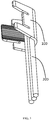
- a connection terminal is made of a metal sheet such as a single copper sheet, a single stainless steel sheet, and includes a body portion 1, a first wing 2, and a second wing 3.
- the body portion 1 has a substantially rectangular shape when unfolded into a plane, and has a first edge 11 and a second edge 12 extending in a longitudinal direction thereof and opposite to each other in a transverse direction thereof.
- the first wing 2 and the second wing 3 extend from the first edge 11 and the second edge 12, respectively.
- the first wing 2 and the second wing 3 are opposite in the transverse direction of the body portion 1, and a length of the first wing 2 extending from the first edge 11 of the body portion 1 is greater than that of the second wing 3 extending from the second edge 12.
- the second wing 3 is held between the first wing 2 and the wires 200 by the first wing 2, so that the wires 200 is crimped by two layers of wings and thus may be securely held in the connection terminal 100 and all of the wires 200 are electrically connected to each other.
- FIG. 2 is a cross-sectional view of a body portion of the connection terminal shown in FIG. 1 taken along a longitudinal direction thereof.
- inner surfaces of the first wing 2, the second wing 3 and the body portion 1 are provided with a plurality of first grooves 8.
- first grooves 8 the friction force applied to the wires 200 by the body portion 1, the first wing 2 and the second wing 3 may be increased, and the friction between the first wing 2 and the second wing 3 may also be increased, thereby retaining the wire 200 more securely in the connection terminal.
- FIG. 12 is a transverse cross-sectional view showing the connection terminal shown in FIG. 1 when a plurality of wires are connected thereto, wherein wings of the connection terminal have been bent already; and
- FIG. 13 is another transverse cross-sectional view showing the connection terminal shown in FIG. 1 when a plurality of wires are connected thereto, wherein wings of the connection terminal have been bent already;.
- connection terminal 100 is adapted to retain more than three wires 200, such as ten wires.
- the wire 200 includes a plurality of (e.g. seven) bare wires 201 and a plurality of (e.g. three) varnished wires 202.
- the varnished wire 202 includes a conductor and an insulating layer that covers the conductor. An edge of each first groove 8 is provided with first burrs 7 extending away from the inner surfaces.
- Each varnished wire 202 is disposed to be in contact with at least one of the first wing 2, the second wing 3, and the body portion 1.
- first wing 2 and the at least one fourth wing 5 are alternately arranged on the first edge 11, and the second wing 3 and the at least one third wing 4 are alternately disposed on the second edge 12.
- first wing 2 having a longer length is located between two fourth wings 5 having a shorter length
- second wing 3 having a shorter length is located between two third wings 4 having a longer length.
- connection terminal has a two-dimensional structure, and the wings performs overlapping and crimping on the wires from two dimensions, and the wings at the front end (for example, the third wing and the fourth wing) overlap towards one side of the body portion 1 to crimp the wires, and the wings at the rear end (for example, the first wing and the second wing) overlap towards the other side of the body portion 1 to crimp the wires.
- a plurality of wires are subjected to balanced force, and are pressed by a plurality of wings at a plurality of points to prevent the plurality of wires from being concentrated or twisted toward a certain portion during the crimping process, thereby more reliably retaining the plurality of wires together mechanically.
- the poor electrical contact between the wires may be avoided, and the cross-sectional structure of the finally formed wires is substantially uniform.
- FIG. 9 is a perspective view showing the connection terminal shown in FIG. 1 adapted to connect end portions of wires; and FIG. 10 is a perspective view showing the connection terminal shown in FIG. 1 adapted to connect portions of the wires each between end portions of each wire.
- connection terminal 100 may be crimped at the end portions of the plurality of wires 200 such that the plurality of wires 200 extend out of the connection terminal 100 from the same end of the connection terminal 100.
- the connection terminal 100 may be crimped at portions of the plurality of wires 200, each of which is located between the two end portions of the wire 200, that is, both end portions of each wire 200 extend out of the connection terminal 100. This increases the application flexibility of the connection terminal.
- the connection terminal 100 may crimp the wires inserted therein from both ends of the body portion 1 such that one end of one wire faces one end of the other wire.
- a first wing 2 and a second wing 3 extend from the first edge 11 and the second edge 12, respectively.
- the first wing 2 and the second wing 3 are opposite in the transverse direction of the body portion 1, and a length of the first wing 2 extending from the first edge 11 of the body portion 1 is greater than that of the second wing 3 extending from the second edge 12.
- Inner surfaces of the first wing 2, the second wing 3 and the body portion 1 are provided with a plurality of first grooves 8.
- Each of the first grooves 8 is formed as a slot extending in the transverse direction on the first wing 2, the second wing 3, and the body portion 1.
- An edge of each first groove 8 is provided with first burrs 7 extending away from the inner surfaces.
- the connection terminal 100' further includes one third wing 4 and one fourth wing 5 extending from the second edge and the first edge of the body portion 1, respectively.
- the third wing 4 is provided to be opposite to the fourth wing 5 in the transverse direction of the body portion 1, and a length of the third wing 4 extending from the second edge 12 of the body portion 1 is greater than that of the fourth wing 5 extending from the first edge 11.
- the first wing 2 and the fourth wing 5 are alternately arranged on the first edge 11, and the second wing 3 and the third wing 4 are alternately disposed on the second edge 12.
- Inner surfaces of the third wing 4 and the fourth wing 5 are provided with a plurality of second grooves 9.
- Each of the second grooves 9 is formed as a slot extending in the transverse direction on the third wing 4, the fourth wing 5, and the body portion 1.
- An edge of each second groove 9 is provided with second burrs 10 extending away from the inner surfaces.
- the body portion 1 is pre-bent to have a substantially U-shaped cross section to facilitate placement of multiple wires within a generally U-shaped configuration.
- a slope 13 is provided on an outer surface of a free end of each of the first wing 2, the second wing 3, the third wing 4, and the fourth wing 5. The slop may direct the wings to move smoothly relative to a pressing die (described in detail below).
- FIG. 5 is a schematic view showing operation principles when the connection terminal in the state of FIG. 3 is pressed by a pressing die.
- an embodiment of the present disclosure further provides a pressing die 300 adapted to press the connection terminal 100 according to any one of above-mentioned embodiments.
- the pressing die 300 is provided with an opening 301 having a substantially U-shaped cross section, into which the first wing 2, the second wing 3, the third wing 4 and the fourth wing 5 of the connection terminal 100 are adapted to enter.
- the first wing 2, the second wing 3, the third wing 4 and the fourth wing 5 are all bent toward the body portion 1 so as to retain and crimp the wires 200 within the connection terminal 100, and the first wing 2 is located outside the second wing 3, and the fourth wing 5 is located outside the third wing 4 (as shown in FIGS. 5 and 6 ).
- the guiding groove 303 is adapted to guide the second wing 3 or the fourth wing 5 having a shorter length
- the guiding groove 304 is adapted to guide the first wing 2 or the third wing 4 having a longer length
- an angle of the guiding groove 303 with respect to a vertical axis and/or a height of the guiding groove 303 protruding into the opening 301 is larger than an angle of the guiding groove 304 with respect to a vertical axis and/or a height of the guiding groove 304 protruding into the opening 301.
- the second wing 3 is held between the first wing 2 and the wires 200 by the first wing 2
- the fourth wing 5 is held between the third wing 4 and the wires 200 by the third wing 4.
- FIG. 3 is a perspective schematic view showing the connection terminal shown in FIG. 1 when three wires are connected thereto, wherein wings of the connection terminal haven' t been bent yet; and
- FIG. 4 is another perspective view showing FIG. 3 .
- an embodiment of the present disclosure further provides a method for connecting a plurality of wires 200 by the connection terminal 100 according to any of the above embodiment.
- the method includes the following steps: as shown in FIGS. 3 and 4 , pre-bending the body portion 1 of the connection terminal 100 so as to have a substantially U-shaped cross-section; placing a portion of the plurality of wires 200 within the bent body portion 1 having a substantially U-shaped cross-section; pressing the connection terminal 100 by a pressing die 300.
- the pressing die 300 is provided with an opening 301 having a substantially U-shaped cross section, into which the first wing 2, the second wing 3, the third wing 4 and the fourth wing 5 of the connection terminal 100 are adapted to enter.
- the first wing 2, the second wing 3, the third wing 4 and the fourth wing 5 are all bent toward the body portion 1 so as to retain and crimp the wires 200 within the connection terminal 100, and the first wing 2 is located outside the second wing 3, and the fourth wing 5 is located outside the third wing 4.
- connection terminal of the embodiment of the present disclosure may achieve a firm mechanical connection and a reliable electrical connection of a plurality of wires having different overall outer diameters, which widens the usage of the connection terminal and simplifies the structure of the connection terminal.
- the wires may include, for example, varnished wires and/or bare wires adapted to coils of a three-phase motor.
- the connection terminal is adapted to crimp wires with different conductor cross-sections (for example, Circular Mil Area (CMA)).
- CMA Circular Mil Area
- the milli-inch area (diameter (mm)/25.4) 2 ⁇ 106) of the wire may be in the range of 600 to 7000, for example, 600 to 3000 (model 62304-2), 1500 to 5000 (model 62306-2) and 3000-7000 (model 62304-2). Therefore, the connection terminal of the embodiment of the present disclosure may crimp the wires having different outer diameter ranges, reducing the management cost of the wires. The burrs are used to pierce the insulating layer of the wire when crimping the wire, avoiding the process of melting the insulating layer and soldering the wire.
Abstract
Description
- The present disclosure relates to a connection terminal, and more particularly to a connection terminal adapted to connect a plurality of wires, a method of connecting a plurality of wires using such a connection terminal, and a pressing die.
- In an operation of connecting electrical equipment, it is sometimes necessary to use a connection terminal to electrically connect a plurality of wires to each other in a crimped manner. For example, when connecting three wires for conveying three-phase AC current, one end of the three wires needs to be electrically connected together. To facilitate the connection, a terminal clip is crimped to one end of the three wires to achieve an electrical connection between the three wires.
- In one type of connection, the terminal clip is made of a conductive material, and the terminal clip is electrically connected to at least a part of the connected wires, so that a reliable electrical connection between all the wires may be further ensured. In the process of connecting the wires with such a terminal clip, some of the wires may move relative to the other wires under the clamping force of the terminal clip, resulting in poor electrical contact, inconsistent cross-sectional structure of the finally formed wires, and/or inability to crimp the wire securely.
- The present disclosure is aimed to address at least one aspect of the above problems and deficiencies existing in the prior art.
- At least one embodiment of the present disclosure provides a connection terminal, a method of connecting a plurality of wires using the connection terminal, and a pressing die wherein the connection terminal may securely retain the connected wires therein.
- According to embodiments of one aspect of the present disclosure, there is provided a connection terminal made of a metal sheet and including:
a body portion having a first edge and a second edge extending in a longitudinal direction of the body portion and opposite to each other in a transverse direction of the body portion; and a first wing and a second wing extending from the first edge and the second edge, respectively. The first wing and the second wing are opposite to each other in the transverse direction of the body portion, and a length of the first wing extending from the first edge is greater than that of the second wing extending from the second edge, and inner surfaces of the first wing, the second wing, and the body portion are provided with a plurality of first grooves. - According to an embodiment of the present disclosure, each first groove is formed as a slot extending in the transverse direction in the first wing, the second wing, and the body portion.
- According to another embodiment of the present disclosure, an edge of each first groove is provided with first burrs extending away from the inner surfaces.
- According to another embodiment of the present disclosure, the connection terminal further includes: at least one third wing and at least one fourth wing extending from the second edge and the first edge, respectively. Each third wing is provided to be opposite to a respective fourth wing in the transverse direction of the body portion, and a length of the third wing extending from the second edge is greater than that of the fourth wing extending from the first edge.
- According to another embodiment of the present disclosure, the first wing and the at least one fourth wing are alternately arranged on the first edge, and the second wing and the at least one third wing are alternately disposed on the second edge.
- According to another embodiment of the present disclosure, inner surfaces of the third wing and the fourth wing are provided with a plurality of second grooves.
- According to another embodiment of the present disclosure, each second groove is formed as a slot extending in the transverse direction on the third wing, the fourth wing, and the body portion.
- According to another embodiment of the present disclosure, an edge of each second groove is provided with second burrs extending away from the inner surfaces.
- According to another embodiment of the present disclosure, the body portion is pre-bent to have a substantially U-shaped cross section.
- According to another embodiment of the present disclosure, a slope is provided on an outer surface of a free end of each of the first wing, the second wing, the third wing, and the fourth wing.
- According to embodiments of another aspect of the present disclosure, there is provided a method of connecting a plurality of wires by the connection terminal according to above mentioned embodiments, including:
- pre-bending the body portion as a substantially U-shaped cross-section;
- placing a portion of the plurality of wires within the bent body portion; and
- pressing the connection terminal by a pressing die,
- wherein the pressing die is provided with an opening having a substantially U-shaped cross section, into which the first wing and the second wing of the connection terminal are adapted to enter, and
- as the pressing die presses the connection terminal against a support portion, the first wing and the second wing are bent toward the body portion so as to crimp the wire within the connection terminal, and the first wing is located outside the second wing.
- According to an embodiment of the present disclosure, a plurality of guiding grooves having different slopes are provided on sidewalls of the U-shaped opening of the pressing die, and the plurality of guiding grooves are configured such that the second wing is bent toward the body portion prior to the first wing as the pressing die presses the connection terminal against the support portion.
- According to a further aspect of the present disclosure, there is provided a pressing die adapted to press the connection terminal according to above mentioned embodiments, the pressing die is provided with an opening having a substantially U-shaped cross section, into which the first wing and the second wing of the connection terminal are adapted to enter, and as the pressing die presses the connection terminal against a support portion, the first wing and the second wing are bent toward the body portion so as to crimp the wire within the connection terminal, and the first wing is located outside the second wing.
- According to an embodiment of the present disclosure, a plurality of guiding grooves having different slopes are provided on sidewalls of the U-shaped opening of the pressing die, and the plurality of guiding grooves are configured such that the second wing is bent toward the body portion prior to the first wing as the pressing die presses the connection terminal against the support portion.
- In various above-described embodiments of the connection terminal, the method of connecting a plurality of wires by such a connection terminal and a pressing die of the present disclosure, since the first wing and the second wing connected to the body portion of the connection terminal have different lengths and are provided with first grooves, in the case where the first wing and the second wing are bent to crimp the wires, the second wing is held between the first wing and the wires by the first wing, so that the wires are crimped by two layers of wings and securely retained in the connection terminals.
- The present disclosure will be further described in detail with reference to the accompanying drawings, in which:
-
FIG. 1 is a perspective schematic view showing a connection terminal according to an exemplary embodiment of the present disclosure; -
FIG. 2 is a cross-sectional view of a body portion of the connection terminal shown inFIG. 1 taken along a longitudinal direction thereof; -
FIG. 3 is a perspective schematic view showing the connection terminal shown inFIG. 1 when three wires are connected thereto, wherein wings of the connection terminal haven't been bent yet; -
FIG. 4 is another perspective view showingFIG. 3 ; -
FIG. 5 is a schematic view showing operation principles when the connection terminal in the state ofFIG. 3 is pressed by a pressing die; -
FIG. 6 is a perspective schematic view showing the connection terminal shown inFIG. 1 when three wires are connected thereto, wherein wings of the connection terminal have been bent already; -
FIG. 7 is a transverse cross-sectional view taken along line A-A ofFIG. 6 ; -
FIG. 8 is a transverse cross-sectional view taken along line B-B ofFIG. 6 ; -
FIG. 9 is a perspective view showing the connection terminal shown inFIG. 1 adapted to connect end portions of wires; -
FIG. 10 is a perspective view showing the connection terminal shown inFIG. 1 adapted to connect portions of the wires between end portions of wire; -
FIG. 11 is a perspective schematic view showing the connection terminal shown inFIG. 1 when a plurality of wires are connected thereto, wherein wings of the connection terminal haven't been bent yet; -
FIG. 12 is a transverse cross-sectional view showing the connection terminal shown inFIG. 1 when a plurality of wires are connected thereto, wherein wings of the connection terminal have been bent already; -
FIG. 13 is another transverse cross-sectional view showing the connection terminal shown inFIG. 1 when a plurality of wires are connected thereto, wherein wings of the connection terminal have been bent already; -
FIG. 14 is a perspective schematic view showing a connection terminal according to another exemplary embodiment of the present disclosure; -
FIG. 15 is a cross-sectional view of a body portion of the connection terminal shown inFIG. 14 taken along a longitudinal direction thereof; and -
FIG. 16 is another cross-sectional view of a body portion of the connection terminal shown inFIG. 14 taken along a longitudinal direction thereof. - Although the present disclosure will be described hereinafter in detail with reference to the attached drawings showing the preferable embodiments of the present disclosure, it should be appreciated by those of ordinary skill in the art that the invention described herein may be modified and the technical effect of the present disclosure may be achieved at the same time. It should be understood that the description to the embodiments of the present disclosure in conjunction with the attached drawings is to convey a general concept of the present disclosure to the person of ordinary skill in the art, than to limit the present disclosure to the described exemplary embodiments.
- Furthermore, in the following detailed description, for purposes of explanation, numerous specific details are set forth in order to provide a thorough understanding of the disclosed embodiments. It will be apparent, however, that one or more embodiments may be practiced without these specific details. In other instances, well-known structures and devices are schematically shown in order to simplify the drawing.
- According to a general technical concept of the invention, there is provided a connection terminal made of a metal sheet and including: a body portion having a first edge and a second edge extending in a longitudinal direction of the body portion and opposite to each other in a transverse direction of the body portion; and a first wing and a second wing extending from the first edge and the second edge, respectively. The first wing and the second wing are opposite to each other in the transverse direction of the body portion, and a length of the first wing extending from the first edge is greater than that of the second wing extending from the second edge. Inner surfaces of the first wing, the second wing, and the body portion are provided with a plurality of first grooves.
- According to anther general technical concept of the invention, there is provided a method of connecting a plurality of wires using the above mentioned connection terminal, including steps of: pre-bending the body portion as a substantially U-shaped cross-section; placing a portion of the plurality of wires within the bent body portion; and pressing the connection terminal by a pressing die. The pressing die is provided with an opening having a substantially U-shaped cross section, into which the first wing and the second wing of the connection terminal are adapted to enter, and as the pressing die presses the connection terminal against a support portion, the first wing and the second wing are bent toward the body portion so as to crimp the wire within the connection terminal, and the first wing is located outside the second wing.
- According to a further general technical concept of the invention, there is provided a pressing die adapted to press the above mentioned connection terminal, the pressing die is provided with an opening having a substantially U-shaped cross section, into which the first wing and the second wing of the connection terminal are adapted to enter, and as the pressing die presses the connection terminal against a support portion, the first wing and the second wing are bent toward the body portion so as to crimp the wire within the connection terminal, and the first wing is located outside the second wing.
-
FIG. 1 is a perspective schematic view showing a connection terminal according to an exemplary embodiment of the present disclosure. - As shown in
FIG. 1 , a connection terminal according to an embodiment of the present disclosure is made of a metal sheet such as a single copper sheet, a single stainless steel sheet, and includes abody portion 1, afirst wing 2, and asecond wing 3. -
FIG. 6 is a perspective schematic view showing the connection terminal shown inFIG. 1 when three wires are connected thereto, wherein wings of the connection terminal have been bent already;FIG. 7 is a transverse cross-sectional view taken along line A-A ofFIG. 6 ; andFIG. 8 is a transverse cross-sectional view taken along line B-B ofFIG. 6 . - As shown in
FIGS. 1 ,6-8 , in an exemplary embodiment, thebody portion 1 has a substantially rectangular shape when unfolded into a plane, and has afirst edge 11 and asecond edge 12 extending in a longitudinal direction thereof and opposite to each other in a transverse direction thereof. Thefirst wing 2 and thesecond wing 3 extend from thefirst edge 11 and thesecond edge 12, respectively. Thefirst wing 2 and thesecond wing 3 are opposite in the transverse direction of thebody portion 1, and a length of thefirst wing 2 extending from thefirst edge 11 of thebody portion 1 is greater than that of thesecond wing 3 extending from thesecond edge 12. Thus, as shown inFIGS. 6 and8 , in the case where thefirst wing 2 and thesecond wing 3 are bent so as to crimp thewires 200, thesecond wing 3 is held between thefirst wing 2 and thewires 200 by thefirst wing 2, so that thewires 200 is crimped by two layers of wings and thus may be securely held in theconnection terminal 100 and all of thewires 200 are electrically connected to each other. -
FIG. 2 is a cross-sectional view of a body portion of the connection terminal shown inFIG. 1 taken along a longitudinal direction thereof. - In an exemplary embodiment, as shown in
FIGS. 1 and 2 , inner surfaces of thefirst wing 2, thesecond wing 3 and thebody portion 1 are provided with a plurality offirst grooves 8. By providing thefirst grooves 8, the friction force applied to thewires 200 by thebody portion 1, thefirst wing 2 and thesecond wing 3 may be increased, and the friction between thefirst wing 2 and thesecond wing 3 may also be increased, thereby retaining thewire 200 more securely in the connection terminal. - In one embodiment, each of the
first grooves 8 is formed as a slot extending in the transverse direction on thefirst wing 2, thesecond wing 3, and thebody portion 1. For example, nine slots, which are formed in a serration shape and each of which is symmetrical in the transverse direction, are arranged in the longitudinal direction. In this way, the retention of the connection terminal in the longitudinal direction may be increased, preventing thewires 200 from being detached from theconnection terminal 100 in the longitudinal direction. In an alternative embodiment, the first grooves may be configured as a plurality of circular protrusions or a plurality of circular recessions. -
FIG. 12 is a transverse cross-sectional view showing the connection terminal shown inFIG. 1 when a plurality of wires are connected thereto, wherein wings of the connection terminal have been bent already; andFIG. 13 is another transverse cross-sectional view showing the connection terminal shown inFIG. 1 when a plurality of wires are connected thereto, wherein wings of the connection terminal have been bent already;. - As shown in
FIGS. 1, 2 ,12 and 13 , in an exemplary embodiment, theconnection terminal 100 is adapted to retain more than threewires 200, such as ten wires. Thewire 200 includes a plurality of (e.g. seven)bare wires 201 and a plurality of (e.g. three) varnishedwires 202. The varnishedwire 202 includes a conductor and an insulating layer that covers the conductor. An edge of eachfirst groove 8 is provided withfirst burrs 7 extending away from the inner surfaces. Each varnishedwire 202 is disposed to be in contact with at least one of thefirst wing 2, thesecond wing 3, and thebody portion 1. Thus, in the case where thewires 200 are crimped by thefirst wing 2, thesecond wing 3 and thebody portion 1 by means of a pressing die 300 (described in detail below), theburrs 7 may pierce the insulating layer of the varnishedwire 202 so that theconnection terminal 100 may be electrically connected to the varnishedwire 202. Further, by means of direct contact between theconnection terminal 100 and thebare wires 201 and direct contact between thebare wires 201, all of thewires 200 including thebare wires 201 and the varnishedwires 202 are electrically connected to each other. The varnished wire is electrically connected to other wires when the insulation layer thereof is pierced, thereby avoiding the use of welding technology, reducing the cost of crimping, and reducing environmental pollution. - As shown in
FIG. 1 , in one embodiment, theconnection terminal 100 further includes at least one third wing 4 (for example, twothird wings 4 are shown inFIG. 1 ) and at least one fourth wing 5 (for example, twofourth wings 5 are shown inFIG. 1 ) extending from the second edge and the first edge of thebody portion 1, respectively. Eachthird wing 4 is provided to be opposite to a respectivefourth wing 5 in the transverse direction of thebody portion 1, and a length of thethird wing 4 extending from thesecond edge 12 of thebody portion 1 is greater than that of thefourth wing 5 extending from thefirst edge 11. Further, thefirst wing 2 and the at least onefourth wing 5 are alternately arranged on thefirst edge 11, and thesecond wing 3 and the at least onethird wing 4 are alternately disposed on thesecond edge 12. For example, as shown inFIG. 3 , thefirst wing 2 having a longer length is located between twofourth wings 5 having a shorter length, and thesecond wing 3 having a shorter length is located between twothird wings 4 having a longer length. - The connection terminal according to an embodiment of the present disclosure has a two-dimensional structure, and the wings performs overlapping and crimping on the wires from two dimensions, and the wings at the front end (for example, the third wing and the fourth wing) overlap towards one side of the
body portion 1 to crimp the wires, and the wings at the rear end (for example, the first wing and the second wing) overlap towards the other side of thebody portion 1 to crimp the wires. In this way, a plurality of wires are subjected to balanced force, and are pressed by a plurality of wings at a plurality of points to prevent the plurality of wires from being concentrated or twisted toward a certain portion during the crimping process, thereby more reliably retaining the plurality of wires together mechanically. The poor electrical contact between the wires may be avoided, and the cross-sectional structure of the finally formed wires is substantially uniform. -
FIG. 9 is a perspective view showing the connection terminal shown inFIG. 1 adapted to connect end portions of wires; andFIG. 10 is a perspective view showing the connection terminal shown inFIG. 1 adapted to connect portions of the wires each between end portions of each wire. - In one embodiment, as shown in
FIG. 9 , theconnection terminal 100 may be crimped at the end portions of the plurality ofwires 200 such that the plurality ofwires 200 extend out of theconnection terminal 100 from the same end of theconnection terminal 100. In another embodiment, as shown inFIG. 10 , theconnection terminal 100 may be crimped at portions of the plurality ofwires 200, each of which is located between the two end portions of thewire 200, that is, both end portions of eachwire 200 extend out of theconnection terminal 100. This increases the application flexibility of the connection terminal. In a further embodiment, theconnection terminal 100 may crimp the wires inserted therein from both ends of thebody portion 1 such that one end of one wire faces one end of the other wire. -
FIG. 14 is a perspective schematic view showing a connection terminal according to another exemplary embodiment of the present disclosure;FIG. 15 is a cross-sectional view of a body portion of the connection terminal 100' shown inFIG. 14 taken along a longitudinal direction thereof; andFIG. 16 is another cross-sectional view of a body portion of the connection terminal 100' shown inFIG. 14 taken along a longitudinal direction thereof. - As shown in
FIG. 14 , in an exemplary embodiment, afirst wing 2 and asecond wing 3 extend from thefirst edge 11 and thesecond edge 12, respectively. Thefirst wing 2 and thesecond wing 3 are opposite in the transverse direction of thebody portion 1, and a length of thefirst wing 2 extending from thefirst edge 11 of thebody portion 1 is greater than that of thesecond wing 3 extending from thesecond edge 12. Inner surfaces of thefirst wing 2, thesecond wing 3 and thebody portion 1 are provided with a plurality offirst grooves 8. Each of thefirst grooves 8 is formed as a slot extending in the transverse direction on thefirst wing 2, thesecond wing 3, and thebody portion 1. An edge of eachfirst groove 8 is provided withfirst burrs 7 extending away from the inner surfaces. The connection terminal 100' further includes onethird wing 4 and onefourth wing 5 extending from the second edge and the first edge of thebody portion 1, respectively. Thethird wing 4 is provided to be opposite to thefourth wing 5 in the transverse direction of thebody portion 1, and a length of thethird wing 4 extending from thesecond edge 12 of thebody portion 1 is greater than that of thefourth wing 5 extending from thefirst edge 11. Further, thefirst wing 2 and thefourth wing 5 are alternately arranged on thefirst edge 11, and thesecond wing 3 and thethird wing 4 are alternately disposed on thesecond edge 12. Inner surfaces of thethird wing 4 and thefourth wing 5 are provided with a plurality ofsecond grooves 9. Each of thesecond grooves 9 is formed as a slot extending in the transverse direction on thethird wing 4, thefourth wing 5, and thebody portion 1. An edge of eachsecond groove 9 is provided withsecond burrs 10 extending away from the inner surfaces. - As shown in
FIGS. 14 and15 , in one embodiment, no slot is provided at a portion of thebody portion 1 between thefirst wing 2 and the fourth wing 5 (or between thesecond wings 3 and the third wing 4). As shown inFIGS. 14 and16 , in an alternative embodiment, slots further are provided at a portion of thebody portion 1 between thefirst wing 2 and the fourth wing 5 (or between thesecond wing 3 and the third wing 4). - As shown in
FIGS. 1 and14 , in one embodiment, thebody portion 1 is pre-bent to have a substantially U-shaped cross section to facilitate placement of multiple wires within a generally U-shaped configuration. Aslope 13 is provided on an outer surface of a free end of each of thefirst wing 2, thesecond wing 3, thethird wing 4, and thefourth wing 5. The slop may direct the wings to move smoothly relative to a pressing die (described in detail below). -
FIG. 5 is a schematic view showing operation principles when the connection terminal in the state ofFIG. 3 is pressed by a pressing die. - Referring to
FIG. 5 , an embodiment of the present disclosure further provides apressing die 300 adapted to press theconnection terminal 100 according to any one of above-mentioned embodiments. Thepressing die 300 is provided with anopening 301 having a substantially U-shaped cross section, into which thefirst wing 2, thesecond wing 3, thethird wing 4 and thefourth wing 5 of theconnection terminal 100 are adapted to enter. As thepressing die 300 presses the connection terminal against asupport portion 400, thefirst wing 2, thesecond wing 3, thethird wing 4 and thefourth wing 5 are all bent toward thebody portion 1 so as to retain and crimp thewires 200 within theconnection terminal 100, and thefirst wing 2 is located outside thesecond wing 3, and thefourth wing 5 is located outside the third wing 4 (as shown inFIGS. 5 and6 ). - In one embodiment, a plurality of guiding
grooves U-shaped opening 301 of thepressing die 300. The plurality of guidinggrooves second wing 3 is bent toward thebody portion 1 prior to thefirst wing 2 and meanwhile thefourth wing 5 is bent toward the body portion prior to thethird wing 4 as thepressing die 300 presses the connection terminal against thesupport portion 400. For example, in the state illustrated inFIG. 5 , the guidinggroove 303 is adapted to guide thesecond wing 3 or thefourth wing 5 having a shorter length, and the guidinggroove 304 is adapted to guide thefirst wing 2 or thethird wing 4 having a longer length, and an angle of the guidinggroove 303 with respect to a vertical axis and/or a height of the guidinggroove 303 protruding into theopening 301 is larger than an angle of the guidinggroove 304 with respect to a vertical axis and/or a height of the guidinggroove 304 protruding into theopening 301. Thus, as shown inFIGS. 6-8 , in the case where the first, second, third, and fourth wings are bent so as to retain thewires 200, thesecond wing 3 is held between thefirst wing 2 and thewires 200 by thefirst wing 2, and thefourth wing 5 is held between thethird wing 4 and thewires 200 by thethird wing 4. -
FIG. 3 is a perspective schematic view showing the connection terminal shown inFIG. 1 when three wires are connected thereto, wherein wings of the connection terminal haven' t been bent yet; andFIG. 4 is another perspective view showingFIG. 3 . - Referring to
FIG. 3-5 , an embodiment of the present disclosure further provides a method for connecting a plurality ofwires 200 by theconnection terminal 100 according to any of the above embodiment. The method includes the following steps: as shown inFIGS. 3 and4 , pre-bending thebody portion 1 of theconnection terminal 100 so as to have a substantially U-shaped cross-section; placing a portion of the plurality ofwires 200 within thebent body portion 1 having a substantially U-shaped cross-section; pressing theconnection terminal 100 by apressing die 300. Thepressing die 300 is provided with anopening 301 having a substantially U-shaped cross section, into which thefirst wing 2, thesecond wing 3, thethird wing 4 and thefourth wing 5 of theconnection terminal 100 are adapted to enter. As thepressing die 300 presses the connection terminal against asupport portion 400, thefirst wing 2, thesecond wing 3, thethird wing 4 and thefourth wing 5 are all bent toward thebody portion 1 so as to retain and crimp thewires 200 within theconnection terminal 100, and thefirst wing 2 is located outside thesecond wing 3, and thefourth wing 5 is located outside thethird wing 4. -
FIG. 11 is a perspective schematic view showing the connection terminal shown inFIG. 1 when a plurality of wires are connected thereto, wherein wings of the connection terminal haven't been bent yet. Theconnection terminal 100 is adapted to retain more than three (for example 10)wires 200. Thewire 200 includes a plurality of (e.g. seven)bare wires 201 and a plurality of (e.g. three) varnishedwires 202. The operation of connecting the ten wires shown inFIG. 11 is similar to the operation of connecting the three wires shown inFIG. 5 , and will not be described again. - According to the connection terminal of the above-described embodiment of the present disclosure, the connection terminal of the embodiment of the present disclosure may achieve a firm mechanical connection and a reliable electrical connection of a plurality of wires having different overall outer diameters, which widens the usage of the connection terminal and simplifies the structure of the connection terminal. The wires may include, for example, varnished wires and/or bare wires adapted to coils of a three-phase motor. The connection terminal is adapted to crimp wires with different conductor cross-sections (for example, Circular Mil Area (CMA)). In one embodiment, the milli-inch area (diameter (mm)/25.4) 2∗106) of the wire may be in the range of 600 to 7000, for example, 600 to 3000 (model 62304-2), 1500 to 5000 (model 62306-2) and 3000-7000 (model 62304-2). Therefore, the connection terminal of the embodiment of the present disclosure may crimp the wires having different outer diameter ranges, reducing the management cost of the wires. The burrs are used to pierce the insulating layer of the wire when crimping the wire, avoiding the process of melting the insulating layer and soldering the wire.
- It should be appreciated for those skilled in this art that the above embodiments are intended to be illustrated, and not restrictive. For example, many modifications may be made to the above embodiments by those skilled in this art, and various features described in different embodiments may be freely combined with each other without conflicting in configuration or principle.
- Although several exemplary embodiments have been shown and described, it would be appreciated by those skilled in the art that various changes or modifications may be made in these embodiments without departing from the principles and spirit of the disclosure, the scope of which is defined in the claims and their equivalents.
- As used herein, an element recited in the singular and proceeded with the word "a" or "an" should be understood as not excluding plural of said elements or steps, unless such exclusion is explicitly stated. Furthermore, references to "one embodiment" of the present disclosure are not intended to be interpreted as excluding the existence of additional embodiments that also incorporate the recited features. Moreover, unless explicitly stated to the contrary, embodiments "comprising" or "having" an element or a plurality of elements having a particular property may include additional such elements not having that property.
Claims (14)
- A connection terminal made of a metal sheet and comprising:a body portion (1) having a first edge (11) and a second edge (12) extending in a longitudinal direction of the body portion and opposite to each other in a transverse direction of the body portion; anda first wing (2) and a second wing (3) extending from the first edge and the second edge, respectively,wherein the first wing and the second wing are opposite to each other in the transverse direction of the body portion, and a length of the first wing extending from the first edge is greater than that of the second wing extending from the second edge, andwherein inner surfaces of the first wing, the second wing, and the body portion are provided with a plurality of first grooves (8).
- The connection terminal of claim 1 wherein
each first groove is formed as a slot extending in the transverse direction in the first wing, the second wing, and the body portion. - The connection terminal of claim 2, wherein
an edge of each first groove is provided with first burrs (7) extending away from the inner surfaces. - The connection terminal according to any one of claims 1 to 3, further comprising:at least one third wing (4) and at least one fourth wing (5) extending from the second edge and the first edge, respectively,wherein each third wing is provided to be opposite to a respective fourth wing in the transverse direction of the body portion, and a length of the third wing extending from the second edge is greater than that of the fourth wing extending from the first edge.
- The connection terminal of claim 4, wherein
the first wing and the at least one fourth wing are alternately arranged on the first edge, and the second wing and the at least one third wing are alternately disposed on the second edge. - The connection terminal according to claim 4 or 5, wherein
inner surfaces of the third wing and the fourth wing are provided with a plurality of second grooves (9). - The connection terminal of claim 6, wherein
each second groove is formed as a slot extending in the transverse direction on the third wing, the fourth wing, and the body portion. - The connection terminal of claim 7, wherein
an edge of each second groove is provided with second burrs (10) extending away from the inner surfaces. - The connection terminal according to any one of claims 1 to 8, wherein
the body portion is pre-bent to have a substantially U-shaped cross section. - The connection terminal according to any one of claims 4-9, wherein
a slope (13) is provided on an outer surface of a free end of each of the first wing, the second wing, the third wing, and the fourth wing. - A method of connecting a plurality of wires by the connection terminal (100) according to any one of claims 1-10, comprising steps of:pre-bending the body portion as a substantially U-shaped cross-section;placing a portion of the plurality of wires (200) within the bent body portion; andpressing the connection terminal by a pressing die (300);wherein the pressing die is provided with an opening (301) having a substantially U-shaped cross section, into which the first wing (2) and the second wing (3) of the connection terminal are adapted to enter; andas the pressing die (300) presses the connection terminal against a support portion (400), the first wing and the second wing are bent toward the body portion so as to crimp the wire within the connection terminal, and the first wing is located outside the second wing.
- The method of claim 11 wherein
a plurality of guiding grooves (303, 304) having different slopes are provided on sidewalls of the U-shaped opening of the pressing die, and
the plurality of guiding grooves are configured such that the second wing is bent toward the body portion prior to the first wing as the pressing die (300) presses the connection terminal against the support portion (400). - A pressing die (300) adapted to press the connection terminal (100) according to any one of claims 1 to 10, the pressing die is provided with an opening (301) having a substantially U-shaped cross section, into which the first wing (2) and the second wing (3) of the connection terminal are adapted to enter, and
as the pressing die (300) presses the connection terminal against a support portion (400), the first wing and the second wing are bent toward the body portion so as to crimp the wire within the connection terminal, and the first wing is located outside the second wing. - The pressing die according to claim 13, wherein
a plurality of guiding grooves (303, 304) having different slopes are provided on sidewalls of the U-shaped opening of the pressing die, and
the plurality of guiding grooves are configured such that the second wing is bent toward the body portion prior to the first wing as the pressing die (300) presses the connection terminal against the support portion (400).
Applications Claiming Priority (1)
| Application Number | Priority Date | Filing Date | Title |
|---|---|---|---|
| CN201910170433.4A CN111668624A (en) | 2019-03-06 | 2019-03-06 | Connection terminal, method for holding a plurality of wires by using the connection terminal, and press die |
Publications (2)
| Publication Number | Publication Date |
|---|---|
| EP3706247A2 true EP3706247A2 (en) | 2020-09-09 |
| EP3706247A3 EP3706247A3 (en) | 2020-11-25 |
Family
ID=69779861
Family Applications (1)
| Application Number | Title | Priority Date | Filing Date |
|---|---|---|---|
| EP20161251.2A Withdrawn EP3706247A3 (en) | 2019-03-06 | 2020-03-05 | Connection terminal |
Country Status (4)
| Country | Link |
|---|---|
| US (1) | US20200287300A1 (en) |
| EP (1) | EP3706247A3 (en) |
| JP (1) | JP2020145190A (en) |
| CN (1) | CN111668624A (en) |
Families Citing this family (3)
| Publication number | Priority date | Publication date | Assignee | Title |
|---|---|---|---|---|
| US11664608B2 (en) * | 2020-03-20 | 2023-05-30 | Lear Corporation | Electrical assembly and method |
| DE202021103144U1 (en) * | 2021-06-10 | 2021-06-17 | Ka Group Ag | Crimp connector |
| US20230122329A1 (en) * | 2021-10-18 | 2023-04-20 | Abb Schweiz Ag | Linearized magnet wire connector |
Family Cites Families (11)
| Publication number | Priority date | Publication date | Assignee | Title |
|---|---|---|---|---|
| US2783447A (en) * | 1956-03-15 | 1957-02-26 | Aircraft Marine Prod Inc | Electrical connector |
| US3032602A (en) * | 1959-12-16 | 1962-05-01 | Gen Motors Corp | Electrical connector |
| DE2503580A1 (en) * | 1975-01-29 | 1976-08-05 | Grote & Hartmann | Connecting claw for enamelled wires - is stamped in one piece from metal sheet and clamped over wire with its sharp points biting through insulating enamel |
| JPS5577368U (en) * | 1978-11-22 | 1980-05-28 | ||
| JPS55105267U (en) * | 1979-01-20 | 1980-07-23 | ||
| JP2003249284A (en) * | 2002-02-25 | 2003-09-05 | Auto Network Gijutsu Kenkyusho:Kk | Crimp style terminal for aluminum wire |
| JP5065124B2 (en) * | 2008-03-31 | 2012-10-31 | 古河電気工業株式会社 | Crimp terminal |
| JP5757226B2 (en) * | 2011-12-12 | 2015-07-29 | 株式会社オートネットワーク技術研究所 | Terminal and electric wire with terminal |
| US9343820B2 (en) * | 2013-01-11 | 2016-05-17 | Tyco Electronics Corporation | Crimp contact and cable assembly including the same |
| JP6163691B2 (en) * | 2013-07-12 | 2017-07-19 | 株式会社岩沼精工 | Crimping terminal manufacturing method and crimping terminal |
| JP6423333B2 (en) * | 2015-12-16 | 2018-11-14 | 矢崎総業株式会社 | Crimp terminal and electric wire with terminal |
-
2019
- 2019-03-06 CN CN201910170433.4A patent/CN111668624A/en active Pending
-
2020
- 2020-03-02 JP JP2020034590A patent/JP2020145190A/en active Pending
- 2020-03-05 EP EP20161251.2A patent/EP3706247A3/en not_active Withdrawn
- 2020-03-06 US US16/811,491 patent/US20200287300A1/en not_active Abandoned
Also Published As
| Publication number | Publication date |
|---|---|
| EP3706247A3 (en) | 2020-11-25 |
| US20200287300A1 (en) | 2020-09-10 |
| CN111668624A (en) | 2020-09-15 |
| JP2020145190A (en) | 2020-09-10 |
Similar Documents
| Publication | Publication Date | Title |
|---|---|---|
| EP3706247A2 (en) | Connection terminal | |
| EP2309599A1 (en) | Terminal clamp and wire with terminal clamp | |
| JP6685353B2 (en) | Cable assembly | |
| JP2005050736A (en) | Method of manufacturing terminal crimping structure to aluminum wire and aluminum wire with terminal | |
| JP6652583B2 (en) | Wire with terminal | |
| EP2323225A1 (en) | Terminal metal fitting | |
| EP2808947A1 (en) | Crimp terminal, crimp connection structure, and method for manufacturing crimp connection structure | |
| EP1981123A2 (en) | A terminal fitting and crimping method therefor | |
| US10498048B2 (en) | Wire with terminal having a core crimping portion with enlarged diameter portion and a recess in the enlarged diameter portion | |
| US3243757A (en) | Electrical connections | |
| KR0148394B1 (en) | Connector crimping electric terminal | |
| EP2147480A1 (en) | Electrical male terminal | |
| CN103222131A (en) | Terminal assembly and method for connecting an electric wire to a terminal element | |
| WO2015053182A1 (en) | Crimp terminal | |
| JP6605970B2 (en) | Electric wire with terminal, wire harness | |
| CN209880875U (en) | Connecting terminal and pressing die | |
| CN111247605B (en) | Pipe conductor and conductive path | |
| JPH0546672B2 (en) | ||
| KR20160119689A (en) | Coil end connecting structure | |
| JP2007226975A (en) | Connecting member | |
| JP2019046655A (en) | Manufacturing method of electric wire with terminal, electric wire with terminal, and terminal crimp device with terminal | |
| EP3989363A1 (en) | Electrical crimp terminal | |
| JP7126936B2 (en) | Metal terminals and wires with terminals | |
| WO2014129605A1 (en) | Method for producing connecting structure, connecting structure, and crimping device | |
| JP2021190409A (en) | Crimping structure of aluminum wire and terminal fitting |
Legal Events
| Date | Code | Title | Description |
|---|---|---|---|
| PUAI | Public reference made under article 153(3) epc to a published international application that has entered the european phase |
Free format text: ORIGINAL CODE: 0009012 |
|
| STAA | Information on the status of an ep patent application or granted ep patent |
Free format text: STATUS: REQUEST FOR EXAMINATION WAS MADE |
|
| 17P | Request for examination filed |
Effective date: 20200324 |
|
| AK | Designated contracting states |
Kind code of ref document: A2 Designated state(s): AL AT BE BG CH CY CZ DE DK EE ES FI FR GB GR HR HU IE IS IT LI LT LU LV MC MK MT NL NO PL PT RO RS SE SI SK SM TR |
|
| AX | Request for extension of the european patent |
Extension state: BA ME |
|
| PUAL | Search report despatched |
Free format text: ORIGINAL CODE: 0009013 |
|
| AK | Designated contracting states |
Kind code of ref document: A3 Designated state(s): AL AT BE BG CH CY CZ DE DK EE ES FI FR GB GR HR HU IE IS IT LI LT LU LV MC MK MT NL NO PL PT RO RS SE SI SK SM TR |
|
| AX | Request for extension of the european patent |
Extension state: BA ME |
|
| RIC1 | Information provided on ipc code assigned before grant |
Ipc: H01R 4/18 20060101AFI20201021BHEP Ipc: H01F 5/04 20060101ALN20201021BHEP |
|
| STAA | Information on the status of an ep patent application or granted ep patent |
Free format text: STATUS: EXAMINATION IS IN PROGRESS |
|
| 17Q | First examination report despatched |
Effective date: 20220413 |
|
| STAA | Information on the status of an ep patent application or granted ep patent |
Free format text: STATUS: THE APPLICATION IS DEEMED TO BE WITHDRAWN |
|
| 18D | Application deemed to be withdrawn |
Effective date: 20220824 |