EP4386990A1 - Antenne et coupleur associé pour réaliser un déport d'une fonction antennaire ainsi que dispositif communicant correspondant - Google Patents
Antenne et coupleur associé pour réaliser un déport d'une fonction antennaire ainsi que dispositif communicant correspondant Download PDFInfo
- Publication number
- EP4386990A1 EP4386990A1 EP23217008.4A EP23217008A EP4386990A1 EP 4386990 A1 EP4386990 A1 EP 4386990A1 EP 23217008 A EP23217008 A EP 23217008A EP 4386990 A1 EP4386990 A1 EP 4386990A1
- Authority
- EP
- European Patent Office
- Prior art keywords
- antenna
- coupler
- pattern
- housing
- point
- Prior art date
- Legal status (The legal status is an assumption and is not a legal conclusion. Google has not performed a legal analysis and makes no representation as to the accuracy of the status listed.)
- Granted
Links
Images

Classifications
-
- H—ELECTRICITY
- H01—ELECTRIC ELEMENTS
- H01Q—ANTENNAS, i.e. RADIO AERIALS
- H01Q5/00—Arrangements for simultaneous operation of antennas on two or more different wavebands, e.g. dual-band or multi-band arrangements
- H01Q5/40—Imbricated or interleaved structures; Combined or electromagnetically coupled arrangements, e.g. comprising two or more non-connected fed radiating elements
- H01Q5/45—Imbricated or interleaved structures; Combined or electromagnetically coupled arrangements, e.g. comprising two or more non-connected fed radiating elements using two or more feeds in association with a common reflecting, diffracting or refracting device
- H01Q5/47—Imbricated or interleaved structures; Combined or electromagnetically coupled arrangements, e.g. comprising two or more non-connected fed radiating elements using two or more feeds in association with a common reflecting, diffracting or refracting device with a coaxial arrangement of the feeds
-
- H—ELECTRICITY
- H01—ELECTRIC ELEMENTS
- H01Q—ANTENNAS, i.e. RADIO AERIALS
- H01Q5/00—Arrangements for simultaneous operation of antennas on two or more different wavebands, e.g. dual-band or multi-band arrangements
- H01Q5/30—Arrangements for providing operation on different wavebands
- H01Q5/307—Individual or coupled radiating elements, each element being fed in an unspecified way
- H01Q5/342—Individual or coupled radiating elements, each element being fed in an unspecified way for different propagation modes
- H01Q5/357—Individual or coupled radiating elements, each element being fed in an unspecified way for different propagation modes using a single feed point
- H01Q5/364—Creating multiple current paths
- H01Q5/371—Branching current paths
-
- H—ELECTRICITY
- H01—ELECTRIC ELEMENTS
- H01Q—ANTENNAS, i.e. RADIO AERIALS
- H01Q1/00—Details of, or arrangements associated with, antennas
- H01Q1/36—Structural form of radiating elements, e.g. cone, spiral, umbrella; Particular materials used therewith
- H01Q1/38—Structural form of radiating elements, e.g. cone, spiral, umbrella; Particular materials used therewith formed by a conductive layer on an insulating support
-
- G—PHYSICS
- G01—MEASURING; TESTING
- G01F—MEASURING VOLUME, VOLUME FLOW, MASS FLOW OR LIQUID LEVEL; METERING BY VOLUME
- G01F15/00—Details of, or accessories for, apparatus of groups G01F1/00 - G01F13/00 insofar as such details or appliances are not adapted to particular types of such apparatus
- G01F15/06—Indicating or recording devices
- G01F15/065—Indicating or recording devices with transmission devices, e.g. mechanical
- G01F15/066—Indicating or recording devices with transmission devices, e.g. mechanical involving magnetic transmission devices
-
- G—PHYSICS
- G01—MEASURING; TESTING
- G01F—MEASURING VOLUME, VOLUME FLOW, MASS FLOW OR LIQUID LEVEL; METERING BY VOLUME
- G01F15/00—Details of, or accessories for, apparatus of groups G01F1/00 - G01F13/00 insofar as such details or appliances are not adapted to particular types of such apparatus
- G01F15/14—Casings, e.g. of special material
-
- H—ELECTRICITY
- H01—ELECTRIC ELEMENTS
- H01Q—ANTENNAS, i.e. RADIO AERIALS
- H01Q1/00—Details of, or arrangements associated with, antennas
- H01Q1/12—Supports; Mounting means
- H01Q1/22—Supports; Mounting means by structural association with other equipment or articles
- H01Q1/2208—Supports; Mounting means by structural association with other equipment or articles associated with components used in interrogation type services, i.e. in systems for information exchange between an interrogator/reader and a tag/transponder, e.g. in Radio Frequency Identification [RFID] systems
- H01Q1/2233—Supports; Mounting means by structural association with other equipment or articles associated with components used in interrogation type services, i.e. in systems for information exchange between an interrogator/reader and a tag/transponder, e.g. in Radio Frequency Identification [RFID] systems used in consumption-meter devices, e.g. electricity, gas or water meters
-
- H—ELECTRICITY
- H01—ELECTRIC ELEMENTS
- H01Q—ANTENNAS, i.e. RADIO AERIALS
- H01Q1/00—Details of, or arrangements associated with, antennas
- H01Q1/12—Supports; Mounting means
- H01Q1/22—Supports; Mounting means by structural association with other equipment or articles
- H01Q1/225—Supports; Mounting means by structural association with other equipment or articles used in level-measurement devices, e.g. for level gauge measurement
-
- H—ELECTRICITY
- H01—ELECTRIC ELEMENTS
- H01Q—ANTENNAS, i.e. RADIO AERIALS
- H01Q1/00—Details of, or arrangements associated with, antennas
- H01Q1/12—Supports; Mounting means
- H01Q1/22—Supports; Mounting means by structural association with other equipment or articles
- H01Q1/24—Supports; Mounting means by structural association with other equipment or articles with receiving set
- H01Q1/241—Supports; Mounting means by structural association with other equipment or articles with receiving set used in mobile communications, e.g. GSM
-
- H—ELECTRICITY
- H01—ELECTRIC ELEMENTS
- H01Q—ANTENNAS, i.e. RADIO AERIALS
- H01Q1/00—Details of, or arrangements associated with, antennas
- H01Q1/48—Earthing means; Earth screens; Counterpoises
-
- H—ELECTRICITY
- H01—ELECTRIC ELEMENTS
- H01Q—ANTENNAS, i.e. RADIO AERIALS
- H01Q1/00—Details of, or arrangements associated with, antennas
- H01Q1/50—Structural association of antennas with earthing switches, lead-in devices or lightning protectors
-
- H—ELECTRICITY
- H01—ELECTRIC ELEMENTS
- H01Q—ANTENNAS, i.e. RADIO AERIALS
- H01Q1/00—Details of, or arrangements associated with, antennas
- H01Q1/52—Means for reducing coupling between antennas; Means for reducing coupling between an antenna and another structure
-
- H—ELECTRICITY
- H01—ELECTRIC ELEMENTS
- H01Q—ANTENNAS, i.e. RADIO AERIALS
- H01Q25/00—Antennas or antenna systems providing at least two radiating patterns
- H01Q25/04—Multimode antennas
-
- H—ELECTRICITY
- H01—ELECTRIC ELEMENTS
- H01Q—ANTENNAS, i.e. RADIO AERIALS
- H01Q3/00—Arrangements for changing or varying the orientation or the shape of the directional pattern of the waves radiated from an antenna or antenna system
- H01Q3/24—Arrangements for changing or varying the orientation or the shape of the directional pattern of the waves radiated from an antenna or antenna system varying the orientation by switching energy from one active radiating element to another, e.g. for beam switching
-
- H—ELECTRICITY
- H01—ELECTRIC ELEMENTS
- H01Q—ANTENNAS, i.e. RADIO AERIALS
- H01Q5/00—Arrangements for simultaneous operation of antennas on two or more different wavebands, e.g. dual-band or multi-band arrangements
- H01Q5/30—Arrangements for providing operation on different wavebands
- H01Q5/307—Individual or coupled radiating elements, each element being fed in an unspecified way
-
- H—ELECTRICITY
- H01—ELECTRIC ELEMENTS
- H01Q—ANTENNAS, i.e. RADIO AERIALS
- H01Q9/00—Electrically-short antennas having dimensions not more than twice the operating wavelength and consisting of conductive active radiating elements
- H01Q9/04—Resonant antennas
- H01Q9/30—Resonant antennas with feed to end of elongated active element, e.g. unipole
- H01Q9/42—Resonant antennas with feed to end of elongated active element, e.g. unipole with folded element, the folded parts being spaced apart a small fraction of the operating wavelength
Definitions
- the present invention relates to an antenna and an associated coupler making it possible to passively deport an antenna function. It also relates to a communicating device comprising such an antenna capable of operating with such a coupler.
- a radio device usually includes an internal antenna (often perfectly integrated into the device) and a connection to an external antenna to allow switching from one antenna to another depending on the conditions of use, for example when the reception conditions by the radio antenna is bad.
- such a device comprises two separate radio channels, each channel being connected either to the internal antenna or to the connection to the external antenna.
- a radio frequency or mechanical switch is used to switch from one channel to another.
- a radio frequency switch requires a mechanism for detecting the presence of an external connection which can prove costly, bulky and harmful to radio performance by adding attenuation.
- the detection system also presents a consumption problem (especially important for battery-powered devices).
- the invention relates, according to a second aspect, to a coupler of a communicating device comprising a rectangular substrate comprising a coupling pattern printed on one face, the coupling pattern comprising a metallic zone complementary to a non-metallic zone of an antenna intended to be in front and distance from the coupler so that the coupler recovers the signal radiated by the antenna.
- the coupler and the antenna are not in contact so there is no need to add additional connection elements. This is particularly advantageous when the communicating device is a smart water meter where waterproofing is required to comply with IP67 protection.
- the internal antenna therefore behaves like a conventional antenna when used alone and allows the signal to be shifted by transmitting it to the coupler when the latter is positioned in front of the antenna without having to change the radio path.
- the presence of a coupler near the antenna forces the latter to function as a coupler.
- the useful signal is no longer radiated directly by the antenna but transmitted to a remote external antenna via the adjacent coupler.
- the coupler and the antenna are not in direct contact which allows electrical insulation between the two (useful in the case of electricity meters). Furthermore, switching from one operating mode to another does not require any electronic or software action: the presence of the coupler allows you to switch from internal antenna radiation mode to coupling to external antenna mode.
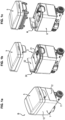
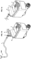
- THE figures 1a, 1b, 1c , 1d, 1e illustrate several views of a communicating device D comprising an enclosure 1 housing an electronic card 6 as well as electronic components (not visible).
- the enclosure 1 has a bottom 11 and four walls 12 (two are visible in the figures) rising from the bottom 11.
- the enclosure 1 defines a volume which houses the electronics.
- An antenna A called internal antenna is connected to the electronic card 6 and allows the communicating device D to transmit and receive signals.
- the internal antenna A is in the form of a plate of generally rectangular shape.
- the electronic card 6 provides all the radio processing necessary for communication.
- Such a communicating device D is for example a water meter for which periodic readings must be carried out remotely. More generally, we note that the invention applies to all communicating devices.
- the internal antenna A projects from the enclosure 1 and is protected by a cover 2 comprising a housing for the internal antenna A and which closes the enclosure 1.
- the cover 2 has a main wall 21 which allows the enclosure 1 to be closed while being parallel to the bottom 11 and a secondary wall 22 projecting from the main wall 21 in which the internal antenna A is housed.
- the secondary wall 22 has sufficient thickness to accommodate the internal antenna 1.
- the device communicating with the cover 2 and the enclosure 1 assembled does not allow the internal antenna A to be seen.
- a cover 5 clips onto the cover 2 to protect everything as illustrated in the figure 1a .
- the enclosure 1, the cover 2, the cover 5 are preferably made of plastic. Depending on the application, the enclosure is filled with a waterproof protective gel to protect the electronics housed there. Indeed, the communicating device can be used as a smart water meter and must be waterproof.
- the cover 2 comprises, opposite and at a distance from the secondary wall 22, an auxiliary wall 23.
- the secondary wall 22 and the auxiliary wall 23 together define a groove 24 which makes it possible to receive a coupler C which is in the form of a plate of generally rectangular shape.
- a coupler C is removable and is placed in the groove 24 opposite the internal antenna A.
- the groove 24 also includes elements for holding the coupler C opposite the internal antenna A.
- the coupler C is provided, for example with a coaxial connector 3 to which a coaxial cable 4 can be connected. At the end of the coaxial cable is connected an external Aext antenna. To connect the coupler to the Aext external antenna, you must provide a suitable 50 Ohm connector.
- the groove 24 and the secondary wall 22 have dimensions which make it possible to position the coupler C at a distance from the antenna A of between 1 and 5 mm, preferably 2 mm. In other words, it involves positioning the coupler C as close as possible to the antenna A to favor the coupling C of the signal radiated by the antenna A.
- the groove 24 is further shaped to allow the coupler C to be precisely positioned opposite the antenna A so that the coupling is optimal with the least possible loss.
- the coupler C is a passive component which is not in electrical contact with the antenna A, which makes it possible to avoid compromising the communicating device D.
- to position the coupler C it is simply a matter of placing it in the slot 24 provided for this purpose. So there is no need to disassemble it or come into contact with the electronics inside.
- the protection index, noted as IP is therefore not altered.
- Such a communicating device has two operating modes.
- a first mode comprising only the antenna A which makes it possible to radiate a radio signal (see the figures 1b and 1c ) or receive a radio signal.
- a second mode comprising the antenna A and the coupler C so as to deport the signal radiated by the antenna A towards the external antenna (see the figures 1d and 1e ).
- the transmission/reception of the radio signal is done by the external antenna Aext.
- Switching from one mode to another does not require any software action or the presence of a switch. It is only a matter of positioning the coupler C in the groove 24 provided for this purpose.
- the communicating device is such that it preferably operates in the LTE bands 20 and 8 (that is to say in the 800 MHz and 900 MHz bands). These bands are particularly used in the field of smart meters, for example for water meters. Alternatively, it is the definition of the coupler C and the internal antenna A which allows the operating bands to be adjusted.
- FIG. 2 illustrates in detail an embodiment of the antenna A adapted to be integrated into the communicating device D previously described.
- the antenna A is a printed antenna comprising a substrate 100 made of dielectric material comprising a feed point E of the antenna A and a first grounding point GND#1 connected to a ground plane (not shown) of antenna A.
- Feed point E is the entry point of the radio signal that antenna A must radiate (in the direction of transmission).
- the substrate 100 is of generally rectangular shape and extends in a transverse direction X and longitudinal direction Z.
- the metallic antenna pattern 101 is for example copper and is printed using techniques well known to those skilled in the art.
- the metallic antenna pattern 101 forms an open loop from the feed point E to the first grounding point GND#1, the loop defining a non-metallic zone 103 at its center.
- the fact that the antennal pattern 101 forms an open loop (in fact almost closed) allows the radiation of the radio signal. Furthermore, the pattern 101 being an almost closed loop allows the antenna to couple to the coupler C opposite.
- the non-metallic zone 102 is preferably rectangular. Other forms are possible.
- the antenna A is adapted to operate, in transmission, alone to radiate a radio signal or in association with a coupler C arranged opposite and at a distance from the antenna A so as to recover the signal radiated by the antenna A, the coupler C comprising, as such, a metallic zone 203 complementary to the non-metallic zone 103 opposite.
- the antennal pattern 101 has a shape which is adapted to the envisaged application in terms of frequencies of use.
- the antennal pattern 101 comprises since, the feed point E a first pattern M1 in one piece of metal consisting of two longitudinal branches 104, 105 spaced apart from each other, a transverse branch 106 connecting the two longitudinal branches 104, 105 , a first longitudinal branch 104 extending from the supply point E, a second longitudinal branch 105 extending from the transverse branch 106 parallel to the first branch 104.
- This first pattern M1 is mainly U-shaped. branches which constitute the first pattern M1 have varied thicknesses.
- a fourth branch 114 is present here in the extension of the transverse branch 106 of the U.
- a second one-piece metal pattern M2 extends from the first grounding point GND#1 connected to a ground plane. It comprises a longitudinal branch 107 which extends from the first point GND#1 followed by a transverse branch 108 parallel to and at a distance from the transverse branch 105 of the first one-piece pattern M1, the transverse branch 107 of the second one-piece pattern (M2) ending at a distance close to 1 to 3 mm from the second longitudinal branch 105 of the first pattern M1 without touching it.
- the second pattern M2 makes it possible to form the open loop with the first pattern M1 and are adapted according to the desired radiation for the antenna A.
- a third metallic pattern M3 extends from a second grounding point GND#2 of the antenna A and makes it possible to adjust the adaptation of the antenna A: a longitudinal branch 109 extends from the second point GND #2 for grounding followed by a transverse branch 110 which is parallel to the transverse branch 106 of the first pattern M1.
- FIG. 3 illustrates in detail an embodiment of a coupler C adapted to be integrated into the communicating device D previously described.
- the coupler C comprises a substrate 200 made of dielectric material and comprising a coupling pattern 201 printed on a face 202, the coupling pattern 201.
- the coupling pattern 201 comprises a metallic zone 203 complementary to the non-metallic zone 103 of the antenna A intended to be opposite and at a distance from the coupler C so that the coupler C recovers the signal radiated by the antenna A.
- the metallic zone 203 is extended by a longitudinal branch which is connected by a connector 300 to an output S of the coupler C.
- the connector 300 is adapted to 50 Ohm.
- the substrate 200 has a rectangular part 200a from which extends a tab 200b which makes it possible to connect a coaxial connector 3 to the coupler C and in particular to the output S of the coupler C.
- the connector 3 is placed on a face opposite to that on which The coupling pattern 201 is printed.
- Connector 3 is connected to a coaxial cable connected to the external Aext antenna.
- the coupling pattern 201 therefore mainly presents a rectangular metallic zone 203 from which branches 204, 205, 206, 207, 208, 209 extend which make it possible to adjust the adaptation of the coupler C and to ensure the connections of the coupler C to connector 3.
- the metal zone 203 is therefore surrounded by a loop.
- Longitudinal branches 205, 209 are printed on the substrate to be opposite the branches 107, 109 of the antenna A which are connected to the grounding points GND#1, GND#2.
- the branches 205, 209 also make it possible to capture the signal coming from antenna A and thus improve the coupling.
- the rectangular metallic zone 202 when it is opposite the non-metallic zone of the antenna A makes it possible to recover the signal radiated by the antenna A and to bring it towards the output S of the coupler (in transmission).
- the shape of the metallic zone is conditioned by the metallic zone of antenna A which must be opposite it.
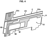
- FIG 4 illustrates the arrangement of antenna A and coupler C.
- the grounding points of the antenna are opposite the grounding points of the coupler C which are those of the coaxial connector.
- the branch 104 of the first pattern M1 connected to the entry point of the antenna A is opposite the branch 204 connecting the metallic zone 203 of the coupler C to the output point S of the coupler C.
- the printed parts are of course opposite each other.
- the radio path is identical whether antenna A is alone or with coupler C.
- the device described above can be used advantageously as an intelligent water meter, particularly when the location of the meter does not allow a good radio link (meter in the basement for example). In this case, it is essential to be able to transfer the radio function to an external antenna judiciously located so as to receive the radio signal.
- the measurement of the reflection parameter S11 covers the expected bands: LTE 20 and 8.
- the transmission losses measured S21 are acceptable (around 3dB).
Landscapes
- Physics & Mathematics (AREA)
- Fluid Mechanics (AREA)
- General Physics & Mathematics (AREA)
- Electromagnetism (AREA)
- Engineering & Computer Science (AREA)
- Computer Networks & Wireless Communication (AREA)
- Support Of Aerials (AREA)
- Details Of Aerials (AREA)
- Transceivers (AREA)
Abstract
un substrat (100),
un point (E) d'alimentation de l'antenne et un premier point (GND#1) de mise à la masse destiné à être relié à un plan de masse ;
un motif (101) antennaire métallique imprimé sur une face (102) du substrat, le motif (101) antennaire formant une boucle ouverte depuis le point (E) d'alimentation vers le premier point (GND#1) de mise à la masse, la boucle définissant en son centre une zone (103) non métallique ;
l'antenne (A) étant adaptée pour fonctionner seule pour rayonner un signal radio ou en association avec un coupleur (C) disposé en face et à distance de l'antenne (A) de manière à récupérer le signal rayonné par l'antenne (A), le coupleur (C) comprenant une zone (203) métallique complémentaire à la zone (103) non métallique en face.
Description
- La présente invention concerne une antenne et un coupleur associé permettant de déporter, de manière passive, une fonction antennaire. Elle concerne également un dispositif communicant comprenant une telle antenne pouvant fonctionner avec un tel coupleur.
- Un dispositif radio comprend habituellement une antenne interne (souvent parfaitement intégrée au dispositif) et une connexion vers une antenne externe pour permettre de commuter d'une antenne à l'autre en fonction des conditions d'utilisation, par exemple quand les conditions de réception par l'antenne radio sont mauvaises.
- Pour ce faire, un tel dispositif comprend deux voies radios séparées, chaque voie étant reliée soit à l'antenne interne soit à la connexion vers l'antenne externe. Pour commuter d'une voie à l'autre, un commutateur radiofréquence ou mécanique est utilisé.
- L'utilisation de ces types de commutateur n'est pas satisfaisante.
- En effet, un commutateur radiofréquence nécessite un mécanisme de détection de la présence d'une connexion externe qui peut s'avérer couteuse, encombrante et nuisible pour les performances radio en rajoutant de l'atténuation. Le système de détection présente aussi une problématique de consommation (surtout important pour les dispositifs sous batterie).
- Également, l'intégration d'un élément non linéaire supplémentaire comme c'est le cas du commutateur radiofréquence est une possible cause d'émissions ou de bruits indésirables.
- L'utilisation d'un commutateur mécanique est volumineuse et couteuse et difficile à intégrer dans un circuit imprimé. Le principal inconvénient fonctionnel de cette solution est l'apparition d'un bagotement mécanique en cas de serrage défaillant de l'antenne ou du câble coaxial. De plus, le chemin radio doit obligatoirement passer par le commutateur ce qui entraine des atténuations supplémentaires dans les performances.
- Par ailleurs, les systèmes de détection ne sont pas très fiables et génèrent souvent une fausse mesure, ce qui mène à la perte immédiate de la communication.
- L'invention propose de pallier au moins un des inconvénients évoqués ci-dessus.
- A cet effet, l'invention propose, selon un premier aspect une antenne d'un dispositif communicant, comprenant un substrat, un point d'alimentation de l'antenne et un premier point de mise à la masse destiné à être relié à un plan de masse ; un motif antennaire métallique imprimé sur une face du substrat, le motif antennaire formant une boucle ouverte depuis le point d'alimentation vers le premier point de mise à la masse, la boucle définissant en son centre une zone non métallique ; l'antenne étant adaptée pour fonctionner seule pour rayonner un signal radio ou en association avec un coupleur disposé en face et à distance de l'antenne de manière à récupérer le signal rayonné par l'antenne, le coupleur comprenant une zone métallique complémentaire à la zone non métallique en face.
- L'invention, selon le premier aspect, est avantageusement complétée par les caractéristiques suivantes, prises seules ou en une quelconque de leur combinaison techniquement possible :
- le motif antennaire comprend depuis, le point d'alimentation, un premier motif monobloc métallique constitué de deux branches longitudinales à distance l'une de l'autre, une branche transversale reliant les deux branches longitudinales, une première branche longitudinale s'étendant depuis le point d'alimentation, une deuxième branche longitudinale s'étendant depuis la branche transversale parallèlement à la première branche, le motif antennaire comprenant un deuxième motif monobloc s'étendant depuis le premier point de mise à la masse et comprend une branche transversale parallèle et à distance de la branche transversale du premier motif monobloc, la branche transversale du deuxième motif monobloc se terminant à une distance proche de 1 à 3 mm de la deuxième branche longitudinale du premier motif sans le toucher.
- la zone non métallique est rectangulaire.
- l'antenne comprend un deuxième point de mise à la masse destiné à être relié à un plan de masse et comprend un troisième motif monobloc s'étendant depuis le deuxième point de mise à la masse.
- le premier motif, le deuxième motif et le troisième motif sont configurés pour fonctionner dans les bandes LTE 20 et 8.
- L'invention concerne, selon un deuxième aspect, un coupleur d'un dispositif communicant comprenant un substrat rectangulaire comprenant un motif de couplage imprimé sur une face, le motif de couplage comprenant une zone métallique complémentaire à une zone non métallique d'une antenne destinée à être en face et distance du coupleur de manière à ce que le coupleur récupère le signal rayonné par l'antenne.
- L'invention concerne, selon un troisième aspect un dispositif communicant comprenant un premier logement pour loger une antenne selon le premier aspect de l'invention et un deuxième logement pour loger un coupleur selon le deuxième aspect de l'invention, le premier logement et le deuxième logement étant configurés l'un par rapport à l'autre de manière ce que le l'antenne et le coupleur puissent être l'un en face de l'autre, la zone métallique du coupleur étant alors en face de la zone non métallique de l'antenne, le dispositif comprenant deux modes de fonctionnement : un premier mode de fonctionnement comprenant uniquement l'antenne pour rayonner un signal radio, un deuxième mode de fonctionnement comprenant l'antenne et le coupleur pour déporter un signal radio rayonné par l'antenne vers une antenne externe adaptée pour être connectée au coupleur.
- L'invention, selon le troisième aspect est avantageusement complétée par les caractéristiques suivantes, prises seules ou en une quelconque de leur combinaison techniquement possible :
- le deuxième logement est adapté pour maintenir le coupleur en face et à une distance comprise entre 1 et 3mm de l'antenne.
- le coupleur comprend un connecteur connecté au motif de couplage, le connecteur étant adapté à être connecté à une antenne externe au moyen d'un câble.
- l'antenne est noyée dans un capot et dans lequel le logement pour le coupleur est une rainure formée dans le capot, le coupleur étant amovible.
- Les avantages de l'invention sont multiples.
- Le coupleur et l'antenne ne sont pas en contact de sorte qu'il n'est pas nécessaire d'ajouter d'éléments de connexion supplémentaires. Ceci est particulièrement avantageux lorsque le dispositif communicant est un compteur d'eau intelligent où l'étanchéité est recherchée pour être conforme à la protection IP67.
- L'antenne interne se comporte donc comme une antenne classique lorsqu'elle est utilisée seule et permet le déport du signal en le transmettant au coupleur lorsque celui-ci est positionné en face de l'antenne ceci sans avoir à changer de chemin radio. La présence d'un coupleur à proximité de l'antenne force cette dernière à fonctionner comme un coupleur. Ainsi, le signal utile n'est plus rayonné directement par l'antenne mais transmis à une antenne externe déportée par l'intermédiaire du coupleur adjacent.
- Le coupleur et l'antenne ne sont pas en contact direct ce qui permet une isolation électrique entre les deux (utile dans le cas des compteurs électrique). Par ailleurs, le passage d'un mode de fonctionnement à l'autre ne nécessite aucune action électronique ou logiciel : la présence du coupleur permet de passer du mode de rayonnement antenne interne au mode couplage vers antenne externe.
- D'autres caractéristiques, buts et avantages de l'invention ressortiront de la description qui suit, qui est purement illustrative et non limitative, et qui doit être lue en regard des dessins annexés sur lesquels :
- la
figure 1a , lafigure 1b , lafigure1c , lafigure 1d et lafigure 1e illustrent plusieurs vues d'un dispositif communicant conforme à l'invention ; - la
figure 2 illustre une antenne conforme à l'invention ; - la
figure 3 illustre un coupleur conforme à l'invention ; - la
figure 4 illustre une vue de côté du dispositif communicant conforme à l'invention comprenant à la fois une antenne et un coupleur en face. - Sur l'ensemble des figures les éléments similaires portent des références identiques.
- Les
figures 1a, 1b, 1c ,1d, 1e illustrent plusieurs vues d'un dispositif D communicant comprenant une enceinte 1 logeant une carte 6 électronique ainsi que des composants électroniques (non visibles). L'enceinte 1 comporte un fond 11 et quatre parois 12 (deux sont visibles sur les figures) s'élevant depuis le fond 11. L'enceinte 1 définie un volume qui loge l'électronique. Une antenne A dite antenne interne est connectée à la carte 6 électronique et permet au dispositif D communicant d'émettre et recevoir des signaux. Comme on le verra par la suite, l'antenne A interne se présente sous la forme d'une plaque de forme générale rectangulaire. La carte 6 électronique assure tous les traitements radios nécessaires à la communication. - Un tel dispositif D communicant est par exemple un compteur d'eau pour lequel des relevées périodiques doivent être effectués à distance. De manière plus générale, on note que l'invention s'applique à tous dispositifs communicants.
- Pour favoriser la communication, l'antenne A interne fait saillie de l'enceinte 1 et est protégée par un capot 2 comprenant un logement pour l'antenne A interne et qui obture l'enceinte 1. Le capot 2 comporte une paroi principale 21 qui permet de fermer l'enceinte 1 en étant parallèle au fond 11 et une paroi 22 secondaire en saillie de la paroi 21 principale dans laquelle est logée à l'intérieur l'antenne A interne. Ainsi la paroi 22 secondaire présente une épaisseur suffisante pour loger l'antenne 1 interne.
- Comme illustré sur les
figures 1b ,1d et 1d , le dispositif communicant avec le capot 2 et l'enceinte 1 assemblés ne permet pas de voir l'antenne A interne. - De manière complémentaire un couvercle 5 se clipse sur le capot 2 pour protéger le tout comme illustré sur la
figure 1a . - L'enceinte 1, le capot 2, le couvercle 5 sont de préférence en plastique. En fonction de l'application, l'enceinte est remplie d'un gel protecteur étanche pour protéger l'électronique qui y est logée. En effet, le dispositif communicant peut être utilisé comme compteur d'eau intelligent et doit être étanche.
- Le capot 2 comporte en face et à distance de la paroi 22 secondaire, une paroi 23 auxiliaire. La paroi 22 secondaire et la paroi 23 auxiliaire définissent ensemble une rainure 24 qui permet de recevoir un coupleur C qui se présente sous la forme d'une plaque de forme générale rectangulaire. Un tel coupleur C est amovible et se place dans la rainure 24 en face de l'antenne A interne. La rainure 24 comprend également des éléments de maintien du coupleur C en face de l'antenne A interne. Le coupleur C est muni, par exemple d'un connecteur 3 coaxial auquel un câble 4 coaxial peut être connecté. A l'extrémité du câble est coaxial est connectée une antenne externe Aext. Pour connecter le coupleur à l'antenne externe Aext il convient de prévoir un connecteur adapté 50 Ohms.
- Le rainure 24 et la paroi secondaire 22 présentes des dimensions qui permettent de positionner le coupleur C à une distance de l'antenne A comprise entre 1 et 5 mm, de préférence 2 mm. En d'autres termes, il s'agit de positionner le coupleur C le plus proche possible de l'antenne A pour favoriser le couplage C du signal rayonné par l'antenne A.
- La rainure 24 est en outre conformée pour permettre de positionner précisément le coupleur C en face de l'antenne A pour que le couplage soit optimal avec le moins de perte possible.
- En outre, le coupleur C est un composant passif qui n'est pas en contact électrique avec l'antenne A ce qui permet d'éviter de compromettre le dispositif D communicant. En effet, pour positionner le coupleur C il s'agit simplement de le placer dans la fente 24 prévue à cet effet. Il n'est donc pas nécessaire de le démonter ou d'entrer en contact avec l'électronique à l'intérieur. L'indice de protection, noté IP n'est donc par altéré.
- Un tel dispositif communicant présente deux modes de fonctionnement.
- Un premier mode comprenant uniquement l'antenne A qui permet de rayonner un signal radio (voir les
figures 1b et 1c ) ou de recevoir un signal radio. - Un deuxième mode comprenant l'antenne A et le coupleur C de manière à déporter le signal rayonné par l'antenne A vers l'antenne externe (voir les
figures 1d et 1e ). L'émission/réception du signal radio se faisant par l'antenne externe Aext. - De cette manière il est possible de positionner le dispositif communicant n'importe où, l'émission/réception se faisant à distance du dispositif communicant.
- Le passage d'un mode à l'autre ne nécessite aucune action logicielle ni la présence d'un commutateur. Il s'agit seulement de positionner le coupleur C dans la rainure 24 prévue à cet effet.
- De manière avantageuse, le dispositif communicant est tel qu'il fonctionne de préférence dans les bandes LTE 20 et 8 (c'est-à-dire dans les bandes de 800 MHz et 900 MHz). Ces bandes sont notamment utilisés dans le domaine des compteurs intelligent par exemple pour des compteurs d'eau. De manière alternative, c'est la définition du coupleur C et de l'antenne A interne qui permet de régler les bandes de fonctionnement.
- La
figure 2 illustre en détail un mode de réalisation de l'antenne A adaptée à être intégré au dispositif D communicant précédemment décrit. - L'antenne A est une antenne imprimée comprenant un substrat 100 en matériau diélectrique comprenant un point E d'alimentation de l'antenne A et un premier point GND#1 de mise à la masse relié à un plan de masse (non représenté) de l'antenne A. Le point E d'alimentation est le point d'entrée du signal radio que l'antenne A doit rayonner (dans le sens d'émission). Le substrat 100 est de forme générale rectangulaire et s'étend selon un direction transversale X et longitudinale Z.
- Sur une face 102 du substrat 100 est imprimé un motif 101 antennaire métallique. Le motif 101 antennaire métallique est par exemple du cuivre et est imprimé selon des techniques bien connues de l'homme du métier.
- Le motif 101 antennaire métallique forme une boucle ouverte depuis le point E d'alimentation vers le premier point GND#1 de mise à la masse, la boucle définissant en son centre une zone 103 non métallique. Le fait que le motif 101 antennaire forme une boucle ouverte (en fait presque fermée) permet le rayonnement du signal radio. En outre, le motif 101 étant une boucle presque fermée permet à l'antenne de se coupler au coupleur C en face.
- La zone 102 non métallique est de préférence rectangulaire. D'autres formes sont envisageables.
- L'antenne A est adaptée pour fonctionner, en émission, seule pour rayonner un signal radio ou en association avec un coupleur C disposé en face et à distance de l'antenne A de manière à récupérer le signal rayonné par l'antenne A, le coupleur C comprenant, à ce titre, une zone 203 métallique complémentaire à la zone 103 non métallique en face.
- Le motif 101 antennaire présente une forme qui est adaptée à l'application envisagée en termes de fréquences d'utilisation.
- Selon le mode de réalisation illustré sur la
figure 2 , le motif 101 antennaire comprend depuis, le point E d'alimentation un premier motif M1 monobloc métallique constitué de deux branches 104, 105 longitudinales à distance l'une de l'autre, une branche 106 transversale reliant les deux branches 104, 105 longitudinales, une première branche 104 longitudinale s'étendant depuis le point E d'alimentation, une deuxième branche 105 longitudinale s'étendant depuis la branche 106 transversale parallèlement à la première branche 104. Ce premier motif M1 est principalement en forme de U. Les différentes branches qui constituent le premier motif M1 présentent des épaisseurs variées. - Une quatrième branche 114 est ici présente dans le prolongement de la branche transversale 106 du U.
- Un deuxième motif M2 métallique monobloc s'étend depuis le premier point GND#1 de mise à la masse connecté à un plan de masse. Il comprend une branche 107 longitudinale qui s'étend depuis le premier point GND#1 suivie d'une branche 108 transversale parallèle et à distance de la branche 105 transversale du premier motif monobloc M1, la branche 107 transversale du deuxième motif (M2) monobloc se terminant à une distance proche de 1 à 3 mm de la deuxième branche 105 longitudinale du premier motif M1 sans le toucher. En d'autres termes, le deuxième motif M2 permet de former avec le premier motif M1 la boucle ouverte et sont adaptés en fonction du rayonnement souhaité pour l'antenne A.
- Un troisième motif M3 métallique s'étend depuis un deuxième point GND#2 de mise à la masse de l'antenne A et permet de régler l'adaptation de l'antenne A : une branche longitudinale 109 s'étend depuis le deuxième point GND#2 de mise à la masse suivie d'une branche 110 transversale qui est parallèle la branche 106 transversale du premier motif M1.
- La
figure 3 illustre en détail un mode de réalisation d'un coupleur C adapté à être intégré au dispositif D communicant précédemment décrit. - Le coupleur C comprend un substrat 200 en matériau diélectrique et comprenant un motif 201 de couplage imprimé sur une face 202, le motif 201 de couplage. Le motif 201 de couplage comprend une zone 203 métallique complémentaire à la zone 103 non métallique de l'antenne A destinée à être en face et distance du coupleur C de manière à ce que le coupleur C récupère le signal rayonné par l'antenne A. La zone 203 métallique est prolongée d'une branche longitudinale qui est reliée par un connecteur 300 à une sortie S du coupleur C. Le connecteur 300 est adapté 50 Ohm.
- Le substrat 200 présente une partie 200a rectangulaire depuis laquelle s'étend une patte 200b qui permet de connecter un connecteur 3 coaxial au coupleur C et notamment à la sortie S du coupleur C. Le connecteur 3 est placée sur une face opposée à celle sur laquelle est imprimée le motif 201 de couplage. Le connecteur 3 est lui connecté à un câble coaxial connecté à l'antenne Aext externe.
- Le motif 201 de couplage présente donc majoritairement une zone 203 métallique rectangulaire depuis laquelle s'étendent des branches 204, 205, 206, 207, 208, 209 qui permettent de régler l'adaptation du coupleur C et d'assurer les connexions du coupleur C au connecteur 3. La zone métallique 203 est donc entourée d'une boucle. Des branches longitudinales 205, 209 sont imprimées sur le substrat pour être en face des branches 107, 109 de l'antenne A qui sont reliées aux points de mise à la masse GND#1, GND#2. Les branches 205, 209 permettent aussi de capter le signal provenant de l'antenne A et améliorent ainsi le couplage.
- La zone 202 métallique rectangulaire lorsqu'elle est en face de la zone non métallique de l'antenne A permet de récupérer le signal rayonné par l'antenne A et de l'amener vers le sortie S du coupleur (en émission).
- La forme de la zone métallique est conditionnée par la zone métallique de l'antenne A qui doit être en face.
- La
figure 4 illustre l'agencement de l'antenne A et du coupleur C. Lorsque le coupleur C est positionné en face de l'antenne A, les points de mise à la masse de l'antenne sont en face des points de mise à la masse du coupleur C qui sont ceux du connecteur coaxial. Également, la branche 104 du premier motif M1 connecté au point d'entrée de l'antenne A est en face de la branche 204 connectant la zone 203 métallique du coupleur C au point de sortie S du coupleur C. En outre, les parties imprimées sont bien entendu l'une en face de l'autre. - Ainsi, le chemin radio est identique que l'antenne A soit seule ou avec le coupleur C.
- Le dispositif ci-dessus décrit s'utilise avantageusement comme un compteur d'eau intelligent et notamment lorsque la localisation du compteur ne permet pas une bonne liaison radio (compteur en sous-sol par exemple). Dans ce cas, il est primordial de pouvoir déporter la fonction radio vers une antenne externe judicieusement localisée de manière à recevoir le signal radio.
- En outre, un dispositif conforme à l'invention a été réalisé et testé. En monde avec l'antenne A seule, la mesure du paramètre de réflexion S11 couvre bien les bandes attendues : LTE 20 et 8. Lorsque l'antenne A fonctionne avec le coupleur C les pertes en transmission mesurées S21 sont acceptables (environ 3dB).
Claims (8)
- Dispositif (30) communicant comprenant un premier logement (22) pour loger une antenne et un deuxième logement (24) pour loger un coupleur (C),l'antenne comprenant :un substrat (100),un point (E) d'alimentation de l'antenne et un premier point (GND#1) de mise à la masse destiné à être relié à un plan de masse ;un motif (101) antennaire métallique imprimé sur une face (102) du substrat, le motif (101) antennaire formant une boucle ouverte depuis le point (E) d'alimentation vers le premier point (GND#1) de mise à la masse, la boucle définissant en son centre une zone (103) non métallique ;l'antenne (A) étant adaptée pour fonctionner seule, selon un premier mode, pour rayonner un signal radio et un second mode en association avec un coupleur (C) disposé en face et à distance de l'antenne (A).le coupleur (C) comprenant un substrat (200) rectangulaire comprenant un motif (201) de couplage imprimé sur une face, le motif (201) de couplage comprenant une zone (203) métallique complémentaire à une zone (103) non métallique de l'antenne (A) destinée à être en face et distance du coupleur (C) de manière à ce que le coupleur (C) récupère le signal rayonné par l'antenne (A),le premier logement et le deuxième logement étant configurés l'un par rapport à l'autre de manière ce que le l'antenne et le coupleur puissent être l'un en face de l'autre, la zone (203) métallique du coupleur étant alors en face de la zone (103) non métallique de l'antenne (A), le dispositif comprenant deux modes de fonctionnement :un premier mode de fonctionnement comprenant uniquement l'antenne (1) pour rayonner un signal radio,un deuxième mode de fonctionnement comprenant l'antenne (A) et le coupleur (C) de manière à récupérer le signal rayonné par l'antenne (A) pour déporter un signal radio rayonné par l'antenne (A) vers une antenne externe adaptée pour être connectée au coupleur (C).
- Dispositif selon la revendication 1, dans lequel le motif (101) antennaire comprend depuis, le point (E) d'alimentation, un premier motif (M1) monobloc métallique constitué de deux branches (104, 105) longitudinales à distance l'une de l'autre, une branche (106) transversale reliant les deux branches (104, 105) longitudinales, une première branche (104) longitudinale s'étendant depuis le point (E) d'alimentation, une deuxième branche (105) longitudinale s'étendant depuis la branche (106) transversale parallèlement à la première branche (104), le motif (101) antennaire comprenant un deuxième motif monobloc (M2) s'étendant depuis le premier point (GND#1) de mise à la masse et comprend une branche (107) transversale parallèle et à distance de la branche (105) transversale du premier motif monobloc (M1), la branche (107) transversale du deuxième motif (M2) monobloc se terminant à une distance proche de 1 à 3 mm de la deuxième branche (105) longitudinale du premier motif (M1) sans le toucher.
- Dispositif selon la revendication 2, dans lequel l'antenne comprend un deuxième point (GND#2) de mise à la masse destiné à être relié à un plan de masse et comprend un troisième motif (M3) monobloc s'étendant depuis le deuxième point (GND#2) de mise à la masse.
- Dispositif selon la revendication 3, dans lequel le premier motif (M1), le deuxième motif (M2) et le troisième motif (M3) de l'antenne sont configurés pour fonctionner dans les bandes LTE 20 et 8.
- Dispositif selon l'une quelconque des revendications 1 à 4, dans laquelle la zone (103) non métallique de l'antenne est rectangulaire.
- Dispositif selon la revendication 5, dans lequel le deuxième logement est adapté pour maintenir le coupleur (C) en face et à une distance comprise entre 1 et 3mm de l'antenne (A).
- Dispositif selon l'une des revendications 1 à 6, dans lequel le coupleur (C) comprend un connecteur (3) connecté au motif de couplage (201), le connecteur (3) étant adapté à être connecté à une antenne externe (Aext) au moyen d'un câble (4).
- Dispositif selon l'une des revendications 1 à 7, dans lequel l'antenne (A) est noyée dans un capot et dans lequel le logement pour le coupleur est une rainure (24) formée dans le capot, le coupleur étant amovible.
Applications Claiming Priority (1)
| Application Number | Priority Date | Filing Date | Title |
|---|---|---|---|
| FR2213657A FR3143887A1 (fr) | 2022-12-16 | 2022-12-16 | Antenne et coupleur associé pour réaliser un déport d’une fonction antennaire ainsi que dispositif communicant correspondant |
Publications (2)
| Publication Number | Publication Date |
|---|---|
| EP4386990A1 true EP4386990A1 (fr) | 2024-06-19 |
| EP4386990B1 EP4386990B1 (fr) | 2025-01-22 |
Family
ID=85792379
Family Applications (1)
| Application Number | Title | Priority Date | Filing Date |
|---|---|---|---|
| EP23217008.4A Active EP4386990B1 (fr) | 2022-12-16 | 2023-12-15 | Antenne et coupleur associé pour réaliser un déport d'une fonction antennaire ainsi que dispositif communicant correspondant |
Country Status (5)
| Country | Link |
|---|---|
| US (1) | US20240204407A1 (fr) |
| EP (1) | EP4386990B1 (fr) |
| CN (1) | CN118213747B (fr) |
| ES (1) | ES3024088T3 (fr) |
| FR (1) | FR3143887A1 (fr) |
Citations (5)
| Publication number | Priority date | Publication date | Assignee | Title |
|---|---|---|---|---|
| US20020154066A1 (en) * | 2001-03-07 | 2002-10-24 | Zsolt Barna | Antenna coupling device |
| US20040212545A1 (en) * | 2002-09-25 | 2004-10-28 | Li Ronglin | Multi-band broadband planar antennas |
| US20130050036A1 (en) * | 2011-08-30 | 2013-02-28 | Ippei Kashiwagi | Antenna device and electronic apparatus including antenna device |
| DE102012112266B3 (de) * | 2012-12-14 | 2014-04-30 | Bury Sp.Z.O.O. | Koppelantennenanordnung und Aufnahmehalter einer Freisprecheinrichtung |
| US20200053436A1 (en) * | 2018-08-10 | 2020-02-13 | Arad Measuring Technologies Ltd. | Electromagnetic Meter Coupling |
Family Cites Families (3)
| Publication number | Priority date | Publication date | Assignee | Title |
|---|---|---|---|---|
| US7388543B2 (en) * | 2005-11-15 | 2008-06-17 | Sony Ericsson Mobile Communications Ab | Multi-frequency band antenna device for radio communication terminal having wide high-band bandwidth |
| TWI360917B (en) * | 2008-06-10 | 2012-03-21 | Univ Nat Sun Yat Sen | A multiband loop antenna |
| CN106207441A (zh) * | 2016-06-29 | 2016-12-07 | 青岛海信移动通信技术股份有限公司 | 一种移动终端的nfc天线和移动终端 |
-
2022
- 2022-12-16 FR FR2213657A patent/FR3143887A1/fr not_active Ceased
-
2023
- 2023-12-15 ES ES23217008T patent/ES3024088T3/es active Active
- 2023-12-15 CN CN202311728932.3A patent/CN118213747B/zh active Active
- 2023-12-15 US US18/541,310 patent/US20240204407A1/en active Pending
- 2023-12-15 EP EP23217008.4A patent/EP4386990B1/fr active Active
Patent Citations (5)
| Publication number | Priority date | Publication date | Assignee | Title |
|---|---|---|---|---|
| US20020154066A1 (en) * | 2001-03-07 | 2002-10-24 | Zsolt Barna | Antenna coupling device |
| US20040212545A1 (en) * | 2002-09-25 | 2004-10-28 | Li Ronglin | Multi-band broadband planar antennas |
| US20130050036A1 (en) * | 2011-08-30 | 2013-02-28 | Ippei Kashiwagi | Antenna device and electronic apparatus including antenna device |
| DE102012112266B3 (de) * | 2012-12-14 | 2014-04-30 | Bury Sp.Z.O.O. | Koppelantennenanordnung und Aufnahmehalter einer Freisprecheinrichtung |
| US20200053436A1 (en) * | 2018-08-10 | 2020-02-13 | Arad Measuring Technologies Ltd. | Electromagnetic Meter Coupling |
Also Published As
| Publication number | Publication date |
|---|---|
| ES3024088T3 (en) | 2025-06-03 |
| CN118213747A (zh) | 2024-06-18 |
| US20240204407A1 (en) | 2024-06-20 |
| CN118213747B (zh) | 2025-12-09 |
| EP4386990B1 (fr) | 2025-01-22 |
| FR3143887A1 (fr) | 2024-06-21 |
Similar Documents
| Publication | Publication Date | Title |
|---|---|---|
| EP1172885B1 (fr) | Antenne à couche conductrice et dispositif de transmission bi-bande incluant cette antenne. | |
| EP0954055B1 (fr) | Antenne bifréquence pour la radiocommunication réalisée selon la technique des microrubans | |
| EP0995234A1 (fr) | Antenne a plaque | |
| FR2860927A1 (fr) | Antenne interne de faible volume | |
| FR2825517A1 (fr) | Antenne a plaque | |
| FR2888675A1 (fr) | Systeme d'antenne a diversite d'ordre 2 et carte pour appareil de communication sans fil munie d'un tel systeme | |
| FR2853996A1 (fr) | Systeme d'antennes | |
| FR2819346A1 (fr) | Antenne planaire et dispositif de transmission bi-bande incluant cette antenne | |
| EP2404348B1 (fr) | Procédé de réalisation d'une antenne fonctionnant dans une bande de fréquences donnée a partir d'une antenne bi-bande | |
| EP0023873A1 (fr) | Limiteur passif de puissance à semi-conducteurs réalisé sur des lignes à structure plane, et circuit hyperfréquence utilisant un tel limiteur | |
| EP4386990B1 (fr) | Antenne et coupleur associé pour réaliser un déport d'une fonction antennaire ainsi que dispositif communicant correspondant | |
| EP0243888B1 (fr) | Dispositif à joint tournant hyperfréquence | |
| FR2740912A1 (fr) | Perfectionnements concernant des connecteurs coaxiaux | |
| FR2733348A1 (fr) | Connecteur interrupteur ou inverseur coaxial miniature a lames de contact actives | |
| EP3512057A1 (fr) | Appareil électrique communiquant sans fil et armoire électrique comprenant cet appareil électrique | |
| FR2980932A1 (fr) | Dispositif pour emettre ou recevoir des signaux radioelectriques , notamment pour vehicule automobile | |
| EP3964898B1 (fr) | Dispositif d'antenne pour piece d'horlogerie | |
| EP4167378A1 (fr) | Dispositif d'antennes radiofrequences isolees | |
| CA2294578A1 (fr) | Antenne a efficacite de liaison amelioree | |
| EP3968102B1 (fr) | Dispositif d'antenne | |
| EP3641058A1 (fr) | Antenne multibandes commutée et dispositif radiofréquence comprenant une telle antenne | |
| EP3605734A1 (fr) | Dispositif d'antenne comportant au moins deux antennes à même substrat de raccordement électrique | |
| FR2733369A1 (fr) | Connecteur interrupteur ou inverseur coaxial miniature a plongeur et lames de contact passives | |
| FR2778499A1 (fr) | Antenne a plaque | |
| EP1249889B1 (fr) | Filtre hyperfréquence à résonateur diélectrique |
Legal Events
| Date | Code | Title | Description |
|---|---|---|---|
| PUAI | Public reference made under article 153(3) epc to a published international application that has entered the european phase |
Free format text: ORIGINAL CODE: 0009012 |
|
| STAA | Information on the status of an ep patent application or granted ep patent |
Free format text: STATUS: EXAMINATION IS IN PROGRESS |
|
| 17P | Request for examination filed |
Effective date: 20231215 |
|
| AK | Designated contracting states |
Kind code of ref document: A1 Designated state(s): AL AT BE BG CH CY CZ DE DK EE ES FI FR GB GR HR HU IE IS IT LI LT LU LV MC ME MK MT NL NO PL PT RO RS SE SI SK SM TR |
|
| RIC1 | Information provided on ipc code assigned before grant |
Ipc: G01D 4/00 20060101ALN20240705BHEP Ipc: G01F 15/06 20220101ALI20240705BHEP Ipc: G01F 15/14 20060101ALI20240705BHEP Ipc: H01Q 3/24 20060101ALI20240705BHEP Ipc: H01Q 1/22 20060101ALI20240705BHEP Ipc: H01Q 5/371 20150101ALI20240705BHEP Ipc: H01Q 9/42 20060101AFI20240705BHEP |
|
| GRAP | Despatch of communication of intention to grant a patent |
Free format text: ORIGINAL CODE: EPIDOSNIGR1 |
|
| STAA | Information on the status of an ep patent application or granted ep patent |
Free format text: STATUS: GRANT OF PATENT IS INTENDED |
|
| RIC1 | Information provided on ipc code assigned before grant |
Ipc: G01D 4/00 20060101ALN20240828BHEP Ipc: G01F 15/06 20220101ALI20240828BHEP Ipc: G01F 15/14 20060101ALI20240828BHEP Ipc: H01Q 3/24 20060101ALI20240828BHEP Ipc: H01Q 1/22 20060101ALI20240828BHEP Ipc: H01Q 5/371 20150101ALI20240828BHEP Ipc: H01Q 9/42 20060101AFI20240828BHEP |
|
| INTG | Intention to grant announced |
Effective date: 20240905 |
|
| GRAS | Grant fee paid |
Free format text: ORIGINAL CODE: EPIDOSNIGR3 |
|
| GRAA | (expected) grant |
Free format text: ORIGINAL CODE: 0009210 |
|
| STAA | Information on the status of an ep patent application or granted ep patent |
Free format text: STATUS: THE PATENT HAS BEEN GRANTED |
|
| AK | Designated contracting states |
Kind code of ref document: B1 Designated state(s): AL AT BE BG CH CY CZ DE DK EE ES FI FR GB GR HR HU IE IS IT LI LT LU LV MC ME MK MT NL NO PL PT RO RS SE SI SK SM TR |
|
| REG | Reference to a national code |
Ref country code: GB Ref legal event code: FG4D Free format text: NOT ENGLISH |
|
| REG | Reference to a national code |
Ref country code: CH Ref legal event code: EP |
|
| REG | Reference to a national code |
Ref country code: IE Ref legal event code: FG4D Free format text: LANGUAGE OF EP DOCUMENT: FRENCH |
|
| REG | Reference to a national code |
Ref country code: DE Ref legal event code: R096 Ref document number: 602023001779 Country of ref document: DE |
|
| REG | Reference to a national code |
Ref country code: NL Ref legal event code: MP Effective date: 20250122 |
|
| REG | Reference to a national code |
Ref country code: ES Ref legal event code: FG2A Ref document number: 3024088 Country of ref document: ES Kind code of ref document: T3 Effective date: 20250603 |
|
| PG25 | Lapsed in a contracting state [announced via postgrant information from national office to epo] |
Ref country code: NL Free format text: LAPSE BECAUSE OF FAILURE TO SUBMIT A TRANSLATION OF THE DESCRIPTION OR TO PAY THE FEE WITHIN THE PRESCRIBED TIME-LIMIT Effective date: 20250122 |
|
| PG25 | Lapsed in a contracting state [announced via postgrant information from national office to epo] |
Ref country code: RS Free format text: LAPSE BECAUSE OF FAILURE TO SUBMIT A TRANSLATION OF THE DESCRIPTION OR TO PAY THE FEE WITHIN THE PRESCRIBED TIME-LIMIT Effective date: 20250422 |
|
| PG25 | Lapsed in a contracting state [announced via postgrant information from national office to epo] |
Ref country code: FI Free format text: LAPSE BECAUSE OF FAILURE TO SUBMIT A TRANSLATION OF THE DESCRIPTION OR TO PAY THE FEE WITHIN THE PRESCRIBED TIME-LIMIT Effective date: 20250122 |
|
| PG25 | Lapsed in a contracting state [announced via postgrant information from national office to epo] |
Ref country code: PL Free format text: LAPSE BECAUSE OF FAILURE TO SUBMIT A TRANSLATION OF THE DESCRIPTION OR TO PAY THE FEE WITHIN THE PRESCRIBED TIME-LIMIT Effective date: 20250122 |
|
| REG | Reference to a national code |
Ref country code: LT Ref legal event code: MG9D |
|
| PG25 | Lapsed in a contracting state [announced via postgrant information from national office to epo] |
Ref country code: IS Free format text: LAPSE BECAUSE OF FAILURE TO SUBMIT A TRANSLATION OF THE DESCRIPTION OR TO PAY THE FEE WITHIN THE PRESCRIBED TIME-LIMIT Effective date: 20250522 Ref country code: NO Free format text: LAPSE BECAUSE OF FAILURE TO SUBMIT A TRANSLATION OF THE DESCRIPTION OR TO PAY THE FEE WITHIN THE PRESCRIBED TIME-LIMIT Effective date: 20250422 |
|
| REG | Reference to a national code |
Ref country code: AT Ref legal event code: MK05 Ref document number: 1762177 Country of ref document: AT Kind code of ref document: T Effective date: 20250122 |
|
| PG25 | Lapsed in a contracting state [announced via postgrant information from national office to epo] |
Ref country code: HR Free format text: LAPSE BECAUSE OF FAILURE TO SUBMIT A TRANSLATION OF THE DESCRIPTION OR TO PAY THE FEE WITHIN THE PRESCRIBED TIME-LIMIT Effective date: 20250122 |
|
| PG25 | Lapsed in a contracting state [announced via postgrant information from national office to epo] |
Ref country code: PT Free format text: LAPSE BECAUSE OF FAILURE TO SUBMIT A TRANSLATION OF THE DESCRIPTION OR TO PAY THE FEE WITHIN THE PRESCRIBED TIME-LIMIT Effective date: 20250522 Ref country code: LV Free format text: LAPSE BECAUSE OF FAILURE TO SUBMIT A TRANSLATION OF THE DESCRIPTION OR TO PAY THE FEE WITHIN THE PRESCRIBED TIME-LIMIT Effective date: 20250122 |
|
| PG25 | Lapsed in a contracting state [announced via postgrant information from national office to epo] |
Ref country code: BG Free format text: LAPSE BECAUSE OF FAILURE TO SUBMIT A TRANSLATION OF THE DESCRIPTION OR TO PAY THE FEE WITHIN THE PRESCRIBED TIME-LIMIT Effective date: 20250122 Ref country code: GR Free format text: LAPSE BECAUSE OF FAILURE TO SUBMIT A TRANSLATION OF THE DESCRIPTION OR TO PAY THE FEE WITHIN THE PRESCRIBED TIME-LIMIT Effective date: 20250423 |
|
| PG25 | Lapsed in a contracting state [announced via postgrant information from national office to epo] |
Ref country code: AT Free format text: LAPSE BECAUSE OF FAILURE TO SUBMIT A TRANSLATION OF THE DESCRIPTION OR TO PAY THE FEE WITHIN THE PRESCRIBED TIME-LIMIT Effective date: 20250122 |
|
| PG25 | Lapsed in a contracting state [announced via postgrant information from national office to epo] |
Ref country code: SE Free format text: LAPSE BECAUSE OF FAILURE TO SUBMIT A TRANSLATION OF THE DESCRIPTION OR TO PAY THE FEE WITHIN THE PRESCRIBED TIME-LIMIT Effective date: 20250122 |
|
| PG25 | Lapsed in a contracting state [announced via postgrant information from national office to epo] |
Ref country code: SM Free format text: LAPSE BECAUSE OF FAILURE TO SUBMIT A TRANSLATION OF THE DESCRIPTION OR TO PAY THE FEE WITHIN THE PRESCRIBED TIME-LIMIT Effective date: 20250122 |
|
| PG25 | Lapsed in a contracting state [announced via postgrant information from national office to epo] |
Ref country code: DK Free format text: LAPSE BECAUSE OF FAILURE TO SUBMIT A TRANSLATION OF THE DESCRIPTION OR TO PAY THE FEE WITHIN THE PRESCRIBED TIME-LIMIT Effective date: 20250122 |
|
| PG25 | Lapsed in a contracting state [announced via postgrant information from national office to epo] |
Ref country code: EE Free format text: LAPSE BECAUSE OF FAILURE TO SUBMIT A TRANSLATION OF THE DESCRIPTION OR TO PAY THE FEE WITHIN THE PRESCRIBED TIME-LIMIT Effective date: 20250122 Ref country code: CZ Free format text: LAPSE BECAUSE OF FAILURE TO SUBMIT A TRANSLATION OF THE DESCRIPTION OR TO PAY THE FEE WITHIN THE PRESCRIBED TIME-LIMIT Effective date: 20250122 |
|
| REG | Reference to a national code |
Ref country code: DE Ref legal event code: R097 Ref document number: 602023001779 Country of ref document: DE |
|
| PG25 | Lapsed in a contracting state [announced via postgrant information from national office to epo] |
Ref country code: RO Free format text: LAPSE BECAUSE OF FAILURE TO SUBMIT A TRANSLATION OF THE DESCRIPTION OR TO PAY THE FEE WITHIN THE PRESCRIBED TIME-LIMIT Effective date: 20250122 |
|
| PG25 | Lapsed in a contracting state [announced via postgrant information from national office to epo] |
Ref country code: SK Free format text: LAPSE BECAUSE OF FAILURE TO SUBMIT A TRANSLATION OF THE DESCRIPTION OR TO PAY THE FEE WITHIN THE PRESCRIBED TIME-LIMIT Effective date: 20250122 |
|
| PLBE | No opposition filed within time limit |
Free format text: ORIGINAL CODE: 0009261 |
|
| STAA | Information on the status of an ep patent application or granted ep patent |
Free format text: STATUS: NO OPPOSITION FILED WITHIN TIME LIMIT |
|
| 26N | No opposition filed |
Effective date: 20251023 |
|
| PGFP | Annual fee paid to national office [announced via postgrant information from national office to epo] |
Ref country code: FR Payment date: 20251120 Year of fee payment: 3 |
|
| PGFP | Annual fee paid to national office [announced via postgrant information from national office to epo] |
Ref country code: BE Payment date: 20251119 Year of fee payment: 3 |
|
| PGFP | Annual fee paid to national office [announced via postgrant information from national office to epo] |
Ref country code: ES Payment date: 20260102 Year of fee payment: 3 |
|
| PGFP | Annual fee paid to national office [announced via postgrant information from national office to epo] |
Ref country code: IT Payment date: 20251231 Year of fee payment: 3 |