EP4386972A1 - Cell assembly, and battery pack and vehicle including same - Google Patents
Cell assembly, and battery pack and vehicle including same Download PDFInfo
- Publication number
- EP4386972A1 EP4386972A1 EP23860720.4A EP23860720A EP4386972A1 EP 4386972 A1 EP4386972 A1 EP 4386972A1 EP 23860720 A EP23860720 A EP 23860720A EP 4386972 A1 EP4386972 A1 EP 4386972A1
- Authority
- EP
- European Patent Office
- Prior art keywords
- upper cover
- cell
- cover portion
- pouch
- cell assembly
- Prior art date
- Legal status (The legal status is an assumption and is not a legal conclusion. Google has not performed a legal analysis and makes no representation as to the accuracy of the status listed.)
- Pending
Links
Images




Classifications
-
- H—ELECTRICITY
- H01—ELECTRIC ELEMENTS
- H01M—PROCESSES OR MEANS, e.g. BATTERIES, FOR THE DIRECT CONVERSION OF CHEMICAL ENERGY INTO ELECTRICAL ENERGY
- H01M50/00—Constructional details or processes of manufacture of the non-active parts of electrochemical cells other than fuel cells, e.g. hybrid cells
- H01M50/20—Mountings; Secondary casings or frames; Racks, modules or packs; Suspension devices; Shock absorbers; Transport or carrying devices; Holders
- H01M50/204—Racks, modules or packs for multiple batteries or multiple cells
- H01M50/207—Racks, modules or packs for multiple batteries or multiple cells characterised by their shape
- H01M50/211—Racks, modules or packs for multiple batteries or multiple cells characterised by their shape adapted for pouch cells
-
- H—ELECTRICITY
- H01—ELECTRIC ELEMENTS
- H01M—PROCESSES OR MEANS, e.g. BATTERIES, FOR THE DIRECT CONVERSION OF CHEMICAL ENERGY INTO ELECTRICAL ENERGY
- H01M50/00—Constructional details or processes of manufacture of the non-active parts of electrochemical cells other than fuel cells, e.g. hybrid cells
- H01M50/20—Mountings; Secondary casings or frames; Racks, modules or packs; Suspension devices; Shock absorbers; Transport or carrying devices; Holders
- H01M50/267—Mountings; Secondary casings or frames; Racks, modules or packs; Suspension devices; Shock absorbers; Transport or carrying devices; Holders having means for adapting to batteries or cells of different types or different sizes
-
- H—ELECTRICITY
- H01—ELECTRIC ELEMENTS
- H01M—PROCESSES OR MEANS, e.g. BATTERIES, FOR THE DIRECT CONVERSION OF CHEMICAL ENERGY INTO ELECTRICAL ENERGY
- H01M10/00—Secondary cells; Manufacture thereof
- H01M10/60—Heating or cooling; Temperature control
- H01M10/61—Types of temperature control
- H01M10/613—Cooling or keeping cold
-
- H—ELECTRICITY
- H01—ELECTRIC ELEMENTS
- H01M—PROCESSES OR MEANS, e.g. BATTERIES, FOR THE DIRECT CONVERSION OF CHEMICAL ENERGY INTO ELECTRICAL ENERGY
- H01M10/00—Secondary cells; Manufacture thereof
- H01M10/60—Heating or cooling; Temperature control
- H01M10/62—Heating or cooling; Temperature control specially adapted for specific applications
- H01M10/625—Vehicles
-
- H—ELECTRICITY
- H01—ELECTRIC ELEMENTS
- H01M—PROCESSES OR MEANS, e.g. BATTERIES, FOR THE DIRECT CONVERSION OF CHEMICAL ENERGY INTO ELECTRICAL ENERGY
- H01M10/00—Secondary cells; Manufacture thereof
- H01M10/60—Heating or cooling; Temperature control
- H01M10/64—Heating or cooling; Temperature control characterised by the shape of the cells
- H01M10/647—Prismatic or flat cells, e.g. pouch cells
-
- H—ELECTRICITY
- H01—ELECTRIC ELEMENTS
- H01M—PROCESSES OR MEANS, e.g. BATTERIES, FOR THE DIRECT CONVERSION OF CHEMICAL ENERGY INTO ELECTRICAL ENERGY
- H01M10/00—Secondary cells; Manufacture thereof
- H01M10/60—Heating or cooling; Temperature control
- H01M10/65—Means for temperature control structurally associated with the cells
- H01M10/655—Solid structures for heat exchange or heat conduction
- H01M10/6556—Solid parts with flow channel passages or pipes for heat exchange
-
- H—ELECTRICITY
- H01—ELECTRIC ELEMENTS
- H01M—PROCESSES OR MEANS, e.g. BATTERIES, FOR THE DIRECT CONVERSION OF CHEMICAL ENERGY INTO ELECTRICAL ENERGY
- H01M50/00—Constructional details or processes of manufacture of the non-active parts of electrochemical cells other than fuel cells, e.g. hybrid cells
- H01M50/20—Mountings; Secondary casings or frames; Racks, modules or packs; Suspension devices; Shock absorbers; Transport or carrying devices; Holders
- H01M50/249—Mountings; Secondary casings or frames; Racks, modules or packs; Suspension devices; Shock absorbers; Transport or carrying devices; Holders specially adapted for aircraft or vehicles, e.g. cars or trains
-
- H—ELECTRICITY
- H01—ELECTRIC ELEMENTS
- H01M—PROCESSES OR MEANS, e.g. BATTERIES, FOR THE DIRECT CONVERSION OF CHEMICAL ENERGY INTO ELECTRICAL ENERGY
- H01M50/00—Constructional details or processes of manufacture of the non-active parts of electrochemical cells other than fuel cells, e.g. hybrid cells
- H01M50/20—Mountings; Secondary casings or frames; Racks, modules or packs; Suspension devices; Shock absorbers; Transport or carrying devices; Holders
- H01M50/271—Lids or covers for the racks or secondary casings
-
- H—ELECTRICITY
- H01—ELECTRIC ELEMENTS
- H01M—PROCESSES OR MEANS, e.g. BATTERIES, FOR THE DIRECT CONVERSION OF CHEMICAL ENERGY INTO ELECTRICAL ENERGY
- H01M2220/00—Batteries for particular applications
- H01M2220/20—Batteries in motive systems, e.g. vehicle, ship, plane
-
- Y—GENERAL TAGGING OF NEW TECHNOLOGICAL DEVELOPMENTS; GENERAL TAGGING OF CROSS-SECTIONAL TECHNOLOGIES SPANNING OVER SEVERAL SECTIONS OF THE IPC; TECHNICAL SUBJECTS COVERED BY FORMER USPC CROSS-REFERENCE ART COLLECTIONS [XRACs] AND DIGESTS
- Y02—TECHNOLOGIES OR APPLICATIONS FOR MITIGATION OR ADAPTATION AGAINST CLIMATE CHANGE
- Y02E—REDUCTION OF GREENHOUSE GAS [GHG] EMISSIONS, RELATED TO ENERGY GENERATION, TRANSMISSION OR DISTRIBUTION
- Y02E60/00—Enabling technologies; Technologies with a potential or indirect contribution to GHG emissions mitigation
- Y02E60/10—Energy storage using batteries
Definitions
- the present disclosure relates to a cell assembly and a battery pack and a vehicle including the same, and more particularly, to a cell assembly having a cell cover with variably adjustable width according to the thickness or number of pouch-type battery cells that are received in the cell cover and a battery pack and a vehicle including the same.
- lithium secondary batteries are being used in a wide range of applications. Compared to nickel-based secondary batteries, lithium secondary batteries have little or no memory effect, and thus have advantages that recharging can be done whenever it is convenient, the self-discharge rate is very low and the energy density is high.
- Lithium secondary batteries primarily comprise lithium-based oxides and carbon materials for a positive electrode active material and a negative electrode active material, respectively.
- a lithium secondary battery includes an electrode assembly including a positive electrode plate and a negative electrode plate coated with the positive electrode active material and the negative electrode active material, respectively, with a separator interposed between the positive electrode plate and the negative electrode plate, and a sealed packaging or battery case accommodating the electrode assembly together with an electrolyte solution.
- secondary batteries may be classified into can-type secondary batteries in which the electrode assembly is included in a metal can and pouch-type secondary batteries in which the electrode assembly is included in a pouch of an aluminum laminate sheet, according to the shape of the battery case.
- Pouch-type secondary batteries are light-weight and can be stacked with reduced dead spaces, so they have many advantages including high energy density per volume.
- pouch-type secondary batteries are relatively vulnerable to external impacts and low efficient in assembling.
- a typical battery pack includes at least one battery module and a pack case accommodating the at least one battery module, wherein each battery module includes a plurality of pouch-type battery cells and a module case accommodating the plurality of pouch-type battery cells.
- An example of the battery module the prior art document ( Korean Patent Publication No. 10-2015-0044599 ) discloses a battery module including a cell stack including a plurality of pouch-type battery cells held and stacked using a plastic frame for stacking called a cartridge, a plate at two ends in the cell stack direction, a fastener such as a bolt and the like and a module case accommodating the cell stack. In this case, it is possible to protect the pouch-type battery cells from external impacts and prevent the pouch-type battery cells from moving, thereby ensuring electrical reliability.
- the battery module includes not only the pouch-type battery cells but also many components such as the module case, the frame for stacking and the like, the battery pack may unnecessarily increase in weight and volume.
- intensive efforts are being made in research and development of so-called cell to pack type battery pack in which the plurality of pouch-type battery cells is directly mounted in the pack case without forming the battery module.
- the present disclosure is directed to providing a cell assembly including a cell cover with adjustable width according to the thickness or number of pouch-type battery cells to mount the pouch-type battery cells in a pack case with stability and space efficiency.
- the present disclosure is further directed to providing a battery pack that is simple to assemble and has enhanced energy density by using the cell assembly.
- a cell assembly including a cell stack including one pouch-type battery cell or two or more pouch-type battery cells stacked; and a cell cover covering two side portions of the cell stack along a widthwise direction of the cell stack and a top portion of the cell stack, wherein the cell cover is configured to adjust a width of the cell cover according to a width of the cell stack.
- the cell cover may be configured to cover the cell stack such that a bottom portion of the cell stack is exposed.
- the cell cover may include a width adjusting upper cover portion covering an upper surface portion of the cell stack, and having a variably adjustable width; a first side cover portion extending in a downward direction from an edge at one side of the width adjusting upper cover portion and covering one side portion of the cell stack; and a second side cover portion extending in the downward direction from an edge at the other side of the width adjusting upper cover portion and covering the other side portion of the cell stack.
- the width adjusting upper cover portion may include a first upper cover portion integrally formed with the first side cover portion; a second upper cover portion separated from the first upper cover portion, and integrally formed with the second side cover portion; and a joint bracket unit connected to the first upper cover portion and the second upper cover portion, and configured to support the first upper cover portion and the second upper cover portion horizontally movably at a same height.
- the joint bracket unit may include a cover plate portion disposed on the first upper cover portion and the second upper cover portion; and a link portion disposed in at least one end portion of the cover plate portion along a lengthwise direction of the cover plate portion, and having a bent shape to cover an end portion of the first upper cover portion and an end portion of the second upper cover portion in an inward direction.
- the link portion may include a bent portion bent in the downward direction from an end portion of the cover plate portion; and a support portion extending in a direction perpendicular to the bent portion, and configured to support the first upper cover portion and the second upper cover portion together below the first upper cover portion and the second upper cover portion.
- the joint bracket unit may have a first fastening hole at a preset location, and the first upper cover portion and the second upper cover portion may include at least one second fastening hole that vertically matches the first fastening hole by a relative movement with respect to the joint bracket unit.
- the joint bracket unit may include a first cover plate portion disposed on the first upper cover portion and the second upper cover portion; a second cover plate portion disposed below the first upper cover portion and the second upper cover portion; and a connection portion covering an end portion of the first upper cover portion and an end portion of the second upper cover portion together and connecting the first cover plate portion to the second cover plate portion.
- the first cover plate portion may have a first long hole at a preset location, each of the first upper cover portion and the second upper cover portion may have a second long hole, and the first long hole and the second long hole may match each other at least in part by the horizontal movement of the first upper cover portion or the second upper cover portion.
- the cell assembly may further include a busbar assembly having a terminal busbar electrically connected to an electrode lead of the pouch-type battery cell.
- a battery pack including a cell assembly group including the cell assemblies stacked in a direction; and a pack case including a pack tray on which the cell assembly group is mounted, and a pack cover covering the cell assembly group.
- the cell assembly group may be adhered and fixed to an upper surface of the pack tray.
- the pack tray may include a cooling channel in which a cooling medium flows.
- the pack tray may have a fixing groove to which a lower end of the cell cover is inserted and fixed.
- a vehicle including the battery pack.
- the cell assembly including the cell cover with adjustable width according to the thickness or number of pouch-type battery cells that are received in the cell cover.
- the present disclosure may have many other effects, and these effects will be described in each embodiment, or regarding effects that can be easily inferred by those skilled in the art, the corresponding description is omitted.
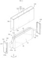
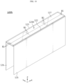
- FIG. 1 is a schematic perspective view of a cell assembly according to an embodiment of the present disclosure
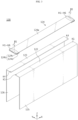
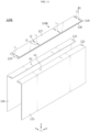
- FIG. 2 is a schematic exploded perspective view of the cell assembly of FIG. 1
- FIG. 3 is a perspective view showing the main components of a cell cover according to an embodiment of the present disclosure.
- the cell assembly 100 includes a cell stack 110 and the cell cover 120.
- the cell stack 110 may include one pouch-type battery cell 111 or two or more pouch-type battery cells 111 stacked.
- the pouch-type battery cell 111 may be manufactured by receiving an electrode assembly and an electrolyte in a pouch packaging of a laminate film including a soft metal and sealing the pouch packaging.
- the electrode assembly includes a positive electrode plate, a negative electrode plate and a separator interposed between the positive electrode plate and the negative electrode plate.
- the pouch-type battery cell 111 may include an electrode lead 111a that acts as an electrode lead, and the electrode lead 111a may be electrically connected to the electrode assembly and exposed to the outside of the pouch packaging.
- the electrode lead 111a includes a pair of a positive electrode lead and a negative electrode lead.
- the positive electrode lead and the negative electrode lead may be disposed at front and rear end portions in the lengthwise direction (X direction) of the pouch-type battery cell 111.
- the pouch-type battery cell 111 may have a receiving portion R in which the electrode assembly is received, and four edge portions E1 ⁇ E4 disposed around the receiving portion R.
- the four edge portions E1 ⁇ E4 include an upper edge portion E1, a lower edge portion E2, a front edge portion E3 and a rear edge portion E4, for example, as shown in FIG. 2 , on the basis of the receiving portion R in the pouch-type battery cell 111 standing upright.
- the edge portions E1 ⁇ E4 may be all sealing portions or three edge portions E2,E3,E4 or E1,E3,E4 except the upper edge portion E1 or the lower edge portion E2 may be sealing portions.
- the pouch-type battery cell 111 using a process of folding a sheet of laminate film when receiving the electrode assembly has three sealing portions
- the pouch-type battery cell 111 using a process of joining the edges of two sheets of laminate films when receiving the electrode assembly has four sealing portions.
- the three edge portions E2,E3,E4 or E1,E3,E4 or the four edge portions E1 ⁇ E4 of the pouch-type battery cell 111 may be sealing portions.
- the cell cover 120 may be configured to cover at least one pouch-type battery cell 111.
- the cell cover 120 may be configured to cover the cell stack 110.
- the cell cover 120 may be configured to cover the cell stack 110 such that a bottom portion of the cell stack 110 is exposed.
- the cell cover 120 may be configured to cover two side portions of the cell stack 110 in the widthwise direction of the cell stack 110 and a top portion of the cell stack 110.
- the cell cover 120 may be made of various types of materials to ensure stiffness.
- the cell cover 120 may be made of metal. When metal is used, it may be possible to keep the pouch-type battery cells 111 stacked more stably, and protect the pouch-type battery cells 111 from external impacts more safely.
- the cell cover 120 may be made of steel, especially, stainless steel (SUS).
- SUS stainless steel
- the cell cover 120 may be fully made of SUS.
- the cell cover 120 when the cell cover 120 covers the cell stack 110, it may be possible to stably keep the pouch-type battery cells 111 stacked and upright.
- the pouch-type battery cells 111 may be vulnerable to external impacts and have low hardness due to the outer packaging made of a soft material. Accordingly, it is not easy to receive the pouch-type battery cells 111 in a pack case 200.
- the pouch-type battery cells 111 since the pouch-type battery cells 111 are received in the cell cover 120, it may be possible to prevent damage or breakage of the pouch-type battery cells 111 from external impacts and stably keep them stacked in the pack case 200.
- the cell assembly 100 may further include a busbar assembly 130.
- the busbar assembly 130 may include a terminal busbar 131 electrically connected to the electrode lead 111a of the pouch-type battery cell 111 received in the cell cover 120, and be coupled to a front open end portion O and a rear open end portion of the cell cover 120.
- the busbar assembly 130 may include the terminal busbar 131, and a busbar frame 132 that supports the terminal busbar 131 and is mounted and demounted on/from the front open end portion O or the rear open end portion of the cell cover 120 by snap-fit.
- the terminal busbar 131 may be made of, for example, metal such as copper, nickel and aluminum, and the busbar frame 132 may be made of, for example, an electrically insulating material such as plastics.
- the busbar frame 132 may be approximately in the shape of a plate of a sufficient size to cover the front open end portion O or the rear open end portion of the cell cover 120, and have a lead slit 132a to allow the electrode lead 111a of the pouch-type battery cell 111 to pass through.
- the electrode lead 111a of the pouch-type battery cell 111 may be connected to the terminal busbar 131 through the lead slit 132a. In this instance, a welding process may be performed to fix the electrode lead 11 1a to the terminal busbar 131.
- the positive electrode leads of two pouch-type battery cells 111 may be connected to the terminal busbar 131 at the front open end portion O of the cell cover 120, and the negative electrode leads may be connected to the terminal busbar 131 at the rear open end portion of the cell cover 120.
- the terminal busbar 131 connected to the positive electrode leads may act as a positive terminal of the cell assembly 100
- the terminal busbar 131 connected to the negative electrode leads may act as a negative terminal of the cell assembly 100.
- the cell cover 120 according to the present disclosure is configured to adjust the width of the cell cover 120 according to the width of the cell stack 110.
- the cell cover 120 may include a width adjusting upper cover portion 121, a first side cover portion 125 and a second side cover portion 126, and like the exemplary configuration shown in FIGS. 4 and 6 , the width of the cell cover may be adjusted by variably adjusting the width of the width adjusting upper cover portion 121.
- the cell cover 120 will be described in more detail.
- the first side cover portion 125 may extend in the downward direction from an edge line at one side along the widthwise direction (Y direction) of the width adjusting upper cover portion 121.
- the first side cover portion 125 may be longer than the receiving portion R of the pouch-type battery cell 111.
- the first side cover portion 125 may be configured to cover one side portion of the cell stack 110.
- the first side cover portion 125 may be configured to fully cover one side portion of the cell stack 110 in order to prevent the exposure of one side portion of the cell stack 110.
- the second side cover portion 126 may extend in the downward direction from an edge line at the other side along the widthwise direction (Y direction) of the width adjusting upper cover portion 121.
- the second side cover portion 126 and the first side cover portion 125 may be parallel and symmetrical to each other.
- the second side cover portion 126 may be configured to cover the other side portion of the cell stack 110.
- the second side cover portion 126 may be configured to fully cover the other surface portion of the cell stack 110 in order to prevent the exposure of the other side portion of the cell stack 110.
- the width adjusting upper cover portion 121 may be configured to cover the upper surface portion of the cell stack 110.
- the width adjusting upper cover portion 121 may be configured to fully cover the upper surface portion of the cell stack 110 in order to prevent the exposure of the upper surface portion of the cell stack 110.
- the cell cover 120 for example, when the cell assembly 100 is disposed on the bottom surface of the pack case 200, it may be possible to stably keep the pouch-type battery cells 111 stacked and upright, and cool the pouch-type battery cells 111 by the indirect/direct contact between a cooling medium and the lower edge portions of the pouch-type battery cells 111.
- the width adjusting upper cover portion 121 includes a first upper cover portion 122 integrally formed with the first side cover portion 125, and a second upper cover portion 123 separated from the first upper cover portion 122 and integrally formed with the second side cover portion 126. Additionally, the width adjusting upper cover portion 121 may include a joint bracket unit 124 connected to the first upper cover portion 122 and the second upper cover portion 123, and configured to support the first upper cover portion 122 and the second upper cover portion 123 horizontally movably at the same height.
- the first upper cover portion 122 may be in the shape of a plate that is bent from the upper end of the first side cover portion 125. Additionally, the first upper cover portion 122 may have a width that is shorter than the width of the joint bracket unit 124.
- the second upper cover portion 123 may be in the shape of a plate that is bent from the upper end of the second side cover portion 126 and have a width that is shorter than the width of the joint bracket unit 124.
- the first upper cover portion 122 and the second upper cover portion 123 may be configured such that at least a portion of each of the first upper cover portion 122 and the second upper cover portion 123 is inserted into the joint bracket unit 124 as described below.
- the first upper cover portion 122 and the second upper cover portion 123 may be symmetrical to each other.
- first upper cover portion 122 and the first side cover portion 125 may be formed as a part, and the second upper cover portion 123 and the second side cover portion 126 may be formed as another part.
- the two parts may be linked by the joint bracket unit 124 as described below.
- the joint bracket unit 124 may include a cover plate portion 124a and a link portion 124b.
- the cover plate portion 124a may be in the shape of a plate having a length corresponding to a length of the cell cover 120. Additionally, the cover plate portion 124a may have a width that is at least equal to or smaller than the sum of the width of the first upper cover portion 122 and the width of the second upper cover portion 123.
- the cover plate portion 124a may act as a shield to prevent the exposure of the upper surface portion of the cell stack 110 between the first upper cover portion 122 and the second upper cover portion 123 when the first upper cover portion 122 and the second upper cover portion 123 as described below are placed with a gap therebetween.
- the link portion 124b is the component for connecting the joint bracket unit 124 to the first upper cover portion 122 or the joint bracket unit 124 to the second upper cover portion 123.
- the link portion 124b may be disposed in at least one end portion of the cover plate portion 124a along the lengthwise direction (X direction) of the cover plate portion 124a, and have a bent shape to cover the end portion of the first upper cover portion 122 and the end portion of the second upper cover portion 123 in the inward direction.
- the link portion 124b may include a bent portion 124c bent in the downward direction from the end portion of the cover plate portion 124a, and a support portion 124d extending in a direction perpendicular to the bent portion 124c and configured to support the first upper cover portion 122 and the second upper cover portion 123 together below the first upper cover portion 122 and the second upper cover portion 123.
- the support portion 124d may be spaced a predetermined distance apart from the cover plate portion 124a and have a plate surface parallel to the cover plate portion 124a. The distance between the support portion 124d and the cover plate portion 124a may correspond to the thickness of the first upper cover portion 122 and the second upper cover portion 123.
- the first upper cover portion 122 may be inserted into the space between the cover plate portion 124a and the link portion 124b.
- the two end portions of the first upper cover portion 122 may be supported by two link portions 124b.
- the first upper cover portion 122 may be connected to the joint bracket unit 124 so that the first upper cover portion 122 is not allowed to move in the front-rear direction ( ⁇ X direction) and the up-down direction ( ⁇ Z direction) and only allowed to move in the left-right direction ( ⁇ Y direction).
- the two end portions of the second upper cover portion 123 may be inserted into the space between the cover plate portion 124a and the link portion 124b in a direction facing the two end portions of the first upper cover portion 122. As shown in FIG. 4 , the two end portions of the second upper cover portion 123 may be also supported by the two link portions 124b, and the second upper cover portion 123 may be connected to the joint bracket unit 124 so that the second upper cover portion 123 is not allowed to move in the front-rear direction ( ⁇ X direction) and the up-down direction ( ⁇ Z direction), and only allowed to move in the left-right direction ( ⁇ Y direction).
- the horizontal width of the cell cover 120 may be adjusted by relatively moving the first upper cover portion 122 or the second upper cover portion 123 in the left-right direction with respect to the joint bracket unit 124.
- the first upper cover portion 122 and the second upper cover portion 123 are coupled to the joint bracket unit 124, as shown in FIG. 6 , each of the first upper cover portion 122 and the second upper cover portion 123 is partially pulled from the joint bracket unit 124. Accordingly, as the gap between the first side cover portion 125 and the second side cover portion 126 increases, the internal space of the cell cover 120 may be expanded.
- the cell cover 120 may be configured such that the gap between the first upper cover portion 122 and the second upper cover portion 123 may be adjusted and the adjusted gap may be maintained.
- the joint bracket unit 124 may include at least one first fastening hole H1 ⁇ H6 at a preset location, and the first upper cover portion 122 and the second upper cover portion 123 may include at least one second fastening hole K1,K4 that vertically match the first fastening holes H1 ⁇ H6 by the relative movement with respect to the joint bracket unit 124.
- a fastener may be inserted into the first fastening holes H1 ⁇ H6 and the second fastening holes K1,K4 that vertically match each other.
- At least one of the first fastening holes H1 ⁇ H6 or the second fastening holes K1,K4 may have screw threads, and the fastener may be a bolt B1 that may be fastened to the screw threads.
- first fastening holes H1 ⁇ H6 and the second fastening holes K1,K4 may be disposed at two end portions of the width adjusting upper cover portion 121.
- six first fastening holes H1 ⁇ H6 may be disposed at each of one end portion and the other portion of the joint bracket unit 124
- one second fastening hole K1,K4 may be disposed at each of one end portion and the other portion of the first upper cover portion 122 and each of one end portion and the other portion of the second upper cover portion 123.
- first fastening holes H1 ⁇ H6 may be disposed at an overlapping area of the cover plate portion 124a and the support portion 124d in the joint bracket unit 124, and be spaced apart from each other along the widthwise direction of the joint bracket unit 124. Additionally, the second fastening hole K1 of the first upper cover portion 122 and the second fastening hole K4 of the second upper cover portion 123 may be located on the same line as the six first fastening holes H1 ⁇ H6.
- one of the first fastening holes H1 ⁇ H6 may vertically match the second fastening hole K1 or the second fastening hole K4 of the first upper cover portion.
- the first upper cover portion 122 and the joint bracket unit 124 may be fixed and coupled by installing the bolt in the second fastening hole K1 of the first upper cover portion 122 and the first fastening hole H1 among the first fastening holes H1 ⁇ H6 of the joint bracket unit 124 that matches it.
- the second upper cover portion 123 and the joint bracket unit 124 may be fixed and coupled by installing the bolt B1 in the second fastening hole K4 of the second upper cover portion 123 and the first fastening hole H4 among the first fastening holes H1 ⁇ H6 of the joint bracket unit 124 that matches it.
- the first upper cover portion 122 and the joint bracket unit 124 may be fixed and coupled by installing the bolt B1 in the second fastening hole K1 of the first upper cover portion 122 and the first fastening hole H3 among the first fastening holes H1 ⁇ H6 of the joint bracket unit 124 that matches it.
- the second upper cover portion 123 and the joint bracket unit 124 may be fixed and coupled by installing the bolt in the second fastening hole K4 of the second upper cover portion 123 and the first fastening hole H6 among the first fastening holes H1 ⁇ H6 of the joint bracket unit 124 that matches it.
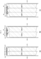
- the width of the cell cover 120 according to an embodiment of the present disclosure as described above can be adjusted, for example, as shown in FIGS. 8(a), 8(b) and 8(c) , it may be possible to receive the pouch-type battery cells 111 having different thicknesses as indicated by "Cell_1" and “Cell_2" or additional pouch-type battery cell(s) 111 using the same cell cover 120.
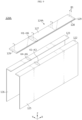
- FIG. 9 is a perspective view showing the main components of the cell cover 120A according to a second embodiment of the present disclosure
- FIG. 10 is an assembled perspective view of the cell cover 120A of FIG. 9
- FIG. 11 is a perspective view showing the main components of the cell cover 120B according to a third embodiment of the present disclosure
- FIG. 12 is an assembled perspective view of the cell cover 120B of FIG. 11 .
- the other embodiments of the present disclosure is mainly different in the joint bracket unit 124 of the cell cover and the other components are substantially the same. Accordingly, the following description will be made based on the joint bracket unit 124.
- the joint bracket unit 124A of the cell assembly according to the second embodiment of the present disclosure may cover and support not only the two end portions of first and second upper cover portions 122,123 but also parts between the two end portions of the first and second upper cover portions 122,123.
- the joint bracket unit 124A may include a first cover plate portion 127 disposed on the first upper cover portion 122 and the second upper cover portion 123, a second cover plate portion 128 disposed below the first upper cover portion 122 and the second upper cover portion 123, and a connection portion 129 covering the end portion of the first upper cover portion 122 and the end portion of the second upper cover portion 123 together and connecting the first cover plate portion 127 to the second cover plate portion 128.
- the distance between the first cover plate portion 127 and the second cover plate portion 128 may correspond to the thickness of the first upper cover portion 122 and the second upper cover portion 123. Additionally, the joint bracket unit 124 may be configured to push the first upper cover portion 122 and the second upper cover portion 123 into the space between the first cover plate portion 127 and the second cover plate portion 128.
- the joint bracket unit 124A according to the second embodiment of the present disclosure may have higher durability and support the first and second upper cover portions 122,123 more stably than the joint bracket unit 124 of the previous embodiment. Accordingly, in particular, it may be effective when applied to the cell cover 120A that will accommodate the long pouch-type battery cells 111.
- the joint bracket unit 124A may have, for example, six first fastening holes H1 ⁇ H6 arranged at a predetermined interval along the lengthwise direction (X direction) of the joint bracket unit 124A. That is, the first fastening holes H1 ⁇ H6 may be disposed in not only the two end portions of the joint bracket unit 124A but also the area between them.
- the second fastening holes K1 ⁇ K3 of the first upper cover portion 122 and the second fastening holes K4 ⁇ K6 of the second upper cover portion 123 may be located on the same line as the six first fastening holes H1 ⁇ H6.
- the first upper cover portion 122 may have three second fastening holes K1 ⁇ K3 arranged at a predetermined interval
- the second upper cover portion 123 may have three second fastening holes K4 ⁇ K6 arranged at a predetermined interval.
- the first upper cover portion 122 and the joint bracket unit 124 may be fixed and coupled by installing the bolt B1 in the second fastening hole K1 ⁇ K3 of the first upper cover portion 122 and the first fastening hole H1 among the first fastening holes H1 ⁇ H6 of the joint bracket unit 124 that matches it.
- the second upper cover portion 123 and the joint bracket unit 124 may be fixed and coupled by installing the bolt B1 in the second fastening hole K4 ⁇ K6 of the second upper cover portion 123 and the first fastening hole H4 among the first fastening holes H1 ⁇ H6 of the joint bracket unit 124 that matches it.
- the joint bracket unit 124B of the cell assembly according to the third embodiment of the present disclosure and the joint bracket unit 124A of the second embodiment are different in the shape of the fastening hole. That is, the first cover plate portion 127 of the joint bracket unit 124B according to the third embodiment may have first long holes J1,J2 at a preset location, and the first upper cover portion 122 and the second upper cover portion 123 may have second long holes P1,P2, respectively. By the horizontal movement of the first upper cover portion 122 or the second upper cover portion 123, the first long holes J1,J2 and the second long holes P1,P2 may match each other at least in part. For example, as shown in FIG.
- the joint bracket unit 124B and the first and second upper cover portions 122,123 may be fixed and coupled by installing the bolt at a location at which the first long holes J1,J2 of the joint bracket unit 124B and the second long holes P1,P2 of the first and second upper cover portions 122,123 vertically match each other.
- the joint bracket unit 124B and the first upper cover portion 122 or the joint bracket unit 124B and the second upper cover portion 123 may be fixed with the bolt B1. Accordingly, according to the third embodiment, it may be possible to adjust the width of the cell cover 120B more finely than the previous embodiment.
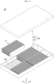
- FIG. 13 is a schematic diagram of the battery pack 10 according to an embodiment of the present disclosure
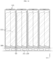
- FIG. 14 is a partial cross-sectional view of the battery pack 10 according to an embodiment of the present disclosure.
- the battery pack 10 may include a cell assembly group 11 including the cell assemblies 100 stacked in a direction and the pack case 200 accommodating at least one cell assembly group 11.
- the cell assembly group 11 may include a predetermined number of cell assemblies 100 stacked with the first side cover portion 125 or the second side cover portion 126 facing each other. Additionally, although not shown in the drawings for convenience, the cell assemblies 100 may be connected in series or in parallel.
- the pack case 200 includes a pack tray 210 and a pack cover 220.
- the pack tray 210 may be in the shape of a box with an open top, so the plurality of cell assembly groups 11 may be received in the internal space.
- the pack cover 220 may be in the shape of a cover that covers the open top of the pack tray 210. In this instance, the pack cover 220 may be in the shape of a box with an open bottom.
- the pack case 200 may be made of plastics or metals.
- the material of the pack case 200 may include various types of packaging materials of the battery pack 10 known at the time of filing the application.
- a bottom plate of the pack tray 210 on which the cell assembly group 11 is mounted may have a thermally conductive adhesive 300. Accordingly, the cell assembly group 11 may be adhered and fixed to the pack tray 210.
- the pack tray 210 may include a cooling channel 211 in which a cooling medium flows. That is, the pack tray 210 itself may act as a heatsink due to the cooling channel 211 in the bottom plate.
- the heatsink refers to an object that absorbs heat and carries it away from another object through direct/indirect thermal contact.
- the cell cover 120 may be configured such that the lower edge portion E2 of the pouch-type battery cell 111 is exposed. Accordingly, when the cell assembly group 11 is mounted on the bottom plate of the pack tray 210, the lower edge portion E2 of the pouch-type battery cell 111 may directly contact the bottom plate of the pack tray 210. In this instance, the thermally conductive adhesive 300 filled between the lower edge portion E2 of the pouch-type battery cell 111 and the bottom plate of the pack tray 210 may improve fixation of the pouch-type battery cells 111 and heat dissipation performance.
- the battery pack 10 does not need a cooling structure between the pouch-type battery cell 111 and the pack case 200, thereby achieving efficient cooling performance.
- the pack tray 210 may have a fixing groove to which the lower end of the cell cover 120 is inserted and fixed. That is, the lower end of the first side cover portion 125 and the lower end of the second side cover portion 126 of the cell cover 120 may be inserted into the bottom plate of the pack tray 210. For example, as indicated by 'Q1' in FIG. 14 , a portion of the lower end of each cell cover 120 may be inserted and fixed to the bottom plate of the pack tray 210. Accordingly, the cell covers 120 may stand upright in the pack tray 210 more stably.
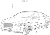
- the battery pack 10 according to the present disclosure may be used as an energy source for driving a vehicle. That is, the vehicle V according to the present disclosure may include the battery pack 10 according to the present disclosure as shown in FIG. 15 .
- the vehicle according to the present disclosure may include, for example, a predetermined vehicle that is powered by electricity such as an electric vehicle or a hybrid electric vehicle.
- the vehicle according to the present disclosure may further include a variety of other components included in the vehicle, for example, a vehicle body or a motor.
Landscapes
- Chemical & Material Sciences (AREA)
- Chemical Kinetics & Catalysis (AREA)
- Electrochemistry (AREA)
- General Chemical & Material Sciences (AREA)
- Engineering & Computer Science (AREA)
- Manufacturing & Machinery (AREA)
- Aviation & Aerospace Engineering (AREA)
- Battery Mounting, Suspending (AREA)
- Secondary Cells (AREA)
- Connection Of Batteries Or Terminals (AREA)
Abstract
Description
- The present disclosure relates to a cell assembly and a battery pack and a vehicle including the same, and more particularly, to a cell assembly having a cell cover with variably adjustable width according to the thickness or number of pouch-type battery cells that are received in the cell cover and a battery pack and a vehicle including the same.
- The present application claims priority to
Korean Patent Application No. 10-2022-0110376 filed on August 31, 2022 Korean Patent Application No. 10-2023-0065245 filed on May 19, 2023 - With the development of mobile technology and the growing demand for mobile devices, the demand for secondary batteries as an energy source is rapidly increasing. Among secondary batteries, nickel-cadmium batteries or hydrogen-ion batteries have been used, but recently, lithium secondary batteries are being used in a wide range of applications. Compared to nickel-based secondary batteries, lithium secondary batteries have little or no memory effect, and thus have advantages that recharging can be done whenever it is convenient, the self-discharge rate is very low and the energy density is high.
- Lithium secondary batteries primarily comprise lithium-based oxides and carbon materials for a positive electrode active material and a negative electrode active material, respectively. A lithium secondary battery includes an electrode assembly including a positive electrode plate and a negative electrode plate coated with the positive electrode active material and the negative electrode active material, respectively, with a separator interposed between the positive electrode plate and the negative electrode plate, and a sealed packaging or battery case accommodating the electrode assembly together with an electrolyte solution.
- In general, secondary batteries may be classified into can-type secondary batteries in which the electrode assembly is included in a metal can and pouch-type secondary batteries in which the electrode assembly is included in a pouch of an aluminum laminate sheet, according to the shape of the battery case.
- Pouch-type secondary batteries are light-weight and can be stacked with reduced dead spaces, so they have many advantages including high energy density per volume. However, pouch-type secondary batteries are relatively vulnerable to external impacts and low efficient in assembling.
- A typical battery pack includes at least one battery module and a pack case accommodating the at least one battery module, wherein each battery module includes a plurality of pouch-type battery cells and a module case accommodating the plurality of pouch-type battery cells. An example of the battery module, the prior art document (
Korean Patent Publication No. 10-2015-0044599 - However, assembling the pouch-type battery cells into a battery module and mounting each battery module in the battery pack may be unfavorable in terms of energy density. In particular, since the battery module includes not only the pouch-type battery cells but also many components such as the module case, the frame for stacking and the like, the battery pack may unnecessarily increase in weight and volume. To address this problem, recently, intensive efforts are being made in research and development of so-called cell to pack type battery pack in which the plurality of pouch-type battery cells is directly mounted in the pack case without forming the battery module.
- However, in the mounting process, fixing the pouch-type battery cell having the soft pouch case to the pack case is not easy and there are damage risks. Additionally, there are concerns about durability against external impacts. As disclosed in
KR Patent Publication No. 10-2023-0021607 - The present disclosure is directed to providing a cell assembly including a cell cover with adjustable width according to the thickness or number of pouch-type battery cells to mount the pouch-type battery cells in a pack case with stability and space efficiency.
- The present disclosure is further directed to providing a battery pack that is simple to assemble and has enhanced energy density by using the cell assembly.
- The technical problem to be solved by the present disclosure is not limited to the above-described problems, and these and other problems will be clearly understood by those skilled in the art from the following description.
- According to an aspect of the present disclosure, there is provided a cell assembly including a cell stack including one pouch-type battery cell or two or more pouch-type battery cells stacked; and a cell cover covering two side portions of the cell stack along a widthwise direction of the cell stack and a top portion of the cell stack, wherein the cell cover is configured to adjust a width of the cell cover according to a width of the cell stack.
- The cell cover may be configured to cover the cell stack such that a bottom portion of the cell stack is exposed.
- The cell cover may include a width adjusting upper cover portion covering an upper surface portion of the cell stack, and having a variably adjustable width; a first side cover portion extending in a downward direction from an edge at one side of the width adjusting upper cover portion and covering one side portion of the cell stack; and a second side cover portion extending in the downward direction from an edge at the other side of the width adjusting upper cover portion and covering the other side portion of the cell stack.
- The width adjusting upper cover portion may include a first upper cover portion integrally formed with the first side cover portion; a second upper cover portion separated from the first upper cover portion, and integrally formed with the second side cover portion; and a joint bracket unit connected to the first upper cover portion and the second upper cover portion, and configured to support the first upper cover portion and the second upper cover portion horizontally movably at a same height.
- The joint bracket unit may include a cover plate portion disposed on the first upper cover portion and the second upper cover portion; and a link portion disposed in at least one end portion of the cover plate portion along a lengthwise direction of the cover plate portion, and having a bent shape to cover an end portion of the first upper cover portion and an end portion of the second upper cover portion in an inward direction.
- The link portion may include a bent portion bent in the downward direction from an end portion of the cover plate portion; and a support portion extending in a direction perpendicular to the bent portion, and configured to support the first upper cover portion and the second upper cover portion together below the first upper cover portion and the second upper cover portion.
- The joint bracket unit may have a first fastening hole at a preset location, and the first upper cover portion and the second upper cover portion may include at least one second fastening hole that vertically matches the first fastening hole by a relative movement with respect to the joint bracket unit.
- The joint bracket unit may include a first cover plate portion disposed on the first upper cover portion and the second upper cover portion; a second cover plate portion disposed below the first upper cover portion and the second upper cover portion; and a connection portion covering an end portion of the first upper cover portion and an end portion of the second upper cover portion together and connecting the first cover plate portion to the second cover plate portion.
- The first cover plate portion may have a first long hole at a preset location, each of the first upper cover portion and the second upper cover portion may have a second long hole, and the first long hole and the second long hole may match each other at least in part by the horizontal movement of the first upper cover portion or the second upper cover portion.
- The cell assembly may further include a busbar assembly having a terminal busbar electrically connected to an electrode lead of the pouch-type battery cell.
- According to another aspect of the present disclosure, there is provided a battery pack including a cell assembly group including the cell assemblies stacked in a direction; and a pack case including a pack tray on which the cell assembly group is mounted, and a pack cover covering the cell assembly group.
- The cell assembly group may be adhered and fixed to an upper surface of the pack tray.
- The pack tray may include a cooling channel in which a cooling medium flows.
- The pack tray may have a fixing groove to which a lower end of the cell cover is inserted and fixed.
- According to still another aspect of the present disclosure, there is provided a vehicle including the battery pack.
- According to an aspect of the present disclosure, it may be possible to provide the cell assembly including the cell cover with adjustable width according to the thickness or number of pouch-type battery cells that are received in the cell cover.
- According to another aspect of the present disclosure, it may be possible to simplify the assembly process of the battery pack and improve energy density by using the cell assembly to assemble the battery pack.
- The present disclosure may have many other effects, and these effects will be described in each embodiment, or regarding effects that can be easily inferred by those skilled in the art, the corresponding description is omitted.
-
-
FIG. 1 is a schematic perspective view of a cell assembly according to an embodiment of the present disclosure. -
FIG. 2 is a schematic exploded perspective view of the cell assembly ofFIG. 1 . -
FIG. 3 is a perspective view showing the main components of a cell cover according to an embodiment of the present disclosure. -
FIG. 4 is an assembled perspective view of the cell cover ofFIG. 3 . -
FIG. 5 is a partial enlarged view of the cell cover ofFIG. 4 . -
FIG. 6 is a diagram showing an example of adjusting up the width of the cell cover ofFIG. 4 . -
FIG. 7 is a partial enlarged view of the cell cover ofFIG. 6 . -
FIG. 8 is a diagram showing examples of width adjustment of a cell cover according to an embodiment of the present disclosure to receive pouch-type battery cells according to situations. -
FIG. 9 is a perspective view showing the main components of a cell cover according to another embodiment of the present disclosure. -
FIG. 10 is an assembled perspective view of the cell cover ofFIG. 9 . -
FIG. 11 is a perspective view showing the main components of a cell cover according to still another embodiment of the present disclosure. -
FIG. 12 is an assembled perspective view of the cell cover ofFIG. 11 . -
FIG. 13 is a schematic diagram of a battery pack according to an embodiment of the present disclosure. -
FIG. 14 is a partial cross-sectional view of a battery pack according to an embodiment of the present disclosure. -
FIG. 15 is a schematic diagram of a vehicle including a battery pack according to an embodiment of the present disclosure. - Hereinafter, exemplary embodiments of the present disclosure will be described in detail with reference to the accompanying drawings. Prior to the description, it should be understood that the terms or words used in the specification and the appended claims should not be construed as being limited to general and dictionary meanings, but rather interpreted based on the meanings and concepts corresponding to the technical aspect of the present disclosure on the basis of the principle that the inventor is allowed to define the terms appropriately for the best explanation.
- Therefore, the embodiments described herein and the illustrations shown in the drawings are exemplary embodiments of the present disclosure to describe the technical aspect of the present disclosure and are not intended to be limiting, so it should be understood that a variety of other equivalents and modifications could have been made thereto at the time that the application was filed.
-
FIG. 1 is a schematic perspective view of a cell assembly according to an embodiment of the present disclosure,FIG. 2 is a schematic exploded perspective view of the cell assembly ofFIG. 1 , andFIG. 3 is a perspective view showing the main components of a cell cover according to an embodiment of the present disclosure. - Referring to
FIGS. 1 to 3 , thecell assembly 100 according to an embodiment of the present disclosure includes acell stack 110 and thecell cover 120. - The
cell stack 110 may include one pouch-type battery cell 111 or two or more pouch-type battery cells 111 stacked. The pouch-type battery cell 111 may be manufactured by receiving an electrode assembly and an electrolyte in a pouch packaging of a laminate film including a soft metal and sealing the pouch packaging. Here, the electrode assembly includes a positive electrode plate, a negative electrode plate and a separator interposed between the positive electrode plate and the negative electrode plate. - Referring to
FIG. 2 , the pouch-type battery cell 111 may include anelectrode lead 111a that acts as an electrode lead, and theelectrode lead 111a may be electrically connected to the electrode assembly and exposed to the outside of the pouch packaging. Theelectrode lead 111a includes a pair of a positive electrode lead and a negative electrode lead. Here, the positive electrode lead and the negative electrode lead may be disposed at front and rear end portions in the lengthwise direction (X direction) of the pouch-type battery cell 111. - Additionally, the pouch-
type battery cell 111 may have a receiving portion R in which the electrode assembly is received, and four edge portions E1~E4 disposed around the receiving portion R. The four edge portions E1~E4 include an upper edge portion E1, a lower edge portion E2, a front edge portion E3 and a rear edge portion E4, for example, as shown inFIG. 2 , on the basis of the receiving portion R in the pouch-type battery cell 111 standing upright. - Here, the edge portions E1~E4 may be all sealing portions or three edge portions E2,E3,E4 or E1,E3,E4 except the upper edge portion E1 or the lower edge portion E2 may be sealing portions. In addition, the pouch-
type battery cell 111 using a process of folding a sheet of laminate film when receiving the electrode assembly has three sealing portions, and the pouch-type battery cell 111 using a process of joining the edges of two sheets of laminate films when receiving the electrode assembly has four sealing portions. Accordingly, the three edge portions E2,E3,E4 or E1,E3,E4 or the four edge portions E1~E4 of the pouch-type battery cell 111 may be sealing portions. - The
cell cover 120 may be configured to cover at least one pouch-type battery cell 111. In other words, thecell cover 120 may be configured to cover thecell stack 110. In particular, thecell cover 120 may be configured to cover thecell stack 110 such that a bottom portion of thecell stack 110 is exposed. Thecell cover 120 may be configured to cover two side portions of thecell stack 110 in the widthwise direction of thecell stack 110 and a top portion of thecell stack 110. - The
cell cover 120 may be made of various types of materials to ensure stiffness. In particular, thecell cover 120 may be made of metal. When metal is used, it may be possible to keep the pouch-type battery cells 111 stacked more stably, and protect the pouch-type battery cells 111 from external impacts more safely. In particular, thecell cover 120 may be made of steel, especially, stainless steel (SUS). For example, thecell cover 120 may be fully made of SUS. - Accordingly, when the
cell cover 120 covers thecell stack 110, it may be possible to stably keep the pouch-type battery cells 111 stacked and upright. In particular, the pouch-type battery cells 111 may be vulnerable to external impacts and have low hardness due to the outer packaging made of a soft material. Accordingly, it is not easy to receive the pouch-type battery cells 111 in apack case 200. However, in the case of the present disclosure, since the pouch-type battery cells 111 are received in thecell cover 120, it may be possible to prevent damage or breakage of the pouch-type battery cells 111 from external impacts and stably keep them stacked in thepack case 200. Accordingly, there is no need to add, to abattery pack 10, a module case, a frame for stacking, a fastener for maintaining the stack and so on. As a result, it may be possible to receive a larger number ofbattery cells 111 in thepack case 200, thereby enhancing energy density of thebattery pack 10. - Referring to
FIGS. 1 and2 , thecell assembly 100 according to an embodiment of the present disclosure may further include abusbar assembly 130. - The
busbar assembly 130 may include aterminal busbar 131 electrically connected to theelectrode lead 111a of the pouch-type battery cell 111 received in thecell cover 120, and be coupled to a front open end portion O and a rear open end portion of thecell cover 120. - Specifically, referring to
FIG. 2 , thebusbar assembly 130 according to this embodiment may include theterminal busbar 131, and abusbar frame 132 that supports theterminal busbar 131 and is mounted and demounted on/from the front open end portion O or the rear open end portion of thecell cover 120 by snap-fit. - The
terminal busbar 131 may be made of, for example, metal such as copper, nickel and aluminum, and thebusbar frame 132 may be made of, for example, an electrically insulating material such as plastics. - The
busbar frame 132 may be approximately in the shape of a plate of a sufficient size to cover the front open end portion O or the rear open end portion of thecell cover 120, and have alead slit 132a to allow theelectrode lead 111a of the pouch-type battery cell 111 to pass through. Theelectrode lead 111a of the pouch-type battery cell 111 may be connected to theterminal busbar 131 through thelead slit 132a. In this instance, a welding process may be performed to fix theelectrode lead 11 1a to theterminal busbar 131. - For example, in
FIG. 2 , the positive electrode leads of two pouch-type battery cells 111 may be connected to theterminal busbar 131 at the front open end portion O of thecell cover 120, and the negative electrode leads may be connected to theterminal busbar 131 at the rear open end portion of thecell cover 120. In this case, theterminal busbar 131 connected to the positive electrode leads may act as a positive terminal of thecell assembly 100, and theterminal busbar 131 connected to the negative electrode leads may act as a negative terminal of thecell assembly 100. - Meanwhile, the
cell cover 120 according to the present disclosure is configured to adjust the width of thecell cover 120 according to the width of thecell stack 110. - For example, as shown in
FIG. 2 , thecell cover 120 may include a width adjustingupper cover portion 121, a firstside cover portion 125 and a secondside cover portion 126, and like the exemplary configuration shown inFIGS. 4 and6 , the width of the cell cover may be adjusted by variably adjusting the width of the width adjustingupper cover portion 121. Hereinafter, thecell cover 120 will be described in more detail. - First, the first
side cover portion 125 may extend in the downward direction from an edge line at one side along the widthwise direction (Y direction) of the width adjustingupper cover portion 121. The firstside cover portion 125 may be longer than the receiving portion R of the pouch-type battery cell 111. - The first
side cover portion 125 may be configured to cover one side portion of thecell stack 110. In particular, as shown inFIG. 1 , the firstside cover portion 125 may be configured to fully cover one side portion of thecell stack 110 in order to prevent the exposure of one side portion of thecell stack 110. - The second
side cover portion 126 may extend in the downward direction from an edge line at the other side along the widthwise direction (Y direction) of the width adjustingupper cover portion 121. Preferably, the secondside cover portion 126 and the firstside cover portion 125 may be parallel and symmetrical to each other. - The second
side cover portion 126 may be configured to cover the other side portion of thecell stack 110. In particular, the secondside cover portion 126 may be configured to fully cover the other surface portion of thecell stack 110 in order to prevent the exposure of the other side portion of thecell stack 110. - The width adjusting
upper cover portion 121 may be configured to cover the upper surface portion of thecell stack 110. In particular, as shown inFIG. 1 , the width adjustingupper cover portion 121 may be configured to fully cover the upper surface portion of thecell stack 110 in order to prevent the exposure of the upper surface portion of thecell stack 110. - With the
cell cover 120, for example, when thecell assembly 100 is disposed on the bottom surface of thepack case 200, it may be possible to stably keep the pouch-type battery cells 111 stacked and upright, and cool the pouch-type battery cells 111 by the indirect/direct contact between a cooling medium and the lower edge portions of the pouch-type battery cells 111. - In particular, as shown in
FIG. 3 , the width adjustingupper cover portion 121 includes a firstupper cover portion 122 integrally formed with the firstside cover portion 125, and a secondupper cover portion 123 separated from the firstupper cover portion 122 and integrally formed with the secondside cover portion 126. Additionally, the width adjustingupper cover portion 121 may include ajoint bracket unit 124 connected to the firstupper cover portion 122 and the secondupper cover portion 123, and configured to support the firstupper cover portion 122 and the secondupper cover portion 123 horizontally movably at the same height. - The first
upper cover portion 122 may be in the shape of a plate that is bent from the upper end of the firstside cover portion 125. Additionally, the firstupper cover portion 122 may have a width that is shorter than the width of thejoint bracket unit 124. - The second
upper cover portion 123 may be in the shape of a plate that is bent from the upper end of the secondside cover portion 126 and have a width that is shorter than the width of thejoint bracket unit 124. The firstupper cover portion 122 and the secondupper cover portion 123 may be configured such that at least a portion of each of the firstupper cover portion 122 and the secondupper cover portion 123 is inserted into thejoint bracket unit 124 as described below. Preferably, the firstupper cover portion 122 and the secondupper cover portion 123 may be symmetrical to each other. - That is, the first
upper cover portion 122 and the firstside cover portion 125 may be formed as a part, and the secondupper cover portion 123 and the secondside cover portion 126 may be formed as another part. The two parts may be linked by thejoint bracket unit 124 as described below. - As shown in
FIG. 3 , thejoint bracket unit 124 according to this embodiment may include acover plate portion 124a and alink portion 124b. - The
cover plate portion 124a may be in the shape of a plate having a length corresponding to a length of thecell cover 120. Additionally, thecover plate portion 124a may have a width that is at least equal to or smaller than the sum of the width of the firstupper cover portion 122 and the width of the secondupper cover portion 123. - The
cover plate portion 124a may act as a shield to prevent the exposure of the upper surface portion of thecell stack 110 between the firstupper cover portion 122 and the secondupper cover portion 123 when the firstupper cover portion 122 and the secondupper cover portion 123 as described below are placed with a gap therebetween. - The
link portion 124b is the component for connecting thejoint bracket unit 124 to the firstupper cover portion 122 or thejoint bracket unit 124 to the secondupper cover portion 123. Thelink portion 124b may be disposed in at least one end portion of thecover plate portion 124a along the lengthwise direction (X direction) of thecover plate portion 124a, and have a bent shape to cover the end portion of the firstupper cover portion 122 and the end portion of the secondupper cover portion 123 in the inward direction. - More specifically, as shown in
FIG. 3 , thelink portion 124b may include abent portion 124c bent in the downward direction from the end portion of thecover plate portion 124a, and asupport portion 124d extending in a direction perpendicular to thebent portion 124c and configured to support the firstupper cover portion 122 and the secondupper cover portion 123 together below the firstupper cover portion 122 and the secondupper cover portion 123. - The
support portion 124d may be spaced a predetermined distance apart from thecover plate portion 124a and have a plate surface parallel to thecover plate portion 124a. The distance between thesupport portion 124d and thecover plate portion 124a may correspond to the thickness of the firstupper cover portion 122 and the secondupper cover portion 123. - With the
link portion 124b, as shown inFIGS. 3 to 5 , the firstupper cover portion 122 may be inserted into the space between thecover plate portion 124a and thelink portion 124b. In particular, as shown inFIG. 4 , the two end portions of the firstupper cover portion 122 may be supported by twolink portions 124b. In this case, the firstupper cover portion 122 may be connected to thejoint bracket unit 124 so that the firstupper cover portion 122 is not allowed to move in the front-rear direction (±X direction) and the up-down direction (±Z direction) and only allowed to move in the left-right direction (±Y direction). - The two end portions of the second
upper cover portion 123 may be inserted into the space between thecover plate portion 124a and thelink portion 124b in a direction facing the two end portions of the firstupper cover portion 122. As shown inFIG. 4 , the two end portions of the secondupper cover portion 123 may be also supported by the twolink portions 124b, and the secondupper cover portion 123 may be connected to thejoint bracket unit 124 so that the secondupper cover portion 123 is not allowed to move in the front-rear direction (±X direction) and the up-down direction (±Z direction), and only allowed to move in the left-right direction (±Y direction). - With the
cell cover 120, the horizontal width of thecell cover 120 may be adjusted by relatively moving the firstupper cover portion 122 or the secondupper cover portion 123 in the left-right direction with respect to thejoint bracket unit 124. For example, as shown inFIG. 4 , in a state that the firstupper cover portion 122 and the secondupper cover portion 123 are coupled to thejoint bracket unit 124, as shown inFIG. 6 , each of the firstupper cover portion 122 and the secondupper cover portion 123 is partially pulled from thejoint bracket unit 124. Accordingly, as the gap between the firstside cover portion 125 and the secondside cover portion 126 increases, the internal space of thecell cover 120 may be expanded. - Additionally, the
cell cover 120 according to this embodiment may be configured such that the gap between the firstupper cover portion 122 and the secondupper cover portion 123 may be adjusted and the adjusted gap may be maintained. - To this end, the
joint bracket unit 124 may include at least one first fastening hole H1~H6 at a preset location, and the firstupper cover portion 122 and the secondupper cover portion 123 may include at least one second fastening hole K1,K4 that vertically match the first fastening holes H1~H6 by the relative movement with respect to thejoint bracket unit 124. Additionally, a fastener may be inserted into the first fastening holes H1~H6 and the second fastening holes K1,K4 that vertically match each other. At least one of the first fastening holes H1~H6 or the second fastening holes K1,K4 may have screw threads, and the fastener may be a bolt B1 that may be fastened to the screw threads. - For example, as shown in
FIGS. 3 and4 , the first fastening holes H1~H6 and the second fastening holes K1,K4 may be disposed at two end portions of the width adjustingupper cover portion 121. Here, six first fastening holes H1~H6 may be disposed at each of one end portion and the other portion of thejoint bracket unit 124, and one second fastening hole K1,K4 may be disposed at each of one end portion and the other portion of the firstupper cover portion 122 and each of one end portion and the other portion of the secondupper cover portion 123. - Additionally, the six first fastening holes H1~H6 may be disposed at an overlapping area of the
cover plate portion 124a and thesupport portion 124d in thejoint bracket unit 124, and be spaced apart from each other along the widthwise direction of thejoint bracket unit 124. Additionally, the second fastening hole K1 of the firstupper cover portion 122 and the second fastening hole K4 of the secondupper cover portion 123 may be located on the same line as the six first fastening holes H1~H6. - Accordingly, when each of the two end portions of the first
upper cover portion 122 and the two end portions of the secondupper cover portion 123 is pushed into the space between thecover plate portion 124a and thesupport portion 124d of thejoint bracket unit 124, one of the first fastening holes H1~H6 may vertically match the second fastening hole K1 or the second fastening hole K4 of the first upper cover portion. In this case, for example, as shown inFIG. 5 , the firstupper cover portion 122 and thejoint bracket unit 124 may be fixed and coupled by installing the bolt in the second fastening hole K1 of the firstupper cover portion 122 and the first fastening hole H1 among the first fastening holes H1~H6 of thejoint bracket unit 124 that matches it. Likewise, the secondupper cover portion 123 and thejoint bracket unit 124 may be fixed and coupled by installing the bolt B1 in the second fastening hole K4 of the secondupper cover portion 123 and the first fastening hole H4 among the first fastening holes H1~H6 of thejoint bracket unit 124 that matches it. - Meanwhile, when extending the width of the
cell cover 120, after loosening the bolt B1 from thecell cover 120 ofFIG. 5 , at least one of the firstupper cover portion 122 or the secondupper cover portion 123 is partially pulled from thejoint bracket unit 124. Additionally, for example, as shown inFIG. 7 , the firstupper cover portion 122 and thejoint bracket unit 124 may be fixed and coupled by installing the bolt B1 in the second fastening hole K1 of the firstupper cover portion 122 and the first fastening hole H3 among the first fastening holes H1~H6 of thejoint bracket unit 124 that matches it. Likewise, the secondupper cover portion 123 and thejoint bracket unit 124 may be fixed and coupled by installing the bolt in the second fastening hole K4 of the secondupper cover portion 123 and the first fastening hole H6 among the first fastening holes H1~H6 of thejoint bracket unit 124 that matches it. - Accordingly, since the width of the
cell cover 120 according to an embodiment of the present disclosure as described above can be adjusted, for example, as shown inFIGS. 8(a), 8(b) and 8(c) , it may be possible to receive the pouch-type battery cells 111 having different thicknesses as indicated by "Cell_1" and "Cell_2" or additional pouch-type battery cell(s) 111 using thesame cell cover 120. - Subsequently, the cell assemblies according to other embodiments of the present disclosure will be described with reference to
FIGS. 9 to 12 . -
FIG. 9 is a perspective view showing the main components of thecell cover 120A according to a second embodiment of the present disclosure,FIG. 10 is an assembled perspective view of thecell cover 120A ofFIG. 9 ,FIG. 11 is a perspective view showing the main components of thecell cover 120B according to a third embodiment of the present disclosure, andFIG. 12 is an assembled perspective view of thecell cover 120B ofFIG. 11 . - The same element as the previous embodiment is given the same reference sign, and a redundant description of the same element is omitted and difference(s) between this embodiment and the previous embodiment will be described.
- When compared with the previous embodiment, the other embodiments of the present disclosure is mainly different in the
joint bracket unit 124 of the cell cover and the other components are substantially the same. Accordingly, the following description will be made based on thejoint bracket unit 124. - As opposed to the
joint bracket unit 124 of the previous embodiment, thejoint bracket unit 124A of the cell assembly according to the second embodiment of the present disclosure may cover and support not only the two end portions of first and second upper cover portions 122,123 but also parts between the two end portions of the first and second upper cover portions 122,123. - As shown in
FIGS. 9 and10 , thejoint bracket unit 124A according to the second embodiment may include a firstcover plate portion 127 disposed on the firstupper cover portion 122 and the secondupper cover portion 123, a secondcover plate portion 128 disposed below the firstupper cover portion 122 and the secondupper cover portion 123, and aconnection portion 129 covering the end portion of the firstupper cover portion 122 and the end portion of the secondupper cover portion 123 together and connecting the firstcover plate portion 127 to the secondcover plate portion 128. - The distance between the first
cover plate portion 127 and the secondcover plate portion 128 may correspond to the thickness of the firstupper cover portion 122 and the secondupper cover portion 123. Additionally, thejoint bracket unit 124 may be configured to push the firstupper cover portion 122 and the secondupper cover portion 123 into the space between the firstcover plate portion 127 and the secondcover plate portion 128. - The
joint bracket unit 124A according to the second embodiment of the present disclosure may have higher durability and support the first and second upper cover portions 122,123 more stably than thejoint bracket unit 124 of the previous embodiment. Accordingly, in particular, it may be effective when applied to thecell cover 120A that will accommodate the long pouch-type battery cells 111. - Additionally, as shown in
FIG. 9 , thejoint bracket unit 124A according to the second embodiment may have, for example, six first fastening holes H1~H6 arranged at a predetermined interval along the lengthwise direction (X direction) of thejoint bracket unit 124A. That is, the first fastening holes H1~H6 may be disposed in not only the two end portions of thejoint bracket unit 124A but also the area between them. - Additionally, the second fastening holes K1~K3 of the first
upper cover portion 122 and the second fastening holes K4~K6 of the secondupper cover portion 123 may be located on the same line as the six first fastening holes H1~H6. In this instance, as shown inFIG. 9 , the firstupper cover portion 122 may have three second fastening holes K1~K3 arranged at a predetermined interval, and the secondupper cover portion 123 may have three second fastening holes K4~K6 arranged at a predetermined interval. - Accordingly, as shown in
FIG. 10 , the firstupper cover portion 122 and thejoint bracket unit 124 may be fixed and coupled by installing the bolt B1 in the second fastening hole K1~K3 of the firstupper cover portion 122 and the first fastening hole H1 among the first fastening holes H1~H6 of thejoint bracket unit 124 that matches it. Likewise, the secondupper cover portion 123 and thejoint bracket unit 124 may be fixed and coupled by installing the bolt B1 in the second fastening hole K4~K6 of the secondupper cover portion 123 and the first fastening hole H4 among the first fastening holes H1~H6 of thejoint bracket unit 124 that matches it. - As described above, when extending the width of the
cell cover 120, after loosening the bolt B1, at least one of the firstupper cover portion 122 or the secondupper cover portion 123 is partially pulled from thejoint bracket unit 124 and the bolt B1 is installed again in the first fastening holes H1~H6 and the second fastening holes K1~K6 that vertically match. - Meanwhile, as shown in
FIG. 11 , thejoint bracket unit 124B of the cell assembly according to the third embodiment of the present disclosure and thejoint bracket unit 124A of the second embodiment are different in the shape of the fastening hole. That is, the firstcover plate portion 127 of thejoint bracket unit 124B according to the third embodiment may have first long holes J1,J2 at a preset location, and the firstupper cover portion 122 and the secondupper cover portion 123 may have second long holes P1,P2, respectively. By the horizontal movement of the firstupper cover portion 122 or the secondupper cover portion 123, the first long holes J1,J2 and the second long holes P1,P2 may match each other at least in part. For example, as shown inFIG. 12 , thejoint bracket unit 124B and the first and second upper cover portions 122,123 may be fixed and coupled by installing the bolt at a location at which the first long holes J1,J2 of thejoint bracket unit 124B and the second long holes P1,P2 of the first and second upper cover portions 122,123 vertically match each other. - In the case of the first or second embodiment, it is necessary to accurately match the first fastening holes H1~H6 and the second fastening holes K1~K6 to bolt-connect the
joint bracket unit 124 to the firstupper cover portion 122 or thejoint bracket unit 124 to the secondupper cover portion 123, so it is difficult to finely adjust the width of thecell cover 120. However, in the case of the third embodiment, in a range in which the first long holes J1,J2 and the second long holes P1,P2 match or align each other, thejoint bracket unit 124B and the firstupper cover portion 122 or thejoint bracket unit 124B and the secondupper cover portion 123 may be fixed with the bolt B1. Accordingly, according to the third embodiment, it may be possible to adjust the width of thecell cover 120B more finely than the previous embodiment. -
FIG. 13 is a schematic diagram of thebattery pack 10 according to an embodiment of the present disclosure, andFIG. 14 is a partial cross-sectional view of thebattery pack 10 according to an embodiment of the present disclosure. - Referring to
FIGS. 13 and14 , thebattery pack 10 according to an embodiment of the present disclosure may include acell assembly group 11 including thecell assemblies 100 stacked in a direction and thepack case 200 accommodating at least onecell assembly group 11. - As shown in
FIG. 13 , thecell assembly group 11 may include a predetermined number ofcell assemblies 100 stacked with the firstside cover portion 125 or the secondside cover portion 126 facing each other. Additionally, although not shown in the drawings for convenience, thecell assemblies 100 may be connected in series or in parallel. - As shown in
FIG. 13 , thepack case 200 includes apack tray 210 and apack cover 220. Thepack tray 210 may be in the shape of a box with an open top, so the plurality ofcell assembly groups 11 may be received in the internal space. Additionally, thepack cover 220 may be in the shape of a cover that covers the open top of thepack tray 210. In this instance, thepack cover 220 may be in the shape of a box with an open bottom. Thepack case 200 may be made of plastics or metals. The material of thepack case 200 may include various types of packaging materials of thebattery pack 10 known at the time of filing the application. - In particular, as shown in
FIG. 13 , a bottom plate of thepack tray 210 on which thecell assembly group 11 is mounted may have a thermallyconductive adhesive 300. Accordingly, thecell assembly group 11 may be adhered and fixed to thepack tray 210. - Additionally, as shown in
FIG. 14 , thepack tray 210 may include acooling channel 211 in which a cooling medium flows. That is, thepack tray 210 itself may act as a heatsink due to thecooling channel 211 in the bottom plate. Here, the heatsink refers to an object that absorbs heat and carries it away from another object through direct/indirect thermal contact. - In particular, according to the present disclosure, as described above, the
cell cover 120 may be configured such that the lower edge portion E2 of the pouch-type battery cell 111 is exposed. Accordingly, when thecell assembly group 11 is mounted on the bottom plate of thepack tray 210, the lower edge portion E2 of the pouch-type battery cell 111 may directly contact the bottom plate of thepack tray 210. In this instance, the thermally conductive adhesive 300 filled between the lower edge portion E2 of the pouch-type battery cell 111 and the bottom plate of thepack tray 210 may improve fixation of the pouch-type battery cells 111 and heat dissipation performance. Accordingly, it may be possible to transfer heat from all the pouch-type battery cells 111 mounted in thebattery pack 10 to thepack case 200 more effectively, thereby enhancing cooling performance of thebattery pack 10. Additionally, thebattery pack 10 according to the present disclosure does not need a cooling structure between the pouch-type battery cell 111 and thepack case 200, thereby achieving efficient cooling performance. - Additionally, the
pack tray 210 may have a fixing groove to which the lower end of thecell cover 120 is inserted and fixed. That is, the lower end of the firstside cover portion 125 and the lower end of the secondside cover portion 126 of thecell cover 120 may be inserted into the bottom plate of thepack tray 210. For example, as indicated by 'Q1' inFIG. 14 , a portion of the lower end of eachcell cover 120 may be inserted and fixed to the bottom plate of thepack tray 210. Accordingly, the cell covers 120 may stand upright in thepack tray 210 more stably. - Meanwhile, the
battery pack 10 according to the present disclosure may be used as an energy source for driving a vehicle. That is, the vehicle V according to the present disclosure may include thebattery pack 10 according to the present disclosure as shown inFIG. 15 . Here, the vehicle according to the present disclosure may include, for example, a predetermined vehicle that is powered by electricity such as an electric vehicle or a hybrid electric vehicle. Additionally, in addition to thebattery pack 10 according to the present disclosure, the vehicle according to the present disclosure may further include a variety of other components included in the vehicle, for example, a vehicle body or a motor. - The terms indicating directions such as upper, lower, left, right, front and rear are used for convenience of description, but it is obvious to those skilled in the art that the terms may change depending on the position of the stated element or an observer.
- While the present disclosure has been hereinabove described with regard to a limited number of embodiments and drawings, the present disclosure is not limited thereto and it is apparent that a variety of changes and modifications may be made by those skilled in the art within the technical aspect of the present disclosure and the scope of the appended claims and their equivalents.
Claims (15)
- A cell assembly, comprising:a cell stack including one pouch-type battery cell or two or more pouch-type battery cells stacked; anda cell cover covering two side portions of the cell stack along a widthwise direction of the cell stack and a top portion of the cell stack,wherein the cell cover is configured to adjust a width of the cell cover according to a width of the cell stack.
- The cell assembly according to claim 1, wherein the cell cover is configured to cover the cell stack such that a bottom portion of the cell stack is exposed.
- The cell assembly according to claim 1, wherein the cell cover includes:a width adjusting upper cover portion covering an upper surface portion of the cell stack, and having a variably adjustable width;a first side cover portion extending in a downward direction from an edge at one side of the width adjusting upper cover portion and covering one side portion of the cell stack; anda second side cover portion extending in the downward direction from an edge at the other side of the width adjusting upper cover portion and covering the other side portion of the cell stack.
- The cell assembly according to claim 3, wherein the width adjusting upper cover portion includes:a first upper cover portion integrally formed with the first side cover portion;a second upper cover portion separated from the first upper cover portion, and integrally formed with the second side cover portion; anda joint bracket unit connected to the first upper cover portion and the second upper cover portion, and configured to support the first upper cover portion and the second upper cover portion horizontally movably at a same height.
- The cell assembly according to claim 4, wherein the joint bracket unit includes:a cover plate portion disposed on the first upper cover portion and the second upper cover portion; anda link portion disposed in at least one end portion of the cover plate portion along a lengthwise direction of the cover plate portion, and having a bent shape to cover an end portion of the first upper cover portion and an end portion of the second upper cover portion in an inward direction.
- The cell assembly according to claim 5, wherein the link portion includes:a bent portion bent in the downward direction from an end portion of the cover plate portion; anda support portion extending in a direction perpendicular to the bent portion, and configured to support the first upper cover portion and the second upper cover portion together below the first upper cover portion and the second upper cover portion.
- The cell assembly according to claim 4, wherein the joint bracket unit has a first fastening hole at a preset location, and
wherein the first upper cover portion and the second upper cover portion include at least one second fastening hole that vertically matches the first fastening hole by a relative movement with respect to the joint bracket unit. - The cell assembly according to claim 4, wherein the joint bracket unit includes:a first cover plate portion disposed on the first upper cover portion and the second upper cover portion;a second cover plate portion disposed below the first upper cover portion and the second upper cover portion; anda connection portion covering an end portion of the first upper cover portion and an end portion of the second upper cover portion together and connecting the first cover plate portion to the second cover plate portion.
- The cell assembly according to claim 8, wherein the first cover plate portion has a first long hole at a preset location,each of the first upper cover portion and the second upper cover portion has a second long hole, andthe first long hole and the second long hole match each other at least in part by the horizontal movement of the first upper cover portion or the second upper cover portion.
- The cell assembly according to claim 1, further comprising:
a busbar assembly having a terminal busbar electrically connected to an electrode lead of the pouch-type battery cell. - A battery pack, comprising:a cell assembly group including the cell assemblies according to any one of claims 1 to 10 stacked in a direction; anda pack case including a pack tray on which the cell assembly group is mounted, and a pack cover covering the cell assembly group.
- The battery pack according to claim 11, wherein the cell assembly group is adhered and fixed to an upper surface of the pack tray.
- The battery pack according to claim 11, wherein the pack tray includes a cooling channel in which a cooling medium flows.
- The battery pack according to claim 11, wherein the pack tray has a fixing groove to which a lower end of the cell cover is inserted and fixed.
- A vehicle comprising the battery pack according to claim 11.
Applications Claiming Priority (3)
| Application Number | Priority Date | Filing Date | Title |
|---|---|---|---|
| KR20220110376 | 2022-08-31 | ||
| KR1020230065245A KR102915240B1 (en) | 2022-08-31 | 2023-05-19 | A cell assembly and a battery pack and a vehicle including the same |
| PCT/KR2023/011607 WO2024049040A1 (en) | 2022-08-31 | 2023-08-07 | Cell assembly, and battery pack and vehicle including same |
Publications (2)
| Publication Number | Publication Date |
|---|---|
| EP4386972A1 true EP4386972A1 (en) | 2024-06-19 |
| EP4386972A4 EP4386972A4 (en) | 2025-03-26 |
Family
ID=90098143
Family Applications (1)
| Application Number | Title | Priority Date | Filing Date |
|---|---|---|---|
| EP23860720.4A Pending EP4386972A4 (en) | 2022-08-31 | 2023-08-07 | CELL ARRANGEMENT AND BATTERY PACK AS WELL AS VEHICLE THEREOF |
Country Status (4)
| Country | Link |
|---|---|
| US (1) | US20250070365A1 (en) |
| EP (1) | EP4386972A4 (en) |
| JP (1) | JP7783419B2 (en) |
| WO (1) | WO2024049040A1 (en) |
Family Cites Families (10)
| Publication number | Priority date | Publication date | Assignee | Title |
|---|---|---|---|---|
| KR20130143183A (en) * | 2012-06-21 | 2013-12-31 | 에스케이이노베이션 주식회사 | Battery pack system |
| KR101642325B1 (en) | 2013-10-17 | 2016-07-25 | 주식회사 엘지화학 | Battery module and battery pack including the same |
| KR20180068379A (en) * | 2016-12-13 | 2018-06-22 | 현대자동차주식회사 | Battery case of electric vehicle |
| KR102148993B1 (en) * | 2017-06-13 | 2020-08-27 | 주식회사 엘지화학 | Battery module |
| KR102330872B1 (en) * | 2018-09-20 | 2021-11-23 | 주식회사 엘지에너지솔루션 | Battery module, battery pack comprising the battery module, and vehicle comprising the battery pack |
| CN212874615U (en) * | 2020-08-04 | 2021-04-02 | 湖北亿纬动力有限公司 | Casing and battery package |
| WO2022053911A1 (en) | 2020-09-10 | 2022-03-17 | G.D S.P.A. | A method and a machine for producing a sub-unit of a smoking article and sub-unit thus obtained |
| KR102486800B1 (en) * | 2020-12-11 | 2023-01-10 | 한국항공우주연구원 | Manufacturing method of battery pack pressing member |
| KR20220110376A (en) | 2021-01-29 | 2022-08-08 | 현대모비스 주식회사 | System and method for avoidance of vehicle collision |
| KR102799774B1 (en) | 2021-08-04 | 2025-04-28 | 주식회사 엘지에너지솔루션 | Battery pack and vehicle including the same |
-
2023
- 2023-08-07 US US18/720,989 patent/US20250070365A1/en active Pending
- 2023-08-07 WO PCT/KR2023/011607 patent/WO2024049040A1/en not_active Ceased
- 2023-08-07 JP JP2024531689A patent/JP7783419B2/en active Active
- 2023-08-07 EP EP23860720.4A patent/EP4386972A4/en active Pending
Also Published As
| Publication number | Publication date |
|---|---|
| WO2024049040A1 (en) | 2024-03-07 |
| US20250070365A1 (en) | 2025-02-27 |
| EP4386972A4 (en) | 2025-03-26 |
| JP2024540675A (en) | 2024-10-31 |
| JP7783419B2 (en) | 2025-12-09 |
Similar Documents
| Publication | Publication Date | Title |
|---|---|---|
| EP3660974B1 (en) | Battery module having heat dissipation plate | |
| EP3373384B1 (en) | Battery module | |
| US12255355B2 (en) | Battery module including bus bar frame with fixing portions covering bus bar and battery pack including the same | |
| KR20160148398A (en) | Cell Cover for secondary battery and battery module including the same | |
| EP4187702B1 (en) | Battery pack and vehicle comprising same | |
| EP4376184B1 (en) | Battery pack | |
| EP4428990A1 (en) | Battery module and battery pack comprising same | |
| US20250372798A1 (en) | Cell Assembly, and Battery Pack and Vehicle Including the Same | |
| US20250070365A1 (en) | Cell Assembly and Battery Pack and Vehicle Including the Same | |
| KR102915240B1 (en) | A cell assembly and a battery pack and a vehicle including the same | |
| EP4539227A1 (en) | Battery pack and device including the same | |
| EP4297158A1 (en) | Battery module having excellent impact resistance | |
| US20240039125A1 (en) | Battery module and battery pack including the same | |
| CN118044056A (en) | Battery cell assembly, battery pack including the same, and vehicle including the battery pack | |
| KR20240012292A (en) | A cell assembly and a battery pack and a vehicle including the same | |
| EP4425670B1 (en) | Battery pack | |
| JP7726597B2 (en) | Battery module and battery pack including same | |
| EP4376191B1 (en) | Battery cell block, and battery pack and vehicle including the same | |
| EP4636921A1 (en) | Battery pack | |
| US20250293376A1 (en) | Battery Pack and Device Including the Same | |
| KR20240012310A (en) | Battery pack and device including the same | |
| KR20240009718A (en) | Battery module, battery pack and vehicle including the battery module | |
| AU2025232989A1 (en) | Wall-mounting structure for energy storage device | |
| KR20250135968A (en) | Energy storage system including battery modules | |
| CN118541868A (en) | Battery cell assembly, battery pack including the battery cell assembly, and vehicle |
Legal Events
| Date | Code | Title | Description |
|---|---|---|---|
| STAA | Information on the status of an ep patent application or granted ep patent |
Free format text: STATUS: THE INTERNATIONAL PUBLICATION HAS BEEN MADE |
|
| PUAI | Public reference made under article 153(3) epc to a published international application that has entered the european phase |
Free format text: ORIGINAL CODE: 0009012 |
|
| STAA | Information on the status of an ep patent application or granted ep patent |
Free format text: STATUS: REQUEST FOR EXAMINATION WAS MADE |
|
| 17P | Request for examination filed |
Effective date: 20240315 |
|
| AK | Designated contracting states |
Kind code of ref document: A1 Designated state(s): AL AT BE BG CH CY CZ DE DK EE ES FI FR GB GR HR HU IE IS IT LI LT LU LV MC ME MK MT NL NO PL PT RO RS SE SI SK SM TR |
|
| A4 | Supplementary search report drawn up and despatched |
Effective date: 20250224 |
|
| RIC1 | Information provided on ipc code assigned before grant |
Ipc: H01M 10/625 20140101ALI20250218BHEP Ipc: H01M 10/613 20140101ALI20250218BHEP Ipc: H01M 50/148 20210101ALI20250218BHEP Ipc: H01M 50/502 20210101ALI20250218BHEP Ipc: H01M 10/6556 20140101ALI20250218BHEP Ipc: H01M 50/249 20210101ALI20250218BHEP Ipc: H01M 50/105 20210101ALI20250218BHEP Ipc: H01M 50/211 20210101ALI20250218BHEP Ipc: H01M 50/588 20210101ALI20250218BHEP Ipc: H01M 50/591 20210101AFI20250218BHEP |
|
| STAA | Information on the status of an ep patent application or granted ep patent |
Free format text: STATUS: EXAMINATION IS IN PROGRESS |
|
| 17Q | First examination report despatched |
Effective date: 20250820 |
|
| DAV | Request for validation of the european patent (deleted) | ||
| DAX | Request for extension of the european patent (deleted) | ||
| GRAP | Despatch of communication of intention to grant a patent |
Free format text: ORIGINAL CODE: EPIDOSNIGR1 |
|
| STAA | Information on the status of an ep patent application or granted ep patent |
Free format text: STATUS: GRANT OF PATENT IS INTENDED |
|
| INTG | Intention to grant announced |
Effective date: 20260115 |
|
| P01 | Opt-out of the competence of the unified patent court (upc) registered |
Free format text: CASE NUMBER: UPC_APP_0003958_4386972/2026 Effective date: 20260203 |
|
| GRAS | Grant fee paid |
Free format text: ORIGINAL CODE: EPIDOSNIGR3 |