EP4386964A1 - Separator for rechargeable lithium battery and rechargeable lithium battery including the same - Google Patents
Separator for rechargeable lithium battery and rechargeable lithium battery including the same Download PDFInfo
- Publication number
- EP4386964A1 EP4386964A1 EP23205210.0A EP23205210A EP4386964A1 EP 4386964 A1 EP4386964 A1 EP 4386964A1 EP 23205210 A EP23205210 A EP 23205210A EP 4386964 A1 EP4386964 A1 EP 4386964A1
- Authority
- EP
- European Patent Office
- Prior art keywords
- separator
- filler
- lithium battery
- rechargeable lithium
- shutdown
- Prior art date
- Legal status (The legal status is an assumption and is not a legal conclusion. Google has not performed a legal analysis and makes no representation as to the accuracy of the status listed.)
- Pending
Links
Images




Classifications
-
- H—ELECTRICITY
- H01—ELECTRIC ELEMENTS
- H01M—PROCESSES OR MEANS, e.g. BATTERIES, FOR THE DIRECT CONVERSION OF CHEMICAL ENERGY INTO ELECTRICAL ENERGY
- H01M50/00—Constructional details or processes of manufacture of the non-active parts of electrochemical cells other than fuel cells, e.g. hybrid cells
- H01M50/40—Separators; Membranes; Diaphragms; Spacing elements inside cells
- H01M50/409—Separators, membranes or diaphragms characterised by the material
- H01M50/449—Separators, membranes or diaphragms characterised by the material having a layered structure
- H01M50/451—Separators, membranes or diaphragms characterised by the material having a layered structure comprising layers of only organic material and layers containing inorganic material
-
- H—ELECTRICITY
- H01—ELECTRIC ELEMENTS
- H01M—PROCESSES OR MEANS, e.g. BATTERIES, FOR THE DIRECT CONVERSION OF CHEMICAL ENERGY INTO ELECTRICAL ENERGY
- H01M50/00—Constructional details or processes of manufacture of the non-active parts of electrochemical cells other than fuel cells, e.g. hybrid cells
- H01M50/40—Separators; Membranes; Diaphragms; Spacing elements inside cells
- H01M50/409—Separators, membranes or diaphragms characterised by the material
- H01M50/446—Composite material consisting of a mixture of organic and inorganic materials
-
- H—ELECTRICITY
- H01—ELECTRIC ELEMENTS
- H01M—PROCESSES OR MEANS, e.g. BATTERIES, FOR THE DIRECT CONVERSION OF CHEMICAL ENERGY INTO ELECTRICAL ENERGY
- H01M10/00—Secondary cells; Manufacture thereof
- H01M10/05—Accumulators with non-aqueous electrolyte
- H01M10/052—Li-accumulators
-
- H—ELECTRICITY
- H01—ELECTRIC ELEMENTS
- H01M—PROCESSES OR MEANS, e.g. BATTERIES, FOR THE DIRECT CONVERSION OF CHEMICAL ENERGY INTO ELECTRICAL ENERGY
- H01M10/00—Secondary cells; Manufacture thereof
- H01M10/05—Accumulators with non-aqueous electrolyte
- H01M10/052—Li-accumulators
- H01M10/0525—Rocking-chair batteries, i.e. batteries with lithium insertion or intercalation in both electrodes; Lithium-ion batteries
-
- H—ELECTRICITY
- H01—ELECTRIC ELEMENTS
- H01M—PROCESSES OR MEANS, e.g. BATTERIES, FOR THE DIRECT CONVERSION OF CHEMICAL ENERGY INTO ELECTRICAL ENERGY
- H01M50/00—Constructional details or processes of manufacture of the non-active parts of electrochemical cells other than fuel cells, e.g. hybrid cells
- H01M50/40—Separators; Membranes; Diaphragms; Spacing elements inside cells
- H01M50/409—Separators, membranes or diaphragms characterised by the material
- H01M50/411—Organic material
- H01M50/414—Synthetic resins, e.g. thermoplastics or thermosetting resins
- H01M50/417—Polyolefins
-
- H—ELECTRICITY
- H01—ELECTRIC ELEMENTS
- H01M—PROCESSES OR MEANS, e.g. BATTERIES, FOR THE DIRECT CONVERSION OF CHEMICAL ENERGY INTO ELECTRICAL ENERGY
- H01M50/00—Constructional details or processes of manufacture of the non-active parts of electrochemical cells other than fuel cells, e.g. hybrid cells
- H01M50/40—Separators; Membranes; Diaphragms; Spacing elements inside cells
- H01M50/409—Separators, membranes or diaphragms characterised by the material
- H01M50/411—Organic material
- H01M50/414—Synthetic resins, e.g. thermoplastics or thermosetting resins
- H01M50/42—Acrylic resins
-
- H—ELECTRICITY
- H01—ELECTRIC ELEMENTS
- H01M—PROCESSES OR MEANS, e.g. BATTERIES, FOR THE DIRECT CONVERSION OF CHEMICAL ENERGY INTO ELECTRICAL ENERGY
- H01M50/00—Constructional details or processes of manufacture of the non-active parts of electrochemical cells other than fuel cells, e.g. hybrid cells
- H01M50/40—Separators; Membranes; Diaphragms; Spacing elements inside cells
- H01M50/409—Separators, membranes or diaphragms characterised by the material
- H01M50/411—Organic material
- H01M50/414—Synthetic resins, e.g. thermoplastics or thermosetting resins
- H01M50/426—Fluorocarbon polymers
-
- H—ELECTRICITY
- H01—ELECTRIC ELEMENTS
- H01M—PROCESSES OR MEANS, e.g. BATTERIES, FOR THE DIRECT CONVERSION OF CHEMICAL ENERGY INTO ELECTRICAL ENERGY
- H01M50/00—Constructional details or processes of manufacture of the non-active parts of electrochemical cells other than fuel cells, e.g. hybrid cells
- H01M50/40—Separators; Membranes; Diaphragms; Spacing elements inside cells
- H01M50/409—Separators, membranes or diaphragms characterised by the material
- H01M50/431—Inorganic material
-
- H—ELECTRICITY
- H01—ELECTRIC ELEMENTS
- H01M—PROCESSES OR MEANS, e.g. BATTERIES, FOR THE DIRECT CONVERSION OF CHEMICAL ENERGY INTO ELECTRICAL ENERGY
- H01M50/00—Constructional details or processes of manufacture of the non-active parts of electrochemical cells other than fuel cells, e.g. hybrid cells
- H01M50/40—Separators; Membranes; Diaphragms; Spacing elements inside cells
- H01M50/409—Separators, membranes or diaphragms characterised by the material
- H01M50/443—Particulate material
-
- H—ELECTRICITY
- H01—ELECTRIC ELEMENTS
- H01M—PROCESSES OR MEANS, e.g. BATTERIES, FOR THE DIRECT CONVERSION OF CHEMICAL ENERGY INTO ELECTRICAL ENERGY
- H01M50/00—Constructional details or processes of manufacture of the non-active parts of electrochemical cells other than fuel cells, e.g. hybrid cells
- H01M50/40—Separators; Membranes; Diaphragms; Spacing elements inside cells
- H01M50/409—Separators, membranes or diaphragms characterised by the material
- H01M50/449—Separators, membranes or diaphragms characterised by the material having a layered structure
-
- H—ELECTRICITY
- H01—ELECTRIC ELEMENTS
- H01M—PROCESSES OR MEANS, e.g. BATTERIES, FOR THE DIRECT CONVERSION OF CHEMICAL ENERGY INTO ELECTRICAL ENERGY
- H01M50/00—Constructional details or processes of manufacture of the non-active parts of electrochemical cells other than fuel cells, e.g. hybrid cells
- H01M50/40—Separators; Membranes; Diaphragms; Spacing elements inside cells
- H01M50/409—Separators, membranes or diaphragms characterised by the material
- H01M50/449—Separators, membranes or diaphragms characterised by the material having a layered structure
- H01M50/457—Separators, membranes or diaphragms characterised by the material having a layered structure comprising three or more layers
-
- H—ELECTRICITY
- H01—ELECTRIC ELEMENTS
- H01M—PROCESSES OR MEANS, e.g. BATTERIES, FOR THE DIRECT CONVERSION OF CHEMICAL ENERGY INTO ELECTRICAL ENERGY
- H01M50/00—Constructional details or processes of manufacture of the non-active parts of electrochemical cells other than fuel cells, e.g. hybrid cells
- H01M50/40—Separators; Membranes; Diaphragms; Spacing elements inside cells
- H01M50/489—Separators, membranes, diaphragms or spacing elements inside the cells, characterised by their physical properties, e.g. swelling degree, hydrophilicity or shut down properties
-
- Y—GENERAL TAGGING OF NEW TECHNOLOGICAL DEVELOPMENTS; GENERAL TAGGING OF CROSS-SECTIONAL TECHNOLOGIES SPANNING OVER SEVERAL SECTIONS OF THE IPC; TECHNICAL SUBJECTS COVERED BY FORMER USPC CROSS-REFERENCE ART COLLECTIONS [XRACs] AND DIGESTS
- Y02—TECHNOLOGIES OR APPLICATIONS FOR MITIGATION OR ADAPTATION AGAINST CLIMATE CHANGE
- Y02E—REDUCTION OF GREENHOUSE GAS [GHG] EMISSIONS, RELATED TO ENERGY GENERATION, TRANSMISSION OR DISTRIBUTION
- Y02E60/00—Enabling technologies; Technologies with a potential or indirect contribution to GHG emissions mitigation
- Y02E60/10—Energy storage using batteries
Definitions
- a separator for a rechargeable lithium battery and a rechargeable lithium battery including the same are disclosed.
- a separator which is an element constituting the rechargeable lithium battery, enables charging and discharging the rechargeable lithium battery by continuously maintaining ionic conductivity, while separating positive and negative electrodes each other.
- separator In order to realize a high-capacity rechargeable lithium battery, it is necessary to reduce the thickness of a separator, which is a component that does not contribute to battery capacity. In addition, in order to enhance the safety of high-capacity and high-output rechargeable lithium batteries, there are needs for separators that not only have excellent heat resistance at an operating temperature of the battery, but also have a function to stop the battery in case of thermal runaway of the battery.
- a separator for a rechargeable lithium battery includes a substrate and a heat resistant layer on at least one surface of the substrate; wherein the separator further includes a shutdown filler under, inside, or on the heat resistant layer, or two or more thereof.
- Another embodiment provides a rechargeable lithium battery including the separator for a rechargeable lithium battery.
- the separator for a rechargeable lithium battery has excellent heat resistance at the operating temperature of the battery and has a function to stop the battery in the event of thermal runaway of the battery, thereby contributing to safe driving of a high-capacity and high-output rechargeable lithium battery.
- Layer herein includes not only a shape formed on the whole surface when viewed from a plan view, but also a shape formed on a partial surface.
- Diameter of the "three-dimensional structured particle” means an average particle diameter (D50) of the particles and may be measured by laser diffraction (LD). The method may be performed according to ISO 13320:2020. According to the IUPAC definition, the equivalent diameter of a non-spherical particle is equal to a diameter of a spherical particle that exhibits identical properties to that of the investigated non-spherical particle.
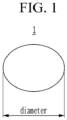
- the "diameter" of the "three-dimensional structured particle” may represent a length of a straight line passing through the center of the particle and having the longest extension, as shown in FIG. 1 . A length of the three-dimensional structured particles may be at most 2 times as large as its diameter.
- a length of the wire-type particles is at least 5 times as large as its diameter, in particular 10 times as large as its fiber diameter.
- the "wire-type particle” is a fiber having a length that is at least 5 times as large as its fiber diameter, in particular 10 times as large as its fiber diameter.
- a “diameter” of the wire-type particle means an average (fiber) diameter and the “length” means an average (fiber) length.
- An exemplary wire-type particle (or fiber) is shown in FIG. 2 .
- the average (fiber) length and the average (fiber) diameter of the wire-type particles are each independently, the average length and the average diameter may be measured by scanning electronic microscope (SEM) analysis. "Thickness" may be measured through a thickness measuring device or a photograph taken with an optical microscope such as a scanning electron microscope.
- a separator for a rechargeable lithium battery includes a substrate and a heat resistant layer on at least one surface of the substrate; wherein the heat resistant layer may include heterogeneous particles having different shapes; a shutdown filler is under, inside, or on the heat resistant layer, or two or more thereof.
- the separator for a rechargeable lithium battery has excellent heat resistance at the operating temperature of the battery and has a function to stop the battery in the event of thermal runaway of the battery, thereby contributing safe operation of a high-capacity and high-output rechargeable lithium battery.
- the separator for a rechargeable lithium battery of an embodiment includes a heat resistant layer, and the heat resistant layer includes heterogeneous particles having different shapes.
- the heat resistant layer may include three-dimensional structured particles and wire-type particles as heterogeneous particles having different shapes.
- the packing density of the coating layer is improved compared to the case where the three-dimensional structured particles alone are coated on the substrate, so that excellent heat resistance can be exhibited even when the separator is formed thinly.
- a coating layer including heterogeneous particles having different shapes is proposed, and in particular, this coating layer is referred to as a "heat resistant layer" in that it contributes to the heat resistance of the separator.
- the separator for a rechargeable lithium battery of an embodiment includes a shutdown filler in addition to the heat resistant layer.
- shutdown filler due to its function of the filler.
- the heat resistant layer may be on at least one surface of the substrate, and the shutdown filler may be under, inside, or on the heat resistant layer, or at least two of them.
- the heat resistant layer may include wire-type particles and three-dimensional structured particles as heterogeneous particles having different shapes.
- the three-dimensional structured particle may mean a particle having a three-dimensional (3D) shape
- the wire-type particle may mean a particle having a two-dimensional (2D) shape (or having the shape of a fiber).
- An average particle diameter (D50) of the three-dimensional structured particles may be 100 nm to 1,000 nm measured by laser diffraction.
- An average length of the wire-type particles may be 100 nm to 3 ⁇ m and an average diameter of the wire-type particles may be 1 nm to 100 nm, wherein the average length and the average diameter measured by scanning electronic microscope (SEM) analysis.
- a ratio of the average length of the wire-type particles and the average diameter of the three-dimensional structured particles may be 30:1 to 1:10.
- a ratio of the length of the wire-type particle and the diameter of the three-dimensional structured particle may be 20:1 to 1:10, or 10:1 to 1:5.
- the diameter of the three-dimensional structured particle may be 100 nm to 500 nm, 100 nm to 300 nm, or 200 nm to 300 nm.
- the length of the wire-type particle may be 100 nm to 1 ⁇ m, 100 nm to 0.5 ⁇ m, or 100 nm to 0.3 ⁇ m.
- the diameter of the wire-type particle may be 10 nm to 50 nm, and 20 nm to 30 nm.
- the wire-type particles efficiently fill empty spaces between the three-dimensional structured particles, and thus the packing density of the heat resistant layer can be remarkably improved.
- the coating uniformity may decrease, and as the length of the wire-type particle becomes shorter, the packing density may decrease. Considering this relationship, the ratio of the length of the wire-type particle and the diameter of the three-dimensional structured particle can be adjusted.
- a weight ratio of the wire-type particles and the three-dimensional structured particles may be 98:2 to 2:98, 90:10 to 10:90, 75:25 to 25:75, 60:40 to 40:60 or 50:50.
- the wire-type particles efficiently fill empty spaces between the three-dimensional structured particles, so that the packing density of the heat resistant layer can be remarkably improved.
- the weight of the wire-type particles increases relative to the weight of the three-dimensional structured particles, dispersibility decreases, and as the weight decreases, the heat resistance effect may decrease. Considering this relationship, the weight ratio of the wire-type particles and the three-dimensional structured particles can be adjusted.
- the three-dimensional structured particles are particles having a three-dimensional (3D) shape, and may have, for example, a spherical shape, an elliptical shape, or a polyhedron shape
- the three-dimensional structured particles may include an organic filler, an inorganic filler, or a combination thereof.
- the organic filler maintains its particle shape even after a thermal compression process, thereby contributing to the heat resistance of the separator.
- a weight average molecular weight of the organic filler may be 10,000 g/mol to 1,000,000 g/mol. Within the above range, it can contribute to the heat resistance and insulation resistance of the separator.
- the weight average molecular weight of the organic filler may be 10,000 g/mol or more, 50,000 g/mol or more, or 100,000 g/mol or more, and 1,000,000 g/mol or less, 600,000 g/mol or less, or 350,000 g/mol or less.
- the organic filler may include a crosslinked acrylate-based copolymer, a poly(vinylidene fluoride, PVdF)-based copolymer, a styrene-acrylate-based copolymer, an acrylic acid-based copolymer, or a combination thereof.
- the organic filler may be a crosslinked acrylate-based copolymer, which maintains the particle shape after the thermal compression process and improves the heat resistance of the separator.
- the inorganic filler is a material contributing to the heat resistance of the separator, and may include Al 2 O 3 , boehmite, B 2 O 3 , Ga 2 O 3 , TiO 2 , SnO 2 , CeO 2 , MgO, NiO, CaO, GaO, ZnO, ZrO 2 , Y 2 O 3 , SrTiOs, BaTiO 3 , Mg(OH) 2 , or a combination thereof.
- the inorganic filler may be Al 2 O 3 or boehmite.
- the wire-type particles are particles having a two-dimensional (2D) shape, and have a shape that is advantageous for the wire-type particles to efficiently fill empty spaces between the three-dimensional structured particles.
- the wire-type particles are fibers.
- the wire-type particles may include (fibrillar) boehmite, carbon nanotubes, silver nanowires, boron carbide nanowires, nanocellulose, copper hydroxide nanowires, silicon monoxide nanowires, hydroxyapatite nanowires, or a combination thereof.
- the wire-type particles may be (fibrillar) boehmite.
- the heat resistant layer may further include a binder for the heat resistant layer to bind particles constituting the heat resistant layer to the substrate.
- the binder for the heat resistant layer may include polyvinylidene fluoride (PVdF), carboxylmethyl cellulose (CMC), polyvinylidene fluoride-hexafluoropropylene (PVdF-HFP) copolymer, ethylene vinylacetate (EVA), hydroxyethyl cellulose (HEC), polyvinyl alcohol (PVA), polyvinylbutyral (PVB), an ethylene-acrylic acid copolymer, acrylonitrile, a vinyl acetate derivative, polyethylene glycol, an acrylic rubber, or a combination thereof.
- PVdF polyvinylidene fluoride
- CMC carboxylmethyl cellulose
- PVdF-HFP polyvinylidene fluoride-hexafluoropropylene copolymer
- EVA ethylene vinylacetate
- HEC hydroxyethyl cellulose
- PVVA polyvinyl alcohol
- PVB polyvinylbutyral
- the binder for the heat resistant layer may be of a solution type, which may exhibit excellent heat resistance compared to a particle type binder.
- a weight ratio of a total weight of the heterogeneous particles constituting the heat resistant layer and a weight of the adhesive binder for the heat resistant layer may be 10:1 to 50:1. Within the above range, while securing an adhesive strength between the particles constituting the heat resistant layer and an adhesive strength between the particles constituting the heat resistant layer and the substrate, heat resistance by the particles constituting the heat resistant layer and the binder for the heat resistant layer may be sufficiently exhibited.
- the weight ratio of the heterogeneous particles and the binder constituting the heat resistant layer may be adjusted.
- the heat resistant layer may have a thickness of less than or equal to 5 ⁇ m (however, greater than 0 ⁇ m). Since the heat resistant layer includes wire-type particles together with three-dimensionally structured particles as heterogeneous particles having different shapes, it can have sufficient heat resistance even with a thin thickness as described above.
- the heat resistant layer may have a thickness of 0.5 ⁇ m to 5 ⁇ m, 1 ⁇ m to 3 ⁇ m, or 1 ⁇ m to 2 ⁇ m. If the thickness of the heat resistant layer is within the above range, heat resistance is improved, suppressing internal short circuit of the battery, securing a stable separator, and suppressing an increase in internal resistance of the battery.
- the shutdown filler may be selected from material having a glass transition temperature (Tg) of 90 °C to 110 °C to stop operation of a battery during the thermal runaway of the battery.
- Tg glass transition temperature
- the shutdown filler may have an average diameter (D50) of 0.1 ⁇ m to 1 ⁇ m, 0.1 ⁇ m to 0.5 ⁇ m, or 0.1 ⁇ m to 0.3 ⁇ m measured by laser diffraction.
- D50 average diameter
- Such a shutdown filler may include the shutdown filler includes low-density polyethylene (LDPE), linear low-density polyethylene (LLDPE), low Mw high-density polyethylene (Low Mw-HDPE), or a combination thereof.
- LDPE low-density polyethylene
- LLDPE linear low-density polyethylene
- Low Mw-HDPE low Mw high-density polyethylene
- the shutdown filler may be low-density polyethylene.
- the shutdown filler may be disposed under, inside, or on the heat resistant layer or at least two thereof.
- the shutdown filler when it is disposed under and/or inside the heat resistant layer, it may be present as one layer, which is called to be a "shutdown filler layer.”
- the shutdown filler layer may have a thickness of less than or equal to 3 ⁇ m (however, greater than 0 ⁇ m). Such a thin thickness may secure a sufficient shutdown function.
- the shutdown filler layer has a thickness of 0.5 ⁇ m to 3 ⁇ m, 0.5 ⁇ m to 2 ⁇ m, or 1 ⁇ m to 2 ⁇ m.
- the shutdown filler layer may stop operation of a battery during the thermal runaway due to the excellent shutdown function.
- the substrate may include polyolefin, polyester, polytetrafluoroethylene (PTFE), polyacetal, polyamide, polyimide, polycarbonate, polyetheretherketone, polyaryletherketone, polyetherimide, polyamideimide, polybenzimidazole, polyethersulfone, polyphenylene oxide, a cyclic olefin copolymer, polyphenylene sulfide, polyethylene naphthalene, a glass fiber, or a combination thereof, but is not limited thereto.
- PTFE polytetrafluoroethylene
- polystyrene resin examples include polyethylene and polypropylene
- polyester examples include polyethylene terephthalate and polybutylene terephthalate.
- the substrate may be a non-woven fabric or a porous substrate in the form of a woven fabric, and may have a single film or multi-layer structure.
- the substrate may include a polyethylene single film, a polypropylene single film, a polyethylene/polypropylene double film, a polypropylene/polyethylene/polypropylene triple film, a polyethylene/polypropylene/polyethylene triple film, and the like.
- the substrate may have a thickness of 1 to 40 ⁇ m, for example, 1 to 30 ⁇ m, 1 to 20 ⁇ m, 5 to 15 ⁇ m, or 5 to 10 ⁇ m. If the thickness of the substrate is within the above range, a short circuit between the positive electrode and the negative electrode can be prevented without increasing the internal resistance of the battery.
- the separator of one embodiment has a structure in which the heat resistant layer is disposed on at least one surface of the substrate, wherein the shutdown filler is disposed under, inside, or on the heat resistant layer or at least two thereof.
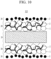
- the first heat resistant layer 20 is on the first surface of the substrate 10; and the first shutdown filler 3 may be under, inside, or on the first heat resistant layer 20 or at least two thereof.
- the heat resistant layer 20 may be on one surface of the substrate 10, and the shutdown filler 3 also may be present only on one surface of the substrate 10.
- the shutdown filler 3 when the shutdown filler 3 is present under and/or inside the heat resistant layer, it may be present as one layer (shutdown filler layer 30).
- the first heat resistant layer 20 is disposed; the first shutdown filler 3 is present under, inside, or on the first heat resistant layer 20 or at least two thereof; and a second shutdown filler 3 may be present on the second surface of the substrate 10.
- the heat resistant layer 20 may be disposed only on one surface of the substrate 10, and the shutdown filler 3 may be present on both surfaces of the substrate 10.
- the first heat resistant layer 20 is disposed on the first surface of the substrate 10; a second heat resistant layer 20 is disposed on the second surface of the substrate 10; the first shutdown filler 3 is present under, inside, or on the first heat resistant layer 20 or at least two thereof; and the second shutdown filler 3 may be present under, inside, or on the second heat resistant layer 20 or at least two thereof.
- the heat resistant layer 20 is disposed on both surfaces of the substrate 10, and the shutdown filler 3 also may be present on one surface or both surfaces of the substrate 10.
- the case that the shutdown filler is present only one of under, inside, or on the heat resistant layer is illustrated, but the shutdown filler may be present under, inside, or on the heat resistant layer or at least two thereof.
- the separator of an embodiment can exhibit excellent heat resistance even with a thin thickness.
- the separator may have an average thermal shrinkage rate of 5% or less, for example, 4% or less, 3% or less, 2% or less, or 1 % or less in a longitudinal direction (MD direction, Machine Direction) and a transverse direction (TD direction) measured after exposure at 150 to 250 °C for 1 hour. Accordingly, the separator of an embodiment can prevent shrinkage of the substrate due to heat and separation between the coating layer and the substrate.
- MD direction Machine Direction
- TD direction transverse direction
- a method of measuring the thermal shrinkage rate of the separator is not particularly limited but may be any commonly-used method in the technical field of the present invention.
- Non-limiting examples of the method of measuring the thermal shrinkage rate of the separator are as follow: performed by cutting the manufactured separator to have a size of a width (MD) of about 10 cm X a length (TD) of about 10 cm, storing it in a 150°C to 250 °C chamber for 1 hour, and then, measuring shrinkage degrees in a machine direction (MD) and a perpendicular direction (TD) to calculate the thermal shrinkage rate.
- Another embodiment provides a rechargeable lithium battery including the aforementioned separator for a rechargeable lithium battery of an embodiment.
- the aforementioned separator for a rechargeable lithium battery of an embodiment exhibits excellent thermal stability, structural stability, adhesive strength, air permeability, etc., and contributes to the stable operation of a rechargeable lithium battery.
- FIG. 11 is an exploded perspective view of a rechargeable lithium battery according to an embodiment.
- a rechargeable lithium battery 100 includes a battery cell including a negative electrode 112, a positive electrode 114 facing the negative electrode 112, a separator 113 disposed between the negative electrode 112 and the positive electrode 114, and an electrolyte solution (not shown) immersed in the negative electrode 112, positive electrode 114 and separator 113, a battery case 120 housing the battery cell, and a sealing member 140 sealing the battery case 120.
- the positive electrode 114 includes a positive electrode current collector and a positive electrode active material layer formed on the positive electrode current collector.
- the positive electrode active material layer includes a positive electrode active material, a positive electrode binder, and optionally a conductive material.
- the positive electrode current collector may use aluminum, nickel, and the like, but is not limited thereto.
- the positive electrode active material may use a compound capable of intercalating and deintercalating lithium.
- a composite oxide or a composite phosphate of a metal selected from cobalt, manganese, nickel, aluminum, iron, or a combination thereof and lithium may be used.
- the positive electrode active material may be a lithium cobalt oxide, a lithium nickel oxide, a lithium manganese oxide, a lithium nickel cobalt manganese oxide, a lithium nickel cobalt aluminum oxide, a lithium iron phosphate, or a combination thereof.
- the binder improves binding properties of positive electrode active material particles with one another and with a current collector
- specific examples may be polyvinyl alcohol, carboxylmethyl cellulose, hydroxypropyl cellulose, diacetyl cellulose, polyvinylchloride, carboxylated polyvinylchloride, polyvinylfluoride, an ethylene oxide-containing polymer, polyvinylpyrrolidone, polyurethane, polytetrafluoroethylene, polyvinylidene fluoride, polyethylene, polypropylene, a styrene-butadiene rubber, an acrylated styrene-butadiene rubber, an epoxy resin, nylon, and the like, but are not limited thereto. These may be used alone or as a mixture of two or more.
- the conductive material improves conductivity of an electrode and examples thereof may be natural graphite, artificial graphite, carbon black, a carbon fiber, a metal powder, a metal fiber, and the like, but are not limited thereto. These may be used alone or as a mixture of two or more.
- the metal powder and the metal fiber may use a metal of copper, nickel, aluminum, silver, and the like.
- the negative electrode 112 includes a negative electrode current collector and a negative electrode active material layer formed on the negative electrode current collector.
- the negative electrode current collector may use copper, gold, nickel, a copper alloy, and the like, but is not limited thereto.
- the negative electrode active material layer may include a negative electrode active material, a negative electrode binder, and optionally a conductive material.
- the negative electrode active material may be a material that reversibly intercalates/deintercalates lithium ions, a lithium metal, a lithium metal alloy, a material capable of doping and dedoping lithium, a transition metal oxide, or a combination thereof.
- the material that reversibly intercalates/deintercalates lithium ions may be a carbon material which is any generally-used carbon-based negative electrode active material, and examples thereof may be crystalline carbon, amorphous carbon, or a combination thereof.
- the crystalline carbon may be graphite such as irregular, sheet-shape, flake, spherical shape or fiber-shaped natural graphite or artificial graphite.
- the amorphous carbon may be soft carbon or hard carbon, a mesophase pitch carbonized product, calcined coke, and the like.
- the lithium metal alloy may be an alloy of lithium and a metal selected from Na, K, Rb, Cs, Fr, Be, Mg, Ca, Sr, Si, Sb, Pb, In, Zn, Ba, Ra, Ge, Al, and Sn.
- the material capable of doping and dedoping lithium may be Si, SiO x (0 ⁇ x ⁇ 2), a Si-C composite, a Si-Y alloy, Sn, SnO 2 , a Sn-C composite, a Sn-Y alloy, and the like, and at least one of these may be mixed with SiO 2 .
- the element Y may be selected from Mg, Ca, Sr, Ba, Ra, Sc, Y, Ti, Zr, Hf, Rf, V, Nb, Ta, Db, Cr, Mo, W, Sg, Tc, Re, Bh, Fe, Pb, Ru, Os, Hs, Rh, Ir, Pd, Pt, Cu, Ag, Au, Zn, Cd, B, Al, Ga, Sn, In, TI, Ge, P, As, Sb, Bi, S, Se, Te, Po, and a combination thereof.
- the transition metal oxide may be vanadium oxide, lithium vanadium oxide, and the like.
- the binder and the conductive material used in the negative electrode 112 may be the same as the binder and the conductive material of the aforementioned positive electrode 114.
- the positive electrode 114 and the negative electrode 112 may be manufactured by mixing each active material composition including each active material and a binder, and optionally a conductive material in a solvent, and coating the active material composition on each current collector.
- the solvent may be N-methylpyrrolidone, and the like, but is not limited thereto.
- the electrode manufacturing method is well known, and thus is not described in detail in the present specification.
- the electrolyte solution includes an organic solvent a lithium salt.
- the organic solvent serves as a medium for transmitting ions taking part in the electrochemical reaction of a battery.
- the organic solvent may be a carbonate-based solvent, an ester-based solvent, an ether-based solvent, a ketone-based solvent, an alcohol-based solvent, and an aprotic solvent.
- the carbonate-based solvent may be dimethyl carbonate, diethyl carbonate, dipropyl carbonate, methylpropyl carbonate, ethylpropyl carbonate, methylethyl carbonate, ethylene carbonate, propylene carbonate, butylene carbonate, and the like
- the ester-based solvent may be methyl acetate, ethyl acetate, n-propyl acetate, 1,1-dimethylethyl acetate, methylpropionate, ethylpropionate, ⁇ -butyrolactone, decanolide, valerolactone, mevalonolactone, caprolactone, and the like.
- the ether-based solvent may be dibutyl ether, tetraglyme, diglyme, dimethoxyethane, 2-methyltetrahydrofuran, tetrahydrofuran, and the like, and the ketone-based solvent may be cyclohexanone, and the like.
- the alcohol-based solvent may be ethanol, isopropyl alcohol, and the like
- the aprotic solvent may be nitriles such as R-CN (R is a C2 to C20 linear, branched, or cyclic hydrocarbon group, a double bond, an aromatic ring, or an ether bond), and the like, amides such as dimethyl formamide, dioxolanes such as 1,3-dioxolane, sulfolanes, and the like.
- the organic solvent may be used alone or in a mixture of two or more, and if the organic solvent is used in a mixture of two or more, the mixture ratio may be controlled in accordance with a desirable cell performance.
- the lithium salt is dissolved in an organic solvent, supplies lithium ions in a battery, basically operates the rechargeable lithium battery, and improves lithium ion transportation between positive and negative electrodes therein.
- the lithium salt may include LiPF 6 , LiBF 4 , LiSbF 6 , LiAsF 6 , LiN(SO 3 C 2 F 5 ) 2 , LiN(CF 3 SO 2 ) 2 , LiC 4 F 9 SO 3 , LiClO 4 , LiAlO 2 , LiAlCl 4 , LiN(C x F 2x+1 SO 2 )(C y F 2y+1 SO 2 ) (x and y are natural numbers), LiCI, Lil, LiB(C 2 O 4 ) 2 , or a combination thereof, but are not limited thereto.
- the lithium salt may be used in a concentration ranging from 0.1 M to 2.0 M. If the lithium salt is included within the above concentration range, an electrolyte may have excellent performance and lithium ion mobility due to optimal conductivity and viscosity of the electrolyte solution.
- an irregular-shaped and crosslinked acrylate-based copolymer having a weight average molecular weight of 300,000 g/mol and an average diameter (D50) of 200 nm was prepared.
- a wire-type particle boehmite having an average length (50) of 1 ⁇ m and an average diameter (D50) of 30 nm was prepared.
- the organic filler and the wire-type particle were mixed in a weight ratio of 20:80, preparing a composition for a coating layer according to Reference Example 1.
- polyethylene with a thickness of 9 ⁇ m (Manufacturer: SKIET Co., Ltd.) was prepared.
- the composition for a coating layer was coated on one surface of the substrate by using a Doctor blade and dried at room temperature to form a 3 ⁇ m-thick coating layer. Accordingly, a separator of Reference Example 1 was obtained.
- an irregular-shaped and crosslinked acrylate-based copolymer having a weight average molecular weight of 300,000 g/mol and a diameter of 200 nm was prepared.
- wire-type particles boehmite having a length of 0.5 ⁇ m and a diameter of 30 nm was prepared.
- a composition for a coating layer and a separator according to Reference Example 2 were prepared in the same manner as in Reference Example 1 except that the above organic filler and wire-type particles were used.
- an irregular-shaped and crosslinked acrylate-based copolymer having a weight average molecular weight of 300,000 g/mol and a diameter of 200 nm was prepared.
- wire-type particles boehmite having a length of 0.3 ⁇ m and a diameter of 30 nm was prepared.
- a composition for a coating layer and a separator according to Reference Example 3 were prepared in the same manner as in Reference Example 1 except that the above organic filler and wire-type particles were used.
- an irregular-shaped and crosslinked acrylate-based copolymer having a weight average molecular weight of 300,000 g/mol and a diameter of 500 nm was prepared.
- wire-type particles boehmite having a length of 0.3 ⁇ m and a diameter of 30 nm was prepared.
- a composition for a coating layer and a separator according to Reference Example 4 were prepared in the same manner as in Reference Example 1 except that the above organic filler and wire-type particles were used.
- an irregular-shaped and crosslinked acrylate-based copolymer having a weight average molecular weight of 300,000 g/mol and a diameter of 100 nm was prepared.
- wire-type particles boehmite having a length of 0.3 ⁇ m and a diameter of 30 nm was prepared.
- a composition for a coating layer and a separator according to Reference Example 5 were prepared in the same manner as in Reference Example 1 except that the above organic filler and wire-type particles were used.
- the same acrylate-based copolymer as in Reference Example 3 was prepared.
- amorphous alumina (Al 2 O 3 ) with a diameter of 100 nm was prepared as an inorganic filler.
- the same boehmite as in Reference Example 3 was prepared.
- a composition for a coating layer according to Reference Example 6 was prepared by mixing the organic filler, the inorganic filler, and the wire-type particles in a weight ratio of 10:10:80 in water as a solvent.
- a separator according to Example 6 were prepared in the same manner as in Reference Example 1 except that the above composition for the coating layer was used.
- amorphous alumina having a diameter of 300 nm was used as an inorganic filler among three-dimensional structured particles.
- a composition for a coating layer and a separator according to Reference Example 7 were prepared in the same manner as in Reference Example 6 except that the above inorganic filler was used.
- amorphous alumina having a diameter of 600 nm was used as an inorganic filler among three-dimensional structured particles.
- a composition for a coating layer and a separator according to Reference Example 8 were prepared in the same manner as in Reference Example 6 except that the above inorganic filler was used.
- amorphous alumina having a diameter of 800 nm was used as an inorganic filler among three-dimensional structured particles.
- a composition for a coating layer and a separator according to Reference Example 9 were prepared in the same manner as in Reference Example 6 except that the above inorganic filler was used.
- amorphous alumina having a diameter of 1,000 nm was used as an inorganic filler among three-dimensional structured particles.
- a composition for a coating layer and a separator according to Reference Example 10 were prepared in the same manner as in Reference Example 6 except that the above inorganic filler was used.
- a composition for a coating layer and a separator according to Comparative Reference Example 1 were prepared in the same manner as in Reference Example 3 except that no wire-type particles were used.
- a composition for a coating layer and a separator according to Comparative Reference Example 2 were prepared in the same manner as in Reference Example 3 except that no organic filler was used.
- SBR styrene butadiene rubber
- a composition for a coating layer and a separator according to Comparative Reference Example 3 were prepared in the same manner as in Reference Example 3 except that the above styrene butadiene rubber (SBR) and wire-type particles were used.
- SBR styrene butadiene rubber
- a composition for a coating layer and a separator according to Comparative Reference Example 4 were prepared in the same manner as in Reference Example 8 except that no wire-type particles were used.
- SBR styrene butadiene rubber
- a composition for a coating layer and a separator according to Comparative Reference Example 5 were prepared in the same manner as in Reference Example 8 except that the above styrene butadiene rubber (SBR) was used and no wire-type particles were used.
- SBR styrene butadiene rubber
- wire-type particles and the three-dimensional structured particles according to Reference Examples 1 to 10 and Comparative Reference Examples 1 to 5 are summarized in Table 1.
- Table 1 Wire-type particle Three-dimensional structured particle Organic filler Inorganic filler length (nm) weight (parts by weight) diameter (nm) weight (parts by weight) diamet er (nm) weight (parts by weight) Ref. Ex. 1 1,000 80 200 20 (unused) Ref. Ex. 2 500 200 Ref. Ex. 3 300 200 Ref. Ex. 4 300 500 Ref. Ex. 5 300 100 Comp. Ref. Ex. 1 (unused) 200 100 Comp. Ref. Ex. 2 300 100 (unused) Comp. Ref. Ex. 3 300 100 (organic adhesive was used) Ref. Ex.
- the separator After attaching a tape with a width of 12 mm and a length of 150 mm onto the coating layer of each of the separators, the separator was uniformly pressed with a hand roller. The separator was cut into a size extended by 2.0 mm each based on the length and width of the tape, preparing a sample.
- the tape-adhered side was peeled off by pulling in a 180 ° direction by using UTM (Instron Corp.).
- UTM Instron Corp.
- the peeling was performed at 20 mm/min, and a force required for 40 mm peeling was three times measured and averaged. The measurement results are shown in Table 2.
- Each separator of Reference Examples 1 to 10 and Comparative Reference Examples 1 to 5 was cut into a size of a width (MD) of about 10 cm ⁇ a length (TD) of about 10 cm, stored in a 200 °C chamber for 10 minutes, and then, measured with respect to shrinkage rates of the separator in the MD direction and the TD direction, and the results are shown in Table 2.
- the separators of Reference Examples 1 to 10 secured an appropriate adhesive strength as well as exhibited excellent heat resistance, compared with Comparative Reference Examples 1 to 5.
- one side of a substrate was coated by mixing an organic filler as three-dimensional structured particles and wire-type particles.
- each separator of Comparative Reference Examples 1 to 3 was prepared by excluding the wire-type particles or replacing the organic filler with an organic adhesive.
- one side of a substrate was coated by mixing an organic filler and an inorganic filler as three-dimensional structured particles with wire-type particles.
- each separator of Comparative Reference Examples 4 and 5 was prepared by excluding the wire-type particles or replacing the organic filler with an organic adhesive without using the wire-type particles.
- the separators of Reference Examples 1 to 5 exhibited equivalent thermal shrinkage rate and adhesive strength to those of Reference Examples 6 to 10. Accordingly, as long as one surface of a substrate was coated by mixing the three-dimensional structured particles and wire-type particles, excellent heat resistance was not only achieved, but also an appropriate adhesive strength was secured.
- organic fillers, inorganic fillers, or a combination thereof as the three-dimensional structured particles can be used to exhibit excellent heat resistance.
- an irregular-shaped and crosslinked acrylate-based copolymer (PMMA) having a weight average molecular weight of 300,000 g/mol and an average diameter (D50) of 200 nm was prepared.
- PMMA acrylate-based copolymer
- wire-type particles boehmite having an average length of 0.3 ⁇ m and an average diameter of 30 nm, wherein the average length and the average diameter was prepared.
- irregular-shaped low-density polyethylene having an average diameter (D50) of 500 nm was prepared.
- the organic filler, the wire-type particles, and the shutdown filler were mixed in a weight ratio of 20:60:20 to prepare A composition for a heat resistant layer including the shutdown filler of Preparation Example 1.
- a composition for a heat resistant layer was prepared by using the same organic filler and wire-type particles as in Preparation Example 1 without using the shutdown filler.
- the organic filler and the wire-type particles in a weight ratio of 20:80 were mixed in water as a solvent, preparing the composition for a heat resistant layer of Preparation Example 2. This is substantially the same as the composition for a coating layer of Reference Example 3.
- a composition for a heat resistant layer was prepared by using the same organic filler as in Preparation Example without using the shutdown filler.
- the organic filler was dispersed in water as a solvent, preparing the composition for a heat resistant layer of Preparation Example 2. This is substantially the same as the composition for a coating layer of Comparative Reference Example 1.
- a composition for a shutdown filler layer was prepared by using the same shutdown filler as in Preparation Example 1.
- styrene butadiene rubber 100 parts by weight of the shutdown filler and 30 parts by weight of a styrene butadiene rubber (SBR) as a binder were mixed in water as a solvent, preparing the composition for a shutdown filler layer.
- the above part by weight was based on 100 parts by weight of a total amount of solids included in the composition for a heat resistant layer of Preparation Example 1. This will be equally applied hereinafter.
- a composition for shutdown filler layer was prepared in the same manner as in Preparation Example 4 except that the content of the shutdown filler was changed into 130 parts by weight.
- a composition for shutdown filler layer was prepared in the same manner as in Preparation Example 4 except that the content of the shutdown filler was changed into 160 parts by weight.
- a composition for shutdown filler layer was prepared in the same manner as in Preparation Example 4 except that the content of the shutdown filler was changed into 200 parts by weight.
- a composition for shutdown filler layer was prepared in the same manner as in Preparation Example 4 except that the content of the shutdown filler was changed into 500 parts by weight.
- Example 1 Preparation of separator having [(substrate)/(heat resistant layer including shutdown filler)] structure and rechargeable lithium battery including the same
- polyethylene with a thickness of 9 ⁇ m (Manufacturer: SKIET Co., Ltd.) was prepared.
- Preparation Example 1 The composition of Preparation Example 1 was coated on one surface of the substrate by using a Doctor blade and dried at room temperature, forming a heat resistant layer including the shutdown filler (thickness after drying: 3 ⁇ m).
- LiCoO 2 as a positive electrode active material, polyvinylidene fluoride as a binder (tradename: KF1100), and denkablack as a conductive material were mixed in a weight ratio of 92.5:3.5:4, and this mixture was added to an N-Methyl-2-pyrrolidone solvent to a solid content of about 30 wt%, preparing positive electrode mixture slurry.
- the positive electrode mixture slurry was coated on an aluminum foil (Al foil, thickness: 15 ⁇ m) as a positive electrode current collector by using a Doctor blade and roll-pressed, manufacturing a positive electrode.
- the positive electrode had a loading amount of about 14.6 mg/cm 2 and rolling density of about 3.1 g/cm 3 .
- the positive electrode was wound into a circular shape with a diameter of 12 mm and then, used with a lithium metal as a counter electrode and the separator of Example 1, manufacturing a 2032-type rechargeable lithium battery cell (coin half-cell).
- an electrolyte solution was prepared by mixing ethylenecarbonate, diethylenecarbonate, and fluoroethylenecarbonate in a weight ratio of 2:6:2 and dissolving 1.3 M LiPF 6 in the mixed solvent.
- Example 2 Preparation of separator having [substrate/heat resistant layer/shutdown filler layer] structure and rechargeable lithium battery including the same
- Preparation Example 2 The composition of Preparation Example 2 was coated on one surface of the same substrate as in Example 1 by using the Doctor blade and dried at room temperature, forming a heat resistant layer (thickness for drying: 3 ⁇ m).
- the composition of Preparation Example 4 was coated by using the Doctor blade and dried at room temperature, forming a shutdown filler layer (thickness after drying: 0.5 ⁇ m).
- a rechargeable lithium battery cell was manufactured in the same manner as in Example 1 except that the separator of Example 2 was used.
- Example 3 Preparation of separator having [heat resistant layer/substrate/heat resistant layer/shutdown filler layer] structure and rechargeable lithium battery including the same
- Preparation Example 2 The composition of Preparation Example 2 was coated on both surfaces (first and second surfaces) of the same substrate as in Example 1 by using the Doctor blade and dried at room temperature, forming a heat resistant layer (thickness after drying: at one side:
- the composition of Preparation Example 4 was coated by using the Doctor blade and dried at room temperature, forming a shutdown filler layer (thickness after drying: 0.5 ⁇ m).
- a rechargeable lithium battery cell was manufactured in the same manner as in Example 1 except that the separator of Example 3 was used.
- Example 4 Preparation of separator having [shutdown filler layer/substrate/heat resistant layer/shutdown filler layer] structure and rechargeable lithium battery including the same
- the composition of Preparation Example 4 was coated by using the Doctor blade and dried at room temperature, forming a shutdown filler layer (thickness after drying: 0.5 ⁇ m).
- the composition of Preparation Example 2 was coated by using the Doctor blade and dried at room temperature, forming a heat resistant layer (thickness after drying: 3 ⁇ m).
- the composition of Preparation Example 4 was once coated again by using the Doctor blade and dried at room temperature, forming a shutdown filler layer (thickness after drying: 0.5 ⁇ m).
- a rechargeable lithium battery cell was manufactured in the same manner as in Example 1 except that the separator of Example 4 was used.
- Example 5 Preparation of separator having [shutdown filler layer/substrate/heat resistant layer/shutdown filler layer] structure and rechargeable lithium battery including the same
- a separator and a rechargeable lithium battery cell according to Example 5 were manufactured in the same manner as in Example 2 except that the composition of Preparation Example 5 was used instead of the composition of Preparation Example 4.
- Example 6 Preparation of separator having [shutdown filler layer/substrate/heat resistant layer/shutdown filler layer] and rechargeable lithium battery including the same
- a separator and a rechargeable lithium battery cell according to Example 6 were manufactured in the same manner as in Example 2 except that the composition of Preparation Example 6 was used instead of the composition of Preparation Example 4.
- Example 7 Preparation of separator having [shutdown filler layer/substrate/heat resistant layer/shutdown filler layer] structure and rechargeable lithium battery including the same
- a separator and a rechargeable lithium battery cell according to Example 7 were manufactured in the same manner as in Example 2 except that the composition of Preparation Example 7 was used instead of the composition of Preparation Example 4.
- Example 8 Preparation of separator having [shutdown filler layer/substrate/heat resistant layer/shutdown filler layer] structure and rechargeable lithium battery including the same
- a separator and a rechargeable lithium battery cell according to Example 8 were manufactured in the same manner as in Example 2 except that the composition of Preparation Example 8 was used instead of the composition of Preparation Example 4.
- Comparative Example 1 Preparation of separator having [substrate/heat resistant layer] structure and rechargeable lithium battery including the same
- a heat resistant layer was formed on a substrate in the same manner as in Example 2, which was obtained as a separator of Comparative Example 1.
- a rechargeable lithium battery cell was manufactured in the same manner as in Example 2 except that the separator of Comparative Example 1 was used.
- Comparative Example 2 Preparation of separator having [substrate/shutdown filler layer] structure and a rechargeable lithium battery including the same
- a shutdown filler layer was formed on a substrate in the same manner as in Example 3, which was obtained as a separator of Comparative Example 2.
- a rechargeable lithium battery cell was manufactured in the same manner as in Example 3 except that the separator of Comparative Example 2 was used.
- Comparative Example 3 Preparation of separator having [substrate/heat resistant layer (except three-dimensional structured particles)/shutdown filler layer] structure and rechargeable lithium battery including the same
- a separator and a rechargeable lithium battery cell according to Comparative Example 3 were manufactured in the same manner as in Example 2 except that the composition of Preparation Example 3 was used instead of the composition of Preparation Example 2.
- Example 3 Separator structure Heat resistant layer component Shutdown filler layer component
- Example 1 substrate/heat resistant layer including shutdown filler organic filler (three-dimensional structure), wire-type particles, shutdown filler - Example 2 substrate/heat resistant layer/shutdown filler layer organic filler (three-dimensional structure), wire-type particles shutdown filler Example 3 heat resistant layer/substrate/heat resistant layer/shutdown filler layer organic filler (three-dimensional structure), wire-type particles shutdown filler Examples 4 to 8 shutdown filler layer/substrate/heat resistant layer/shutdown filler layer organic filler (three-dimensional structure), wire-type particles shutdown filler Comparative Example 1 substrate/heat resistant layer organic filler (three-dimensional structure), wire-type particles - Comparative Example 2 substrate/shutdown filler layer - shutdown filler Comparative Example 3 substrate/heat resistant layer/shutdown filler layer organic filler (three-dimensional structure)
- the separators of Examples 1 to 8 exhibited excellent heat resistance and secured appropriate adhesive strength, compared with the separators of Comparative Examples 1 to 3.
- the separator of Example 1 was manufactured by forming a heat resistant layer on one surface (first surface) of a substrate, wherein the heat resistant layer particularly included an organic filler (three-dimensional structured particle), wire-type particles, and a shutdown filler. Based on the separator of Example 1, the shutdown filler was excluded from the separator of Comparative Example 1, and the organic filler (three-dimensional structured particle) and the wire-type particles were excluded from the separator of Comparative Example 2. Compared with the separator of Comparative Example 2, the separators of Comparative Example 1 and Example 1 exhibited improved heat resistance and adhesive strength.
- the separator of Example 2 was manufactured by sequentially forming a heat resistant layer and a shutdown filler layer on one surface (first surface) of a substrate
- the separator of Example 3 was manufactured by forming a heat resistant layer on the other surface (second surface) of a substrate, while sequentially forming the heat resistant layer and a shutdown filler layer on one surface (first surface) of the substrate.
- the separators of Examples 4 to 8 were manufactured by sequentially forming the heat resistant layer and a shutdown filler layer on one surface (first surface) of a substrate and also, forming a shutdown filler layer on the other surface (second surface) of the substrate.
- separators in which a heat resistant layer including an organic filler (three-dimensional structured particles) and wire-type particles was separately formed from a shutdown filler layer, exhibited somewhat improved heat resistance, compared with the separator of Example 1.
- the shutdown filler may be disposed anywhere under, inside, and on the heat resistant layer.
- the cells were evaluated with respect to a shutdown temperature by creating an exothermic situation, and the results are shown in Table 6.
- the shutdown temperature was obtained by averaging a temperature at an inflection point where internal resistance of the rechargeable lithium battery cells significantly increased.
- the rechargeable lithium battery cells of Examples 1 to 8 exhibited a longer life-span than those of Comparative Examples 1 to 3 but still secured appropriate initial formation efficiency. Furthermore, the rechargeable lithium battery cells of Examples 1 to 8 had an effect of lowering a shutdown temperature by introducing a shutdown filler into a separator and controlling its position and amount, etc. In particular, considering the results of Tables 4 and 5, the rechargeable lithium battery cells of Examples 1 to 8 additionally had a function of stopping operation of the battery cells during the thermal runaway as well as exhibited excellent heat resistance at the battery operating temperature, compared with the rechargeable lithium battery cells of Comparative Examples 1 to 3, contributing to safe operation of high-capacity and high-output rechargeable lithium batteries.
Landscapes
- Chemical & Material Sciences (AREA)
- Chemical Kinetics & Catalysis (AREA)
- Electrochemistry (AREA)
- General Chemical & Material Sciences (AREA)
- Engineering & Computer Science (AREA)
- Inorganic Chemistry (AREA)
- Manufacturing & Machinery (AREA)
- Materials Engineering (AREA)
- Composite Materials (AREA)
- Cell Separators (AREA)
Abstract
Disclosed are a separator for a rechargeable lithium battery and a rechargeable lithium battery including the same. For example, in an embodiment, the separator for a rechargeable lithium battery includes a substrate and a heat resistant layer on at least one surface of the substrate; wherein the heat resistant layer includes shutdown filler under, inside, or on the heat resistant layer, or two or more thereof.
Description
- A separator for a rechargeable lithium battery and a rechargeable lithium battery including the same are disclosed.
- Recently, rechargeable batteries have drawn attentions as an energy source. Among them, a rechargeable lithium battery having high energy density and discharge voltage has already been commercially available and widely used, but efforts to improve their performance are continuously being made.
- A separator, which is an element constituting the rechargeable lithium battery, enables charging and discharging the rechargeable lithium battery by continuously maintaining ionic conductivity, while separating positive and negative electrodes each other.
- In order to realize a high-capacity rechargeable lithium battery, it is necessary to reduce the thickness of a separator, which is a component that does not contribute to battery capacity. In addition, in order to enhance the safety of high-capacity and high-output rechargeable lithium batteries, there are needs for separators that not only have excellent heat resistance at an operating temperature of the battery, but also have a function to stop the battery in case of thermal runaway of the battery.
- The invention is defined by the appended claims. The description that follows is subjected to this limitation. Any disclosure lying outside the scope of said claims is only intended for illustrative as well as comparative purposes.
- It is an object of the present invention to provide a separator for a rechargeable lithium battery having excellent heat resistance at a battery operating temperature and an added function of stopping battery operation in case of thermal runaway of the battery.
- In an embodiment, a separator for a rechargeable lithium battery includes a substrate and a heat resistant layer on at least one surface of the substrate; wherein the separator further includes a shutdown filler under, inside, or on the heat resistant layer, or two or more thereof.
- Another embodiment provides a rechargeable lithium battery including the separator for a rechargeable lithium battery.
- The separator for a rechargeable lithium battery according to an embodiment has excellent heat resistance at the operating temperature of the battery and has a function to stop the battery in the event of thermal runaway of the battery, thereby contributing to safe driving of a high-capacity and high-output rechargeable lithium battery.
-
-
FIG. 1 is a view for explaining a "diameter" of the three-dimensional structuredparticle 1. -
FIG. 2 is a view for explaining a "diameter" and a "length" of the wire-type particle 2. -
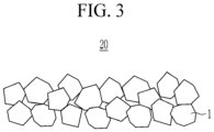
FIG. 3 is a view schematically showing that only the three-dimensionalstructured particles 1 are coated on a substrate (not shown). -
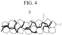
FIG. 4 is a view schematically showing that the three-dimensionalstructured particles 1 and the wire-type particles 2 are coated on a substrate (not shown). -
FIGS. 5 to 10 are views schematically illustrating separators for a rechargeable lithium battery according to embodiments, respectively. -
FIG. 11 is an exploded perspective view of a rechargeable lithium battery according to an embodiment. - Hereinafter, specific embodiments will be described in detail so that those of ordinary skill in the art can easily implement them.
- It should be understood that terms such as "comprises," "includes," or "have" are intended to designate the presence of an embodied feature, number, step, element, or a combination thereof, but it does not preclude the possibility of the presence or addition of one or more other features, number, step, element, or a combination thereof.
- In the drawings, the thickness of layers, films, panels, regions, etc., are exaggerated for clarity and like reference numerals designate like elements throughout the specification. It will be understood that when an element such as a layer, film, region, or substrate is referred to as being "on" another element, it can be directly on the other element or intervening elements may also be present. In contrast, when an element is referred to as being "directly on" another element, there are no intervening elements present.
- "Layer" herein includes not only a shape formed on the whole surface when viewed from a plan view, but also a shape formed on a partial surface.
- "Diameter" of the "three-dimensional structured particle" means an average particle diameter (D50) of the particles and may be measured by laser diffraction (LD). The method may be performed according to ISO 13320:2020. According to the IUPAC definition, the equivalent diameter of a non-spherical particle is equal to a diameter of a spherical particle that exhibits identical properties to that of the investigated non-spherical particle. For example, the "diameter" of the "three-dimensional structured particle" may represent a length of a straight line passing through the center of the particle and having the longest extension, as shown in
FIG. 1 . A length of the three-dimensional structured particles may be at most 2 times as large as its diameter. - A length of the wire-type particles is at least 5 times as large as its diameter, in particular 10 times as large as its fiber diameter. In other words, the "wire-type particle" is a fiber having a length that is at least 5 times as large as its fiber diameter, in particular 10 times as large as its fiber diameter. A "diameter" of the wire-type particle means an average (fiber) diameter and the "length" means an average (fiber) length. An exemplary wire-type particle (or fiber) is shown in
FIG. 2 . The average (fiber) length and the average (fiber) diameter of the wire-type particles are each independently, the average length and the average diameter may be measured by scanning electronic microscope (SEM) analysis. "Thickness" may be measured through a thickness measuring device or a photograph taken with an optical microscope such as a scanning electron microscope. - In an embodiment, a separator for a rechargeable lithium battery includes a substrate and a heat resistant layer on at least one surface of the substrate; wherein the heat resistant layer may include heterogeneous particles having different shapes; a shutdown filler is under, inside, or on the heat resistant layer, or two or more thereof.
- The separator for a rechargeable lithium battery according to an embodiment has excellent heat resistance at the operating temperature of the battery and has a function to stop the battery in the event of thermal runaway of the battery, thereby contributing safe operation of a high-capacity and high-output rechargeable lithium battery.
- For example, the separator for a rechargeable lithium battery of an embodiment includes a heat resistant layer, and the heat resistant layer includes heterogeneous particles having different shapes. For example, the heat resistant layer may include three-dimensional structured particles and wire-type particles as heterogeneous particles having different shapes.
- As shown in
FIG. 3 , when three-dimensionalstructured particles 1 alone are coated on a substrate (not shown), a plurality of empty spaces are created between the three-dimensionalstructured particles 1, which lowers packing density of a coating layer and eventually, deteriorates heat resistance of the separator. - However, as shown in
FIG. 4 , when the three-dimensionalstructured particles 1 are coated with wire-type particles 2 on the substrate (not shown), the plurality of empty spaces is filled with the wire-type particles 2, increasing the packing density and the improving the heat resistance of the separator. - If the particles having different shapes are coated on the substrate, the packing density of the coating layer is improved compared to the case where the three-dimensional structured particles alone are coated on the substrate, so that excellent heat resistance can be exhibited even when the separator is formed thinly.
- Accordingly, in the above embodiment, a coating layer including heterogeneous particles having different shapes is proposed, and in particular, this coating layer is referred to as a "heat resistant layer" in that it contributes to the heat resistance of the separator.
- Meanwhile, the separator for a rechargeable lithium battery of an embodiment includes a shutdown filler in addition to the heat resistant layer.
- As driving cycles of the high-capacity and high-output rechargeable lithium battery are repeated, the temperature of the battery increases and extreme situations such as thermal runaway may occur.
- Accordingly, in the above embodiment, when thermal runaway of the battery occurs, a filler capable of stopping the driving of the battery is introduced, and in particular, the filler is referred to as a "shutdown filler" due to its function of the filler.
- Considering the respective functions of the heat resistant layer and the shutdown filler, the heat resistant layer may be on at least one surface of the substrate, and the shutdown filler may be under, inside, or on the heat resistant layer, or at least two of them.
- Hereinafter, the separator for a rechargeable lithium battery of an embodiment will be described in detail.
- As described above, the heat resistant layer may include wire-type particles and three-dimensional structured particles as heterogeneous particles having different shapes. Herein, the three-dimensional structured particle may mean a particle having a three-dimensional (3D) shape, and the wire-type particle may mean a particle having a two-dimensional (2D) shape (or having the shape of a fiber).
- An average particle diameter (D50) of the three-dimensional structured particles may be 100 nm to 1,000 nm measured by laser diffraction. An average length of the wire-type particles may be 100 nm to 3 µm and an average diameter of the wire-type particles may be 1 nm to 100 nm, wherein the average length and the average diameter measured by scanning electronic microscope (SEM) analysis. A ratio of the average length of the wire-type particles and the average diameter of the three-dimensional structured particles may be 30:1 to 1:10.
- A ratio of the length of the wire-type particle and the diameter of the three-dimensional structured particle may be 20:1 to 1:10, or 10:1 to 1:5.
- For example, the diameter of the three-dimensional structured particle may be 100 nm to 500 nm, 100 nm to 300 nm, or 200 nm to 300 nm.
- Further, the length of the wire-type particle may be 100 nm to 1 µm, 100 nm to 0.5 µm, or 100 nm to 0.3 µm. In addition, the diameter of the wire-type particle may be 10 nm to 50 nm, and 20 nm to 30 nm.
- If each of the above ranges is satisfied, the wire-type particles efficiently fill empty spaces between the three-dimensional structured particles, and thus the packing density of the heat resistant layer can be remarkably improved. However, as the length of the wire-type particle is relatively longer compared to the diameter of the three-dimensional structured particle, the coating uniformity may decrease, and as the length of the wire-type particle becomes shorter, the packing density may decrease. Considering this relationship, the ratio of the length of the wire-type particle and the diameter of the three-dimensional structured particle can be adjusted.
- On the other hand, a weight ratio of the wire-type particles and the three-dimensional structured particles may be 98:2 to 2:98, 90:10 to 10:90, 75:25 to 25:75, 60:40 to 40:60 or 50:50.
- Within these ranges, the wire-type particles efficiently fill empty spaces between the three-dimensional structured particles, so that the packing density of the heat resistant layer can be remarkably improved. However, as the weight of the wire-type particles increases relative to the weight of the three-dimensional structured particles, dispersibility decreases, and as the weight decreases, the heat resistance effect may decrease. Considering this relationship, the weight ratio of the wire-type particles and the three-dimensional structured particles can be adjusted.
- The three-dimensional structured particles are particles having a three-dimensional (3D) shape, and may have, for example, a spherical shape, an elliptical shape, or a polyhedron shape
- For example, the three-dimensional structured particles may include an organic filler, an inorganic filler, or a combination thereof.
- The organic filler maintains its particle shape even after a thermal compression process, thereby contributing to the heat resistance of the separator.
- For example, a weight average molecular weight of the organic filler may be 10,000 g/mol to 1,000,000 g/mol. Within the above range, it can contribute to the heat resistance and insulation resistance of the separator. For example, the weight average molecular weight of the organic filler may be 10,000 g/mol or more, 50,000 g/mol or more, or 100,000 g/mol or more, and 1,000,000 g/mol or less, 600,000 g/mol or less, or 350,000 g/mol or less.
- For example, the organic filler may include a crosslinked acrylate-based copolymer, a poly(vinylidene fluoride, PVdF)-based copolymer, a styrene-acrylate-based copolymer, an acrylic acid-based copolymer, or a combination thereof. For example, the organic filler may be a crosslinked acrylate-based copolymer, which maintains the particle shape after the thermal compression process and improves the heat resistance of the separator.
- The inorganic filler is a material contributing to the heat resistance of the separator, and may include Al2O3, boehmite, B2O3, Ga2O3, TiO2, SnO2, CeO2, MgO, NiO, CaO, GaO, ZnO, ZrO2, Y2O3, SrTiOs, BaTiO3, Mg(OH)2, or a combination thereof. For example, the inorganic filler may be Al2O3 or boehmite.
- The wire-type particles are particles having a two-dimensional (2D) shape, and have a shape that is advantageous for the wire-type particles to efficiently fill empty spaces between the three-dimensional structured particles. The wire-type particles are fibers.
- The wire-type particles may include (fibrillar) boehmite, carbon nanotubes, silver nanowires, boron carbide nanowires, nanocellulose, copper hydroxide nanowires, silicon monoxide nanowires, hydroxyapatite nanowires, or a combination thereof. For example, the wire-type particles may be (fibrillar) boehmite.
- The heat resistant layer may further include a binder for the heat resistant layer to bind particles constituting the heat resistant layer to the substrate.
- The binder for the heat resistant layer may include polyvinylidene fluoride (PVdF), carboxylmethyl cellulose (CMC), polyvinylidene fluoride-hexafluoropropylene (PVdF-HFP) copolymer, ethylene vinylacetate (EVA), hydroxyethyl cellulose (HEC), polyvinyl alcohol (PVA), polyvinylbutyral (PVB), an ethylene-acrylic acid copolymer, acrylonitrile, a vinyl acetate derivative, polyethylene glycol, an acrylic rubber, or a combination thereof.
- The binder for the heat resistant layer may be of a solution type, which may exhibit excellent heat resistance compared to a particle type binder.
- A weight ratio of a total weight of the heterogeneous particles constituting the heat resistant layer and a weight of the adhesive binder for the heat resistant layer may be 10:1 to 50:1. Within the above range, while securing an adhesive strength between the particles constituting the heat resistant layer and an adhesive strength between the particles constituting the heat resistant layer and the substrate, heat resistance by the particles constituting the heat resistant layer and the binder for the heat resistant layer may be sufficiently exhibited.
- For example, as the content of the binder within the above range is relatively high, heat resistance may decrease, and as the content of the binder decreases, adhesive strength to the substrate may decrease. Considering such a trade-off relationship, the weight ratio of the heterogeneous particles and the binder constituting the heat resistant layer may be adjusted.
- The heat resistant layer may have a thickness of less than or equal to 5 µm (however, greater than 0 µm). Since the heat resistant layer includes wire-type particles together with three-dimensionally structured particles as heterogeneous particles having different shapes, it can have sufficient heat resistance even with a thin thickness as described above.
- The heat resistant layer may have a thickness of 0.5 µm to 5 µm, 1 µm to 3 µm, or 1 µm to 2 µm. If the thickness of the heat resistant layer is within the above range, heat resistance is improved, suppressing internal short circuit of the battery, securing a stable separator, and suppressing an increase in internal resistance of the battery.
- The shutdown filler may be selected from material having a glass transition temperature (Tg) of 90 °C to 110 °C to stop operation of a battery during the thermal runaway of the battery.
- The shutdown filler may have an average diameter (D50) of 0.1 µm to 1 µm, 0.1 µm to 0.5 µm, or 0.1 µm to 0.3 µm measured by laser diffraction.
- Such a shutdown filler may include the shutdown filler includes low-density polyethylene (LDPE), linear low-density polyethylene (LLDPE), low Mw high-density polyethylene (Low Mw-HDPE), or a combination thereof.
- For example, the shutdown filler may be low-density polyethylene.
- As mentioned above, the shutdown filler may be disposed under, inside, or on the heat resistant layer or at least two thereof. In particular, when the shutdown filler is disposed under and/or inside the heat resistant layer, it may be present as one layer, which is called to be a "shutdown filler layer."
- The shutdown filler layer may have a thickness of less than or equal to 3 µm (however, greater than 0 µm). Such a thin thickness may secure a sufficient shutdown function.
- For example, the shutdown filler layer has a thickness of 0.5 µm to 3 µm, 0.5 µm to 2 µm, or 1 µm to 2 µm. When the shutdown filler layer has a thickness within the ranges, the shutdown filler layer may stop operation of a battery during the thermal runaway due to the excellent shutdown function.
- The substrate may include polyolefin, polyester, polytetrafluoroethylene (PTFE), polyacetal, polyamide, polyimide, polycarbonate, polyetheretherketone, polyaryletherketone, polyetherimide, polyamideimide, polybenzimidazole, polyethersulfone, polyphenylene oxide, a cyclic olefin copolymer, polyphenylene sulfide, polyethylene naphthalene, a glass fiber, or a combination thereof, but is not limited thereto.
- Examples of the polyolefin include polyethylene and polypropylene, and examples of the polyester include polyethylene terephthalate and polybutylene terephthalate.
- In addition, the substrate may be a non-woven fabric or a porous substrate in the form of a woven fabric, and may have a single film or multi-layer structure. For example, the substrate may include a polyethylene single film, a polypropylene single film, a polyethylene/polypropylene double film, a polypropylene/polyethylene/polypropylene triple film, a polyethylene/polypropylene/polyethylene triple film, and the like.
- The substrate may have a thickness of 1 to 40 µm, for example, 1 to 30 µm, 1 to 20 µm, 5 to 15 µm, or 5 to 10 µm. If the thickness of the substrate is within the above range, a short circuit between the positive electrode and the negative electrode can be prevented without increasing the internal resistance of the battery.
- As shown in
FIGS. 5 to 10 , the separator of one embodiment has a structure in which the heat resistant layer is disposed on at least one surface of the substrate, wherein the shutdown filler is disposed under, inside, or on the heat resistant layer or at least two thereof. - For example, as shown in
FIGS. 5 to 7 , the first heatresistant layer 20 is on the first surface of thesubstrate 10; and thefirst shutdown filler 3 may be under, inside, or on the first heatresistant layer 20 or at least two thereof. In other words, the heatresistant layer 20 may be on one surface of thesubstrate 10, and theshutdown filler 3 also may be present only on one surface of thesubstrate 10. In particular, as shown inFIGS. 5 and7 , when theshutdown filler 3 is present under and/or inside the heat resistant layer, it may be present as one layer (shutdown filler layer 30). - On the other hand, as shown in
FIG. 8 , on the first surface of thesubstrate 10, the first heatresistant layer 20 is disposed; thefirst shutdown filler 3 is present under, inside, or on the first heatresistant layer 20 or at least two thereof; and asecond shutdown filler 3 may be present on the second surface of thesubstrate 10. In other words, the heatresistant layer 20 may be disposed only on one surface of thesubstrate 10, and theshutdown filler 3 may be present on both surfaces of thesubstrate 10. - Alternatively, as shown in
FIGS. 9 and10 , the first heatresistant layer 20 is disposed on the first surface of thesubstrate 10; a second heatresistant layer 20 is disposed on the second surface of thesubstrate 10; thefirst shutdown filler 3 is present under, inside, or on the first heatresistant layer 20 or at least two thereof; and thesecond shutdown filler 3 may be present under, inside, or on the second heatresistant layer 20 or at least two thereof. In other words, the heatresistant layer 20 is disposed on both surfaces of thesubstrate 10, and theshutdown filler 3 also may be present on one surface or both surfaces of thesubstrate 10. Herein, the case that the shutdown filler is present only one of under, inside, or on the heat resistant layer is illustrated, but the shutdown filler may be present under, inside, or on the heat resistant layer or at least two thereof. - As mentioned above, the separator of an embodiment can exhibit excellent heat resistance even with a thin thickness.
- For example, the separator may have an average thermal shrinkage rate of 5% or less, for example, 4% or less, 3% or less, 2% or less, or 1 % or less in a longitudinal direction (MD direction, Machine Direction) and a transverse direction (TD direction) measured after exposure at 150 to 250 °C for 1 hour. Accordingly, the separator of an embodiment can prevent shrinkage of the substrate due to heat and separation between the coating layer and the substrate.
- A method of measuring the thermal shrinkage rate of the separator is not particularly limited but may be any commonly-used method in the technical field of the present invention. Non-limiting examples of the method of measuring the thermal shrinkage rate of the separator are as follow: performed by cutting the manufactured separator to have a size of a width (MD) of about 10 cm X a length (TD) of about 10 cm, storing it in a 150°C to 250 °C chamber for 1 hour, and then, measuring shrinkage degrees in a machine direction (MD) and a perpendicular direction (TD) to calculate the thermal shrinkage rate.
- Another embodiment provides a rechargeable lithium battery including the aforementioned separator for a rechargeable lithium battery of an embodiment.
- The aforementioned separator for a rechargeable lithium battery of an embodiment exhibits excellent thermal stability, structural stability, adhesive strength, air permeability, etc., and contributes to the stable operation of a rechargeable lithium battery.
- Hereinafter, the rechargeable lithium battery will be described in detail, except for overlapping descriptions with the foregoing.
-
FIG. 11 is an exploded perspective view of a rechargeable lithium battery according to an embodiment. Referring toFIG. 11 , arechargeable lithium battery 100 according to an embodiment includes a battery cell including anegative electrode 112, apositive electrode 114 facing thenegative electrode 112, aseparator 113 disposed between thenegative electrode 112 and thepositive electrode 114, and an electrolyte solution (not shown) immersed in thenegative electrode 112,positive electrode 114 andseparator 113, abattery case 120 housing the battery cell, and a sealingmember 140 sealing thebattery case 120. - The
positive electrode 114 includes a positive electrode current collector and a positive electrode active material layer formed on the positive electrode current collector. The positive electrode active material layer includes a positive electrode active material, a positive electrode binder, and optionally a conductive material. - The positive electrode current collector may use aluminum, nickel, and the like, but is not limited thereto.
- The positive electrode active material may use a compound capable of intercalating and deintercalating lithium. For example, at least one of a composite oxide or a composite phosphate of a metal selected from cobalt, manganese, nickel, aluminum, iron, or a combination thereof and lithium may be used. For example, the positive electrode active material may be a lithium cobalt oxide, a lithium nickel oxide, a lithium manganese oxide, a lithium nickel cobalt manganese oxide, a lithium nickel cobalt aluminum oxide, a lithium iron phosphate, or a combination thereof.
- The binder improves binding properties of positive electrode active material particles with one another and with a current collector, and specific examples may be polyvinyl alcohol, carboxylmethyl cellulose, hydroxypropyl cellulose, diacetyl cellulose, polyvinylchloride, carboxylated polyvinylchloride, polyvinylfluoride, an ethylene oxide-containing polymer, polyvinylpyrrolidone, polyurethane, polytetrafluoroethylene, polyvinylidene fluoride, polyethylene, polypropylene, a styrene-butadiene rubber, an acrylated styrene-butadiene rubber, an epoxy resin, nylon, and the like, but are not limited thereto. These may be used alone or as a mixture of two or more.
- The conductive material improves conductivity of an electrode and examples thereof may be natural graphite, artificial graphite, carbon black, a carbon fiber, a metal powder, a metal fiber, and the like, but are not limited thereto. These may be used alone or as a mixture of two or more. The metal powder and the metal fiber may use a metal of copper, nickel, aluminum, silver, and the like.
- The
negative electrode 112 includes a negative electrode current collector and a negative electrode active material layer formed on the negative electrode current collector. - The negative electrode current collector may use copper, gold, nickel, a copper alloy, and the like, but is not limited thereto.
- The negative electrode active material layer may include a negative electrode active material, a negative electrode binder, and optionally a conductive material. The negative electrode active material may be a material that reversibly intercalates/deintercalates lithium ions, a lithium metal, a lithium metal alloy, a material capable of doping and dedoping lithium, a transition metal oxide, or a combination thereof.
- The material that reversibly intercalates/deintercalates lithium ions may be a carbon material which is any generally-used carbon-based negative electrode active material, and examples thereof may be crystalline carbon, amorphous carbon, or a combination thereof. Examples of the crystalline carbon may be graphite such as irregular, sheet-shape, flake, spherical shape or fiber-shaped natural graphite or artificial graphite. Examples of the amorphous carbon may be soft carbon or hard carbon, a mesophase pitch carbonized product, calcined coke, and the like. The lithium metal alloy may be an alloy of lithium and a metal selected from Na, K, Rb, Cs, Fr, Be, Mg, Ca, Sr, Si, Sb, Pb, In, Zn, Ba, Ra, Ge, Al, and Sn. The material capable of doping and dedoping lithium may be Si, SiOx (0<x<2), a Si-C composite, a Si-Y alloy, Sn, SnO2, a Sn-C composite, a Sn-Y alloy, and the like, and at least one of these may be mixed with SiO2. Specific examples of the element Y may be selected from Mg, Ca, Sr, Ba, Ra, Sc, Y, Ti, Zr, Hf, Rf, V, Nb, Ta, Db, Cr, Mo, W, Sg, Tc, Re, Bh, Fe, Pb, Ru, Os, Hs, Rh, Ir, Pd, Pt, Cu, Ag, Au, Zn, Cd, B, Al, Ga, Sn, In, TI, Ge, P, As, Sb, Bi, S, Se, Te, Po, and a combination thereof. The transition metal oxide may be vanadium oxide, lithium vanadium oxide, and the like.
- The binder and the conductive material used in the
negative electrode 112 may be the same as the binder and the conductive material of the aforementionedpositive electrode 114. - The
positive electrode 114 and thenegative electrode 112 may be manufactured by mixing each active material composition including each active material and a binder, and optionally a conductive material in a solvent, and coating the active material composition on each current collector. Herein, the solvent may be N-methylpyrrolidone, and the like, but is not limited thereto. The electrode manufacturing method is well known, and thus is not described in detail in the present specification. - The electrolyte solution includes an organic solvent a lithium salt.
- The organic solvent serves as a medium for transmitting ions taking part in the electrochemical reaction of a battery. The organic solvent may be a carbonate-based solvent, an ester-based solvent, an ether-based solvent, a ketone-based solvent, an alcohol-based solvent, and an aprotic solvent. The carbonate-based solvent may be dimethyl carbonate, diethyl carbonate, dipropyl carbonate, methylpropyl carbonate, ethylpropyl carbonate, methylethyl carbonate, ethylene carbonate, propylene carbonate, butylene carbonate, and the like, and the ester-based solvent may be methyl acetate, ethyl acetate, n-propyl acetate, 1,1-dimethylethyl acetate, methylpropionate, ethylpropionate, γ-butyrolactone, decanolide, valerolactone, mevalonolactone, caprolactone, and the like. The ether-based solvent may be dibutyl ether, tetraglyme, diglyme, dimethoxyethane, 2-methyltetrahydrofuran, tetrahydrofuran, and the like, and the ketone-based solvent may be cyclohexanone, and the like. The alcohol-based solvent may be ethanol, isopropyl alcohol, and the like, and the aprotic solvent may be nitriles such as R-CN (R is a C2 to C20 linear, branched, or cyclic hydrocarbon group, a double bond, an aromatic ring, or an ether bond), and the like, amides such as dimethyl formamide, dioxolanes such as 1,3-dioxolane, sulfolanes, and the like.
- The organic solvent may be used alone or in a mixture of two or more, and if the organic solvent is used in a mixture of two or more, the mixture ratio may be controlled in accordance with a desirable cell performance.
- The lithium salt is dissolved in an organic solvent, supplies lithium ions in a battery, basically operates the rechargeable lithium battery, and improves lithium ion transportation between positive and negative electrodes therein. Examples of the lithium salt may include LiPF6, LiBF4, LiSbF6, LiAsF6, LiN(SO3C2F5)2, LiN(CF3SO2)2, LiC4F9SO3, LiClO4, LiAlO2, LiAlCl4, LiN(CxF2x+1SO2)(CyF2y+1SO2) (x and y are natural numbers), LiCI, Lil, LiB(C2O4)2, or a combination thereof, but are not limited thereto.
- The lithium salt may be used in a concentration ranging from 0.1 M to 2.0 M. If the lithium salt is included within the above concentration range, an electrolyte may have excellent performance and lithium ion mobility due to optimal conductivity and viscosity of the electrolyte solution.
- Examples and comparative examples of the present invention are described below. The following examples are only examples of the present invention, but the present invention is not limited to the following examples.
- As an organic filler among three-dimensional structured particles, an irregular-shaped and crosslinked acrylate-based copolymer having a weight average molecular weight of 300,000 g/mol and an average diameter (D50) of 200 nm was prepared. In addition, as a wire-type particle, boehmite having an average length (50) of 1 µm and an average diameter (D50) of 30 nm was prepared.
- In water as a solvent, the organic filler and the wire-type particle were mixed in a weight ratio of 20:80, preparing a composition for a coating layer according to Reference Example 1.
- As a substrate, polyethylene with a thickness of 9 µm (Manufacturer: SKIET Co., Ltd.) was prepared.
- The composition for a coating layer was coated on one surface of the substrate by using a Doctor blade and dried at room temperature to form a 3 µm-thick coating layer. Accordingly, a separator of Reference Example 1 was obtained.
- As an organic filler among three-dimensional structured particles, an irregular-shaped and crosslinked acrylate-based copolymer having a weight average molecular weight of 300,000 g/mol and a diameter of 200 nm was prepared. In addition, as wire-type particles, boehmite having a length of 0.5 µm and a diameter of 30 nm was prepared.
- A composition for a coating layer and a separator according to Reference Example 2 were prepared in the same manner as in Reference Example 1 except that the above organic filler and wire-type particles were used.
- As an organic filler among three-dimensional structured particles, an irregular-shaped and crosslinked acrylate-based copolymer having a weight average molecular weight of 300,000 g/mol and a diameter of 200 nm was prepared. In addition, as wire-type particles, boehmite having a length of 0.3 µm and a diameter of 30 nm was prepared.
- A composition for a coating layer and a separator according to Reference Example 3 were prepared in the same manner as in Reference Example 1 except that the above organic filler and wire-type particles were used.
- As an organic filler among three-dimensional structured particles, an irregular-shaped and crosslinked acrylate-based copolymer having a weight average molecular weight of 300,000 g/mol and a diameter of 500 nm was prepared. In addition, as wire-type particles, boehmite having a length of 0.3 µm and a diameter of 30 nm was prepared.
- A composition for a coating layer and a separator according to Reference Example 4 were prepared in the same manner as in Reference Example 1 except that the above organic filler and wire-type particles were used.
- As an organic filler among three-dimensional structured particles, an irregular-shaped and crosslinked acrylate-based copolymer having a weight average molecular weight of 300,000 g/mol and a diameter of 100 nm was prepared. In addition, as wire-type particles, boehmite having a length of 0.3 µm and a diameter of 30 nm was prepared.
- A composition for a coating layer and a separator according to Reference Example 5 were prepared in the same manner as in Reference Example 1 except that the above organic filler and wire-type particles were used.
- As an organic filler among three-dimensional structured particles, the same acrylate-based copolymer as in Reference Example 3 was prepared. In addition, as wire-type particles, amorphous alumina (Al2O3) with a diameter of 100 nm was prepared as an inorganic filler. In addition, as wire-type particles, the same boehmite as in Reference Example 3 was prepared.
- A composition for a coating layer according to Reference Example 6 was prepared by mixing the organic filler, the inorganic filler, and the wire-type particles in a weight ratio of 10:10:80 in water as a solvent.
- A separator according to Example 6 were prepared in the same manner as in Reference Example 1 except that the above composition for the coating layer was used.
- As an inorganic filler among three-dimensional structured particles, amorphous alumina having a diameter of 300 nm was used. A composition for a coating layer and a separator according to Reference Example 7 were prepared in the same manner as in Reference Example 6 except that the above inorganic filler was used.
- As an inorganic filler among three-dimensional structured particles, amorphous alumina having a diameter of 600 nm was used. A composition for a coating layer and a separator according to Reference Example 8 were prepared in the same manner as in Reference Example 6 except that the above inorganic filler was used.
- As an inorganic filler among three-dimensional structured particles, amorphous alumina having a diameter of 800 nm was used. A composition for a coating layer and a separator according to Reference Example 9 were prepared in the same manner as in Reference Example 6 except that the above inorganic filler was used.
- As an inorganic filler among three-dimensional structured particles, amorphous alumina having a diameter of 1,000 nm was used. A composition for a coating layer and a separator according to Reference Example 10 were prepared in the same manner as in Reference Example 6 except that the above inorganic filler was used.
- A composition for a coating layer and a separator according to Comparative Reference Example 1 were prepared in the same manner as in Reference Example 3 except that no wire-type particles were used.
- A composition for a coating layer and a separator according to Comparative Reference Example 2 were prepared in the same manner as in Reference Example 3 except that no organic filler was used.
- A styrene butadiene rubber (SBR) having a weight average molecular weight of 200,000 g/mol as a solution-type organic adhesive was used without using a three-dimensional structured organic filler
- On the other hand, as wire-type particles among three-dimensional structured particles, the same boehmite in Reference Example 3 was prepared.
- A composition for a coating layer and a separator according to Comparative Reference Example 3 were prepared in the same manner as in Reference Example 3 except that the above styrene butadiene rubber (SBR) and wire-type particles were used.
- A composition for a coating layer and a separator according to Comparative Reference Example 4 were prepared in the same manner as in Reference Example 8 except that no wire-type particles were used.
- A styrene butadiene rubber (SBR) having a weight average molecular weight of 200,000 g/mol as an organic adhesive instead of the organic filler was prepared, but no wire-type particles were used.
- A composition for a coating layer and a separator according to Comparative Reference Example 5 were prepared in the same manner as in Reference Example 8 except that the above styrene butadiene rubber (SBR) was used and no wire-type particles were used.
- For reference, the wire-type particles and the three-dimensional structured particles according to Reference Examples 1 to 10 and Comparative Reference Examples 1 to 5 are summarized in Table 1.
(Table 1) Wire-type particle Three-dimensional structured particle Organic filler Inorganic filler length (nm) weight (parts by weight) diameter (nm) weight (parts by weight) diamet er (nm) weight (parts by weight) Ref. Ex. 1 1,000 80 200 20 (unused) Ref. Ex. 2 500 200 Ref. Ex. 3 300 200 Ref. Ex. 4 300 500 Ref. Ex. 5 300 100 Comp. Ref. Ex. 1 (unused) 200 100 Comp. Ref. Ex. 2 300 100 (unused) Comp. Ref. Ex. 3 300 100 (organic adhesive was used) Ref. Ex. 6 300 80 200 10 100 10 Ref. Ex. 7 300 200 300 Ref. Ex. 8 300 200 600 Ref. Ex. 9 300 200 800 Ref. Ex. 10 300 200 1,000 Comp. Ref. Ex. 4 (unused) 200 600 90 Comp. Ref. Ex. 5 (organic adhesive was used) 600 100 - The separators according to Reference Examples 1 to 10 and Comparative Reference Examples 1 to 5 were evaluated under the following conditions.
- After attaching a tape with a width of 12 mm and a length of 150 mm onto the coating layer of each of the separators, the separator was uniformly pressed with a hand roller. The separator was cut into a size extended by 2.0 mm each based on the length and width of the tape, preparing a sample.
- After separating the tape-adhered
side 10 mm to 20 mm apart from the substrate and then, fixing the substrate with no tape into an upper grip and the tape-adhered side into a lower grip with a gap of 20 mm between the upper and lower grips, the tape-adhered side was peeled off by pulling in a 180 ° direction by using UTM (Instron Corp.). Herein, the peeling was performed at 20 mm/min, and a force required for 40 mm peeling was three times measured and averaged. The measurement results are shown in Table 2. - Each separator of Reference Examples 1 to 10 and Comparative Reference Examples 1 to 5 was cut into a size of a width (MD) of about 10 cm × a length (TD) of about 10 cm, stored in a 200 °C chamber for 10 minutes, and then, measured with respect to shrinkage rates of the separator in the MD direction and the TD direction, and the results are shown in Table 2.
(Table 2) Adhesive strength (gf) Thermal shrinkage rate @ 200 °C, 1hr (%) MD TD Reference Example 1 13 2 3 Reference Example 2 12 2 2 Reference Example 3 14 1 1 Reference Example 4 13 3 3 Reference Example 5 12 2 3 Comparative Reference Example 1 12 32 35 Comparative Reference Example 2 13 18 23 Comparative Reference Example 3 13 25 27 Reference Example 6 12 2 3 Reference Example 7 13 2 3 Reference Example 8 13 3 4 Reference Example 9 13 4 3 Reference Example 10 12 4 4 Comparative Reference Example 4 12 7 8 Comparative Reference Example 5 13 8 10 - Referring to Table 1, the separators of Reference Examples 1 to 10 secured an appropriate adhesive strength as well as exhibited excellent heat resistance, compared with Comparative Reference Examples 1 to 5. For example, in the separators of Reference Examples 1 to 5, one side of a substrate was coated by mixing an organic filler as three-dimensional structured particles and wire-type particles.
- Based on that of Reference Example 3 among them, each separator of Comparative Reference Examples 1 to 3 was prepared by excluding the wire-type particles or replacing the organic filler with an organic adhesive. These separators of Comparative Reference Examples 1 to 3, based on the separator of Reference Example 3, exhibited a significantly increased thermal shrinkage rate and a partially deteriorated adhesive strength between the substrate and coating layer.
- In addition, in the separators of Reference Examples 6 to 10, one side of a substrate was coated by mixing an organic filler and an inorganic filler as three-dimensional structured particles with wire-type particles.
- Based on that of Reference Example 8 among them, each separator of Comparative Reference Examples 4 and 5 was prepared by excluding the wire-type particles or replacing the organic filler with an organic adhesive without using the wire-type particles. These separators of Comparative Reference Examples 4 and 5, based on the separator of Reference Example 8, exhibited a significantly increased thermal shrinkage rate and a partially deteriorated adhesive strength between the substrate and coating layer.
- On the other hand, the separators of Reference Examples 1 to 5 exhibited equivalent thermal shrinkage rate and adhesive strength to those of Reference Examples 6 to 10. Accordingly, as long as one surface of a substrate was coated by mixing the three-dimensional structured particles and wire-type particles, excellent heat resistance was not only achieved, but also an appropriate adhesive strength was secured. Here, organic fillers, inorganic fillers, or a combination thereof as the three-dimensional structured particles can be used to exhibit excellent heat resistance.
- Herein, Reference examples of coating one surface of a substrate alone were provided, but when both surfaces of the substrate are coated, the effect of enhancing the heat resistance of a separator is inferred to be further improved.
- As an organic filler among three-dimensional structured particles, an irregular-shaped and crosslinked acrylate-based copolymer (PMMA) having a weight average molecular weight of 300,000 g/mol and an average diameter (D50) of 200 nm was prepared. In addition, as wire-type particles, boehmite having an average length of 0.3 µm and an average diameter of 30 nm, wherein the average length and the average diameter was prepared. Further, as a shutdown filler, irregular-shaped low-density polyethylene having an average diameter (D50) of 500 nm was prepared.
- In water as a solvent, the organic filler, the wire-type particles, and the shutdown filler were mixed in a weight ratio of 20:60:20 to prepare A composition for a heat resistant layer including the shutdown filler of Preparation Example 1.
- A composition for a heat resistant layer was prepared by using the same organic filler and wire-type particles as in Preparation Example 1 without using the shutdown filler.
- For example, the organic filler and the wire-type particles in a weight ratio of 20:80 were mixed in water as a solvent, preparing the composition for a heat resistant layer of Preparation Example 2. This is substantially the same as the composition for a coating layer of Reference Example 3.
- A composition for a heat resistant layer was prepared by using the same organic filler as in Preparation Example without using the shutdown filler.
- For example, the organic filler was dispersed in water as a solvent, preparing the composition for a heat resistant layer of Preparation Example 2. This is substantially the same as the composition for a coating layer of Comparative Reference Example 1.
- A composition for a shutdown filler layer was prepared by using the same shutdown filler as in Preparation Example 1.
- For example, 100 parts by weight of the shutdown filler and 30 parts by weight of a styrene butadiene rubber (SBR) as a binder were mixed in water as a solvent, preparing the composition for a shutdown filler layer. The above part by weight was based on 100 parts by weight of a total amount of solids included in the composition for a heat resistant layer of Preparation Example 1. This will be equally applied hereinafter.
- A composition for shutdown filler layer was prepared in the same manner as in Preparation Example 4 except that the content of the shutdown filler was changed into 130 parts by weight.
- A composition for shutdown filler layer was prepared in the same manner as in Preparation Example 4 except that the content of the shutdown filler was changed into 160 parts by weight.
- A composition for shutdown filler layer was prepared in the same manner as in Preparation Example 4 except that the content of the shutdown filler was changed into 200 parts by weight.
- A composition for shutdown filler layer was prepared in the same manner as in Preparation Example 4 except that the content of the shutdown filler was changed into 500 parts by weight.
- As a substrate, polyethylene with a thickness of 9 µm (Manufacturer: SKIET Co., Ltd.) was prepared.
- The composition of Preparation Example 1 was coated on one surface of the substrate by using a Doctor blade and dried at room temperature, forming a heat resistant layer including the shutdown filler (thickness after drying: 3 µm).
- Accordingly, a separator with a structure of [(substrate)/(heat resistant layer including shutdown filler)] was obtained.
- LiCoO2 as a positive electrode active material, polyvinylidene fluoride as a binder (tradename: KF1100), and denkablack as a conductive material were mixed in a weight ratio of 92.5:3.5:4, and this mixture was added to an N-Methyl-2-pyrrolidone solvent to a solid content of about 30 wt%, preparing positive electrode mixture slurry.
- The positive electrode mixture slurry was coated on an aluminum foil (Al foil, thickness: 15 µm) as a positive electrode current collector by using a Doctor blade and roll-pressed, manufacturing a positive electrode. The positive electrode had a loading amount of about 14.6 mg/cm2 and rolling density of about 3.1 g/cm3.
- The positive electrode was wound into a circular shape with a diameter of 12 mm and then, used with a lithium metal as a counter electrode and the separator of Example 1, manufacturing a 2032-type rechargeable lithium battery cell (coin half-cell). Herein, an electrolyte solution was prepared by mixing ethylenecarbonate, diethylenecarbonate, and fluoroethylenecarbonate in a weight ratio of 2:6:2 and dissolving 1.3 M LiPF6 in the mixed solvent.
- The composition of Preparation Example 2 was coated on one surface of the same substrate as in Example 1 by using the Doctor blade and dried at room temperature, forming a heat resistant layer (thickness for drying: 3 µm).
- On the heat resistant layer, the composition of Preparation Example 4 was coated by using the Doctor blade and dried at room temperature, forming a shutdown filler layer (thickness after drying: 0.5 µm).
- Accordingly, a separator with a structure of [substrate/heat resistant layer/shutdown filler layer] was obtained.
- A rechargeable lithium battery cell was manufactured in the same manner as in Example 1 except that the separator of Example 2 was used.
- The composition of Preparation Example 2 was coated on both surfaces (first and second surfaces) of the same substrate as in Example 1 by using the Doctor blade and dried at room temperature, forming a heat resistant layer (thickness after drying: at one side:
- On the heat resistant layer formed on one surface (first surface) of the substrate, the composition of Preparation Example 4 was coated by using the Doctor blade and dried at room temperature, forming a shutdown filler layer (thickness after drying: 0.5 µm).
- Accordingly, a separator with a structure of [heat resistant layer/substrate/heat resistant layer/shutdown filler layer] was obtained.
- A rechargeable lithium battery cell was manufactured in the same manner as in Example 1 except that the separator of Example 3 was used.
- On one surface (first surface) of the same substrate as in Example 1, the composition of Preparation Example 4 was coated by using the Doctor blade and dried at room temperature, forming a shutdown filler layer (thickness after drying: 0.5 µm).
- On the other surface (second surface) of the substrate, the composition of Preparation Example 2 was coated by using the Doctor blade and dried at room temperature, forming a heat resistant layer (thickness after drying: 3 µm).
- On the heat resistant layer, the composition of Preparation Example 4 was once coated again by using the Doctor blade and dried at room temperature, forming a shutdown filler layer (thickness after drying: 0.5 µm).
- Accordingly, a separator with a structure of [shutdown filler layer/substrate/heat resistant layer/shutdown filler layer] was obtained.
- A rechargeable lithium battery cell was manufactured in the same manner as in Example 1 except that the separator of Example 4 was used.
- A separator and a rechargeable lithium battery cell according to Example 5 were manufactured in the same manner as in Example 2 except that the composition of Preparation Example 5 was used instead of the composition of Preparation Example 4.
- A separator and a rechargeable lithium battery cell according to Example 6 were manufactured in the same manner as in Example 2 except that the composition of Preparation Example 6 was used instead of the composition of Preparation Example 4.
- A separator and a rechargeable lithium battery cell according to Example 7 were manufactured in the same manner as in Example 2 except that the composition of Preparation Example 7 was used instead of the composition of Preparation Example 4.
- A separator and a rechargeable lithium battery cell according to Example 8 were manufactured in the same manner as in Example 2 except that the composition of Preparation Example 8 was used instead of the composition of Preparation Example 4.
- A heat resistant layer was formed on a substrate in the same manner as in Example 2, which was obtained as a separator of Comparative Example 1. In addition, a rechargeable lithium battery cell was manufactured in the same manner as in Example 2 except that the separator of Comparative Example 1 was used.
- A shutdown filler layer was formed on a substrate in the same manner as in Example 3, which was obtained as a separator of Comparative Example 2. In addition, a rechargeable lithium battery cell was manufactured in the same manner as in Example 3 except that the separator of Comparative Example 2 was used.
- A separator and a rechargeable lithium battery cell according to Comparative Example 3 were manufactured in the same manner as in Example 2 except that the composition of Preparation Example 3 was used instead of the composition of Preparation Example 2.
- For reference, separator structures and components of each layer of Examples 1 to 8 and Comparative Examples 1 to 3 are shown in Table 3.
(Table 3) Separator structure Heat resistant layer component Shutdown filler layer component Example 1 substrate/heat resistant layer including shutdown filler organic filler (three-dimensional structure), wire-type particles, shutdown filler - Example 2 substrate/heat resistant layer/shutdown filler layer organic filler (three-dimensional structure), wire-type particles shutdown filler Example 3 heat resistant layer/substrate/heat resistant layer/shutdown filler layer organic filler (three-dimensional structure), wire-type particles shutdown filler Examples 4 to 8 shutdown filler layer/substrate/heat resistant layer/shutdown filler layer organic filler (three-dimensional structure), wire-type particles shutdown filler Comparative Example 1 substrate/heat resistant layer organic filler (three-dimensional structure), wire-type particles - Comparative Example 2 substrate/shutdown filler layer - shutdown filler Comparative Example 3 substrate/heat resistant layer/shutdown filler layer organic filler (three-dimensional structure) shutdown filler - The separators of Examples 1 to 8 and Comparative Examples 1 to 3 were evaluated under the same conditions as in Evaluation Example 1, and the results are shown in Table 4.
(Table 4) Adhesive strength @ width 12 mm (gf) Thermal shrinkage rate @ 200°C, 1hr (%) Example 1 13 3 Example 2 13 2 Example 3 13 2 Example 4 13 2 Example 5 13 2 Example 6 13 2 Example 7 13 2 Example 8 13 2 Comparative Example 1 14 3 Comparative Example 2 9 35 Comparative Example 3 12 18 - Referring to Table 4, the separators of Examples 1 to 8 exhibited excellent heat resistance and secured appropriate adhesive strength, compared with the separators of Comparative Examples 1 to 3. For example, the separator of Example 1 was manufactured by forming a heat resistant layer on one surface (first surface) of a substrate, wherein the heat resistant layer particularly included an organic filler (three-dimensional structured particle), wire-type particles, and a shutdown filler. Based on the separator of Example 1, the shutdown filler was excluded from the separator of Comparative Example 1, and the organic filler (three-dimensional structured particle) and the wire-type particles were excluded from the separator of Comparative Example 2. Compared with the separator of Comparative Example 2, the separators of Comparative Example 1 and Example 1 exhibited improved heat resistance and adhesive strength.
- On the other hand, the separator of Example 2 was manufactured by sequentially forming a heat resistant layer and a shutdown filler layer on one surface (first surface) of a substrate, and the separator of Example 3 was manufactured by forming a heat resistant layer on the other surface (second surface) of a substrate, while sequentially forming the heat resistant layer and a shutdown filler layer on one surface (first surface) of the substrate. On the other hand, the separators of Examples 4 to 8 were manufactured by sequentially forming the heat resistant layer and a shutdown filler layer on one surface (first surface) of a substrate and also, forming a shutdown filler layer on the other surface (second surface) of the substrate. These separators, in which a heat resistant layer including an organic filler (three-dimensional structured particles) and wire-type particles was separately formed from a shutdown filler layer, exhibited somewhat improved heat resistance, compared with the separator of Example 1. Herein, the shutdown filler may be disposed anywhere under, inside, and on the heat resistant layer.
- The rechargeable lithium battery cells of Examples 1 to 8 and Comparative Examples 1 to 3 were charged and discharged under the same conditions as in Evaluation Example 2, and the results are shown in Table 5.
- Independently, the cells were evaluated with respect to a shutdown temperature by creating an exothermic situation, and the results are shown in Table 6. For example, after heating the rechargeable lithium battery cells to 180 °C at 10 °C/min in an oven, the shutdown temperature was obtained by averaging a temperature at an inflection point where internal resistance of the rechargeable lithium battery cells significantly increased.
(Table 5) Initial formation efficiency (%) Cycle-life (capacity retention after 200 cycles, %) Shutdown temperature (°C) Example 1 88.3 95.0 131 Example 2 88.4 95.1 130 Example 3 88.4 95.1 128 Example 4 88.1 94.8 125 Example 5 87.9 94.6 123 Example 6 87.6 94.3 120 Example 7 87.3 94.0 115 Example 8 87.0 93.7 110 Comparative Example 1 88.8 95.3 140 Comparative Example 2 85.0 91.0 133 Comparative Example 3 86.5 92.5 130 - Referring to Table 5, the rechargeable lithium battery cells of Examples 1 to 8 exhibited a longer life-span than those of Comparative Examples 1 to 3 but still secured appropriate initial formation efficiency. Furthermore, the rechargeable lithium battery cells of Examples 1 to 8 had an effect of lowering a shutdown temperature by introducing a shutdown filler into a separator and controlling its position and amount, etc. In particular, considering the results of Tables 4 and 5, the rechargeable lithium battery cells of Examples 1 to 8 additionally had a function of stopping operation of the battery cells during the thermal runaway as well as exhibited excellent heat resistance at the battery operating temperature, compared with the rechargeable lithium battery cells of Comparative Examples 1 to 3, contributing to safe operation of high-capacity and high-output rechargeable lithium batteries.
Claims (15)
- A separator (113) for a rechargeable lithium battery (100), comprisinga substrate (10) and a heat resistant layer (20) on at least one surface of the substrate (10);the separator (113) further includes a shutdown filler (3) under, inside, or on the heat resistant layer (20), or two or more thereof.
- The separator for a rechargeable lithium battery of claim 1, whereinthe heat resistant layer (20) includes three-dimensional structured particles (1) and wire-type particles (2), whereinan average particle diameter (D50) of the three-dimensional structured particles (1) is 100 nm to 1,000 nm measured by laser diffraction,an average length of the wire-type particles (2) is 100 nm to 3 µm and an average diameter of the wire-type particles (2) is 1 nm to 100 nm, wherein the average length and the average diameter of the wire-type particles are each independently, the average length and the average diameter measured by scanning electronic microscope (SEM) analysis, and the average length of the wire-type particles (2) is at least 5 times as large as its average diameter.
- The separator for a rechargeable lithium battery of claim 2, whereina ratio of the average length of the wire-type particles (2) and the average diameter of the three-dimensional structured particles (1) is 30:1 to 1:10; and/ora weight ratio of the wire-type particles (2) and the three-dimensional structured particles (1) is 98:2 to 2:98.
- The separator for a rechargeable lithium battery of claim 2, wherein
the three-dimensional structured particles (1) have a spherical shape, an elliptical shape, or a polyhedron shape. - The separator for a rechargeable lithium battery of claim 2, wherein
the three-dimensional structured particles (1) include an organic filler, an inorganic filler, or a combination thereof. - The separator for a rechargeable lithium battery of claim 5, wherein
the organic filler includes a crosslinked acrylate-based copolymer, a poly(vinylidene fluoride, PVdF)-based copolymer, a styrene-acrylate-based copolymer, an acrylic acid-based copolymer, or a combination thereof. - The separator for a rechargeable lithium battery of claim 5, wherein
the inorganic filler includes Al2O3, boehmite, B2O3, Ga2O3, TiO2, SnO2, CeO2, MgO, NiO, CaO, GaO, ZnO, ZrO2, Y2O3, SrTiO3, BaTiO3, Mg(OH)2, or a combination thereof. - The separator for a rechargeable lithium battery of claim 5, wherein
the three-dimensional structured particles (1) include the inorganic filler and the organic filler in a weight ratio of 98:2 to 2 :98. - The separator for a rechargeable lithium battery of claim 2, wherein
the wire-type particles (2) include fibrillar boehmite, carbon nanotubes, silver nanowires, boron carbide nanowires, nanocellulose, copper hydroxide nanowires, silicon monoxide nanowires, hydroxyapatite nanowires, or a combination thereof. - The separator for a rechargeable lithium battery of any one of the preceding claims, wherein
a weight ratio of the heat resistant layer (20) and the shutdown filler (3) is 90:10 to 10:90. - The separator for a rechargeable lithium battery of any one of the preceding claims, wherein
a glass transition temperature (Tg) of the shutdown filler (3) is 90 °C to 110 °C. - The separator for a rechargeable lithium battery of any one of the preceding claims, wherein
an average diameter (D50) of the shutdown filler (3) is 0.1 µm to 1 µm measured by laser diffraction. - The separator for a rechargeable lithium battery of any one of the preceding claims, wherein
the shutdown filler (3) includes low-density polyethylene (LDPE), linear low-density polyethylene (LLDPE), low Mw high-density polyethylene (Low Mw-HDPE), or a combination thereof. - The separator for a rechargeable lithium battery of any one of the preceding claims, wherein
the substrate (10) includes polyolefin, polyester, polytetrafluoroethylene (PTFE), polyacetal, polyamide, polyimide, polycarbonate, polyetheretherketone, polyaryletherketone, polyetherimide, polyamideimide, polybenzimidazole, polyethersulfone, polyphenylene oxide, a cyclic olefin copolymer, polyphenylene sulfide, polyethylene naphthalene, a glass fiber, or a combination thereof. - A rechargeable lithium battery (100), comprisinga positive electrode (114);a negative electrode (112); andthe separator (113) of any one of the preceding claims between the positive electrode (114) and the negative electrode (112).
Applications Claiming Priority (1)
| Application Number | Priority Date | Filing Date | Title |
|---|---|---|---|
| KR1020220160637A KR102960970B1 (en) | 2022-11-25 | Separator for rechargeable lithium battery and rechargeable lithium battery including the same |
Publications (1)
| Publication Number | Publication Date |
|---|---|
| EP4386964A1 true EP4386964A1 (en) | 2024-06-19 |
Family
ID=88510784
Family Applications (1)
| Application Number | Title | Priority Date | Filing Date |
|---|---|---|---|
| EP23205210.0A Pending EP4386964A1 (en) | 2022-11-25 | 2023-10-23 | Separator for rechargeable lithium battery and rechargeable lithium battery including the same |
Country Status (4)
| Country | Link |
|---|---|
| US (1) | US20250158232A1 (en) |
| EP (1) | EP4386964A1 (en) |
| CN (1) | CN118633203A (en) |
| WO (1) | WO2024111805A1 (en) |
Citations (6)
| Publication number | Priority date | Publication date | Assignee | Title |
|---|---|---|---|---|
| JP2011198532A (en) * | 2010-03-18 | 2011-10-06 | Hitachi Maxell Ltd | Lithium ion secondary battery |
| JP2013105681A (en) * | 2011-11-15 | 2013-05-30 | Toyota Motor Corp | Nonaqueous electrolyte secondary battery, and method for manufacturing the same |
| EP2879206B1 (en) * | 2012-07-26 | 2019-09-11 | Asahi Kasei Kabushiki Kaisha | Separator for energy storage device, laminated body, and energy storage device |
| EP3537503A1 (en) * | 2018-03-06 | 2019-09-11 | Samsung SDI Co., Ltd. | Separator, method of preparing the same, and lithium battery including the same |
| EP3907781A1 (en) * | 2019-01-04 | 2021-11-10 | Samsung SDI Co., Ltd. | Separator for lithium secondary battery, and lithium secondary battery comprising same |
| US20220311093A1 (en) * | 2021-03-23 | 2022-09-29 | Sk Innovation Co., Ltd. | Composite Separator and Electrochemical Device Using the Same |
Family Cites Families (5)
| Publication number | Priority date | Publication date | Assignee | Title |
|---|---|---|---|---|
| KR101002161B1 (en) * | 2007-11-29 | 2010-12-17 | 주식회사 엘지화학 | Separator with a porous coating layer, a manufacturing method and an electrochemical device having the same |
| KR101792749B1 (en) * | 2013-06-19 | 2017-10-31 | 주식회사 엘지화학 | Tri-layered separator for secondary battery, secondary battery comprising the same, and method of preparing the separator |
| KR20150015918A (en) * | 2013-08-02 | 2015-02-11 | 주식회사 엘지화학 | Separator for secondary battery and secondary battery comprising the same |
| KR101943193B1 (en) * | 2017-03-29 | 2019-01-28 | 송승원 | Polymer-Ceramic Hybrid Coating Composition and Method of Making Secondary Battery Separator Employing the Same |
| KR20190128440A (en) * | 2018-05-08 | 2019-11-18 | 삼성에스디아이 주식회사 | Separator for rechargable battery and rechargable battery having thereof |
-
2023
- 2023-08-30 US US18/835,268 patent/US20250158232A1/en active Pending
- 2023-08-30 CN CN202380021660.5A patent/CN118633203A/en active Pending
- 2023-08-30 WO PCT/KR2023/012869 patent/WO2024111805A1/en not_active Ceased
- 2023-10-23 EP EP23205210.0A patent/EP4386964A1/en active Pending
Patent Citations (6)
| Publication number | Priority date | Publication date | Assignee | Title |
|---|---|---|---|---|
| JP2011198532A (en) * | 2010-03-18 | 2011-10-06 | Hitachi Maxell Ltd | Lithium ion secondary battery |
| JP2013105681A (en) * | 2011-11-15 | 2013-05-30 | Toyota Motor Corp | Nonaqueous electrolyte secondary battery, and method for manufacturing the same |
| EP2879206B1 (en) * | 2012-07-26 | 2019-09-11 | Asahi Kasei Kabushiki Kaisha | Separator for energy storage device, laminated body, and energy storage device |
| EP3537503A1 (en) * | 2018-03-06 | 2019-09-11 | Samsung SDI Co., Ltd. | Separator, method of preparing the same, and lithium battery including the same |
| EP3907781A1 (en) * | 2019-01-04 | 2021-11-10 | Samsung SDI Co., Ltd. | Separator for lithium secondary battery, and lithium secondary battery comprising same |
| US20220311093A1 (en) * | 2021-03-23 | 2022-09-29 | Sk Innovation Co., Ltd. | Composite Separator and Electrochemical Device Using the Same |
Also Published As
| Publication number | Publication date |
|---|---|
| KR20240078071A (en) | 2024-06-03 |
| CN118633203A (en) | 2024-09-10 |
| WO2024111805A1 (en) | 2024-05-30 |
| US20250158232A1 (en) | 2025-05-15 |
Similar Documents
| Publication | Publication Date | Title |
|---|---|---|
| KR102178781B1 (en) | A cathode active material, method of preparing the same, and lithium secondary battery comprising a cathode comprising the cathode active material | |
| US11901578B2 (en) | Separator comprising porous adhesive layer, and lithium secondary battery using same | |
| EP3618145B1 (en) | Separator for rechargeable lithium battery and rechargeable lithium battery including the same | |
| JP2022137005A (en) | Electrode, lithium battery including the same, and manufacturing method therefore | |
| EP2645455B1 (en) | Composite electrode active material, electrode and lithium battery containing the composite electrode active material, and method of preparing the composite electrode active material | |
| EP3533101B1 (en) | Battery module for starting a power equipment | |
| US20160293999A1 (en) | Electrode assembly having improved flexural rigidity, method for preparing same, and electrochemical battery comprising same | |
| KR20200078011A (en) | Separator for rechargeable lithium battery and rechargeable lithium battery including the same | |
| KR102229625B1 (en) | Separator for rechargeable battery and rechargeable lithium battery including the same | |
| KR102195187B1 (en) | A cathode active material, method of preparing the same, and lithium secondary battery comprising a cathode comprising the cathode active material | |
| KR102910315B1 (en) | Lithium secondary battery including a hetero-structured multi-function separator for improving electrolyte wettability of electrodes | |
| US12476246B2 (en) | Electrode, lithium battery including the same, and method of manufacturing the same | |
| KR102489609B1 (en) | Separator for rechargeable lithium battery and rechargeable lithium battery including the same | |
| EP4394974A1 (en) | Separator for rechargeable lithium battery and rechargeable lithium battery including the same | |
| EP4550472A2 (en) | Cathode mixture, all-solid-state secondary battery including cathode including the same, and method of manufacturing the all-solid-state secondary battery | |
| KR101736969B1 (en) | Composite for lithium air battery, preparing method thereof, and lithium air battery including the positive electrode comprising the composite | |
| EP4386964A1 (en) | Separator for rechargeable lithium battery and rechargeable lithium battery including the same | |
| EP4383439A1 (en) | Separator for rechargeable lithium battery and rechargeable lithium battery including the same | |
| CN120898293A (en) | Dry negative electrode film, dry negative electrode including the dry negative electrode film, and lithium battery | |
| KR102598262B1 (en) | Separator for rechargeable lithium battery and rechargeable lithium battery including the same | |
| KR102960970B1 (en) | Separator for rechargeable lithium battery and rechargeable lithium battery including the same | |
| EP4369450A2 (en) | Separator for rechargeable lithium battery and rechargeable lithium battery including the same | |
| EP4651292A2 (en) | Separator for rechargeable lithium battery and rechargeable lithium battery including the same | |
| EP4645457A2 (en) | Positive electrode and rechargeable lithium battery including the positive electrode | |
| EP4654279A1 (en) | Positive electrode active materials, preparation methods of positive electrode active materials, positive electrodes, and rechargeable lithium batteries |
Legal Events
| Date | Code | Title | Description |
|---|---|---|---|
| PUAI | Public reference made under article 153(3) epc to a published international application that has entered the european phase |
Free format text: ORIGINAL CODE: 0009012 |
|
| STAA | Information on the status of an ep patent application or granted ep patent |
Free format text: STATUS: REQUEST FOR EXAMINATION WAS MADE |
|
| 17P | Request for examination filed |
Effective date: 20231023 |
|
| AK | Designated contracting states |
Kind code of ref document: A1 Designated state(s): AL AT BE BG CH CY CZ DE DK EE ES FI FR GB GR HR HU IE IS IT LI LT LU LV MC ME MK MT NL NO PL PT RO RS SE SI SK SM TR |
|
| STAA | Information on the status of an ep patent application or granted ep patent |
Free format text: STATUS: EXAMINATION IS IN PROGRESS |
|
| 17Q | First examination report despatched |
Effective date: 20241205 |