EP4386931A1 - Battery module and battery - Google Patents
Battery module and battery Download PDFInfo
- Publication number
- EP4386931A1 EP4386931A1 EP22214053.5A EP22214053A EP4386931A1 EP 4386931 A1 EP4386931 A1 EP 4386931A1 EP 22214053 A EP22214053 A EP 22214053A EP 4386931 A1 EP4386931 A1 EP 4386931A1
- Authority
- EP
- European Patent Office
- Prior art keywords
- battery
- busbar
- battery module
- coating
- electrical conductor
- Prior art date
- Legal status (The legal status is an assumption and is not a legal conclusion. Google has not performed a legal analysis and makes no representation as to the accuracy of the status listed.)
- Granted
Links
Images
Classifications
-
- H—ELECTRICITY
- H01—ELECTRIC ELEMENTS
- H01M—PROCESSES OR MEANS, e.g. BATTERIES, FOR THE DIRECT CONVERSION OF CHEMICAL ENERGY INTO ELECTRICAL ENERGY
- H01M50/00—Constructional details or processes of manufacture of the non-active parts of electrochemical cells other than fuel cells, e.g. hybrid cells
- H01M50/50—Current conducting connections for cells or batteries
- H01M50/502—Interconnectors for connecting terminals of adjacent batteries; Interconnectors for connecting cells outside a battery casing
- H01M50/521—Interconnectors for connecting terminals of adjacent batteries; Interconnectors for connecting cells outside a battery casing characterised by the material
- H01M50/522—Inorganic material
-
- H—ELECTRICITY
- H01—ELECTRIC ELEMENTS
- H01M—PROCESSES OR MEANS, e.g. BATTERIES, FOR THE DIRECT CONVERSION OF CHEMICAL ENERGY INTO ELECTRICAL ENERGY
- H01M10/00—Secondary cells; Manufacture thereof
- H01M10/42—Methods or arrangements for servicing or maintenance of secondary cells or secondary half-cells
- H01M10/425—Structural combination with electronic components, e.g. electronic circuits integrated to the outside of the casing
-
- H—ELECTRICITY
- H01—ELECTRIC ELEMENTS
- H01M—PROCESSES OR MEANS, e.g. BATTERIES, FOR THE DIRECT CONVERSION OF CHEMICAL ENERGY INTO ELECTRICAL ENERGY
- H01M50/00—Constructional details or processes of manufacture of the non-active parts of electrochemical cells other than fuel cells, e.g. hybrid cells
- H01M50/20—Mountings; Secondary casings or frames; Racks, modules or packs; Suspension devices; Shock absorbers; Transport or carrying devices; Holders
- H01M50/204—Racks, modules or packs for multiple batteries or multiple cells
- H01M50/207—Racks, modules or packs for multiple batteries or multiple cells characterised by their shape
-
- H—ELECTRICITY
- H01—ELECTRIC ELEMENTS
- H01M—PROCESSES OR MEANS, e.g. BATTERIES, FOR THE DIRECT CONVERSION OF CHEMICAL ENERGY INTO ELECTRICAL ENERGY
- H01M50/00—Constructional details or processes of manufacture of the non-active parts of electrochemical cells other than fuel cells, e.g. hybrid cells
- H01M50/20—Mountings; Secondary casings or frames; Racks, modules or packs; Suspension devices; Shock absorbers; Transport or carrying devices; Holders
- H01M50/284—Mountings; Secondary casings or frames; Racks, modules or packs; Suspension devices; Shock absorbers; Transport or carrying devices; Holders with incorporated circuit boards, e.g. printed circuit boards [PCB]
-
- H—ELECTRICITY
- H01—ELECTRIC ELEMENTS
- H01M—PROCESSES OR MEANS, e.g. BATTERIES, FOR THE DIRECT CONVERSION OF CHEMICAL ENERGY INTO ELECTRICAL ENERGY
- H01M50/00—Constructional details or processes of manufacture of the non-active parts of electrochemical cells other than fuel cells, e.g. hybrid cells
- H01M50/50—Current conducting connections for cells or batteries
- H01M50/502—Interconnectors for connecting terminals of adjacent batteries; Interconnectors for connecting cells outside a battery casing
- H01M50/505—Interconnectors for connecting terminals of adjacent batteries; Interconnectors for connecting cells outside a battery casing comprising a single busbar
-
- H—ELECTRICITY
- H01—ELECTRIC ELEMENTS
- H01M—PROCESSES OR MEANS, e.g. BATTERIES, FOR THE DIRECT CONVERSION OF CHEMICAL ENERGY INTO ELECTRICAL ENERGY
- H01M50/00—Constructional details or processes of manufacture of the non-active parts of electrochemical cells other than fuel cells, e.g. hybrid cells
- H01M50/50—Current conducting connections for cells or batteries
- H01M50/502—Interconnectors for connecting terminals of adjacent batteries; Interconnectors for connecting cells outside a battery casing
- H01M50/509—Interconnectors for connecting terminals of adjacent batteries; Interconnectors for connecting cells outside a battery casing characterised by the type of connection, e.g. mixed connections
- H01M50/512—Connection only in parallel
-
- H—ELECTRICITY
- H01—ELECTRIC ELEMENTS
- H01M—PROCESSES OR MEANS, e.g. BATTERIES, FOR THE DIRECT CONVERSION OF CHEMICAL ENERGY INTO ELECTRICAL ENERGY
- H01M50/00—Constructional details or processes of manufacture of the non-active parts of electrochemical cells other than fuel cells, e.g. hybrid cells
- H01M50/50—Current conducting connections for cells or batteries
- H01M50/502—Interconnectors for connecting terminals of adjacent batteries; Interconnectors for connecting cells outside a battery casing
- H01M50/514—Methods for interconnecting adjacent batteries or cells
- H01M50/516—Methods for interconnecting adjacent batteries or cells by welding, soldering or brazing
-
- H—ELECTRICITY
- H01—ELECTRIC ELEMENTS
- H01M—PROCESSES OR MEANS, e.g. BATTERIES, FOR THE DIRECT CONVERSION OF CHEMICAL ENERGY INTO ELECTRICAL ENERGY
- H01M50/00—Constructional details or processes of manufacture of the non-active parts of electrochemical cells other than fuel cells, e.g. hybrid cells
- H01M50/50—Current conducting connections for cells or batteries
- H01M50/502—Interconnectors for connecting terminals of adjacent batteries; Interconnectors for connecting cells outside a battery casing
- H01M50/514—Methods for interconnecting adjacent batteries or cells
- H01M50/517—Methods for interconnecting adjacent batteries or cells by fixing means, e.g. screws, rivets or bolts
-
- H—ELECTRICITY
- H01—ELECTRIC ELEMENTS
- H01M—PROCESSES OR MEANS, e.g. BATTERIES, FOR THE DIRECT CONVERSION OF CHEMICAL ENERGY INTO ELECTRICAL ENERGY
- H01M50/00—Constructional details or processes of manufacture of the non-active parts of electrochemical cells other than fuel cells, e.g. hybrid cells
- H01M50/50—Current conducting connections for cells or batteries
- H01M50/502—Interconnectors for connecting terminals of adjacent batteries; Interconnectors for connecting cells outside a battery casing
- H01M50/521—Interconnectors for connecting terminals of adjacent batteries; Interconnectors for connecting cells outside a battery casing characterised by the material
- H01M50/526—Interconnectors for connecting terminals of adjacent batteries; Interconnectors for connecting cells outside a battery casing characterised by the material having a layered structure
-
- H—ELECTRICITY
- H01—ELECTRIC ELEMENTS
- H01M—PROCESSES OR MEANS, e.g. BATTERIES, FOR THE DIRECT CONVERSION OF CHEMICAL ENERGY INTO ELECTRICAL ENERGY
- H01M50/00—Constructional details or processes of manufacture of the non-active parts of electrochemical cells other than fuel cells, e.g. hybrid cells
- H01M50/50—Current conducting connections for cells or batteries
- H01M50/528—Fixed electrical connections, i.e. not intended for disconnection
-
- H—ELECTRICITY
- H01—ELECTRIC ELEMENTS
- H01M—PROCESSES OR MEANS, e.g. BATTERIES, FOR THE DIRECT CONVERSION OF CHEMICAL ENERGY INTO ELECTRICAL ENERGY
- H01M50/00—Constructional details or processes of manufacture of the non-active parts of electrochemical cells other than fuel cells, e.g. hybrid cells
- H01M50/50—Current conducting connections for cells or batteries
- H01M50/543—Terminals
- H01M50/562—Terminals characterised by the material
-
- H—ELECTRICITY
- H01—ELECTRIC ELEMENTS
- H01M—PROCESSES OR MEANS, e.g. BATTERIES, FOR THE DIRECT CONVERSION OF CHEMICAL ENERGY INTO ELECTRICAL ENERGY
- H01M2220/00—Batteries for particular applications
- H01M2220/10—Batteries in stationary systems, e.g. emergency power source in plant
-
- Y—GENERAL TAGGING OF NEW TECHNOLOGICAL DEVELOPMENTS; GENERAL TAGGING OF CROSS-SECTIONAL TECHNOLOGIES SPANNING OVER SEVERAL SECTIONS OF THE IPC; TECHNICAL SUBJECTS COVERED BY FORMER USPC CROSS-REFERENCE ART COLLECTIONS [XRACs] AND DIGESTS
- Y02—TECHNOLOGIES OR APPLICATIONS FOR MITIGATION OR ADAPTATION AGAINST CLIMATE CHANGE
- Y02E—REDUCTION OF GREENHOUSE GAS [GHG] EMISSIONS, RELATED TO ENERGY GENERATION, TRANSMISSION OR DISTRIBUTION
- Y02E60/00—Enabling technologies; Technologies with a potential or indirect contribution to GHG emissions mitigation
- Y02E60/10—Energy storage using batteries
Definitions
- the invention relates to a battery module.
- the invention further relates to a battery.
- battery cells In batteries, such as in automotive batteries, battery cells have normally aluminium terminals that are laser welded to aluminium busbars connecting the cells to electrical circuit of the battery.
- the electrical circuit is mainly made of copper, and therefore the two conductive materials (aluminium and copper) must have a connection somewhere in the battery.
- Aluminum/copper connection is prone to electrochemical corrosion and resistance growth, which in time provides heat and potentially ages the battery cells prematurely. It is known to solve this problem by coating the aluminum and copper with the same coating, e.g. nickel and tin.
- a problem in this solution is that the busbar connected to battery cell terminals by laser welding may though not have said coating present when the welding takes place, since the Ni-Sn coating will gasify in the heat of the welding, which causes porosity in the welding and ruins the electrical connection therein. Therefore, said coating has to be removed prior to the welding. This causes lot of costs.
- a battery module comprising plurality of battery cells, the battery cell comprising a terminal made of aluminium or aluminium alloy, a busbar made of aluminium or aluminium alloy, the busbar being arranged for interconnecting terminals in a same electrical polarity of said plurality of battery cells in an electrically conductive way, the busbar further arranged for connecting the plurality of battery cells to an electrical conductor element made of copper or copper alloy, wherein the busbar comprises a purposely passivated surface.
- a battery comprising the battery module as defined above.
- the battery module and the battery are characterised by what is stated in the independent claims. Some other embodiments are characterised by what is stated in the other claims. Inventive embodiments are also disclosed in the specification and drawings of this patent application.
- the inventive content of the patent application may also be defined in other ways than defined in the following claims.
- the inventive content may also be formed of several separate inventions, especially if the invention is examined in the light of expressed or implicit sub-tasks or in view of obtained benefits or benefit groups. Some of the definitions contained in the following claims may then be unnecessary in view of the separate inventive ideas.
- Features of the different embodiments of the invention may, within the scope of the basic inventive idea, be applied to other embodiments.
- the purposely passivated surface of the busbar comprises a conversion coating.
- An advantage is that the coating not only provides electrically conductive but also a corrosion resistant coating.
- the conversion coating comprises zirconium Zr, fluorine F, and chromium Cr.
- An advantage is that a high surface conductivity of the busbar may be achieved. Further, said high surface conductivity is long lasting and stands well variations in ambient conditions. Still further, said conversion coating improves the quality of welding, especially laser welding, where the busbar is welded to the terminal, since oxides and water on the surfaces are substantially avoided. Thus, an excellent conductivity between the busbar and the terminal may be achieved.
- the conversion coating comprises zirconium Zr, titanium Ti, and chromium Cr.
- An advantage is that a high surface conductivity of the busbar may be achieved. Additionally, said high surface conductivity is long lasting and stands well variations in ambient conditions. Still further, said conversion coating improves the quality of welding, especially laser welding, where the busbar is welded to the terminal, since oxides and water on the surfaces are substantially avoided. Thus, an excellent conductivity between the busbar and the terminal may be achieved.
- the thickness of the passivated surface is in range of 0.5 - 1 ⁇ m.
- An advantage is that said thickness is sufficient to prevent or at least substantially delay corrosion of the surface while being as thin as possible on order to ensure good electrical conductivity between the connected surfaces.
- the battery module comprises a welded joint attaching the terminal to the busbar, preferably a laser welded joint.
- An advantage is that a precise electrically conductive joint may be achieved.
- the electrical conductor element comprises a conductor surface having a Ni-Sn coating, and the busbar is attached to said surface.
- tin provides good corrosion resistance and as a plastic material adapts to surface contour of the busbar, thereby a hermetic junction may be achieved.
- Nickel creates a diffusion-preventing barrier that prevents dissolving tin and copper to each other and thus may maintain good conductivity between the busbar and the electrical conductor element.
- the electrical conductor element comprises a conductor surface having an OSP (Organic Solderability Preservative) coating, and the busbar is attached to said surface.
- OSP Organic Solderability Preservative
- An advantage is that a very thin coating where the thickness is in order of molecular dimensions for ensuring good electrical conductivity between the connected surfaces may be achieved.
- the electrical conductor element comprises a conductor surface having a palladium (Pd) coating, and the busbar is attached to said surface.
- An advantage is that it is possible to manufacture very thin coating, since palladium can be provided highly impurity-free grades, and thus good electrical conductivity between the connected surfaces may be achieved. Further, palladium does not dissolve with substances and compounds typically present in batteries.
- the busbar is attached to the electrical conductor element by a mechanical fastening device, such as a threaded fastening device or rivet.
- An advantage is that a reliable and simple attachment of the busbar and the electrical conductor element may be achieved.
- it provided a sufficient pressing force between the contacting surfaces of the busbar and the electrical conductor element.
- An advantage is that an optimal electrically conductive contact between the busbar is attached to the electrical conductor element may be achieved.
- the purposely passivated surface comprises zirconium Zr, fluorine F and chromium Cr, the conductor surface of the electrical conductor element has an OSP coating, and said surfaces are attached to each other.
- An advantage is that an optimal combination of electrically conductive surfaces between the busbar and the electrical conductor may be achieved.
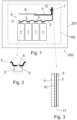
- Figure 1 is a schematic view of a battery and battery module
- Figure 2 is a schematic view of a detail of the battery and battery module shown in Figure 1
- Figure 3 is a schematic view of another detail of the battery and battery module shown in Figure 1 .
- the battery 200 is a drive battery of a fully or partly electricity-driven vehicle, such as a car. In one embodiment, the battery 200 is a battery of a stationary electricity source.
- the battery module 100 (shown by dashed lines in Figure 1 ) is arranged in the battery 200.
- the battery 200 may comprise many battery modules 100 and other modules arranged in a battery casing 201 that is arranged to protect components of the battery 200.
- the battery module 100 comprises plurality of battery cells 1.
- the battery cell has a terminal 2 made of aluminium or aluminium alloy.
- the terminal 2 is the electrical contact that is used to connect a load or charger to the corresponding battery cell.
- the battery cells 1 may constitute a cell stack (not shown), and the battery module 100 may comprise one or plurality of said cell stacks.
- the battery module 100 further comprises a busbar 3, typically plurality of busbars, that is made of aluminium or aluminium alloy.
- the busbar 3 is arranged for interconnecting terminals 2 in a same electrical polarity of said plurality of battery cells 1 in an electrically conductive way.
- the busbar 3 is attached and connected to the terminals 2 by a welded joint 6.
- the welded joint 6 is a laser welded joint, i.e. the made by a laser welding method.
- a process step where the surface of the busbar 3 to be welded is removed or processed, since the purposely passivated surface 5 does not cause harm to the welding process. Just normal cleaning of the surfaces is sufficient. This reduces significantly manufacturing costs of the battery module.
- the busbar 3 comprises a hole 9 that is positioned on the corresponding terminal 2.
- the hole 9 facilitates welding of the busbar to the terminal.
- busbar 3 is connected to an electrical conductor element 4 so that an electrical connection is provided between the plurality of battery cells connected to thereto and to said electrical conductor element 4.
- the electrical conductor element 4 is made of copper or copper alloy.
- the busbar 3 comprises a purposely passivated surface 5, such as shown in Figure 3 .
- the purposely passivated surface 5 is shown on one surface of the busbar only.
- all surfaces of the busbar 3 are covered by the purposely passivated surface 5.
- not all but those surfaces of the busbar 3 that are in contact with the electrical conductor element 4 comprises the purposely passivated surface 5.
- not all but those surfaces of the busbar 3 that are in contact with the electrical conductor element 4 and the terminal(s) 2 comprises the purposely passivated surface.
- the busbar 3 is attached to the electrical conductor element 4 by at least one mechanical fastening device 7 so that the surface of the busbar having the purposely passivated surface 5 is pressed or forced against the electrical conductor element 4.
- the busbar 3 and the electrical conductor element 4 are show as having a gap 11 therebetween in Figure 3 in order to clarify the distinction of said two components. But as disclosed above, in the battery module (as well as in the battery) the busbar 3 and the electrical conductor element 4 are in contact with each other, typically pressed or forced against each other.
- the mechanical fastening device 7 is a threaded fastening device, such as a screw or a bolt.
- the counterpart thread of the screw or the bolt may be manufactured to the busbar 3 and/or the electrical conductor element 4, or there may be a separate component therefor, such as a nut, a threaded sleeve or a screw bushing 12.
- the mechanical fastening device 7 is a rivet.
- the mechanical fastening device 7 provides a certain pressing force between the surfaces of the busbar 3 and the electrical conductor element 4 contacting each other.
- the busbar comprises the purposely passivated surface 5.
- the purposely passivated surface 5 comprises a conversion coating.
- the conversion coating is a type of coating used on metals in which the surface that is covered is turned into a coating with electrochemical or chemical processes.
- the conversion coating comprises zirconium Zr, fluorine F, and chromium Cr.
- the conversion coating comprises zirconium Zr, titanium Ti, and chromium Cr.
- the conversion coating is made of compound known as Candor E-CLPS ® .
- the conversion coating is manufactured by process known as Iridite NCP ® .
- the conversion coating is made of compound known as Surtec 650°.
- the thickness of the passivated surface 5 is in range of 0.5 - 1 ⁇ m.
- the purposely passivated surface 5 is manufactured by:
- the electrical conductor element 4 made of copper or copper alloy has a conductor surface 10, and the busbar 3 is attached to said conductor surface.
- the conductor surface 10 comprises a nickel-tin (Ni-Sn) coating or plating.
- the thickness of said Ni-Sn coating is in range of 0.5 - 2 ⁇ m.
- the conductor surface 10 comprises an Organic Solderability Preservative (OSP) coating.
- OSP Organic Solderability Preservative
- This coating may necessitate a stable, constant and sufficient compressive pressure between the electrical conductor element 4 and the busbar 3. This pressure may be secured by mechanical fastening devices 7, for instance.
- the conductor surface 10 comprises palladium (Pd) coating.
- the purposely passivated surface 5 comprises zirconium Zr, fluorine F and chromium Cr, and the conductor surface 10 of the electrical conductor element 4 has an OSP coating, and said surfaces 5, 10 are attached to each other.
- the electrical conductor element 4 electrically connects the busbar 3 to a circuitry 8.
- the circuitry 8 is a circuit board.
- the circuit board is a printed circuit board.
- the connection may be a direct one (such as shown in Figure 1 ), i.e. the electrical conductor element 4 is connected directly to the circuitry 8 without any intermediary components.
Landscapes
- Chemical & Material Sciences (AREA)
- Chemical Kinetics & Catalysis (AREA)
- Electrochemistry (AREA)
- General Chemical & Material Sciences (AREA)
- Inorganic Chemistry (AREA)
- Engineering & Computer Science (AREA)
- Microelectronics & Electronic Packaging (AREA)
- Manufacturing & Machinery (AREA)
- Connection Of Batteries Or Terminals (AREA)
Abstract
Description
- The invention relates to a battery module.
- The invention further relates to a battery.
- In batteries, such as in automotive batteries, battery cells have normally aluminium terminals that are laser welded to aluminium busbars connecting the cells to electrical circuit of the battery. The electrical circuit is mainly made of copper, and therefore the two conductive materials (aluminium and copper) must have a connection somewhere in the battery. Aluminum/copper connection is prone to electrochemical corrosion and resistance growth, which in time provides heat and potentially ages the battery cells prematurely. It is known to solve this problem by coating the aluminum and copper with the same coating, e.g. nickel and tin. A problem in this solution is that the busbar connected to battery cell terminals by laser welding may though not have said coating present when the welding takes place, since the Ni-Sn coating will gasify in the heat of the welding, which causes porosity in the welding and ruins the electrical connection therein. Therefore, said coating has to be removed prior to the welding. This causes lot of costs.
- Viewed from a first aspect, there can be provided a battery module comprising plurality of battery cells, the battery cell comprising a terminal made of aluminium or aluminium alloy, a busbar made of aluminium or aluminium alloy, the busbar being arranged for interconnecting terminals in a same electrical polarity of said plurality of battery cells in an electrically conductive way, the busbar further arranged for connecting the plurality of battery cells to an electrical conductor element made of copper or copper alloy, wherein the busbar comprises a purposely passivated surface.
- Thereby a battery module that can be assembled without expensive steps of removing or processing the busbar surface prior to its attachment to the terminals may be achieved.
- Viewed from a further aspect, there can be provided a battery, comprising the battery module as defined above.
- Thereby a battery that can be assembled without expensive steps of removing or processing the busbar surface prior to its attachment to the terminals may be achieved.
- The battery module and the battery are characterised by what is stated in the independent claims. Some other embodiments are characterised by what is stated in the other claims. Inventive embodiments are also disclosed in the specification and drawings of this patent application. The inventive content of the patent application may also be defined in other ways than defined in the following claims. The inventive content may also be formed of several separate inventions, especially if the invention is examined in the light of expressed or implicit sub-tasks or in view of obtained benefits or benefit groups. Some of the definitions contained in the following claims may then be unnecessary in view of the separate inventive ideas. Features of the different embodiments of the invention may, within the scope of the basic inventive idea, be applied to other embodiments.
- Various embodiments of the first aspect may comprise at least one feature from the following paragraphs:
In one embodiment, the purposely passivated surface of the busbar comprises a conversion coating. - An advantage is that the coating not only provides electrically conductive but also a corrosion resistant coating.
- In one embodiment, the conversion coating comprises zirconium Zr, fluorine F, and chromium Cr.
- An advantage is that a high surface conductivity of the busbar may be achieved. Further, said high surface conductivity is long lasting and stands well variations in ambient conditions. Still further, said conversion coating improves the quality of welding, especially laser welding, where the busbar is welded to the terminal, since oxides and water on the surfaces are substantially avoided. Thus, an excellent conductivity between the busbar and the terminal may be achieved.
- In one embodiment, the conversion coating comprises zirconium Zr, titanium Ti, and chromium Cr.
- An advantage is that a high surface conductivity of the busbar may be achieved. Additionally, said high surface conductivity is long lasting and stands well variations in ambient conditions. Still further, said conversion coating improves the quality of welding, especially laser welding, where the busbar is welded to the terminal, since oxides and water on the surfaces are substantially avoided. Thus, an excellent conductivity between the busbar and the terminal may be achieved.
- In one embodiment, the thickness of the passivated surface is in range of 0.5 - 1 µm.
- An advantage is that said thickness is sufficient to prevent or at least substantially delay corrosion of the surface while being as thin as possible on order to ensure good electrical conductivity between the connected surfaces.
- In one embodiment, the battery module comprises a welded joint attaching the terminal to the busbar, preferably a laser welded joint.
- An advantage is that a precise electrically conductive joint may be achieved.
- In one embodiment, the electrical conductor element comprises a conductor surface having a Ni-Sn coating, and the busbar is attached to said surface.
- An advantage is that tin provides good corrosion resistance and as a plastic material adapts to surface contour of the busbar, thereby a hermetic junction may be achieved. Nickel creates a diffusion-preventing barrier that prevents dissolving tin and copper to each other and thus may maintain good conductivity between the busbar and the electrical conductor element.
- In one embodiment, the electrical conductor element comprises a conductor surface having an OSP (Organic Solderability Preservative) coating, and the busbar is attached to said surface.
- An advantage is that a very thin coating where the thickness is in order of molecular dimensions for ensuring good electrical conductivity between the connected surfaces may be achieved.
- In one embodiment, the electrical conductor element comprises a conductor surface having a palladium (Pd) coating, and the busbar is attached to said surface.
- An advantage is that it is possible to manufacture very thin coating, since palladium can be provided highly impurity-free grades, and thus good electrical conductivity between the connected surfaces may be achieved. Further, palladium does not dissolve with substances and compounds typically present in batteries.
- In one embodiment, the busbar is attached to the electrical conductor element by a mechanical fastening device, such as a threaded fastening device or rivet.
- An advantage is that a reliable and simple attachment of the busbar and the electrical conductor element may be achieved.
- In one embodiment, it provided a sufficient pressing force between the contacting surfaces of the busbar and the electrical conductor element.
- An advantage is that an optimal electrically conductive contact between the busbar is attached to the electrical conductor element may be achieved.
- In one embodiment, the purposely passivated surface comprises zirconium Zr, fluorine F and chromium Cr, the conductor surface of the electrical conductor element has an OSP coating, and said surfaces are attached to each other.
- An advantage is that an optimal combination of electrically conductive surfaces between the busbar and the electrical conductor may be achieved.
- Some embodiments illustrating the present disclosure are described in more detail in the attached drawings, in which
-
Figure 1 is a schematic view of a battery and battery module, -
Figure 2 is a schematic view of a detail of the battery and battery module shown inFigure 1 , and -
Figure 3 is a schematic view of another detail of the battery and battery module shown inFigure 1 . - In the figures, some embodiments are shown simplified for the sake of clarity. Similar parts are marked with the same reference numbers in the figures.
-
Figure 1 is a schematic view of a battery and battery module,Figure 2 is a schematic view of a detail of the battery and battery module shown inFigure 1, and Figure 3 is a schematic view of another detail of the battery and battery module shown inFigure 1 . - In one embodiment, the
battery 200 is a drive battery of a fully or partly electricity-driven vehicle, such as a car. In one embodiment, thebattery 200 is a battery of a stationary electricity source. - The battery module 100 (shown by dashed lines in
Figure 1 ) is arranged in thebattery 200. Thebattery 200 may comprisemany battery modules 100 and other modules arranged in abattery casing 201 that is arranged to protect components of thebattery 200. - The
battery module 100 comprises plurality ofbattery cells 1. The battery cell has aterminal 2 made of aluminium or aluminium alloy. Theterminal 2 is the electrical contact that is used to connect a load or charger to the corresponding battery cell. - The
battery cells 1 may constitute a cell stack (not shown), and thebattery module 100 may comprise one or plurality of said cell stacks. - The
battery module 100 further comprises abusbar 3, typically plurality of busbars, that is made of aluminium or aluminium alloy. Thebusbar 3 is arranged for interconnectingterminals 2 in a same electrical polarity of said plurality ofbattery cells 1 in an electrically conductive way. - In one embodiment, the
busbar 3 is attached and connected to theterminals 2 by a welded joint 6. In one embodiment, the welded joint 6 is a laser welded joint, i.e. the made by a laser welding method. Prior to welding, there is no need for a process step where the surface of thebusbar 3 to be welded is removed or processed, since the purposely passivated surface 5 does not cause harm to the welding process. Just normal cleaning of the surfaces is sufficient. This reduces significantly manufacturing costs of the battery module. - In one embodiment, such as shown in
Figure 2 , thebusbar 3 comprises ahole 9 that is positioned on thecorresponding terminal 2. Thehole 9 facilitates welding of the busbar to the terminal. However, in some embodiments, there is not such a hole present. - Additionally, the
busbar 3 is connected to anelectrical conductor element 4 so that an electrical connection is provided between the plurality of battery cells connected to thereto and to saidelectrical conductor element 4. Theelectrical conductor element 4 is made of copper or copper alloy. - The
busbar 3 comprises a purposely passivated surface 5, such as shown inFigure 3 . InFigure 3 the purposely passivated surface 5 is shown on one surface of the busbar only. In another embodiment, all surfaces of thebusbar 3 are covered by the purposely passivated surface 5. In still another embodiment, not all but those surfaces of thebusbar 3 that are in contact with theelectrical conductor element 4 comprises the purposely passivated surface 5. In still another embodiment, not all but those surfaces of thebusbar 3 that are in contact with theelectrical conductor element 4 and the terminal(s) 2 comprises the purposely passivated surface. - In one embodiment, such as shown in
Figure 1 , thebusbar 3 is attached to theelectrical conductor element 4 by at least onemechanical fastening device 7 so that the surface of the busbar having the purposely passivated surface 5 is pressed or forced against theelectrical conductor element 4. It is to be noted that thebusbar 3 and theelectrical conductor element 4 are show as having agap 11 therebetween inFigure 3 in order to clarify the distinction of said two components. But as disclosed above, in the battery module (as well as in the battery) thebusbar 3 and theelectrical conductor element 4 are in contact with each other, typically pressed or forced against each other. - In one embodiment, the
mechanical fastening device 7 is a threaded fastening device, such as a screw or a bolt. The counterpart thread of the screw or the bolt may be manufactured to thebusbar 3 and/or theelectrical conductor element 4, or there may be a separate component therefor, such as a nut, a threaded sleeve or ascrew bushing 12. - In one embodiment, the
mechanical fastening device 7 is a rivet. - The
mechanical fastening device 7 provides a certain pressing force between the surfaces of thebusbar 3 and theelectrical conductor element 4 contacting each other. - As already described, the busbar comprises the purposely passivated surface 5. In one embodiment, the purposely passivated surface 5 comprises a conversion coating. The conversion coating is a type of coating used on metals in which the surface that is covered is turned into a coating with electrochemical or chemical processes.
- In one embodiment, the conversion coating comprises zirconium Zr, fluorine F, and chromium Cr.
- In one embodiment, the conversion coating comprises zirconium Zr, titanium Ti, and chromium Cr.
- In one embodiment, the conversion coating is made of compound known as Candor E-CLPS®.
- In one embodiment, the conversion coating is manufactured by process known as Iridite NCP®.
- In one embodiment, the conversion coating is made of compound known as Surtec 650°.
- In one embodiment, the thickness of the passivated surface 5 is in range of 0.5 - 1 µm.
- In one embodiment, the purposely passivated surface 5 is manufactured by:
- a) washing the surface to be passivated for removing greases, carbon-containing substances etc.,
- b) treating the washed surface with alkaline solution that etches and smooths aluminium surface,
- c) pickling with acid in order to homogenize the surfaces, and
- d) dipping the surface in solution that creates the passivated surface.
- In one embodiment, the
electrical conductor element 4 made of copper or copper alloy has aconductor surface 10, and thebusbar 3 is attached to said conductor surface. In one embodiment, theconductor surface 10 comprises a nickel-tin (Ni-Sn) coating or plating. In one embodiment, the thickness of said Ni-Sn coating is in range of 0.5 - 2 µm. - In one embodiment, the
conductor surface 10 comprises an Organic Solderability Preservative (OSP) coating. This coating may necessitate a stable, constant and sufficient compressive pressure between theelectrical conductor element 4 and thebusbar 3. This pressure may be secured bymechanical fastening devices 7, for instance. - In one embodiment, the
conductor surface 10 comprises palladium (Pd) coating. - In one embodiment, the purposely passivated surface 5 comprises zirconium Zr, fluorine F and chromium Cr, and the
conductor surface 10 of theelectrical conductor element 4 has an OSP coating, and saidsurfaces 5, 10 are attached to each other. - In one embodiment, the
electrical conductor element 4 electrically connects thebusbar 3 to acircuitry 8. In one embodiment, thecircuitry 8 is a circuit board. In one embodiment, the circuit board is a printed circuit board. The connection may be a direct one (such as shown inFigure 1 ), i.e. theelectrical conductor element 4 is connected directly to thecircuitry 8 without any intermediary components. In another embodiment, there is at least one transmission component or conductor element arranged for conducting electricity between thebusbar 3 and thecircuitry 8. - The invention is not limited solely to the embodiments described above, but instead many variations are possible within the scope of the inventive concept defined by the claims below. Within the scope of the inventive concept the attributes of different embodiments and applications can be used in conjunction with or replace the attributes of another embodiment or application.
- The drawings and the related description are only intended to illustrate the idea of the invention. The invention may vary in detail within the scope of the inventive idea defined in the following claims.
-
- 1
- battery cell
- 2
- terminal
- 3
- busbar
- 4
- electrical conductor element
- 5
- purposely passivated surface
- 6
- welded joint
- 7
- mechanical fastening device
- 8
- circuitry
- 9
- hole
- 10
- conductor surface
- 11
- gap
- 12
- threaded sleeve
- 100
- battery module
- 200
- battery
- 201
- battery casing
Claims (14)
- A battery module (100) comprising- plurality of battery cells (1),- the battery cell comprising a terminal (2) made of aluminium or aluminium alloy,- a busbar (3) made of aluminium or aluminium alloy,the busbar being arranged for interconnecting terminals (2) in a same electrical polarity of said plurality of battery cells (1) in an electrically conductive way,- the busbar (3) further arranged for connecting the plurality of battery cells to an electrical conductor element (4) made of copper or copper alloy, wherein- the busbar (3) comprises a purposely passivated surface (5) .
- The battery module as claimed in claim 1, wherein- the purposely passivated surface (5) of the busbar comprises a conversion coating.
- The battery module as claimed in claim 2, wherein- the conversion coating comprises zirconium Zr, fluorine F, and chromium Cr.
- The battery module as claimed in claim 2, wherein- the conversion coating comprises zirconium Zr, titanium Ti, and chromium Cr.
- The battery module as claimed in any of the preceding claims, wherein- the thickness of the passivated surface (5) is in range of 0.5 - 1 pm.
- The battery module as claimed in any of the preceding claims, comprising- a welded joint (6) attaching the terminal (2) to the busbar (3).
- The battery module as claimed in claim 6, wherein- the welded joint (6) is a laser welded joint.
- The battery module as claimed in any of the preceding claims, wherein- the electrical conductor element (4) comprises a conductor surface (10) having a Ni-Sn coating or OSP (Organic Solderability Preservative) coating or palladium (Pd) coating, and- the busbar (3) is attached to said surface.
- The battery module as claimed in any of the preceding claims, wherein- the busbar (3) is attached to the electrical conductor element (4) by a mechanical fastening device (7), such as a threaded fastening device or rivet.
- The battery module as claimed in claim 9, comprising- providing a pressing force between the contacting surfaces of the busbar (3) and the electrical conductor element (4) .
- The battery module as claimed in any of the preceding claims, wherein- the purposely passivated surface comprising zirconium Zr, fluorine and chromium Cr,- the conductor surface (10) of the electrical conductor element (4) having an OSP coating, and- said surfaces being attached to each other.
- A battery (200), comprising- at least one battery module (100) as claimed in any of the preceding claims.
- The battery as claimed in claim 12, being- a drive battery of a fully or partly electricity-driven vehicle.
- The battery as claimed in claim 12, being a battery of a stationary electricity source.
Priority Applications (2)
| Application Number | Priority Date | Filing Date | Title |
|---|---|---|---|
| EP22214053.5A EP4386931B1 (en) | 2022-12-16 | 2022-12-16 | Battery module and battery |
| US18/539,607 US20240204368A1 (en) | 2022-12-16 | 2023-12-14 | Battery module and battery |
Applications Claiming Priority (1)
| Application Number | Priority Date | Filing Date | Title |
|---|---|---|---|
| EP22214053.5A EP4386931B1 (en) | 2022-12-16 | 2022-12-16 | Battery module and battery |
Publications (2)
| Publication Number | Publication Date |
|---|---|
| EP4386931A1 true EP4386931A1 (en) | 2024-06-19 |
| EP4386931B1 EP4386931B1 (en) | 2025-04-23 |
Family
ID=84537429
Family Applications (1)
| Application Number | Title | Priority Date | Filing Date |
|---|---|---|---|
| EP22214053.5A Active EP4386931B1 (en) | 2022-12-16 | 2022-12-16 | Battery module and battery |
Country Status (2)
| Country | Link |
|---|---|
| US (1) | US20240204368A1 (en) |
| EP (1) | EP4386931B1 (en) |
Citations (3)
| Publication number | Priority date | Publication date | Assignee | Title |
|---|---|---|---|---|
| US20120000964A1 (en) * | 2010-07-01 | 2012-01-05 | Gm Global Technology Operations, Inc. | Battery tab joints and methods of making |
| WO2016040040A1 (en) * | 2014-09-10 | 2016-03-17 | Cellink Corporation | Interconnect for battery packs |
| WO2017062886A1 (en) * | 2015-10-08 | 2017-04-13 | Cellink Corporation | Battery interconnects |
-
2022
- 2022-12-16 EP EP22214053.5A patent/EP4386931B1/en active Active
-
2023
- 2023-12-14 US US18/539,607 patent/US20240204368A1/en active Pending
Patent Citations (3)
| Publication number | Priority date | Publication date | Assignee | Title |
|---|---|---|---|---|
| US20120000964A1 (en) * | 2010-07-01 | 2012-01-05 | Gm Global Technology Operations, Inc. | Battery tab joints and methods of making |
| WO2016040040A1 (en) * | 2014-09-10 | 2016-03-17 | Cellink Corporation | Interconnect for battery packs |
| WO2017062886A1 (en) * | 2015-10-08 | 2017-04-13 | Cellink Corporation | Battery interconnects |
Also Published As
| Publication number | Publication date |
|---|---|
| US20240204368A1 (en) | 2024-06-20 |
| EP4386931B1 (en) | 2025-04-23 |
Similar Documents
| Publication | Publication Date | Title |
|---|---|---|
| CN113708172A (en) | Electric energy transmission changeover mechanism, charging socket and motor vehicle | |
| US9455502B2 (en) | Press-in contact | |
| CN216251492U (en) | A power transmission and transfer mechanism, charging socket and motor vehicle | |
| WO2024222715A1 (en) | Multi-coating terminal and conductive structure | |
| CN202564554U (en) | Connecting structure for device and connection terminal | |
| EP4386931A1 (en) | Battery module and battery | |
| US20090111294A1 (en) | Bus bar to printed circuit board interface for electric and hybrid electric vehicles | |
| US20070155149A1 (en) | Methods and structures for electrically coupling a conductor and a conductive element comprising a dissimilar material | |
| EP4327411B1 (en) | Connection assembly, in particular for use in electric vehicles or hybrid vehicles | |
| KR101400733B1 (en) | Surface structure of conducting element, washer and crimp terminal having the surface structure | |
| CN217009626U (en) | Connector and vehicle | |
| US20240120151A1 (en) | System including a bent capacitor bus bar | |
| US6360437B1 (en) | Electrical contact having surface coating layer with irregular surface due to hard particles dispersed in the surface coating layer | |
| JP5063672B2 (en) | Wiring board and manufacturing method thereof | |
| CN209913075U (en) | Prevent dust PCB board binding post | |
| CN222940212U (en) | Connecting assembly and current conducting piece for new energy automobile | |
| CN209982824U (en) | Interconnecting and switching structure between PCBs | |
| CN2478259Y (en) | Power line connecting tool | |
| US20250323429A1 (en) | Connection arrangement, in particular for use in electric vehicles or hybrid vehicles | |
| CN221862121U (en) | Composite busbar without rivet riveting | |
| CN219163731U (en) | Connector | |
| CN221747510U (en) | Busbar assembly and power conversion device | |
| CN220556644U (en) | Bus bar and power electronic unit including the same | |
| Lee et al. | Low power commercial automotive and appliance connections | |
| CN213212428U (en) | An electrical connector and connector |
Legal Events
| Date | Code | Title | Description |
|---|---|---|---|
| PUAI | Public reference made under article 153(3) epc to a published international application that has entered the european phase |
Free format text: ORIGINAL CODE: 0009012 |
|
| STAA | Information on the status of an ep patent application or granted ep patent |
Free format text: STATUS: THE APPLICATION HAS BEEN PUBLISHED |
|
| AK | Designated contracting states |
Kind code of ref document: A1 Designated state(s): AL AT BE BG CH CY CZ DE DK EE ES FI FR GB GR HR HU IE IS IT LI LT LU LV MC ME MK MT NL NO PL PT RO RS SE SI SK SM TR |
|
| STAA | Information on the status of an ep patent application or granted ep patent |
Free format text: STATUS: REQUEST FOR EXAMINATION WAS MADE |
|
| 17P | Request for examination filed |
Effective date: 20241016 |
|
| RBV | Designated contracting states (corrected) |
Designated state(s): AL AT BE BG CH CY CZ DE DK EE ES FI FR GB GR HR HU IE IS IT LI LT LU LV MC ME MK MT NL NO PL PT RO RS SE SI SK SM TR |
|
| GRAP | Despatch of communication of intention to grant a patent |
Free format text: ORIGINAL CODE: EPIDOSNIGR1 |
|
| STAA | Information on the status of an ep patent application or granted ep patent |
Free format text: STATUS: GRANT OF PATENT IS INTENDED |
|
| RIC1 | Information provided on ipc code assigned before grant |
Ipc: H01M 50/562 20210101ALI20241108BHEP Ipc: H01M 50/528 20210101ALI20241108BHEP Ipc: H01M 50/526 20210101ALI20241108BHEP Ipc: H01M 50/522 20210101ALI20241108BHEP Ipc: H01M 50/516 20210101ALI20241108BHEP Ipc: H01M 50/512 20210101ALI20241108BHEP Ipc: H01M 50/505 20210101ALI20241108BHEP Ipc: H01M 50/284 20210101ALI20241108BHEP Ipc: H01M 10/42 20060101AFI20241108BHEP |
|
| INTG | Intention to grant announced |
Effective date: 20241127 |
|
| GRAS | Grant fee paid |
Free format text: ORIGINAL CODE: EPIDOSNIGR3 |
|
| GRAA | (expected) grant |
Free format text: ORIGINAL CODE: 0009210 |
|
| STAA | Information on the status of an ep patent application or granted ep patent |
Free format text: STATUS: THE PATENT HAS BEEN GRANTED |
|
| AK | Designated contracting states |
Kind code of ref document: B1 Designated state(s): AL AT BE BG CH CY CZ DE DK EE ES FI FR GB GR HR HU IE IS IT LI LT LU LV MC ME MK MT NL NO PL PT RO RS SE SI SK SM TR |
|
| RAP1 | Party data changed (applicant data changed or rights of an application transferred) |
Owner name: IONCOR OY |
|
| REG | Reference to a national code |
Ref country code: GB Ref legal event code: FG4D |
|
| P01 | Opt-out of the competence of the unified patent court (upc) registered |
Free format text: CASE NUMBER: APP_14704/2025 Effective date: 20250326 |
|
| REG | Reference to a national code |
Ref country code: CH Ref legal event code: EP |
|
| REG | Reference to a national code |
Ref country code: DE Ref legal event code: R096 Ref document number: 602022013508 Country of ref document: DE |
|
| REG | Reference to a national code |
Ref country code: IE Ref legal event code: FG4D |
|
| REG | Reference to a national code |
Ref country code: NL Ref legal event code: MP Effective date: 20250423 |
|
| PG25 | Lapsed in a contracting state [announced via postgrant information from national office to epo] |
Ref country code: NL Free format text: LAPSE BECAUSE OF FAILURE TO SUBMIT A TRANSLATION OF THE DESCRIPTION OR TO PAY THE FEE WITHIN THE PRESCRIBED TIME-LIMIT Effective date: 20250423 |
|
| REG | Reference to a national code |
Ref country code: AT Ref legal event code: MK05 Ref document number: 1788714 Country of ref document: AT Kind code of ref document: T Effective date: 20250423 |
|
| PG25 | Lapsed in a contracting state [announced via postgrant information from national office to epo] |
Ref country code: FI Free format text: LAPSE BECAUSE OF FAILURE TO SUBMIT A TRANSLATION OF THE DESCRIPTION OR TO PAY THE FEE WITHIN THE PRESCRIBED TIME-LIMIT Effective date: 20250423 Ref country code: PT Free format text: LAPSE BECAUSE OF FAILURE TO SUBMIT A TRANSLATION OF THE DESCRIPTION OR TO PAY THE FEE WITHIN THE PRESCRIBED TIME-LIMIT Effective date: 20250825 Ref country code: ES Free format text: LAPSE BECAUSE OF FAILURE TO SUBMIT A TRANSLATION OF THE DESCRIPTION OR TO PAY THE FEE WITHIN THE PRESCRIBED TIME-LIMIT Effective date: 20250423 |
|
| REG | Reference to a national code |
Ref country code: LT Ref legal event code: MG9D |
|
| PG25 | Lapsed in a contracting state [announced via postgrant information from national office to epo] |
Ref country code: GR Free format text: LAPSE BECAUSE OF FAILURE TO SUBMIT A TRANSLATION OF THE DESCRIPTION OR TO PAY THE FEE WITHIN THE PRESCRIBED TIME-LIMIT Effective date: 20250724 Ref country code: NO Free format text: LAPSE BECAUSE OF FAILURE TO SUBMIT A TRANSLATION OF THE DESCRIPTION OR TO PAY THE FEE WITHIN THE PRESCRIBED TIME-LIMIT Effective date: 20250723 |
|
| PG25 | Lapsed in a contracting state [announced via postgrant information from national office to epo] |
Ref country code: PL Free format text: LAPSE BECAUSE OF FAILURE TO SUBMIT A TRANSLATION OF THE DESCRIPTION OR TO PAY THE FEE WITHIN THE PRESCRIBED TIME-LIMIT Effective date: 20250423 |
|
| PG25 | Lapsed in a contracting state [announced via postgrant information from national office to epo] |
Ref country code: BG Free format text: LAPSE BECAUSE OF FAILURE TO SUBMIT A TRANSLATION OF THE DESCRIPTION OR TO PAY THE FEE WITHIN THE PRESCRIBED TIME-LIMIT Effective date: 20250423 |
|
| PG25 | Lapsed in a contracting state [announced via postgrant information from national office to epo] |
Ref country code: HR Free format text: LAPSE BECAUSE OF FAILURE TO SUBMIT A TRANSLATION OF THE DESCRIPTION OR TO PAY THE FEE WITHIN THE PRESCRIBED TIME-LIMIT Effective date: 20250423 |
|
| PG25 | Lapsed in a contracting state [announced via postgrant information from national office to epo] |
Ref country code: AT Free format text: LAPSE BECAUSE OF FAILURE TO SUBMIT A TRANSLATION OF THE DESCRIPTION OR TO PAY THE FEE WITHIN THE PRESCRIBED TIME-LIMIT Effective date: 20250423 |
|
| PG25 | Lapsed in a contracting state [announced via postgrant information from national office to epo] |
Ref country code: RS Free format text: LAPSE BECAUSE OF FAILURE TO SUBMIT A TRANSLATION OF THE DESCRIPTION OR TO PAY THE FEE WITHIN THE PRESCRIBED TIME-LIMIT Effective date: 20250723 |
|
| PG25 | Lapsed in a contracting state [announced via postgrant information from national office to epo] |
Ref country code: IS Free format text: LAPSE BECAUSE OF FAILURE TO SUBMIT A TRANSLATION OF THE DESCRIPTION OR TO PAY THE FEE WITHIN THE PRESCRIBED TIME-LIMIT Effective date: 20250823 |
|
| PG25 | Lapsed in a contracting state [announced via postgrant information from national office to epo] |
Ref country code: LV Free format text: LAPSE BECAUSE OF FAILURE TO SUBMIT A TRANSLATION OF THE DESCRIPTION OR TO PAY THE FEE WITHIN THE PRESCRIBED TIME-LIMIT Effective date: 20250423 |
|
| PG25 | Lapsed in a contracting state [announced via postgrant information from national office to epo] |
Ref country code: DK Free format text: LAPSE BECAUSE OF FAILURE TO SUBMIT A TRANSLATION OF THE DESCRIPTION OR TO PAY THE FEE WITHIN THE PRESCRIBED TIME-LIMIT Effective date: 20250423 Ref country code: SM Free format text: LAPSE BECAUSE OF FAILURE TO SUBMIT A TRANSLATION OF THE DESCRIPTION OR TO PAY THE FEE WITHIN THE PRESCRIBED TIME-LIMIT Effective date: 20250423 |
|
| PGFP | Annual fee paid to national office [announced via postgrant information from national office to epo] |
Ref country code: FR Payment date: 20251211 Year of fee payment: 4 |
|
| PG25 | Lapsed in a contracting state [announced via postgrant information from national office to epo] |
Ref country code: CZ Free format text: LAPSE BECAUSE OF FAILURE TO SUBMIT A TRANSLATION OF THE DESCRIPTION OR TO PAY THE FEE WITHIN THE PRESCRIBED TIME-LIMIT Effective date: 20250423 |
|
| PG25 | Lapsed in a contracting state [announced via postgrant information from national office to epo] |
Ref country code: EE Free format text: LAPSE BECAUSE OF FAILURE TO SUBMIT A TRANSLATION OF THE DESCRIPTION OR TO PAY THE FEE WITHIN THE PRESCRIBED TIME-LIMIT Effective date: 20250423 |
|
| REG | Reference to a national code |
Ref country code: DE Ref legal event code: R097 Ref document number: 602022013508 Country of ref document: DE |
|
| PG25 | Lapsed in a contracting state [announced via postgrant information from national office to epo] |
Ref country code: SK Free format text: LAPSE BECAUSE OF FAILURE TO SUBMIT A TRANSLATION OF THE DESCRIPTION OR TO PAY THE FEE WITHIN THE PRESCRIBED TIME-LIMIT Effective date: 20250423 |
|
| PLBE | No opposition filed within time limit |
Free format text: ORIGINAL CODE: 0009261 |
|
| STAA | Information on the status of an ep patent application or granted ep patent |
Free format text: STATUS: NO OPPOSITION FILED WITHIN TIME LIMIT |
|
| REG | Reference to a national code |
Ref country code: CH Ref legal event code: L10 Free format text: ST27 STATUS EVENT CODE: U-0-0-L10-L00 (AS PROVIDED BY THE NATIONAL OFFICE) Effective date: 20260304 |
|
| PG25 | Lapsed in a contracting state [announced via postgrant information from national office to epo] |
Ref country code: RO Free format text: LAPSE BECAUSE OF FAILURE TO SUBMIT A TRANSLATION OF THE DESCRIPTION OR TO PAY THE FEE WITHIN THE PRESCRIBED TIME-LIMIT Effective date: 20250423 |
|
| 26N | No opposition filed |
Effective date: 20260126 |
|
| PGFP | Annual fee paid to national office [announced via postgrant information from national office to epo] |
Ref country code: DE Payment date: 20251222 Year of fee payment: 4 |
|
| PGFP | Annual fee paid to national office [announced via postgrant information from national office to epo] |
Ref country code: IT Payment date: 20251231 Year of fee payment: 4 |