EP4386799A1 - Disconnector or earthing switch - Google Patents
Disconnector or earthing switch Download PDFInfo
- Publication number
- EP4386799A1 EP4386799A1 EP22214242.4A EP22214242A EP4386799A1 EP 4386799 A1 EP4386799 A1 EP 4386799A1 EP 22214242 A EP22214242 A EP 22214242A EP 4386799 A1 EP4386799 A1 EP 4386799A1
- Authority
- EP
- European Patent Office
- Prior art keywords
- disconnector
- earthing switch
- worm wheel
- partially toothed
- worm
- Prior art date
- Legal status (The legal status is an assumption and is not a legal conclusion. Google has not performed a legal analysis and makes no representation as to the accuracy of the status listed.)
- Pending
Links
Images



Classifications
-
- H—ELECTRICITY
- H01—ELECTRIC ELEMENTS
- H01H—ELECTRIC SWITCHES; RELAYS; SELECTORS; EMERGENCY PROTECTIVE DEVICES
- H01H31/00—Air-break switches for high tension without arc-extinguishing or arc-preventing means
- H01H31/02—Details
-
- H—ELECTRICITY
- H01—ELECTRIC ELEMENTS
- H01H—ELECTRIC SWITCHES; RELAYS; SELECTORS; EMERGENCY PROTECTIVE DEVICES
- H01H3/00—Mechanisms for operating contacts
- H01H3/32—Driving mechanisms, i.e. for transmitting driving force to the contacts
- H01H3/40—Driving mechanisms, i.e. for transmitting driving force to the contacts using friction, toothed, or screw-and-nut gearing
-
- H—ELECTRICITY
- H01—ELECTRIC ELEMENTS
- H01H—ELECTRIC SWITCHES; RELAYS; SELECTORS; EMERGENCY PROTECTIVE DEVICES
- H01H31/00—Air-break switches for high tension without arc-extinguishing or arc-preventing means
- H01H31/003—Earthing switches
-
- H—ELECTRICITY
- H01—ELECTRIC ELEMENTS
- H01H—ELECTRIC SWITCHES; RELAYS; SELECTORS; EMERGENCY PROTECTIVE DEVICES
- H01H31/00—Air-break switches for high tension without arc-extinguishing or arc-preventing means
- H01H31/26—Air-break switches for high tension without arc-extinguishing or arc-preventing means with movable contact that remains electrically connected to one line in open position of switch
- H01H31/32—Air-break switches for high tension without arc-extinguishing or arc-preventing means with movable contact that remains electrically connected to one line in open position of switch with rectilinearly-movable contact
Definitions
- the invention relates to a disconnector or earthing switch for connecting three conductors of different phases to a respective switching tube, comprising a rotatable drive shaft comprising a worm and configured for operating the earthing switch and the three respective switching tubes, which are arranged axially together movable between a connected position configured for connecting the three conductors and a disconnected position configured for not connecting the three conductors.
- a disconnector or earthing switch also known a grounding switch, is a protective device included in switchgear components like circuit breakers and isolators. When circuit breakers are removed and racked out, earthing switches automatically ground a part of a bus bar adjacent to the circuit breakers. For isolators, the earthing switches make contact with the bus bar when the isolator isolates the circuits, discharging any charges that may have gathered there.
- an earthing switch in switchgear is used to ground a remaining change in a power line after the power line has been removed from its source. A residual charge often remains in a circuit after it has been severed or opened by the circuit breaker and isolator. An earthing switch is usually provided to discharge the charge.
- Disconnector or earthing switches often have a snap action closing mechanism for protecting technicians and staff when there is an abnormal current.
- disconnector or earthing switches are designed to withstand short circuits.
- the disconnector or earthing switch in a substation has an ability to create short circuits in order to safeguard other electrical devices from damage.
- the disconnector or earthing switch is often used with several high-voltage switchgear and also serves as a protective device in an overhaul of high-voltage electrical equipment.
- Such disconnector or earthing switch can be motorized or manually operated.
- end switches When a drive of the disconnector or earthing switch is operated by motor, end switches must be present for delimit traverse of an operating mechanism actuated by the motor. During hand operation defined end positions need to be defined.
- prior art solutions unfortunately do not provide sufficiently secure and easy operation mechanism for actuating such disconnector or earthing switch.
- an in particular high voltage disconnector or earthing switch for connecting three conductors of different phases to a respective switching tube, comprising
- the proposed solution thus constitutes a kind of position-controlled freewheel, acting in directions of rotation of the partially toothed worm wheel.
- the voltage disconnector or earthing switch allows transmitting high torques and at a same time providing said freewheel function in a very small installation space.
- the function of the proposed freewheel is based on the principle of geometrically controlled decoupling of two gearing partners, namely the partially toothed worm wheel and the rotatable drive shaft.
- torque and rotary motion are only transmitted for a defined range of motion between the rotatable drive shaft and the partially toothed worm wheel.
- the proposed freewheel composed of the rotatable drive shaft and the partially toothed worm wheel can be used as a safety device to safeguard a motor-driven mechanism in end positions in addition to electrical shutdown devices, for example limit switches, and for decoupling input and output sides mechanically precisely, without an influence of a coasting behaviour of the motor.
- the proposed freewheel can be used to prevent excessive operation. Therefore, the operator can never move the rotatable drive shaft further than the freewheel allows. The operator receives audible feedback that he has reached the freewheel from the sound made when the tooth flanks alternately meet.
- high voltage means preferably a voltage ranging from 36 to 1,100 kV.
- a high voltage preferably relates to nominal voltages in the range from above 72 kV to 550 kV, like 145 kV, 245 kV or 420 kV, or even more.
- Nominal currents of the disconnector or earthing switch can be in the range from 1 kA to 5 kA, even higher such as 80 kA for one second.
- the conductors can be part of a grid for distribution of said high voltage.
- the rotatable drive shaft is preferably hold by two bearings, in between which the worm is provided on the drive shaft.
- the bearings can be attached to a housing of the disconnector or earthing switch.
- One end of the rotatable drive shaft is preferably configured for connecting to the motor or a manual handle for rotating the drive shaft so as the operating the disconnector or earthing switch.
- the three switching tubes can be provided as rods and/or can extend parallel to the rotatable drive shaft.
- the partially toothed worm wheel is preferably arranged on an output shaft, which axis extends orthogonal to the drive shaft. Said output shaft can be attached via another bearing to the housing.
- Partially toothed means preferably that at least a portion of a circumference of the worm wheel is provided without tooths, while the remaining portion is provided with tooths corresponding to the worm. Saaid portion without tooths is not in engagement with the worm.
- the worm can be provided as an external thread.
- the re-engagement device is preferably triggered by the connected position and the disconnected position and/or when the connected position and the disconnected position is being reached to again engaging the partially toothed worm wheel with the worm.
- tooths of the partially toothed worm wheel extends about ⁇ 180°, ⁇ 160°, ⁇ 140°, ⁇ 120° or ⁇ 100°.
- preferably > 180°, > 200°, > 220°, > 240° or > 260° of the partially toothed worm wheel are provided free of tooths.
- the partially toothed worm wheel preferably comprises a disc-like form, whereby the tooths are arranged at a radial circumference.
- the tooths and the worm may comprise any suitable form allowing a respective mesh with each other.
- the partially toothed worm wheel is provided as a pitch circle shaped disc having opposite end surfaces for engaging with the re-engagement device.
- the pitch circle shaped disc may comprise a form of a piece of pie, with the tooths arranged along the circumference i.e. at the pieces. A remaining part i.e. where not pieces of pie are present can be hollow.
- the end surfaces preferably extend axial and radial to the output shaft as axis of the partially toothed worm wheel.
- the worm wheel is preferably rigidly connected to the output shaft. The end surfaces preferably engage with the re-engagement device in the connected position and the disconnected position for respectively triggering the re-engagement device for again engaging the partially toothed worm wheel with the worm.
- the re-engagement device is configured chargeable by the partially toothed worm wheel reaching the connected position respectively the disconnected position for again engaging the partially toothed worm wheel with the worm.
- Charging the re-engagement device means for example that a force is created at the re-engagement device which then allows for again engaging the partially toothed worm wheel with the worm.
- the re-engagement device is provided as torsion spring and/or as compression spring configured for applying a spring force onto the partially toothed worm wheel and/or as repulsive magnet pair configured for applying a repulsive magnetic force onto the partially toothed worm wheel.
- the torsion spring can be housed in a torsion spring housing and may have two torsion spring legs, whereby each leg is for engaging the worm wheel with the worm in the connected position and in the disconnected position.
- the disconnector or earthing switch comprises a contact support holding the three switching tubes distant to each other and/or a guidance configured for guiding the axial movement of the respective switching tube.
- the contact support preferably extends parallel to the output shaft and/or orthogonal to the switching tubes and/or the rotatable drive shaft.
- the contact support may comprise a triangular-like form having three edges with one switching tube arranged at each one edge.
- the guidance can be provided as sliding contact for guiding and/or providing electrical connection to the respective switching tube.
- the disconnector or earthing switch comprises a fork and bolt connection configured for translating a rotation of the partially toothed worm wheel into the axial movement of the three switching tubes.
- the fork is rigidly connected to the output shaft, while the fork can be rigidly connected to another switching tube and/or a rod connected in parallel and stationary to the three switching tubes.
- the switching tubes are connected by two opposite arranged bolts and two opposite arranged forks to the partially toothed worm wheel.
- each switching tube comprises a contact pin configured for connecting a contact tulip of the respective conductor.
- the contact pins are preferably arranged in regular distances to each other.
- the three switching tubes are connected to ground. Such wise the three switching tubes are connected together and/or may comprise a common connector. Alternatively, the three switching tubes can be connected to a respective another conductor.
- the disconnector or earthing switch is provided as fast acting earthing switch, make proof earthing switch or disconnector earthing switch.
- the proposed solution thereby allows for installing the respective fast acting earthing switch, make proof earthing switch or disconnector earthing switch are very small installation spaces.
- the object is further solved by a use of a partially toothed worm wheel for connecting three conductors of different phases to a respective switching tube, comprising
- Fig. 1 shows a disconnector or earthing switch 1 for connecting three conductors 2 of different phases to a respective switching tube 3 in a perspective view according to a preferred implementation.
- the three conductors 2 are part of grid each thus carry a high voltage in a range of 36 to 800 kV.
- the disconnector or earthing switch 1 comprises a rotatable drive shaft 4, the three respective switching tubes 3, a partially toothed worm wheel 5 and a re-engagement device 6.
- the rotatable drive shaft 4 is equipped with a worm 7 firmly connected to the rotatable drive shaft 4.
- the rotatable drive shaft 4 is being hold by two bearings 8 at a housing, not shown, of the disconnector or earthing switch 1.
- the worm 7 is arranged between the two bearings 8.
- One end 9 of the rotatable drive shaft 4 is configured for being operated by a motor or a handle, not shown, for operating the disconnector or earthing switch 1.
- the three switching tubes 3 extend parallel to the rotatable drive shaft 4 and are being hold by a contact support 10 having a triangular form with one switching tube 3 arranged at one edge each.
- the three switching tubes 3 are such wise motion coupled by the contact support 10 and being hold by guidances 11 provided as sliding contacts at the housing. All three guidances 11 are connected to ground as shown in the figure for the earthing switch 1. On case of a disconnector said three guidances 11 can be connected to other conductors.
- the three guidances 11 allow that the three switching tubes 3 can be axially moved together between a connected position, in which each one switching tube 3 electrically connects each one conductor 2, not shown in Fig. 1 , and a disconnected position, in which each one switching tube 3 is electrically disconnected from each one conductor 2, shown in Fig. 1 .
- Each tip of the three switching tubes 3 therefore comprises a contact pin 12 and each tip of the three conductors 2 comprises a corresponding contact tulip 13.
- the partially toothed worm wheel 5 comprises an output shaft 15, which is hold by the housing via anther bearing 8. Such wise the output shaft 15 extends orthogonal to the rotatable drive shaft 4.
- a fork and bolt connection 16 which connects to the output shaft 15 to a rod 17 connected in parallel and stationary to the three switching tubes 3 to the contact support 10.
- Two opposite arranged bolts extend from the rod 17, which are encompassed by two respective opposite arranged forks connected to the output shaft 15. Such way a rotation of the rotatable drive shaft 4 is translated into an axial movement of the three switching tubes 3 for moving the three switching tubes between the connected position and the disconnected position.
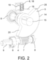
- FIG. 2 to 6 showing the rotatable drive shaft 4 and the partially toothed worm wheel 5 of the disconnector or earthing switch 1 according to Fig. 1 according to the preferred implementation
- Figs. 2 and 3 show the rotatable drive shaft 4 and the partially toothed worm wheel 5 fully engaged i.e. tooths of the worm 7 engage with tooths 14 of the partially toothed worm wheel 5.
- Said tooths 14 extend around 120° of a circumference of the partially toothed worm wheel 5.
- the partially toothed worm wheel 5 is provided as a pitch circle shaped disc i.e. a piece of cake extending around 120°.
- Said pitch circle shaped disc comprises at its ends two opposite arranged end surfaces 20, which extend axial and radial in respect to the output shaft 15. In Figs. 2 and 3 said end surfaces 20 do not engage with the re-engagement device 6
- Fig. 4 shows the rotatable drive shaft 4 and the partially toothed worm wheel 5 of the disconnector or earthing switch 1 according to Fig. 1 partially engaged in a side view according to the preferred implementation approached the disconnected position in counter clockwise direction.
- Fig. 5 shows the rotatable drive shaft 4 and the partially toothed worm wheel 5 respectively the worm 7 and the tooths 14 fully disengaged in the disconnected position, while the torsion spring respectively the re-engagement device 6 is fully loaded with the spring force.
- Said spring force is directed in clockwise direction, opposite to the previous rotation direction of the partially toothed worm wheel 5.
- any further rotation of the rotatable drive shaft 4 does not result in an axial movement of the three switching tubes 3 anymore.
- the spring force acting on the one end surface 20 then presses an outermost tooth flank of the partially toothed worm wheel 5 onto a tooth flank of a last tooth of the worm 7, as can be seen in Fig. 6 .
- the re-engagement device 6 thus allows in the disconnected position for again engaging the partially toothed worm wheel 5 with the worm 7.
- the proposed solution makes it possible to restore engagement between the partially toothed worm wheel 5 and the worm 7 in the disconnected position, as well as in the connected position, not shown.
- Figs. 7 and 8 show the rotatable drive shaft 4 and the partially toothed worm wheel 5 of the disconnector or earthing switch 1 according to Fig. 1 in a side view according to two further preferred implementation.
- the re-engagement device 6 is provided as compression spring configured for applying a spring force onto the partially toothed worm wheel 5 and in Fig. 8 , the re-engagement device 6 is provided as a repulsive magnet pair configured for applying a repulsive magnetic force onto the partially toothed worm wheel 5.
Landscapes
- Driving Mechanisms And Operating Circuits Of Arc-Extinguishing High-Tension Switches (AREA)
Abstract
Description
- The invention relates to a disconnector or earthing switch for connecting three conductors of different phases to a respective switching tube, comprising a rotatable drive shaft comprising a worm and configured for operating the earthing switch and the three respective switching tubes, which are arranged axially together movable between a connected position configured for connecting the three conductors and a disconnected position configured for not connecting the three conductors.
- A disconnector or earthing switch, also known a grounding switch, is a protective device included in switchgear components like circuit breakers and isolators. When circuit breakers are removed and racked out, earthing switches automatically ground a part of a bus bar adjacent to the circuit breakers. For isolators, the earthing switches make contact with the bus bar when the isolator isolates the circuits, discharging any charges that may have gathered there. For example, an earthing switch in switchgear is used to ground a remaining change in a power line after the power line has been removed from its source. A residual charge often remains in a circuit after it has been severed or opened by the circuit breaker and isolator. An earthing switch is usually provided to discharge the charge.
- Disconnector or earthing switches often have a snap action closing mechanism for protecting technicians and staff when there is an abnormal current. Generally, disconnector or earthing switches are designed to withstand short circuits. The disconnector or earthing switch in a substation has an ability to create short circuits in order to safeguard other electrical devices from damage. The disconnector or earthing switch is often used with several high-voltage switchgear and also serves as a protective device in an overhaul of high-voltage electrical equipment.
- Such disconnector or earthing switch can be motorized or manually operated. When a drive of the disconnector or earthing switch is operated by motor, end switches must be present for delimit traverse of an operating mechanism actuated by the motor. During hand operation defined end positions need to be defined. However, prior art solutions unfortunately do not provide sufficiently secure and easy operation mechanism for actuating such disconnector or earthing switch.
- It is therefore an object of the invention to provide an improved operation mechanism for activating a disconnector or earthing switch
- The object of the invention is solved by the features of the independent claims. Preferred implementations are detailed in the dependent claims.
- Thus, the object is solved by an in particular high voltage disconnector or earthing switch for connecting three conductors of different phases to a respective switching tube, comprising
- a rotatable drive shaft comprising a worm and configured for operating the disconnector or earthing switch,
- the three respective switching tubes, which are arranged axially together movable between a connected position configured for connecting the three conductors and a disconnected position configured for not connecting the three conductors,
- a partially toothed worm wheel configured for translating a rotation of the worm into the axial movement of the three switching tubes between the connected position and the disconnected position, whereby the partially toothed worm wheel is unengaged with the worm in the connected position and the disconnected position, and
- a re-engagement device configured for again engaging the partially toothed worm wheel with the worm in particular in the connected position and the disconnected position.
- The proposed solution thus constitutes a kind of position-controlled freewheel, acting in directions of rotation of the partially toothed worm wheel. The voltage disconnector or earthing switch allows transmitting high torques and at a same time providing said freewheel function in a very small installation space. Thereby, the function of the proposed freewheel is based on the principle of geometrically controlled decoupling of two gearing partners, namely the partially toothed worm wheel and the rotatable drive shaft. Thus, torque and rotary motion are only transmitted for a defined range of motion between the rotatable drive shaft and the partially toothed worm wheel.
- Compared to freewheels known from prior art whose function is based on friction between bodies, the proposed freewheel operates purely kinematically. Therefore, environmental factors and aging of lubricants on the function of the freewheel does not influence operation. The proposed freewheel composed of the rotatable drive shaft and the partially toothed worm wheel can be used as a safety device to safeguard a motor-driven mechanism in end positions in addition to electrical shutdown devices, for example limit switches, and for decoupling input and output sides mechanically precisely, without an influence of a coasting behaviour of the motor.
- In addition, when a mechanism for connecting three conductors of different phases to respective switching tubes is manually operated by an operator, the proposed freewheel can be used to prevent excessive operation. Therefore, the operator can never move the rotatable drive shaft further than the freewheel allows. The operator receives audible feedback that he has reached the freewheel from the sound made when the tooth flanks alternately meet.
- The term high voltage means preferably a voltage ranging from 36 to 1,100 kV. A high voltage preferably relates to nominal voltages in the range from above 72 kV to 550 kV, like 145 kV, 245 kV or 420 kV, or even more. Nominal currents of the disconnector or earthing switch can be in the range from 1 kA to 5 kA, even higher such as 80 kA for one second. The conductors can be part of a grid for distribution of said high voltage.
- The rotatable drive shaft is preferably hold by two bearings, in between which the worm is provided on the drive shaft. The bearings can be attached to a housing of the disconnector or earthing switch. One end of the rotatable drive shaft is preferably configured for connecting to the motor or a manual handle for rotating the drive shaft so as the operating the disconnector or earthing switch. The three switching tubes can be provided as rods and/or can extend parallel to the rotatable drive shaft. The partially toothed worm wheel is preferably arranged on an output shaft, which axis extends orthogonal to the drive shaft. Said output shaft can be attached via another bearing to the housing. Partially toothed means preferably that at least a portion of a circumference of the worm wheel is provided without tooths, while the remaining portion is provided with tooths corresponding to the worm. Saaid portion without tooths is not in engagement with the worm. The worm can be provided as an external thread.
- Thus, when the three respective switching tubes reach respectively approach the connected position or the disconnected position, tooths of the partially toothed worm wheel become unengaged with the worm. In the connected position or the disconnected position any continued rotation of the drive shaft does not result in a rotation of the partially toothed worm wheel respectively in any movement of the three respective switching tubes, as the partially toothed worm wheel is unengaged with the worm. However, for example, once the rotation of the drive shaft stops and the drive shaft is rotated in opposite direction, the re-engagement device ensures that the partially toothed worm wheel becomes again engaged with the worm.
- Such wise there is no discrepancy in the wording that the partially toothed worm wheel is unengaged with the worm in the connected position and the disconnected position and that the re-engagement device again engages the partially toothed worm wheel with the worm in the connected position and the disconnected position. The re-engagement device is preferably triggered by the connected position and the disconnected position and/or when the connected position and the disconnected position is being reached to again engaging the partially toothed worm wheel with the worm.
- According to a preferred implementation tooths of the partially toothed worm wheel extends about ≤ 180°, ≤ 160°, ≤ 140°, ≤ 120° or ≤ 100°. Thus, preferably > 180°, > 200°, > 220°, > 240° or > 260° of the partially toothed worm wheel are provided free of tooths. The partially toothed worm wheel preferably comprises a disc-like form, whereby the tooths are arranged at a radial circumference. The tooths and the worm may comprise any suitable form allowing a respective mesh with each other.
- In another preferred implementation the partially toothed worm wheel is provided as a pitch circle shaped disc having opposite end surfaces for engaging with the re-engagement device. The pitch circle shaped disc may comprise a form of a piece of pie, with the tooths arranged along the circumference i.e. at the pieces. A remaining part i.e. where not pieces of pie are present can be hollow. The end surfaces preferably extend axial and radial to the output shaft as axis of the partially toothed worm wheel. The worm wheel is preferably rigidly connected to the output shaft. The end surfaces preferably engage with the re-engagement device in the connected position and the disconnected position for respectively triggering the re-engagement device for again engaging the partially toothed worm wheel with the worm.
- According to another preferred implementation the re-engagement device is configured chargeable by the partially toothed worm wheel reaching the connected position respectively the disconnected position for again engaging the partially toothed worm wheel with the worm. Charging the re-engagement device means for example that a force is created at the re-engagement device which then allows for again engaging the partially toothed worm wheel with the worm.
- In another preferred implementation the re-engagement device is provided as torsion spring and/or as compression spring configured for applying a spring force onto the partially toothed worm wheel and/or as repulsive magnet pair configured for applying a repulsive magnetic force onto the partially toothed worm wheel. The torsion spring can be housed in a torsion spring housing and may have two torsion spring legs, whereby each leg is for engaging the worm wheel with the worm in the connected position and in the disconnected position.
- According to another preferred implementation the disconnector or earthing switch comprises a contact support holding the three switching tubes distant to each other and/or a guidance configured for guiding the axial movement of the respective switching tube. The contact support preferably extends parallel to the output shaft and/or orthogonal to the switching tubes and/or the rotatable drive shaft. The contact support may comprise a triangular-like form having three edges with one switching tube arranged at each one edge. The guidance can be provided as sliding contact for guiding and/or providing electrical connection to the respective switching tube.
- In another preferred implementation the disconnector or earthing switch comprises a fork and bolt connection configured for translating a rotation of the partially toothed worm wheel into the axial movement of the three switching tubes. Preferably, the fork is rigidly connected to the output shaft, while the fork can be rigidly connected to another switching tube and/or a rod connected in parallel and stationary to the three switching tubes. Preferably, the switching tubes are connected by two opposite arranged bolts and two opposite arranged forks to the partially toothed worm wheel.
- According to another preferred implementation each switching tube comprises a contact pin configured for connecting a contact tulip of the respective conductor. The contact pins are preferably arranged in regular distances to each other.
- In another preferred implementation the three switching tubes are connected to ground. Such wise the three switching tubes are connected together and/or may comprise a common connector. Alternatively, the three switching tubes can be connected to a respective another conductor.
- According to another preferred implementation the disconnector or earthing switch is provided as fast acting earthing switch, make proof earthing switch or disconnector earthing switch. The proposed solution thereby allows for installing the respective fast acting earthing switch, make proof earthing switch or disconnector earthing switch are very small installation spaces.
- The object is further solved by a use of a partially toothed worm wheel for connecting three conductors of different phases to a respective switching tube, comprising
- a rotatable drive shaft comprising a worm and configured for operating the earthing switch,
- the three respective switching tubes, which are arranged axially together movable between a connected position configured for connecting the three conductors and a disconnected position configured for not connecting the three conductors,
- the partially toothed worm wheel configured for translating a rotation of the worm into the axial movement of the three switching tubes between the connected position and the disconnected position, whereby the partially toothed worm wheel is unengaged with the worm in the connected position and the disconnected position, and a re-engagement device configured for again engaging the partially toothed worm wheel with the worm in particular in the connected position and the disconnected position.
- Further implementations and advantages of the use are directly and unambiguously derived by the person skilled in the art from the disconnector or earthing switch as described before.
- These and other aspects of the invention will be apparent from and elucidated with reference to the implementations described hereinafter.
- In the drawings:
-
Fig. 1 shows a disconnector or earthing switch for connecting three conductors of different phases to a respective switching tube in a perspective view according to a preferred implementation, -
Fig. 2 shows a rotatable drive shaft and a partially toothed worm wheel of the disconnector or earthing switch according toFig. 1 in a perspective view according to the preferred implementation, -
Fig. 3 shows the rotatable drive shaft and the partially toothed worm wheel of the disconnector or earthing switch according toFig. 1 fully engaged in a side view according to the preferred implementation, -
Fig. 4 shows the rotatable drive shaft and the partially toothed worm wheel of the disconnector or earthing switch according toFig. 1 partially engaged in a side view according to the preferred implementation, -
Fig. 5 shows the rotatable drive shaft and the partially toothed worm wheel of the disconnector or earthing switch according toFig. 1 disengaged in a side view according to the preferred implementation, -
Fig. 6 shows the rotatable drive shaft and the partially toothed worm wheel of the disconnector or earthing switch according toFig. 1 re-engaging in a side view according to the preferred implementation, -
Fig. 7 shows the rotatable drive shaft and the partially toothed worm wheel of the disconnector or earthing switch according toFig. 1 in a side view according to another preferred implementation, and -
Fig. 8 shows the rotatable drive shaft and the partially toothed worm wheel of the disconnector or earthing switch according toFig. 1 in a side view according to even another preferred implementation. -
Fig. 1 shows a disconnector or earthing switch 1 for connecting threeconductors 2 of different phases to arespective switching tube 3 in a perspective view according to a preferred implementation. The threeconductors 2 are part of grid each thus carry a high voltage in a range of 36 to 800 kV. The disconnector or earthing switch 1 comprises arotatable drive shaft 4, the threerespective switching tubes 3, a partiallytoothed worm wheel 5 and are-engagement device 6. - The
rotatable drive shaft 4 is equipped with aworm 7 firmly connected to therotatable drive shaft 4. Therotatable drive shaft 4 is being hold by twobearings 8 at a housing, not shown, of the disconnector or earthing switch 1. Theworm 7 is arranged between the twobearings 8. Oneend 9 of therotatable drive shaft 4 is configured for being operated by a motor or a handle, not shown, for operating the disconnector or earthing switch 1. - The three
switching tubes 3 extend parallel to therotatable drive shaft 4 and are being hold by acontact support 10 having a triangular form with oneswitching tube 3 arranged at one edge each. The threeswitching tubes 3 are such wise motion coupled by thecontact support 10 and being hold byguidances 11 provided as sliding contacts at the housing. All threeguidances 11 are connected to ground as shown in the figure for the earthing switch 1. On case of a disconnector said threeguidances 11 can be connected to other conductors. - The three
guidances 11 allow that the threeswitching tubes 3 can be axially moved together between a connected position, in which each oneswitching tube 3 electrically connects each oneconductor 2, not shown inFig. 1 , and a disconnected position, in which each oneswitching tube 3 is electrically disconnected from each oneconductor 2, shown inFig. 1 . Each tip of the threeswitching tubes 3 therefore comprises acontact pin 12 and each tip of the threeconductors 2 comprises acorresponding contact tulip 13. - For axially moving the three
switching tubes 3, theworm 7 engages with tooths 14 of the partiallytoothed worm wheel 5, as shown in more detail inFig. 2 . The partiallytoothed worm wheel 5 comprises anoutput shaft 15, which is hold by the housing via anther bearing 8. Such wise theoutput shaft 15 extends orthogonal to therotatable drive shaft 4. - Firmly connected to the
output shaft 15 is a fork andbolt connection 16, which connects to theoutput shaft 15 to arod 17 connected in parallel and stationary to the threeswitching tubes 3 to thecontact support 10. Two opposite arranged bolts extend from therod 17, which are encompassed by two respective opposite arranged forks connected to theoutput shaft 15. Such way a rotation of therotatable drive shaft 4 is translated into an axial movement of the threeswitching tubes 3 for moving the three switching tubes between the connected position and the disconnected position. - Now referring to
Fig. 2 to 6 showing therotatable drive shaft 4 and the partiallytoothed worm wheel 5 of the disconnector or earthing switch 1 according toFig. 1 according to the preferred implementation,Figs. 2 and3 show therotatable drive shaft 4 and the partiallytoothed worm wheel 5 fully engaged i.e. tooths of theworm 7 engage withtooths 14 of the partiallytoothed worm wheel 5. - Said
tooths 14 extend around 120° of a circumference of the partiallytoothed worm wheel 5. Thereby, the partiallytoothed worm wheel 5 is provided as a pitch circle shaped disc i.e. a piece of cake extending around 120°. Said pitch circle shaped disc comprises at its ends two opposite arranged end surfaces 20, which extend axial and radial in respect to theoutput shaft 15. InFigs. 2 and3 said end surfaces 20 do not engage with there-engagement device 6 -
Fig. 4 shows therotatable drive shaft 4 and the partiallytoothed worm wheel 5 of the disconnector or earthing switch 1 according toFig. 1 partially engaged in a side view according to the preferred implementation approached the disconnected position in counter clockwise direction. - The
re-engagement device 6, as can be seen in particular inFig. 2 , is provided as torsion spring having twospring legs 19 extending out of atorsion spring housing 18 of there-engagement device 6 attached to the housing of the disconnector or earthing switch 1. It can be seen that, when the disconnected position is approached, one spring leg engages with oneend surface 20 thereby loading the torsion spring respectively there-engagement device 6 with a spring force. -
Fig. 5 shows therotatable drive shaft 4 and the partiallytoothed worm wheel 5 respectively theworm 7 and thetooths 14 fully disengaged in the disconnected position, while the torsion spring respectively there-engagement device 6 is fully loaded with the spring force. Said spring force is directed in clockwise direction, opposite to the previous rotation direction of the partiallytoothed worm wheel 5. In addition, any further rotation of therotatable drive shaft 4 does not result in an axial movement of the threeswitching tubes 3 anymore. - The spring force acting on the one
end surface 20 then presses an outermost tooth flank of the partiallytoothed worm wheel 5 onto a tooth flank of a last tooth of theworm 7, as can be seen inFig. 6 . In an event of an intended clockwise movement of the partiallytoothed worm wheel 5, there-engagement device 6 thus allows in the disconnected position for again engaging the partiallytoothed worm wheel 5 with theworm 7. The proposed solution makes it possible to restore engagement between the partiallytoothed worm wheel 5 and theworm 7 in the disconnected position, as well as in the connected position, not shown. -
Figs. 7 and 8 show therotatable drive shaft 4 and the partiallytoothed worm wheel 5 of the disconnector or earthing switch 1 according toFig. 1 in a side view according to two further preferred implementation. InFig. 7 , there-engagement device 6 is provided as compression spring configured for applying a spring force onto the partiallytoothed worm wheel 5 and inFig. 8 , there-engagement device 6 is provided as a repulsive magnet pair configured for applying a repulsive magnetic force onto the partiallytoothed worm wheel 5. - While the invention has been illustrated and described in detail in the drawings and foregoing description, such illustration and description are to be considered illustrative or exemplary and not restrictive; the invention is not limited to the disclosed implementations. Other variations to be disclosed implementations can be understood and effected by those skilled in the art in practicing the claimed invention, from a study of the drawings, the disclosure, and the appended claims. In the claims, the word "comprising" does not exclude other elements or steps, and the indefinite article "a" or "an" does not exclude a plurality. The mere fact that certain measures are recited in mutually different dependent claims does not indicate that a combination of these measures cannot be used to advantage. Any reference signs in the claims should not be construed as limiting scope.
-
- 1
- disconnector or earthing switch
- 2
- conductor
- 3
- switching tube
- 4
- rotatable drive shaft
- 5
- partially toothed worm wheel
- 6
- re-engagement device
- 7
- worm
- 8
- bearing
- 9
- end
- 10
- contact support
- 11
- guidance
- 12
- contact pin
- 13
- contact tulip
- 14
- tooths
- 15
- output shaft
- 16
- fork and bolt connection
- 17
- rod
- 18
- torsion spring housing
- 19
- spring leg
- 20
- end surface
Claims (11)
- Disconnector or earthing switch (1) for connecting three conductors (2) of different phases to a respective switching tube (3), comprisinga rotatable drive shaft (4) comprising a worm (7) and configured for operating the disconnector or earthing switch (1),the three respective switching tubes (3), which are arranged axially together movable between a connected position configured for connecting the three conductors (2) and a disconnected position configured for not connecting the three conductors (2),a partially toothed worm wheel (5) configured for translating a rotation of the worm (7) into the axial movement of the three switching tubes (3) between the connected position and the disconnected position, whereby the partially toothed worm wheel (5) is unengaged with the worm (7) in the connected position and the disconnected position, anda re-engagement device (6) configured for again engaging the partially toothed worm wheel (5) with the worm (7) in the connected position and the disconnected position.
- Disconnector or earthing switch (1) according to the previous claim, whereby tooths (14) of the partially toothed worm wheel (5) extends about ≤ 180°, ≤ 160°, ≤ 140°, ≤ 120° or ≤ 100°.
- Disconnector or earthing switch (1) according to any of the previous claims, whereby the partially toothed worm wheel (5) is provided as a pitch circle shaped disc having opposite end surfaces (20) for engaging with the re-engagement device (6).
- Disconnector or earthing switch (1) according to any of the previous claims, whereby the re-engagement device (6) is configured chargeable by the partially toothed worm wheel (5) reaching the connected position respectively the disconnected position for again engaging the partially toothed worm wheel (5) with the worm (7).
- Disconnector or earthing switch (1) according to any of the previous claims, whereby the re-engagement device (6) is provided as torsion spring and/or as compression spring configured for applying a spring force onto the partially toothed worm wheel (5) and/or as repulsive magnet pair configured for applying a repulsive magnetic force onto the partially toothed worm wheel (5).
- Disconnector or earthing switch (1) according to any of the previous claims, comprising a contact support (10) holding the three switching tubes (3) distant to each other and/or a guidance (11) configured for guiding the axial movement of the respective switching tube (3).
- Disconnector or earthing switch (1) according to any of the previous claims, comprising a fork and bolt connection (16) configured for translating a rotation of the partially toothed worm wheel (5) into the axial movement of the three switching tubes (3).
- Disconnector or earthing switch (1) according to any of the previous claims, whereby each switching tube (3) comprises a contact pin (12) configured for connecting a contact tulip (13) of the respective conductor (2).
- Disconnector or earthing switch (1) according to any of the previous claims, whereby the three switching tubes (3) are connected to ground.
- Disconnector or earthing switch (1) according to any of the previous claims, whereby the disconnector or earthing switch (1) is provided as fast acting earthing switch, make prof earthing switch or disconnector earthing switch.
- Use of a partially toothed worm wheel (5) for connecting three conductors (2) of different phases to a respective switching tube (3), comprisinga rotatable drive shaft (4) comprising a worm (7) and configured for operating the disconnector or earthing switch (1),the three respective switching tubes (3), which are arranged axially together movable between a connected position configured for connecting the three conductors (2) and a disconnected position configured for not connecting the three conductors (2),the partially toothed worm wheel (5) configured for translating a rotation of the worm (7) into the axial movement of the three switching tubes (3) between the connected position and the disconnected position, whereby the partially toothed worm wheel (5) is unengaged with the worm (7) in the connected position and the disconnected position, anda re-engagement device (6) configured for again engaging the partially toothed worm wheel (5) with the worm (7) in the connected position and the disconnected position.
Priority Applications (4)
| Application Number | Priority Date | Filing Date | Title |
|---|---|---|---|
| EP22214242.4A EP4386799A1 (en) | 2022-12-16 | 2022-12-16 | Disconnector or earthing switch |
| JP2023205354A JP7750924B2 (en) | 2022-12-16 | 2023-12-05 | Disconnector or earth switch |
| US18/538,092 US20240203670A1 (en) | 2022-12-16 | 2023-12-13 | Disconnector or earthing switch |
| CN202311727352.2A CN118213223A (en) | 2022-12-16 | 2023-12-15 | Disconnector or earthing switch |
Applications Claiming Priority (1)
| Application Number | Priority Date | Filing Date | Title |
|---|---|---|---|
| EP22214242.4A EP4386799A1 (en) | 2022-12-16 | 2022-12-16 | Disconnector or earthing switch |
Publications (1)
| Publication Number | Publication Date |
|---|---|
| EP4386799A1 true EP4386799A1 (en) | 2024-06-19 |
Family
ID=84537745
Family Applications (1)
| Application Number | Title | Priority Date | Filing Date |
|---|---|---|---|
| EP22214242.4A Pending EP4386799A1 (en) | 2022-12-16 | 2022-12-16 | Disconnector or earthing switch |
Country Status (4)
| Country | Link |
|---|---|
| US (1) | US20240203670A1 (en) |
| EP (1) | EP4386799A1 (en) |
| JP (1) | JP7750924B2 (en) |
| CN (1) | CN118213223A (en) |
Citations (3)
| Publication number | Priority date | Publication date | Assignee | Title |
|---|---|---|---|---|
| WO2011031033A2 (en) * | 2009-09-09 | 2011-03-17 | 현대중공업 주식회사 | Gas-insulated switchgear for a high-voltage circuit breaker |
| GB2520528A (en) * | 2013-11-22 | 2015-05-27 | Eaton Ind Netherlands Bv | Switching device |
| CN112201529A (en) * | 2020-11-04 | 2021-01-08 | 厦门顾德益电器有限公司 | Incomplete gear operating mechanism and fixed switch |
Family Cites Families (2)
| Publication number | Priority date | Publication date | Assignee | Title |
|---|---|---|---|---|
| JPS52120962U (en) * | 1977-03-24 | 1977-09-14 | ||
| JPS5565723U (en) * | 1978-10-30 | 1980-05-07 |
-
2022
- 2022-12-16 EP EP22214242.4A patent/EP4386799A1/en active Pending
-
2023
- 2023-12-05 JP JP2023205354A patent/JP7750924B2/en active Active
- 2023-12-13 US US18/538,092 patent/US20240203670A1/en active Pending
- 2023-12-15 CN CN202311727352.2A patent/CN118213223A/en active Pending
Patent Citations (3)
| Publication number | Priority date | Publication date | Assignee | Title |
|---|---|---|---|---|
| WO2011031033A2 (en) * | 2009-09-09 | 2011-03-17 | 현대중공업 주식회사 | Gas-insulated switchgear for a high-voltage circuit breaker |
| GB2520528A (en) * | 2013-11-22 | 2015-05-27 | Eaton Ind Netherlands Bv | Switching device |
| CN112201529A (en) * | 2020-11-04 | 2021-01-08 | 厦门顾德益电器有限公司 | Incomplete gear operating mechanism and fixed switch |
Also Published As
| Publication number | Publication date |
|---|---|
| JP2024086622A (en) | 2024-06-27 |
| CN118213223A (en) | 2024-06-18 |
| US20240203670A1 (en) | 2024-06-20 |
| JP7750924B2 (en) | 2025-10-07 |
Similar Documents
| Publication | Publication Date | Title |
|---|---|---|
| US9368946B2 (en) | Linear actuating earthing switch | |
| EP0466048B1 (en) | Fault-current interruption switch | |
| RU2249874C2 (en) | Vacuum switch | |
| EP2195896A2 (en) | Draw-out switchgear comprising a free-wheeling clutch | |
| US20240203670A1 (en) | Disconnector or earthing switch | |
| CN115663672B (en) | Upper-lower double-isolation air insulation switch cabinet | |
| CA2024198A1 (en) | Operating mechanism of a high-voltage multipole switch | |
| CN1220224C (en) | Electric equipment with transformer, unloading connector converter and load switching off device | |
| JP2025536025A (en) | Switchgear operating mechanism | |
| KR200326645Y1 (en) | switch mechanism for Gas lnsulated Switchgear | |
| KR102603227B1 (en) | device that moves the circuit breaker mounted on the switchboard to the on position and the off position | |
| CN207282387U (en) | A kind of switchgear and its operating mechanism, linkage mechanism | |
| EP4506974A1 (en) | Actuator for an electrical switching device, electrical switching device and method | |
| EP3696836B1 (en) | A switch for a medium voltage or high voltage switchgear | |
| KR101290303B1 (en) | 3-way switching apparatus of gas insulationswitchboard | |
| US20240312731A1 (en) | Actuating mechanism for a device | |
| CN223079027U (en) | Double-break isolating switch | |
| US20250007253A1 (en) | Isolation switches with shielded contact structures for motor control center applications | |
| EP4411767A1 (en) | An actuation unit for a switching apparatus | |
| CN214956608U (en) | Primary and secondary fusion breaker opening and closing structure | |
| RU223415U1 (en) | HIGH VOLTAGE DISCONNECTOR | |
| EP4411768A1 (en) | An actuation unit for a switching apparatus | |
| WO2026037683A1 (en) | Switching device | |
| SE517028C2 (en) | Electric switch, use and method as well as an electrical system comprising an electric switch | |
| KR200301490Y1 (en) | Disconnector Safety Device of Gas Insulated Switch-gear |
Legal Events
| Date | Code | Title | Description |
|---|---|---|---|
| PUAI | Public reference made under article 153(3) epc to a published international application that has entered the european phase |
Free format text: ORIGINAL CODE: 0009012 |
|
| STAA | Information on the status of an ep patent application or granted ep patent |
Free format text: STATUS: THE APPLICATION HAS BEEN PUBLISHED |
|
| AK | Designated contracting states |
Kind code of ref document: A1 Designated state(s): AL AT BE BG CH CY CZ DE DK EE ES FI FR GB GR HR HU IE IS IT LI LT LU LV MC ME MK MT NL NO PL PT RO RS SE SI SK SM TR |
|
| STAA | Information on the status of an ep patent application or granted ep patent |
Free format text: STATUS: REQUEST FOR EXAMINATION WAS MADE |
|
| 17P | Request for examination filed |
Effective date: 20241217 |
|
| GRAP | Despatch of communication of intention to grant a patent |
Free format text: ORIGINAL CODE: EPIDOSNIGR1 |
|
| STAA | Information on the status of an ep patent application or granted ep patent |
Free format text: STATUS: GRANT OF PATENT IS INTENDED |
|
| RIC1 | Information provided on ipc code assigned before grant |
Ipc: H01H 3/40 20060101AFI20260223BHEP Ipc: H01H 31/32 20060101ALI20260223BHEP Ipc: H01H 31/00 20060101ALI20260223BHEP |
|
| INTG | Intention to grant announced |
Effective date: 20260311 |