EP4386663A1 - Mounting state detection device - Google Patents
Mounting state detection device Download PDFInfo
- Publication number
- EP4386663A1 EP4386663A1 EP23209683.4A EP23209683A EP4386663A1 EP 4386663 A1 EP4386663 A1 EP 4386663A1 EP 23209683 A EP23209683 A EP 23209683A EP 4386663 A1 EP4386663 A1 EP 4386663A1
- Authority
- EP
- European Patent Office
- Prior art keywords
- bobbin
- mounting state
- determination
- bobbins
- image
- Prior art date
- Legal status (The legal status is an assumption and is not a legal conclusion. Google has not performed a legal analysis and makes no representation as to the accuracy of the status listed.)
- Pending
Links
Images










Classifications
-
- B—PERFORMING OPERATIONS; TRANSPORTING
- B65—CONVEYING; PACKING; STORING; HANDLING THIN OR FILAMENTARY MATERIAL
- B65H—HANDLING THIN OR FILAMENTARY MATERIAL, e.g. SHEETS, WEBS, CABLES
- B65H67/00—Replacing or removing cores, receptacles, or completed packages at paying-out, winding, or depositing stations
- B65H67/04—Arrangements for removing completed take-up packages and or replacing by cores, formers, or empty receptacles at winding or depositing stations; Transferring material between adjacent full and empty take-up elements
-
- B—PERFORMING OPERATIONS; TRANSPORTING
- B65—CONVEYING; PACKING; STORING; HANDLING THIN OR FILAMENTARY MATERIAL
- B65H—HANDLING THIN OR FILAMENTARY MATERIAL, e.g. SHEETS, WEBS, CABLES
- B65H63/00—Warning or safety devices, e.g. automatic fault detectors, stop-motions ; Quality control of the package
-
- G—PHYSICS
- G03—PHOTOGRAPHY; CINEMATOGRAPHY; ANALOGOUS TECHNIQUES USING WAVES OTHER THAN OPTICAL WAVES; ELECTROGRAPHY; HOLOGRAPHY
- G03B—APPARATUS OR ARRANGEMENTS FOR TAKING PHOTOGRAPHS OR FOR PROJECTING OR VIEWING THEM; APPARATUS OR ARRANGEMENTS EMPLOYING ANALOGOUS TECHNIQUES USING WAVES OTHER THAN OPTICAL WAVES; ACCESSORIES THEREFOR
- G03B17/00—Details of cameras or camera bodies; Accessories therefor
- G03B17/56—Accessories
- G03B17/561—Support related camera accessories
-
- G—PHYSICS
- G06—COMPUTING OR CALCULATING; COUNTING
- G06N—COMPUTING ARRANGEMENTS BASED ON SPECIFIC COMPUTATIONAL MODELS
- G06N20/00—Machine learning
-
- G—PHYSICS
- G06—COMPUTING OR CALCULATING; COUNTING
- G06T—IMAGE DATA PROCESSING OR GENERATION, IN GENERAL
- G06T1/00—General purpose image data processing
- G06T1/0007—Image acquisition
-
- G—PHYSICS
- G06—COMPUTING OR CALCULATING; COUNTING
- G06T—IMAGE DATA PROCESSING OR GENERATION, IN GENERAL
- G06T7/00—Image analysis
- G06T7/0002—Inspection of images, e.g. flaw detection
- G06T7/0004—Industrial image inspection
-
- G—PHYSICS
- G06—COMPUTING OR CALCULATING; COUNTING
- G06T—IMAGE DATA PROCESSING OR GENERATION, IN GENERAL
- G06T7/00—Image analysis
- G06T7/70—Determining position or orientation of objects or cameras
-
- G—PHYSICS
- G06—COMPUTING OR CALCULATING; COUNTING
- G06V—IMAGE OR VIDEO RECOGNITION OR UNDERSTANDING
- G06V10/00—Arrangements for image or video recognition or understanding
- G06V10/70—Arrangements for image or video recognition or understanding using pattern recognition or machine learning
- G06V10/77—Processing image or video features in feature spaces; using data integration or data reduction, e.g. principal component analysis [PCA] or independent component analysis [ICA] or self-organising maps [SOM]; Blind source separation
- G06V10/774—Generating sets of training patterns; Bootstrap methods, e.g. bagging or boosting
-
- H—ELECTRICITY
- H04—ELECTRIC COMMUNICATION TECHNIQUE
- H04N—PICTORIAL COMMUNICATION, e.g. TELEVISION
- H04N7/00—Television systems
- H04N7/18—Closed-circuit television [CCTV] systems, i.e. systems in which the video signal is not broadcast
- H04N7/181—Closed-circuit television [CCTV] systems, i.e. systems in which the video signal is not broadcast for receiving images from a plurality of remote sources
-
- H—ELECTRICITY
- H04—ELECTRIC COMMUNICATION TECHNIQUE
- H04N—PICTORIAL COMMUNICATION, e.g. TELEVISION
- H04N7/00—Television systems
- H04N7/18—Closed-circuit television [CCTV] systems, i.e. systems in which the video signal is not broadcast
- H04N7/183—Closed-circuit television [CCTV] systems, i.e. systems in which the video signal is not broadcast for receiving images from a single remote source
- H04N7/185—Closed-circuit television [CCTV] systems, i.e. systems in which the video signal is not broadcast for receiving images from a single remote source from a mobile camera, e.g. for remote control
-
- B—PERFORMING OPERATIONS; TRANSPORTING
- B65—CONVEYING; PACKING; STORING; HANDLING THIN OR FILAMENTARY MATERIAL
- B65H—HANDLING THIN OR FILAMENTARY MATERIAL, e.g. SHEETS, WEBS, CABLES
- B65H2553/00—Sensing or detecting means
- B65H2553/40—Sensing or detecting means using optical, e.g. photographic, elements
- B65H2553/42—Cameras
-
- B—PERFORMING OPERATIONS; TRANSPORTING
- B65—CONVEYING; PACKING; STORING; HANDLING THIN OR FILAMENTARY MATERIAL
- B65H—HANDLING THIN OR FILAMENTARY MATERIAL, e.g. SHEETS, WEBS, CABLES
- B65H2557/00—Means for control not provided for in groups B65H2551/00 - B65H2555/00
- B65H2557/60—Details of processes or procedures
- B65H2557/63—Optimisation, self-adjustment, self-learning processes or procedures, e.g. during start-up
-
- B—PERFORMING OPERATIONS; TRANSPORTING
- B65—CONVEYING; PACKING; STORING; HANDLING THIN OR FILAMENTARY MATERIAL
- B65H—HANDLING THIN OR FILAMENTARY MATERIAL, e.g. SHEETS, WEBS, CABLES
- B65H2701/00—Handled material; Storage means
- B65H2701/30—Handled filamentary material
- B65H2701/31—Textiles threads or artificial strands of filaments
-
- G—PHYSICS
- G06—COMPUTING OR CALCULATING; COUNTING
- G06T—IMAGE DATA PROCESSING OR GENERATION, IN GENERAL
- G06T2207/00—Indexing scheme for image analysis or image enhancement
- G06T2207/20—Special algorithmic details
- G06T2207/20081—Training; Learning
-
- G—PHYSICS
- G06—COMPUTING OR CALCULATING; COUNTING
- G06T—IMAGE DATA PROCESSING OR GENERATION, IN GENERAL
- G06T2207/00—Indexing scheme for image analysis or image enhancement
- G06T2207/20—Special algorithmic details
- G06T2207/20084—Artificial neural networks [ANN]
-
- G—PHYSICS
- G06—COMPUTING OR CALCULATING; COUNTING
- G06T—IMAGE DATA PROCESSING OR GENERATION, IN GENERAL
- G06T2207/00—Indexing scheme for image analysis or image enhancement
- G06T2207/30—Subject of image; Context of image processing
- G06T2207/30108—Industrial image inspection
- G06T2207/30164—Workpiece; Machine component
-
- G—PHYSICS
- G06—COMPUTING OR CALCULATING; COUNTING
- G06V—IMAGE OR VIDEO RECOGNITION OR UNDERSTANDING
- G06V2201/00—Indexing scheme relating to image or video recognition or understanding
- G06V2201/06—Recognition of objects for industrial automation
Definitions
- the present invention mainly relates to a device for detecting a mounting state of a bobbin on a bobbin holder.
- Patent Document 1 discloses a winding machine, a cart, and a paper tube supply device. Two winding machines are arranged side by side. The winding machine winds thread to produce a package. The cart pushes and sets a paper tube on each of the two winding machines. The paper tube supply device supplies the paper tubes to the cart. The paper tube supply device determines the type of paper tube and the direction of the paper tube by detecting a position of a slit of the paper tube using a photoelectric sensor.
- Japanese Utility Model Laid-Open No. H4-97769 is an example of related art.
- a method of detecting a slit in a paper tube using a photoelectric sensor as in Patent Document 1 may result in erroneous detection due to, for example, unevenness of the paper tube, a gap between paper tubes, foreign matter, and the like.
- erroneous detection may also similarly occur when detecting various events related to the bobbin mounting state, such as the size of a gap between bobbins. Accordingly, there has been demand for a configuration according to which it is possible to accurately determine whether or not the mounting state of a bobbin is appropriate.
- the present disclosure has been made in view of the above circumstances, and a main object thereof is to provide a mounting state detection device, a mounting state detection method, and a mounting state detection program capable of accurately determining whether or not the mounting state of the bobbin is appropriate.
- a mounting state detection device includes a control device and an imaging device configured to be able to image a bobbin mounted on a bobbin holder of a thread winding machine.
- the control device executes processing for acquiring an estimation model generated by performing machine learning of a plurality of pieces of training data.
- Each of the plurality of pieces of training data associates a training bobbin image showing a bobbin with mounting state information representing a mounting state of the bobbin, as a label.
- the control device further executes processing for acquiring a determination bobbin image from the imaging device by imaging the bobbin mounted on the bobbin holder, and processing for determining whether or not the bobbin is mounted normally on the bobbin holder based on the mounting state information output from the estimation model by inputting the determination bobbin image to the estimation model.
- This mounting state detection device uses an estimation model that has learned a relationship between the training bobbin image and the mounting state information. As a result, the mounting state detection device can acquire the mounting state information of the bobbin by inputting the determination bobbin image to the estimation model, and can determine the mounting state of the bobbin.
- the mounting state detection device can detect a specific mounting abnormality of the bobbin.
- a slit is formed in the bobbin.
- the mounting state information serving as the label includes a bobbin range indicating a range of a bobbin in the training bobbin image and a slit range indicating a range of a slit in the training bobbin image.
- the estimation model receives input of the determination bobbin image and outputs the bobbin range in the determination bobbin image and the slit range in the determination bobbin image as mounting state information. A determination is made regarding whether or not the mounting orientation is normal based on a positional relationship between the bobbin range and the slit range output from the estimation model.
- the mounting state detection device can more accurately determine whether or not the mounting orientation of the bobbin on the bobbin holder is normal.
- a plurality of bobbins are arranged side by side on the bobbin holder.
- a determination is made regarding whether or not an interval between the bobbins included in the determination bobbin image is normal.
- the mounting state detection device can detect a specific mounting abnormality of the bobbins.
- the mounting state information serving as the label includes a bobbin range indicating a range of a bobbin in the training bobbin image.
- the estimation model receives input of the determination bobbin image and outputs the bobbin range for each bobbin included in the determination bobbin image. A determination is made regarding whether or not the interval is normal based on the positional relationship between adjacent bobbin ranges among the bobbin ranges output from the estimation model.
- the mounting state detection device can more accurately determine whether or not the interval between adjacent bobbins is normal by focusing on an interval between the bobbin ranges in the bobbin image.
- control device further executes processing for performing notification of a mounting abnormality of the bobbin if it is determined that the bobbin is not mounted normally on the bobbin holder.
- the mounting state detection device can inform an operator of the abnormality in the mounting state of the bobbin.
- the imaging device images the bobbin after the start of a task of mounting the bobbin on the bobbin holder and before the start of thread winding by the thread winding machine.
- the mounting state detection device can determine the mounting state of the bobbin before a problem occurs due to incorrect mounting of the bobbin.
- a plurality of the bobbins are arranged side by side on the bobbin holder.
- a plurality of the imaging devices are arranged along an axial direction of the bobbin holder. The imaging devices generate the determination bobbin image including one or more of the bobbins.
- a plurality of the bobbins are arranged side by side on the bobbin holder.
- One imaging device generates the determination bobbin image including all of the bobbins.
- a plurality of the bobbins are arranged side by side on the bobbin holder.
- the imaging device is configured to be able to travel along an axial direction of the bobbin holder. The imaging device travels after generating the determination bobbin image including one of the bobbins, and generates the determination bobbin image including another of the bobbins.
- a plurality of the bobbins are arranged side by side by inserting the bobbins from an insertion end of the bobbin holder and sliding the bobbins.
- the imaging device sequentially images the bobbins inserted from the insertion end to generate the determination bobbin images for all of the bobbins.
- An example of the present disclosure includes a plurality of the imaging devices.
- the imaging devices image the bobbin from a plurality of directions.
- a determination is made regarding whether or not the bobbin is mounted normally on the bobbin holder based on a plurality of determination bobbin images imaged from a plurality of directions.
- the imaging device generates a plurality of the determination bobbin images by imaging the bobbin a plurality of times while the bobbin rotates using an axial direction of the bobbin holder as a center of rotation. A determination is made regarding whether or not the bobbin is mounted normally on the bobbin holder based on the plurality of determination bobbin images.
- a mounting state detection method to be executed by a mounting state detection device includes an imaging device configured to be able to image a bobbin mounted on a bobbin holder of a thread winding machine.
- the mounting state detection method includes a step of acquiring an estimation model generated by performing machine learning of a plurality of pieces of training data. Each of the plurality of pieces of training data associates a training bobbin image showing a bobbin with mounting state information representing the mounting state of the bobbin, as a label.
- the mounting state detection method further includes a step of acquiring a determination bobbin image from the imaging device by imaging the bobbin mounted on the bobbin holder, and a step of determining whether or not the bobbin is mounted normally on the bobbin holder based on the mounting state information output from the estimation model by inputting the determination bobbin image to the estimation model.
- This mounting state detection method uses an estimation model that has learned the relationship between the training bobbin image and the mounting state information. As a result, with the mounting state detection method, it is possible to acquire the mounting state information of the bobbin by inputting the determination bobbin image to the estimation model, and it is possible to determine the mounting state of the bobbin.
- the mounting state detection device includes an imaging device configured to be able to image a bobbin mounted on a bobbin holder of a thread winding machine.
- the mounting state detection program causes the mounting state detection device to execute a step of acquiring an estimation model generated by performing machine learning of a plurality of pieces of training data.
- Each of the plurality of pieces of training data associates a training bobbin image showing a bobbin, with mounting state information representing the mounting state of the bobbin, as a label.
- the mounting state detection program further causes the mounting state detection device to execute a step of acquiring a determination bobbin image from the imaging device by imaging the bobbin mounted on the bobbin holder, and a step of determining whether or not the bobbin is mounted normally on the bobbin holder based on the mounting state information output from the estimation model by inputting the determination bobbin image to the estimation model.
- This mounting state detection program uses an estimation model that has learned the relationship between the training bobbin image and the mounting state information. As a result, the mounting state detection program can acquire the mounting state information of the bobbin by inputting the determination bobbin image to the estimation model, and can determine the mounting state of the bobbin.
- the mounting state detection device determines whether or not a bobbin is mounted normally, based on a bobbin image obtained from an imaging device by imaging the bobbin mounted on a bobbin holder of a thread winding machine. In order to realize such a determination function, first, the mounting state detection device acquires an estimation model generated by performing machine learning of a plurality of pieces of training data.
- Each of the plurality of pieces of training data associates a training bobbin image showing a bobbin with mounting state information representing the mounting state of the bobbin as a label.
- the "mounting state information" in this context means information that can directly or indirectly specify the mounting state of the bobbin on the bobbin holder. Stated differently, the mounting state information is information that is correlated with the mounting state of the bobbin on the bobbin holder. A specific example of the mounting state information will be described later.
- the mounting state detection device acquires a determination bobbin image from the imaging device by causing the imaging device to image the bobbin mounted on the bobbin holder, and inputs the determination bobbin image to the estimation model. Next, the mounting state detection device determines whether or not the bobbin is mounted normally on the bobbin holder based on the mounting state information output from the estimated model. As a result, the mounting state detection device can accurately determine the mounting state of the bobbin on the bobbin holder.
- FIG. 1 is a front view of a thread winding machine 1 according to an embodiment of the present disclosure.
- FIG. 2 is a side view of the thread winding machine 1.
- FIG. 3 is a block diagram of the thread winding machine 1.
- upstream or downstream in the travel direction of the thread is simply referred to as upstream or downstream in some cases.
- a spinning machine (not shown) is arranged upstream of the thread winding machine 1 shown in FIG. 1 .
- the spinning machine produces a thread 93 and supplies the thread 93 to the thread winding machine 1.
- the thread winding machine 1 winds the thread 93 around a bobbin 91 to manufacture a package 94.
- the bobbin 91 is a cylindrical member. As shown in FIG. 2 , a slit 91a is formed in the bobbin 91.
- the slit 91a is a groove formed along a circumferential direction on the surface of the bobbin 91.
- the slit 91a may be formed over the entire circumference, or may be formed only partially in the circumferential direction.
- the slit 91a is formed at a position near one side in an axial direction of the bobbin 91. In other words, since the slit 91a has an asymmetrical shape with respect to the center in the axial direction, the bobbin 91 needs to be arranged in the correct mounting orientation.
- the package 94 is formed by winding the thread 93 on the bobbin 91 at an upper winding position to form a thread layer.
- the thread 93 is not wound on the bobbin 91 at a lower standby position.
- the thread 93 is a synthetic thread such as nylon or polyester, for example.
- the thread 93 may also be an elastic thread such as spandex.
- a plurality of threads 93 arranged side by side in the axial direction of the first bobbin holder 41 (second bobbin holder 42) are supplied from a thread feed roller 100 to the thread winding machine 1 from the spinning machine.
- a plurality of bobbins 91 are arranged side by side in the axial direction of the first bobbin holder 41 (second bobbin holder 42).
- the thread winding machine 1 winds a plurality of threads 93 onto the bobbins 91 to manufacture a plurality of packages 94.
- a later-described turret plate 40 side in the axial direction of the first bobbin holder 41 (second bobbin holder 42) will be referred to as a second side, and the opposite side thereto will be referred to as a first side. If the bobbin 91 is arranged in the correct mounting orientation, the slit 91a is located on the first side.
- the thread winding machine 1 includes a frame 11, a first housing 20, a second housing 30, and a turret plate (bobbin holder moving mechanism) 40.
- the frame 11 is a member that holds each part of the thread winding machine 1.
- the first housing 20 and the second housing 30 are mounted on the frame 11.
- the first housing 20 and the second housing 30 can move up and down with respect to the frame 11.
- a traverse device 21 is attached to the first housing 20.
- the traverse device 21 causes the thread 93 fed downstream to perform a traversing motion by moving back and forth on the winding width of the package 94 along the axial direction of a later-described first bobbin holder 41 while a later-described traverse guide 23 engages with the thread 93.
- a thread layer is formed on the bobbin 91 or the package 94 by this traversing motion of the thread 93.
- the traverse device 21 includes a traverse cam 22 and a traverse guide 23.
- the traverse cam 22 is a roller-shaped member arranged parallel to the bobbin 91 or the package 94. A spiral cam groove is formed on the outer peripheral surface of the traverse cam 22.
- the traverse cam 22 is rotationally driven by a traverse motor 51.
- the traverse motor 51 is controlled by a later-described control device 50.
- the traverse guide 23 is a part that engages with the thread 93.
- the leading end of the traverse guide 23 has, for example, a substantially U-shaped guide portion, which engages with the thread 93 so as to sandwich the thread 93 in the winding width direction.
- the base end of the traverse guide 23 is located in the cam groove of the traverse cam 22. With this configuration, by rotationally driving the traverse cam 22, the traverse guide 23 can be moved back and forth in the winding width direction.
- a contact roller 31 is rotatably mounted on the second housing 30.
- the contact roller 31 is driven to rotate while in contact with the thread layer of the package 94 with a predetermined pressure, whereby the thread 93 from the traverse guide 23 is fed to the thread layer of the package 94 and the thread layer shape of the package 94 is adjusted.
- the contact roller 31 may be rotationally driven using a drive unit such as a motor.
- An operation panel 32 is provided on the second housing 30.
- the operation panel 32 is a device operated by an operator.
- the operator gives instructions to the thread winding machine 1 by operating the operation panel 32. Instructions given by the operator include, for example, starting winding, stopping winding, and changing winding conditions.
- the turret plate 40 is a disk-shaped member.
- the turret plate 40 is rotatably mounted on the frame 11.
- the turret plate 40 can rotate using a normal line passing through the center of the disk as a rotation axis.
- the turret plate 40 is rotationally driven by a turret motor 53 shown in FIG. 3 .
- the turret motor 53 is controlled by the control device 50, which will be described later.
- a first bobbin holder 41 and a second bobbin holder 42 are respectively provided at two locations on the turret plate 40 that oppose each other across the center of the disk.
- a plurality of bobbins 91 can be mounted side by side in the axial direction of the first bobbin holder 41 on the first bobbin holder 41.
- the plurality of bobbins 91 can be mounted side by side in the axial direction of the second bobbin holder 42 on the second bobbin holder 42.
- the positions of the first bobbin holder 41 and the second bobbin holder 42 can be changed by rotating the turret plate 40. Note that another device may be used instead of the turret plate 40, as long as the positions of the first bobbin holder 41 and the second bobbin holder 42 can be changed.
- the first bobbin holder 41 is rotatable with respect to the turret plate 40 using the axis position of the first bobbin holder 41 as the center of rotation.
- the first bobbin holder 41 is rotationally driven by a first bobbin holder motor 54 shown in FIG. 3 .
- the second bobbin holder 42 is rotatable with respect to the turret plate 40 using the axis position of the second bobbin holder 42 as the center of rotation.
- the second bobbin holder 42 is rotationally driven by a second bobbin holder motor 55 shown in FIG. 3 .
- the first bobbin holder motor 54 and the second bobbin holder motor 55 are controlled by the control device 50, which will be described later.
- FIG. 1 shows a state in which the bobbin holders 41 and 42 are arranged side by side in the up-down direction. At this time, the position of the bobbin holders 41 and 42 on the higher side is the winding position, and the position of the bobbin holders 41 and 42 on the lower side is the standby position.
- the thread winding machine 1 produces the package 94 by winding the thread 93 around the bobbins 91 of the bobbin holders 41 and 42 at the winding position.
- the positions of the first bobbin holder 41 and the second bobbin holder 42 are switched by rotating the turret plate 40. Thereafter, the packages 94 of the first bobbin holder 41 that are fully wound and are at the standby position are collected, and the thread 93 is wound onto the bobbins 91 of the second bobbin holder 42 that are at the winding position. New bobbins 91 are mounted on the first bobbin holder 41 from which the packages 94 have been collected.
- the control device 50 includes a control unit 50a, a training unit 50b, a determination unit 50c, and a storage unit 50d.
- the control device 50 is configured as a known computer, and includes a CPU (Central Processing Unit), a RAM (Random Access Memory), an SSD (Solid State Drive), and the like.
- a CPU is a type of processor.
- Programs and data for controlling the thread winding machine 1 are stored in advance in the SSD. Due to the CPU reading out the program to the RAM and executing the program, the control device 50 can operate as the control unit 50a, the training unit 50b, and the determination unit 50c.
- the SSD corresponds to the storage unit 50d. Note that an HDD (Hard Disk Drive) or flash memory may be used instead of the SSD. Alternatively, a storage that is provided outside of the control device 50 and can communicate with the control device 50 may also be used as the storage unit.
- the control unit 50a performs overall control of the control device 50.
- the control unit 50a processes the data input to the control device 50 from the outside or data stored in the storage unit 50d.
- the control unit 50a stores the data obtained through this processing in the storage unit 50d or outputs the data to the outside of the control device 50.
- the training unit 50b performs processing for constructing an estimation model using machine learning. Details of the estimation model constructed by the training unit 50b will be described later.
- the determination unit 50c performs determination processing based on data externally input to the control device 50 and the estimation model constructed by the training unit 50b and stored in the storage unit 50d.
- the storage unit 50d stores data according to the processing of the control unit 50a.
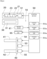
- FIG. 3 shows an imaging device 61 and a notification unit 65.
- the imaging device 61 images the bobbins 91 to generate bobbin images.
- the imaging device 61 is, for example, a camera that captures still images. However, the imaging device 61 may also be a video camera that captures moving images. If the imaging device 61 is a video camera, the imaging device 61 may generate images from moving images.
- the notification unit 65 notifies the operator of the determination result of the determination unit 50c.
- the notification unit 65 is, for example, a notification lamp or a notification buzzer.
- FIG. 3 shows the mounting state detection device 10.
- the mounting state detection device 10 detects the mounting states of the bobbins 91 on the bobbin holder 41 of the thread winding machine 1.
- the mounting state detection device 10 includes the control device 50, the imaging device 61, and the notification unit 65.
- the control device 50 performs the following processing as a component of the mounting state detection device 10.
- control unit 50a outputs data to the training unit 50b and the determination unit 50c for processing.
- the control unit 50a causes the storage unit 50d to store the data obtained by the training unit 50b and the determination unit 50c performing processing.
- the control unit 50a causes the storage unit 50d to store data (bobbin images) generated by the imaging device 61 performing imaging.
- the control unit 50a controls and operates the notification unit 65 in order to output the detected mounting states. Note that the traverse motor 51, the turret motor 53, the first bobbin holder motor 54, and the second bobbin holder motor 55 are further included as objects to be controlled by the control unit 50a.
- the training unit 50b constructs an estimation model by performing machine learning based on the bobbin images and the like stored in the storage unit 50d.
- the determination unit 50c performs determination processing regarding the mounting states of the bobbins 91 based on data externally input to the control device 50 and the estimation model constructed by the learning unit 50b and stored in the storage unit 50d.
- the determination result obtained through the determination processing of the determination unit 50c is output to the outside or stored in the storage unit 50d by the control unit 50a.
- the storage unit 50d stores data obtained through the processing of the control unit 50a, the training unit 50b, and the determination unit 50c, as described above.
- the mounting orientation of the bobbin 91 will be briefly described. Since the slit 91a is formed in the bobbin 91 as described above, the first side and the second side in the axial direction of the bobbin 91 are not symmetrical. Accordingly, it is necessary to attach the bobbins 91 to the bobbin holders 41 and 42 in the correct orientation. Specifically, the bobbins 91 need to be mounted on the bobbin holders 41 and 42 with the slits 91a facing away from the turret plate 40.
- a gap between adjacent bobbins 91 will be briefly described.
- a plurality of bobbins 91 are arranged side by side in the axial direction of the first bobbin holder 41 (second bobbin holder 42), and the thread 93 is wound around each bobbin 91.
- the traverse guide 23 and the thread guide (not shown) are also arranged side by side in the axial direction.
- the positions of the bobbins 91 are out of the appropriate range.
- the thread 93 cannot be properly wound.
- the mounting state detection device 10 may also detect only one of the mounting orientation of the bobbin 91 and the gap between adjacent bobbins 91. Alternatively, the mounting state detection device 10 may also detect the mounting state of a bobbin 91 other than these.
- the imaging devices 61 are arranged such that the lenses face the bobbin holders 41 and 42.
- the imaging devices 61 image the bobbins 91 at the standby position, but alternatively or additionally, the imaging devices 61 may image the bobbins 91 at the winding position.
- one imaging device 61 images two bobbins 91.
- the imaging devices 61 may also be configured to image one or three or more bobbins 91. Images generated by the imaging devices 61 imaging the bobbins 91 are called bobbin images.
- the imaging devices 61 image the bobbins 91 to generate a plurality of bobbin images while the second bobbin holder 42 is rotationally driven by the second bobbin holder motor 55.
- the slit 91a is formed only partially in the circumferential direction of the bobbin 91 in some cases. For this reason, in a situation where the part where the slit 91a is formed is the blind spot of the imaging device 61, there is a possibility that the slit 91a cannot be imaged.
- FIG. 4 conceptually shows processing for the training unit 50b to construct an estimation model using machine learning.
- the estimation model is constructed by performing machine learning of a bobbin image as training data and correct answer data indicating the range of the bobbin and the range of the slit in the bobbin image. Accordingly, this machine learning is supervised learning. Although the specific technique for performing machine learning is optional, deep learning is used in this embodiment. As a result, the training unit 50b can learn the relationship between the bobbin image and the range of the bobbin 91, and extract features for estimating a range of a bobbin 91 from a bobbin image.
- the training unit 50b can learn the relationship between the bobbin image and the range of the slit 91a, and extract features for estimating a range of a slit 91a from a bobbin image. As described above, the training unit 50b constructs an estimation model. The estimation model constructed by the training unit 50b is stored in the storage unit 50d.
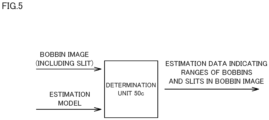
- the determination unit 50c generates estimation data indicating a range of a bobbin and a range of a slit in a bobbin image from a bobbin image generated by the imaging device 61 and the estimated model.
- FIG. 6 shows the estimation results of the estimation model.
- FIG. 6 is a diagram in which bobbin ranges 81 and slit ranges 82 are superimposed on a bobbin image.
- estimation model described above is an example, and the estimation model may also be constructed through another method. That is, instead of deep learning, machine learning may also be performed by the user specifying feature amounts related to the outline or the like of the bobbin 91. Also, the estimation model is an example, and for example, the orientation of the bobbin 91 may be used as the estimation model.
- the storage unit 50d stores the correct mounting orientation of the bobbin 91.
- the orientation in which the slit 91a is located on the first side is the correct mounting orientation of the bobbin 91.
- the storage unit 50d stores a threshold range, which is an appropriate range for the gap between adjacent bobbins 91. The threshold range is determined experimentally or empirically in advance.
- the determination unit 50c determines whether or not the mounting states of the bobbins 91 are appropriate. Specifically, based on the bobbin ranges 81 estimated by the estimation model, the determination unit 50c creates central virtual lines 81a indicating the center positions in the axial direction of the bobbin ranges 81. The determination unit 50c accesses the storage unit 50d and acquires the correct mounting orientation of the bobbin 91. Next, the determination unit 50c determines whether the slit ranges 82 are on the first side or the second side in the axial direction with respect to the central virtual lines 81a.
- the determination unit 50c determines that the mounting orientations of the bobbins 91 are correct if the slit ranges 82 are located on the first side of the central virtual lines 81a. Note that if the determination unit 50c has a storage device, the correct mounting orientation of the bobbin 91 may also be stored in the storage device of the determination unit 50c.
- the determination unit 50c compares two adjacent bobbin ranges 81 and calculates a length L1, which is the gap between the bobbin ranges 81.
- the determination unit 50c accesses the storage unit 50d and acquires a threshold range, which is an appropriate range for the gap between the adjacent bobbins 91.
- the determination unit 50c determines whether or not the length L1 satisfies the threshold range.
- the determination unit 50c determines that the gap between the bobbin ranges 81 is appropriate if the length L1 calculated from the bobbin image satisfies the threshold range. Note that FIG.
- FIG. 6 is a diagram for showing the processing of the determination unit 50c in an easily comprehensible manner, and the processing for superimposing the bobbin ranges 81 and the slit ranges 82 on the bobbin image may also be omitted. Note that if the determination unit 50c has a storage device, the threshold range may also be stored in the storage device of the determination unit 50c.
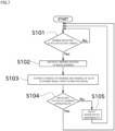
- the control device 50 determines whether or not the detection timing for detecting the bobbin mounting state has been reached (S101).
- the detection timing is after the start of the task of mounting the bobbins 91 on the bobbin holders 41 and 42 and before the start of the winding of the thread 93 by the thread winding machine 1.
- the control device 50 may also determine whether or not the detection timing has been reached based on the detection value of the sensor, or may determine that the detection timing has been reached when there is an instruction from an operator
- the control unit 50a of the control device 50 instructs the imaging devices 61 to image the bobbins 91 (S 102).
- the determination unit 50c of the control device 50 uses the bobbin images generated by the imaging devices 61 and the estimation model stored in the storage unit 50d to estimate the ranges of the bobbins 91 and the ranges of the slits 91a in the bobbin images as described above (S103).
- the determination unit 50c of the control device 50 determines whether or not the mounting states of the bobbins 91 are appropriate, as described above, based on the estimation results of the determination unit 50c (S104). If it is determined that the mounting states of the bobbins 91 are appropriate, the control unit 50a of the control device 50 returns to the processing of step S101 again. If it is determined that the mounting states of the bobbins 91 are not appropriate, the control unit 50a of the control device 50 controls the notification unit 65 to notify the operator of the abnormality (S105).
- the mounting state detection device 10 can detect whether or not the mounting states of the bobbins 91 are appropriate. In particular, detection accuracy can be increased by performing detection using an estimation model constructed through machine learning.
- FIG. 8 is a diagram showing an example of the hardware configuration of the control device 50.
- the control device 50 includes the above-described storage unit 50d (see FIG. 3 ), a processor 101, a communication interface 104, a display interface 105, and an input interface 107. These components are connected to a bus 115. Examples of the storage unit 50d include a ROM (Read Only Memory) 102, a RAM 103, an auxiliary storage device 120, and the like.
- ROM Read Only Memory
- the processor 101 is constituted by, for example, at least one integrated circuit.
- An integrated circuit can be constituted by, for example, at least one CPU, at least one GPU (Graphics Processing Unit), at least one ASIC (Application Specific Integrated Circuit), at least one FPGA (Field Programmable Gate Array), or a combination thereof.
- the processor 101 controls the operation of the control device 50 by executing various programs.
- the processor 101 reads out programs to be executed from the auxiliary storage device 120 or the ROM 102 to the RAM 103 upon receiving execution instructions for various programs.
- the RAM 103 functions as a working memory and temporarily stores various types of data necessary for program execution.
- ALAN Local Area Network
- an antenna and the like are connected to the communication interface 104.
- the control device 50 exchanges data with an external device via the communication interface 104.
- the external device includes, for example, a server.
- a display device 106 is connected to the display interface 105.
- the display interface 105 sends an image signal for displaying an image to display device 106 according to a command from the processor 101 or the like.
- the display device 106 is, for example, a liquid crystal display, an organic EL (Electro Luminescence) display, or other display. Note that the display device 106 may also be formed in one piece with the control device 50 or may be formed separately from the control device 50.
- the input device 108 is connected to the input interface 107.
- the input device 108 is, for example, a mouse, keyboard, touch panel, or other device capable of accepting user operations. Note that the input device 108 may be formed in one piece with the control device 50 or may be formed separately from the control device 50.
- the auxiliary storage device 120 is, for example, a storage medium such as a hard disk, a flash memory, and an SSD.
- the auxiliary storage device 120 stores, for example, a training data set 122, the above-described estimation model 124, a training program 126, and a mounting state detection program 128.
- the storage location for these is not limited to the auxiliary storage device 120, and they may also be stored in a storage region of the processor 101 (e.g., cache memory, etc.), the ROM 102, the RAM 103, an external device (e.g., a server), or the like.
- the training program 126 is a program for generating the estimation model 124 using the training data set 122.
- the training program 126 may also be provided as part of any program, instead of as a standalone program. In this case, the training processing performed by the training program 126 is realized in cooperation with any program. Even if a program does not include some of these modules, the program does not deviate from the gist of the training program 126 according to the present embodiment.
- some or all of the functions provided by the training program 126 may also be realized by dedicated hardware.
- the control device 50 may be included in the form of a so-called cloud service in which at least one server executes some of the processing of the training program 126.
- the mounting state detection program 128 is a program for determining the mounting states of the bobbins 91 on the bobbin holders 41 and 42 of the thread winding machine 1 using the trained estimation model 124.
- the mounting state detection program 128 may also be provided as a part of any program, instead of as a standalone program. In this case, the determination processing performed by the mounting state detection program 128 is realized in cooperation with any program. Even if a program does not include some of these modules, the program does not deviate from the gist of the mounting state detection program 128 according to the present embodiment.
- some or all of the functions provided by the mounting state detection program 128 may also be realized by dedicated hardware.
- the control device 50 may be included in the form of a so-called cloud service in which at least one server executes some of the processing of the mounting state detection program 128.
- FIG. 9 is a diagram showing an example of the training data set 122.
- the training data set 122 includes a plurality of pieces of training data 123.
- the number of pieces of training data 123 included in the training data set 122 is set as appropriate. As an example, the number of pieces of training data 123 is several tens to hundreds of thousands.
- Each piece of the training data 123 associates a training bobbin image showing a bobbin 91 with mounting state information representing the mounting state of the bobbin 91, as a label (correct answer value).
- FIG. 9 shows a combination of classification information and range information as an example of mounting state information.
- One or more combinations of classification information and range information are associated with one training bobbin image.
- Classification information is information that defines the type of an object shown in a bobbin image.
- the classification information is indicated by, for example, identification information that uniquely indicates the type of the object.
- the identification information is defined in advance for each object. As an example, identification information "1" indicates an object type "bobbin", and identification information "2" indicates an object type "slit”.
- the range information is information that defines the range of the object in the bobbin image with coordinate information.
- the coordinate information is defined, for example, by the center coordinates of the object, the horizontal width of the object, and the vertical width of the object.
- FIG. 10 is a diagram showing an example of the functional configuration of the control device 50.
- control device 50 includes a training unit 50b and a determination unit 50c as functional configurations. These functional configurations will be described in order below.
- FIG. 11 is a diagram conceptually showing the training processing performed by the training unit 50b.
- the training unit 50b executes training processing using the above-described training data set 122 (see FIG. 9 ), and generates an estimation model 124 that outputs the type of the object shown in the bobbin image and the range of the object shown in the bobbin image.
- a machine learning algorithm for realizing detection of the object type and the object range is not particularly limited.
- the machine learning algorithms include R-CNN (Regions with Convolutional Neural Network), Fast R-CNN, Faster R-CNN, SSD (Single Shot MultiBox Detector), YOLO (You Only Look Once), and the like.
- R-CNN Registered with Convolutional Neural Network
- Fast R-CNN Faster R-CNN
- SSD Single Shot MultiBox Detector
- YOLO You Only Look Once
- the estimation model 124 is configured to receive input of a training bobbin image defined in the training data 123.
- the estimation model 124 is constituted by, for example, a classification model 125A and a range prediction model 125B.
- the classification model 125A and the range prediction model 125B may each have a separate network structure, or may be configured to share some of the network structure.
- the classification model 125A receives input of a training bobbin image and outputs the type of an object included in the training bobbin image as an estimation result.
- the range prediction model 125B receives input of a training bobbin image and outputs range information of an object included in the training bobbin image as an estimation result.
- the range information is defined by a combination of "cx" and “cy” indicating the center coordinates of the object, "w” indicating the horizontal width of the object, and "h” indicating the vertical width of the object.
- a bounding box means a rectangular frame that roughly indicates the range of each object shown in the bobbin image.
- the number of pieces of classification information output by the classification model 125A is proportional not only to the number of classification objects and the number of grid cells in the training bobbin image, but also to the number of set bounding boxes.
- the number of pieces of range information output by the range prediction model 125B is proportional not only to the number of grid cells but also to the number of bounding boxes that are set.
- the training unit 50b inputs the training bobbin image defined in the training data 123 to the estimation model 124. As a result, the training unit 50b acquires the classification information and the range information as the estimation results of the estimation model 124. Thereafter, the training unit 50b refers to the mounting state information serving as the correct answer value defined in the training data 123, and calculates the error between the mounting state information and the estimation result of the estimation model 124. Next, the training unit 50b updates the internal parameters (for example, weight and bias) of the estimation model 124 such that the error becomes smaller. Updating of the internal parameters is realized through error backpropagation, for example.
- the training unit 50b repeatedly performs processing for updating the internal parameters of the estimation model 124 for each piece of training data 123 included in the training data set 122.
- the estimation model 124 outputs more accurate estimation results as learning progresses.
- the estimation model 124 receives input of a bobbin image and outputs a score indicating the likelihood that the classification object is shown, and range information indicating coordinate information of the classification object for each grid cell.
- the training unit 50b does not need to use all the training data 123 included in the training data set 122 for the training processing, and may use some of the training data 123 included in the training data set 122 to generate the estimation model 124.
- the remaining training data 123 is used, for example, for evaluation of the estimation model 124 and the like.
- FIG. 12 is a diagram conceptually showing the mounting state determination processing performed by the determination unit 50c.
- the determination unit 50c acquires the estimation model 124 generated by the training unit 50b from a storage location.
- the estimation model 124 may be acquired from the storage unit 50d described above, or an external device.
- the determination unit 50c acquires a determination bobbin image from the imaging device 61 by imaging the bobbins 91 mounted on the bobbin holders 41 and 42.
- the determination bobbin image is an image used for determining whether or not the bobbins 91 are mounted normally on the bobbin holders 41 and 42.
- the determination unit 50c inputs the acquired determination bobbin image to the estimation model 124 and acquires the mounting state information output from the estimation model 124. Thereafter, the determination unit 50c determines whether or not the bobbins 91 are mounted normally on the bobbin holders 41 and 42 based on the mounting state information.
- the above-described classification information and the above-described range information are shown as the mounting state information output from the estimation model 124.
- the determination unit 50c integrates the classification information and the range information output from the estimation model 124, and detects whether or not there is a classification target object in the estimation image, and the range information of the object. More specifically, if there are two types of classification objects, namely the bobbin 91 and the slit 91a, the classification information includes a score indicating the likelihood that the bobbin 91 is present and a score indicating the likelihood that the slit 91a is present for each grid cell. The determination unit 50c determines that the bobbin 91 is shown in the grid cell for which the score for the bobbin 91 exceeds a predetermined value.
- the determination unit 50c determines that the slit 91a is shown in the grid cell for which the score for the slit 91a exceeds a predetermined value. Thereafter, the determination unit 50c refers to the range information corresponding to those grid cells, and specifies the bobbin range indicating the range of the bobbin 91 in the determination bobbin image and the slit range indicating the range of the slit 91a in the determination bobbin image.
- the determination unit 50c detects various mounting abnormalities of the bobbin 91 based on the specified bobbin range and slit range.
- the determination unit 50c determines whether or not the mounting orientations of the bobbins 91 on the bobbin holders 41 and 42 are normal. A determination is made regarding whether or not the mounting orientations of the bobbins 91 are normal, for example, based on the positional relationships between the bobbin ranges and the slit ranges. More specifically, the determination unit 50c determines whether the relative position of the slit range with respect to the bobbin range is closer to the above-described first side (see FIG. 6 ) or the above-described second side (see FIG. 6 ).
- the determination unit 50c determines that the mounting orientation of the bobbin 91 is normal. On the other hand, if the position of the slit 91a with respect to the bobbin 91 is on the second side, the determination unit 50c determines that the mounting orientation of the bobbin 91 is abnormal.
- the determination unit 50c determines whether or not the interval between the bobbins 91 included in the determination bobbin image is normal. A determination is made regarding whether or not the interval is normal, for example, based on the positional relationship between adjacent bobbin ranges among the bobbin ranges in the determination bobbin image. More specifically, the determination unit 50c calculates the distance between the adjacent bobbin ranges, and based on the distance, calculates the above-described length L1 (see FIG. 6 ), which is the interval between the adjacent bobbins 91. If the length L1 is within the predetermined threshold range, the determination unit 50c determines that the interval between adjacent bobbins 91 is normal. On the other hand, if the length L1 is not included in the predetermined threshold range, the determination unit 50c determines that the interval between adjacent bobbins 91 is abnormal.
- the output mode of the determination result by the determination unit 50c is not particularly limited.
- the determination unit 50c outputs a warning including the type of mounting abnormality that has occurred.
- the warning may, for example, be displayed as a message on the above-described display device 106, may be output by voice, or may be stored in the storage unit 50d as a log.
- the training unit 50b and the determination unit 50c were provided in the same thread winding machine 1. However, the training unit 50b and the determination unit 50c do not necessarily need to be provided in the same thread winding machine 1. As an example, the training unit 50b may also be provided in a different device.
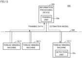
- FIG. 13 is a diagram showing an example of the device configuration of a mounting state determination system 500 according to this modified example.
- the mounting state determination system 500 includes one or more thread winding machines 1 and one or more information processing devices 200.
- the mounting state determination system 500 is constituted by three thread winding machines 1A to 1C and one information processing device 200.
- the thread winding machines 1A to 1C and the information processing device 200 are connected to the same network NW and are configured to be able to communicate with each other.
- the thread winding machines 1 and the information processing device 200 may also be communicatively connected by wire or wirelessly.
- the information processing device 200 is a desktop personal computer, a notebook personal computer, a tablet terminal, or another information processing terminal.
- the training unit 50b is provided in the information processing device 200. Also, the determination unit 50c is provided in the thread winding machine 1C.
- the information processing device 200 collects the above-described training data 123 (see FIG. 9 ) from the thread winding machines 1 (e.g., the thread winding machines 1A and 1B) connected to the network NW.
- the training unit 50b of the information processing device 200 executes training processing using the training data 123 collected from all of the thread winding machines 1, and generates the above-described estimation model 124. Since the function of the training unit 50b is as described above, description thereof will not be repeated.
- the information processing device 200 transmits the generated estimation model 124 to the thread winding machine 1 (e.g., the thread winding machine 1C).
- the determination unit 50c of the thread winding machine 1C uses the estimation model 124 to detect mounting abnormalities of the bobbins 91 mounted on the bobbin holders 41 and 42 of the thread winding machines 1. Since the function of the determination unit 50c is as described above, description thereof will not be repeated.
- the above-described mounting state detection device 10 specifies the bobbin range and the slit range in the determination bobbin image, and detects a mounting abnormality of the bobbins 91 based on the bobbin range and the slit range.
- the mounting state detection device 10 directly detects the type of mounting abnormality of the bobbins 91 from the determination bobbin image. Note that other respects such as the hardware configuration of the mounting state detection device 10 are as described above, and therefore description thereof will not be repeated.
- FIG. 14 is a diagram showing an example of the training data set 122A.
- the training data set 122A includes a plurality of pieces of training data 123A.
- the number of pieces of training data 123A included in the training data set 122A is set as appropriate. As an example, the number of pieces of training data 123A is several tens to several hundreds of thousands.
- Each piece of the training data 123A associates a training bobbin image showing a bobbin 91 with mounting state information representing the mounting state of the bobbin 91, as a label (correct answer value).
- FIG. 14 shows the types of mounting abnormalities of the bobbins 91 as an example of the mounting state information.
- the type of label defined in the training data set 122A may be one type or a plurality of types.
- an abnormality "A" indicating that the mounting orientation of the bobbin 91 is incorrect, and an abnormality "B” indicating that the interval between the bobbins 91 is incorrect are shown as labels for mounting abnormalities.
- FIG. 15 is a diagram conceptually showing training processing performed by the training unit 50e in this modified example.
- the training unit 50e executes training processing using the above-described training data set 122A (see FIG. 14 ), and generates an estimation model 124A for identifying a mounting abnormality of a bobbin 91.
- a machine learning algorithm employed for training processing is not particularly limited, and for example, deep learning, a convolutional neural network (CNN), a full-layer convolutional neural network (FCN), a support vector machine, or the like can be employed thereas.
- CNN convolutional neural network
- FCN full-layer convolutional neural network
- support vector machine or the like
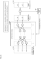
- the estimation model 124A is constituted by an input layer X, an intermediate layer H, and an output layer Y.
- the input layer X is configured to receive input of the bobbin image of the training data 123A.
- the input layer X is constituted by, for example, N units x 1 to x N (N is a natural number).
- the number of units constituting the input layer X is the same as the number of dimensions of input information.
- the input layer X is constituted by N units.
- the feature amount extracted from the bobbin image may be input to the input layer X.
- the input layer X is configured such that the number of units is the same as the number of dimensions of the feature amount after feature extraction.
- Each unit constituting the input layer X outputs input data to each unit of the first layer of the intermediate layer H.
- the intermediate layer H is constituted by one layer or a plurality of layers.
- the intermediate layer H is constituted by L layers (L is a natural number).
- Each layer of the intermediate layer H includes a plurality of units.
- the number of units in each layer of the intermediate layer H may be the same or different.
- the first layer of the intermediate layer H is constituted by Q units h A1 to h AQ (Q is a natural number).
- the final layer of the intermediate layer H is constituted by R units h L1 to h LR (R is a natural number).
- Each unit constituting each layer of the intermediate layer H is connected to each unit of the previous layer and each unit of the next layer.
- Each unit in each layer receives an output value from each unit in the previous layer, multiplies the output value by a weight, accumulates the multiplication results, adds (or subtracts) a predetermined bias to (or from) the accumulation result, inputs the addition result (or subtraction result) to a predetermined function (e.g., a sigmoid function), and outputs the output value of the function to each unit of the next layer.
- a predetermined function e.g., a sigmoid function
- the output layer Y outputs an estimation result corresponding to the input bobbin image.
- the output layer Y is constituted by units y 1 and y 2 , for example.
- the units y 1 and y 2 are also referred to as units y.
- Each of the units y is connected to the units h L1 to h LR in the final layer of the intermediate layer H.
- Each unit y receives an output value from each unit of the final layer of the intermediate layer H, multiplies each output value by a weight, integrates the multiplication results, adds (or subtracts) a predetermined bias to (or from) the integration result, inputs the addition result (or subtraction result) to a predetermined function (e.g., a sigmoid function), and outputs the output result of the function as an output value.
- a predetermined function e.g., a sigmoid function
- the number of units constituting the output layer Y is determined according to the number of types of mounting abnormalities defined in the training data 123A. As an example, in the case of detecting mounting abnormalities "A" and "B", the number of units constituting the output layer Y is two, namely the units y 1 and y 2 .
- the unit y 1 is configured to output a score "sa” that indicates the likelihood that the mounting abnormality "A” has occurred.
- the unit y 2 is configured to output a score "sb" indicating the likelihood that the mounting abnormality "B" has occurred.
- the estimation model 124A is configured to output a plurality of scores, but one estimation model may also be configured to output one score.
- the first estimation model may be configured to output a score "sa” for an abnormality type "A”
- the second estimation model may be configured to output a score "sb” for an abnormality type "B”.
- the training unit 50e inputs the bobbin image defined in the first piece of training data 123A to the estimation model 124A. Next, the training unit 50e obtains the estimation results "sa” and “sb” output from the estimation model 124A and correct answer scores "sa'" and "sb'” corresponding to the abnormality type associated with the first piece of training data 123A.
- the training unit 50e calculates an error "Z” between output results "sa” and “sb” of the estimation model 124A and the correct answer scores "sa'" and “sb”'.
- An error “Z” is calculated, for example, based on the following formula (1).
- Z sa ⁇ sa ′ 2 + sb ⁇ sb ′ 2 / 2
- the training unit 50e updates the various parameters (for example, weights and biases) included in the estimation model 124A such that the error "Z" becomes smaller. Updating of the parameters is realized, for example, through the error backpropagation method.
- the training unit 50e repeatedly updates the internal parameters of the estimation model 124A for each piece of training data 123A included in the training data set 122A. As a result, the estimation model 124A outputs more accurate estimation results as training progresses.
- the training unit 50e does not need to use all of the training data 123A included in training data set 122A for training processing, and may use some of the training data 123A included in the training data set 122A to generate the estimation model 124A.
- the remaining training data 123A is used, for example, for evaluation of the estimation model 124A.
- FIG. 16 is a diagram conceptually showing the mounting abnormality determination processing performed by the determination unit 50f according to the present modification.
- the determination unit 50f acquires the estimation model 124A generated by the training unit 50e from a storage location.
- the estimation model 124A may be acquired from the storage unit 50d described above, or an external device.
- the determination unit 50f acquires a determination bobbin image from the imaging device 61 by imaging the bobbins 91 mounted on the bobbin holders 41 and 42. Thereafter, the determination unit 50f inputs the determination bobbin image to the estimation model 124A. As a result, the estimation model 124A outputs a score indicating the likelihood that a mounting abnormality of the bobbin 91 has occurred, to the abnormality type.
- the estimation model 124A outputs, for example, a score "sa” indicating the likelihood that the mounting abnormality "A” has occurred, and a score "sb” indicating the likelihood that the mounting abnormality "B" has occurred, as the estimation result.
- the determination unit 50f determines the type of mounting abnormality that has occurred based on the scores "sa" and "sb". As an example, the determination unit 50f determines that the bobbin 91 has an abnormal mounting orientation if the score "sa" exceeds the first threshold.
- the first threshold may also be pre-set or set as appropriate by the user.
- the determination unit 50f determines that the bobbin 91 has an abnormal interval if the score "sb" exceeds the second threshold.
- the second threshold may also be preset or set as appropriate by the user. Also, the second threshold may be the same as the first threshold, or may be different from the first threshold.
- the determination unit 50f determines that the bobbins 91 are mounted normally on the bobbin holders 41 and 42.
- the output mode of the determination result by the determination unit 50f is not particularly limited.
- the determination unit 50f outputs a warning including the type of mounting abnormality that has occurred.
- the warning may, for example, be displayed as a message on the above-described display device 106, output as sound by the above-described notification unit 65, or stored as a log in the storage unit 50d.
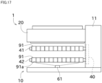
- FIG. 17 is a side view of the thread winding machine 1 of the fourth modified example.
- one imaging device 61 images two bobbins 91.
- one imaging device 61 images all of the bobbins 91 mounted on the second bobbin holder 42.
- the imaging device 61 of the fourth modified example is a wide-angle camera and can image a wide range.
- the imaging device 61 is arranged at a certain distance from the bobbins 91.
- the imaging device 61 of the fourth modified example may also be arranged at a position spaced apart from the thread winding machine 1.
- FIG. 18 is a side view of the thread winding machine 1 of the fifth modified example.
- the position of the imaging device 61 is fixed.
- the imaging device 61 can travel along the axial direction of the second bobbin holder 42.
- a rail 62 and a cart 63 are provided.
- the rail 62 is formed along the axial direction of the second bobbin holder 42.
- the cart 63 can travel along the rail 62.
- the imaging device 61 is arranged on the cart 63. This configuration allows the imaging device 61 to travel along the axial direction of the second bobbin holder 42.
- a large number of bobbins 91 can be imaged using one imaging device 61 by causing the imaging device 61 to travel.
- the imaging device 61 may image the bobbins 91 while traveling, or may image the bobbins 91 after traveling and stopping at predetermined positions.
- one cart 63 is shown in FIG. 18 , a plurality of carts 63 may be provided.
- FIG. 19 is a side view of the thread winding machine 1 of the sixth modified example.
- the mounting state detection device 10 detects whether or not the mounting state of the bobbins 91 is appropriate when all of the bobbins 91 are mounted on the second bobbin holder 42.
- the mounting state detection device 10 detects whether or not the mounting states of the bobbins 91 are appropriate.
- the imaging device 61 is arranged near the insertion end of the second bobbin holder 42.
- the insertion end is the end on the side where the second bobbin holder 42 is inserted, and in other words, is the end on the side opposite to the turret plate 40.
- the bobbin 91 inserted from the insertion end is slid, and then the next bobbin 91 is inserted.
- the imaging device 61 is arranged at a position at which the bobbin 91 inserted into the insertion end can be imaged.
- the imaging device 61 images the bobbin 91 when the bobbin 91 is inserted. All of the bobbins 91 inserted onto the second bobbin holder 42 pass through the insertion end at least during insertion. Also, the mounting orientation does not change after the bobbin 91 is inserted. Accordingly, by imaging the bobbins 91 at the time of insertion and performing determination through the method of the above embodiment, it is possible to detect whether or not the insertion orientations of all of the bobbins 91 are appropriate.
- the number of imaging devices 61 can be reduced, and therefore there is a possibility that lower cost and space saving can be achieved compared to the above embodiment.
- FIG. 20 is a front view of the thread winding machine 1 of the seventh modified example.
- the mounting state detection device 10 images the bobbins 91 from one direction to generate a bobbin image.
- bobbin images are generated by imaging the bobbins 91 from two directions.
- the imaging devices 61 are arranged in different directions with respect to the bobbins 91.
- bobbin images of various locations on the outer peripheral surface of the bobbin 91 can be created, and therefore the mounting states of the bobbins 91 can be detected with higher accuracy.
- the slit 91a can be detected with high accuracy.
- the seventh modified example can be applied to any of the above embodiment and the fourth to sixth modified examples.
- the bobbins 91 may be imaged from two directions by moving the imaging device 61.
- the mounting state detection device 10 of the embodiment and the modified examples detects the mounting states of the bobbins 91 on the bobbin holders 41 and 42.
- the mounting state detection device 10 includes the imaging device 61, the training unit 50b, the storage unit 50d, and the determination unit 50c.
- the imaging device 61 images a range including the bobbins 91 to generate a bobbin image.
- the training unit 50b constructs an estimation model by performing machine learning using the bobbin image and the ranges of the bobbins 91 in the bobbin image as training data.
- the storage unit 50d stores the estimation model constructed by the training unit 50b.
- the determination unit 50c generates the ranges of the bobbins 91 based on the bobbin image generated by the imaging device 61 and the estimation model stored in the storage unit 50d, and determines the mounting states of the bobbins 91 based on the ranges of the bobbins 91.
- the slits 91a are formed in the bobbins 91.
- the storage unit 50d stores the correct mounting orientations of the bobbins 91.
- the training unit 50b constructs an estimation model by performing machine learning using the bobbin image and the ranges of the bobbins 91 and the ranges of the slits 91a in the bobbin image as training data.
- the determination unit 50c Based on the bobbin image and the estimation model stored in the storage unit 50d, the determination unit 50c generates the ranges of the bobbins 91 and the ranges of the slits 91a.
- the determination unit 50c determines whether or not the mounting orientations of the bobbins 91 are correct based on the ranges of the bobbins 91, the ranges of the slits 91a, and the correct mounting orientations of the bobbins 91 stored in the storage unit 50d.
- a plurality of bobbins 91 are arranged side by side in the bobbin holders 41 and 42.
- the storage unit 50d stores an appropriate range of the gap between adjacent bobbins 91. Based on the ranges of the plurality of bobbins 91 generated by the determination unit 50c and the appropriate range of the gap between adjacent bobbins 91 stored in the storage unit 50d, the determination unit 50c determines whether or not the gap between the adjacent bobbins 91 is within the appropriate range.
- the gap between adjacent bobbins 91 can be accurately distinguished from other similar objects, and therefore it is possible to accurately determine whether or not the gap between the bobbins 91 is within an appropriate range.
- the mounting state detection device 10 of the above-described embodiment and modified examples includes a notification unit 65 that performs notification when the determination unit 50c determines that the mounting states of the bobbins 91 are abnormal.
- the operator can be notified of the abnormality in the mounting states of the bobbins.
- the imaging device 61 images the range including the bobbins 91 after the start of the task of mounting the bobbins 91 on the bobbin holders 41 and 42 and before the start of the winding of the thread 93 by the thread winding machine 1.
- a plurality of bobbins 91 are arranged side by side in the bobbin holders 41 and 42.
- a plurality of imaging devices 61 are arranged along the axial direction of the second bobbin holder 42. The imaging devices 61 generate bobbin images including one or more bobbins 91.
- a plurality of bobbins 91 are arranged side by side in the bobbin holders 41 and 42.
- One imaging device 61 generates a bobbin image including all of the bobbins 91.
- a plurality of bobbins 91 are arranged side by side in the bobbin holders 41 and 42.
- the imaging device 61 can travel along the axial direction of the second bobbin holder 42. After generating the bobbin image including the bobbin 91, the imaging device 61 travels to generate bobbin image including another bobbin 91.
- a plurality of bobbins 91 are arranged side by side by inserting the bobbins 91 from the insertion ends of the bobbin holders 41 and 42 and sliding the bobbins 91.
- the imaging device 61 generates bobbin images for all the bobbins 91 by sequentially imaging the bobbins 91 inserted from the insertion ends.
- the mounting state detection device 10 of the seventh modified example includes a plurality of imaging devices 61.
- the imaging devices 61 image the bobbins 91 from a plurality of directions.
- the determination unit 50c determines the mounting states of the bobbins 91 based on a plurality of bobbin images imaged from a plurality of directions.
- the determination is performed based on the result of imaging a wide range in the circumferential direction of the bobbins 91, and therefore the detection accuracy can be increased.
- the imaging device 61 images the bobbins 91 a plurality of times while the bobbins 91 are rotated using the axial direction of the bobbin holders 41 and 42 as the center of rotation, thereby generating a plurality of bobbin images.
- the determination unit 50c determines the mounting state of the bobbin 91 based on a plurality of bobbin images for one bobbin 91.
- the determination is performed based on the result of imaging the entire bobbin 91 in the circumferential direction, and therefore the detection accuracy can be increased.
- the traverse device 21 of the above embodiment is of a cam drum type, it may have a different configuration as long as the traverse guide 23 can be moved back and forth in the winding width direction.
- a belt-type traverse device can be used instead of the traverse device 21, a belt-type traverse device can be used instead of the traverse device 21, a belt-type traverse device can be used instead of the traverse device 21, a belt-type traverse device can be used.
- the present embodiment includes the following disclosures.
- a mounting state detection device having the following configuration. That is, the mounting state detection device detects a mounting state of a bobbin on a bobbin holder of a thread winding machine.
- the mounting state detection device includes an imaging device, a training unit, a storage unit, and a determination unit.
- the imaging device images a range including the bobbin to generate a bobbin image.
- the training unit constructs an estimation model by performing machine learning using the bobbin image and the range of the bobbin in the bobbin image as training data.
- the storage unit stores the estimation model constructed by the training unit.
- the determination unit generates the range of the bobbin based on the bobbin image generated by the imaging device and the estimation model stored in the storage unit, and determines the mounting state of the bobbin based on the range of the bobbin.
- the mounting state detection device described above has the following configuration. That is, a slit is formed in the bobbin.
- the storage unit stores the correct mounting orientation of the bobbin.
- the training unit constructs an estimation model by performing machine learning using the bobbin image and the range of the bobbin and the range of the slit in the bobbin image as training data.
- the determination unit generates the range of the bobbin and the range of the slit based on the bobbin image and the estimation model stored in the storage unit.
- the determination unit determines whether or not the mounting orientation of the bobbin is correct based on the range of the bobbin, the range of the slit, and the correct mounting orientation of the bobbin stored in the storage unit.
- the mounting state detection device described above has the following configuration. That is, a plurality of the bobbins are arranged side by side in the bobbin holder.
- the storage unit stores an appropriate range of a gap between the adjacent bobbins. It is preferable that the determination unit determines whether or not the gap between the adjacent bobbins is within an appropriate range based on the ranges of the plurality of bobbins generated by the determination unit and the appropriate range of the gap between the adjacent bobbins stored in the storage unit.
- the mounting state detection device described above further includes a notification unit that performs notification when the determination unit determines that the mounting state of the bobbin is abnormal.
- the operator can be notified of the abnormality in the mounting state of the bobbin.
- the imaging device images the range including the bobbin after the start of a task of mounting the bobbin on the bobbin holder and before the start of thread winding by the thread winding machine.
- the mounting state detection device described above has the following configuration. That is, a plurality of the bobbins are arranged side by side in the bobbin holder. A plurality of the imaging devices are arranged along the axial direction of the bobbin holder. The imaging devices generate the bobbin images including one or more of the bobbins.
- the mounting state detection device described above has the following configuration. That is, a plurality of the bobbins are arranged side by side in the bobbin holder. One imaging device generates the bobbin image including all of the bobbins.
- the mounting state detection device described above has the following configuration. That is, a plurality of the bobbins are arranged side by side in the bobbin holder.
- the imaging device can travel along the axial direction of the bobbin holder. After generating the bobbin image including the bobbin, the imaging device travels and generate the bobbin image including another bobbin.
- the mounting state detection device described above has the following configuration. That is, the plurality of bobbins are arranged side by side by inserting the bobbins from the insertion end of the bobbin holder and sliding the bobbins.
- the imaging device sequentially images the bobbins inserted from the insertion end to generate the bobbin images for all of the bobbins.
- the mounting state detection device described above has the following configuration. That is, the mounting state detection device includes a plurality of the imaging devices.
- the imaging device images the bobbin from a plurality of directions.
- the determination unit determines the mounting state of the bobbin based on a plurality of bobbin images imaged from a plurality of directions.
- the detection accuracy can be increased.
- the mounting state detection device described above has the following configuration. That is, the imaging device images the bobbin a plurality of times while the bobbin is rotating with the axial direction of the bobbin holder as a center of rotation, to generate a plurality of the bobbin images.
- the determination unit determines the mounting state of the bobbin based on the plurality of bobbin images for the one bobbin.
Landscapes
- Engineering & Computer Science (AREA)
- Theoretical Computer Science (AREA)
- Physics & Mathematics (AREA)
- General Physics & Mathematics (AREA)
- Computer Vision & Pattern Recognition (AREA)
- Multimedia (AREA)
- Software Systems (AREA)
- Quality & Reliability (AREA)
- Computing Systems (AREA)
- Medical Informatics (AREA)
- Evolutionary Computation (AREA)
- Signal Processing (AREA)
- Artificial Intelligence (AREA)
- General Engineering & Computer Science (AREA)
- Mathematical Physics (AREA)
- Data Mining & Analysis (AREA)
- Health & Medical Sciences (AREA)
- Databases & Information Systems (AREA)
- General Health & Medical Sciences (AREA)
- Replacing, Conveying, And Pick-Finding For Filamentary Materials (AREA)
Abstract
Provided is a mounting state detection device (10) capable of accurately determining whether or not a mounting state of a bobbin is appropriate. The mounting state detection device (10) includes a control device (50) and an imaging device (61) configured to be able to image a bobbin mounted on a bobbin holder of a thread winding machine. The control device (50) executes processing for acquiring an estimation model (124) generated by performing machine learning of a plurality of pieces of training data (123). Each of the plurality of pieces of training data (123) associates a training bobbin image showing the bobbin with mounting state information representing a mounting state of a bobbin, as a label. The control device (50) further executes processing for acquiring a determination bobbin image from the imaging device (61) by imaging the bobbin mounted on the bobbin holder, and processing for determining whether or not the bobbin is mounted normally on the bobbin holder based on the mounting state information output from the estimation model (124) by inputting the determination bobbin image to the estimation model (124).
Description
- The present invention mainly relates to a device for detecting a mounting state of a bobbin on a bobbin holder.
-
Japanese Utility Model Laid-Open No. H4-97769 -
Japanese Utility Model Laid-Open No. H4-97769 - A method of detecting a slit in a paper tube using a photoelectric sensor as in
Patent Document 1 may result in erroneous detection due to, for example, unevenness of the paper tube, a gap between paper tubes, foreign matter, and the like. In addition to slit detection, erroneous detection may also similarly occur when detecting various events related to the bobbin mounting state, such as the size of a gap between bobbins. Accordingly, there has been demand for a configuration according to which it is possible to accurately determine whether or not the mounting state of a bobbin is appropriate. - The present disclosure has been made in view of the above circumstances, and a main object thereof is to provide a mounting state detection device, a mounting state detection method, and a mounting state detection program capable of accurately determining whether or not the mounting state of the bobbin is appropriate.
- In one example of the present disclosure, a mounting state detection device is provided. The mounting state detection device includes a control device and an imaging device configured to be able to image a bobbin mounted on a bobbin holder of a thread winding machine. The control device executes processing for acquiring an estimation model generated by performing machine learning of a plurality of pieces of training data. Each of the plurality of pieces of training data associates a training bobbin image showing a bobbin with mounting state information representing a mounting state of the bobbin, as a label. The control device further executes processing for acquiring a determination bobbin image from the imaging device by imaging the bobbin mounted on the bobbin holder, and processing for determining whether or not the bobbin is mounted normally on the bobbin holder based on the mounting state information output from the estimation model by inputting the determination bobbin image to the estimation model.
- This mounting state detection device uses an estimation model that has learned a relationship between the training bobbin image and the mounting state information. As a result, the mounting state detection device can acquire the mounting state information of the bobbin by inputting the determination bobbin image to the estimation model, and can determine the mounting state of the bobbin.
- In one example of the present disclosure, in the determining processing, a determination is made regarding whether or not a mounting orientation of the bobbin on the bobbin holder is normal.
- Thus, the mounting state detection device can detect a specific mounting abnormality of the bobbin.
- In one example of the present disclosure, a slit is formed in the bobbin. The mounting state information serving as the label includes a bobbin range indicating a range of a bobbin in the training bobbin image and a slit range indicating a range of a slit in the training bobbin image. The estimation model receives input of the determination bobbin image and outputs the bobbin range in the determination bobbin image and the slit range in the determination bobbin image as mounting state information. A determination is made regarding whether or not the mounting orientation is normal based on a positional relationship between the bobbin range and the slit range output from the estimation model.
- By focusing on the positional relationship between the bobbin range and the slit range in the bobbin image, the mounting state detection device can more accurately determine whether or not the mounting orientation of the bobbin on the bobbin holder is normal.
- In one example of the present disclosure, a plurality of bobbins are arranged side by side on the bobbin holder. In the determining processing, a determination is made regarding whether or not an interval between the bobbins included in the determination bobbin image is normal.
- Thus, the mounting state detection device can detect a specific mounting abnormality of the bobbins.
- In one example of the present disclosure, the mounting state information serving as the label includes a bobbin range indicating a range of a bobbin in the training bobbin image. The estimation model receives input of the determination bobbin image and outputs the bobbin range for each bobbin included in the determination bobbin image. A determination is made regarding whether or not the interval is normal based on the positional relationship between adjacent bobbin ranges among the bobbin ranges output from the estimation model.
- The mounting state detection device can more accurately determine whether or not the interval between adjacent bobbins is normal by focusing on an interval between the bobbin ranges in the bobbin image.
- In one example of the present disclosure, the control device further executes processing for performing notification of a mounting abnormality of the bobbin if it is determined that the bobbin is not mounted normally on the bobbin holder.
- Thus, the mounting state detection device can inform an operator of the abnormality in the mounting state of the bobbin.
- In one example of the present disclosure, the imaging device images the bobbin after the start of a task of mounting the bobbin on the bobbin holder and before the start of thread winding by the thread winding machine.
- As a result, the mounting state detection device can determine the mounting state of the bobbin before a problem occurs due to incorrect mounting of the bobbin.
- In one example of the present disclosure, a plurality of the bobbins are arranged side by side on the bobbin holder. A plurality of the imaging devices are arranged along an axial direction of the bobbin holder. The imaging devices generate the determination bobbin image including one or more of the bobbins.
- As a result, even if a plurality of bobbins are arranged side by side on the bobbin holder, the mounting states of these bobbins can be accurately detected by using a plurality of imaging devices.
- In one example of the present disclosure, a plurality of the bobbins are arranged side by side on the bobbin holder. One imaging device generates the determination bobbin image including all of the bobbins.
- As a result, even if a plurality of bobbins are arranged side by side on the bobbin holder, it is possible to accurately detect the mounting state of these bobbins while suppressing the number of imaging devices by using a wide-angle imaging device capable of imaging the plurality of bobbins together.
- In one example of the present disclosure, a plurality of the bobbins are arranged side by side on the bobbin holder. The imaging device is configured to be able to travel along an axial direction of the bobbin holder. The imaging device travels after generating the determination bobbin image including one of the bobbins, and generates the determination bobbin image including another of the bobbins.
- As a result, even if a plurality of bobbins are arranged side by side on the bobbin holder, it is possible to accurately detect the mounting states of the bobbins while suppressing the number of imaging devices by causing the imaging device to travel along the axial direction of the bobbin holder.
- In an example of the present disclosure, a plurality of the bobbins are arranged side by side by inserting the bobbins from an insertion end of the bobbin holder and sliding the bobbins. The imaging device sequentially images the bobbins inserted from the insertion end to generate the determination bobbin images for all of the bobbins.
- As a result, even if a plurality of bobbins are arranged side by side on the bobbin holder, it is possible to accurately detect the mounting states of these bobbins while suppressing the number of imaging devices by sequentially imaging the bobbins when the bobbins are inserted.
- An example of the present disclosure includes a plurality of the imaging devices. The imaging devices image the bobbin from a plurality of directions. A determination is made regarding whether or not the bobbin is mounted normally on the bobbin holder based on a plurality of determination bobbin images imaged from a plurality of directions.
- Since the determination is based on the result of imaging a wide range in the circumferential direction of the bobbin, detection accuracy can thus be increased.
- In one example of the present disclosure, the imaging device generates a plurality of the determination bobbin images by imaging the bobbin a plurality of times while the bobbin rotates using an axial direction of the bobbin holder as a center of rotation. A determination is made regarding whether or not the bobbin is mounted normally on the bobbin holder based on the plurality of determination bobbin images.
- Since the determination is based on the result of imaging the entire bobbin in the circumferential direction, detection accuracy can be increased.
- In another example of the present disclosure, a mounting state detection method to be executed by a mounting state detection device is provided. The mounting state detection device includes an imaging device configured to be able to image a bobbin mounted on a bobbin holder of a thread winding machine. The mounting state detection method includes a step of acquiring an estimation model generated by performing machine learning of a plurality of pieces of training data. Each of the plurality of pieces of training data associates a training bobbin image showing a bobbin with mounting state information representing the mounting state of the bobbin, as a label. The mounting state detection method further includes a step of acquiring a determination bobbin image from the imaging device by imaging the bobbin mounted on the bobbin holder, and a step of determining whether or not the bobbin is mounted normally on the bobbin holder based on the mounting state information output from the estimation model by inputting the determination bobbin image to the estimation model.
- This mounting state detection method uses an estimation model that has learned the relationship between the training bobbin image and the mounting state information. As a result, with the mounting state detection method, it is possible to acquire the mounting state information of the bobbin by inputting the determination bobbin image to the estimation model, and it is possible to determine the mounting state of the bobbin.
- Another example of the present disclosure provides a mounting state detection program to be executed by a mounting state detection device. The mounting state detection device includes an imaging device configured to be able to image a bobbin mounted on a bobbin holder of a thread winding machine. The mounting state detection program causes the mounting state detection device to execute a step of acquiring an estimation model generated by performing machine learning of a plurality of pieces of training data. Each of the plurality of pieces of training data associates a training bobbin image showing a bobbin, with mounting state information representing the mounting state of the bobbin, as a label. The mounting state detection program further causes the mounting state detection device to execute a step of acquiring a determination bobbin image from the imaging device by imaging the bobbin mounted on the bobbin holder, and a step of determining whether or not the bobbin is mounted normally on the bobbin holder based on the mounting state information output from the estimation model by inputting the determination bobbin image to the estimation model.
- This mounting state detection program uses an estimation model that has learned the relationship between the training bobbin image and the mounting state information. As a result, the mounting state detection program can acquire the mounting state information of the bobbin by inputting the determination bobbin image to the estimation model, and can determine the mounting state of the bobbin.
-
-
FIG. 1 is a front view of a thread winding machine according to one embodiment. -
FIG. 2 is a diagram showing a side view of a thread winding machine. -
FIG. 3 is a diagram showing a block diagram of a thread winding machine. -
FIG. 4 is a diagram showing a method for constructing an estimation model through machine learning. -
FIG. 5 is a diagram showing a method for obtaining estimation data using an estimation model. -
FIG. 6 is a diagram showing a diagram in which estimation results of an estimation model are superimposed on a bobbin image. -
FIG. 7 is a diagram showing a flowchart for determining whether or not a bobbin mounting state is appropriate. -
FIG. 8 is a diagram showing an example of a hardware configuration of a control device. -
FIG. 9 is a diagram showing an example of a training data set. -
FIG. 10 is a diagram showing an example of a functional configuration of a control device. -
FIG. 11 is a diagram conceptually showing training processing performed by a training unit. -
FIG. 12 is a diagram conceptually showing mounting state determination processing performed by a determination unit. -
FIG. 13 is a diagram showing a device configuration of a mounting state determination system according to a second modified example. -
FIG. 14 is a diagram showing an example of a training data set according to a third modified example. -
FIG. 15 is a diagram conceptually showing training processing performed by a training unit according to the third modified example. -
FIG. 16 is a diagram conceptually showing processing for determining a mounting abnormality performed by a determination unit according to the third modified example. -
FIG. 17 is a diagram showing a side view of a thread winding machine according to a fourth modified example. -
FIG. 18 is a diagram showing a side view of a thread winding machine according to a fifth modified example. -
FIG. 19 is a diagram showing a side view of a thread winding machine according to a sixth modified example. -
FIG. 20 is a diagram showing a front view of a thread winding machine according to a seventh modified example. - Hereinafter, each embodiment according to the present invention will be described with reference to the drawings. In the following description, identical parts and constituent elements are denoted by identical reference numerals. Their names and functions are also the same. Accordingly, detailed description thereof will not be repeated. Note that each embodiment and modified example described below may also be selectively combined with each other as appropriate.
- First, an overview of a mounting state detection device according to the embodiment will be described.
- The mounting state detection device determines whether or not a bobbin is mounted normally, based on a bobbin image obtained from an imaging device by imaging the bobbin mounted on a bobbin holder of a thread winding machine. In order to realize such a determination function, first, the mounting state detection device acquires an estimation model generated by performing machine learning of a plurality of pieces of training data.
- Each of the plurality of pieces of training data associates a training bobbin image showing a bobbin with mounting state information representing the mounting state of the bobbin as a label. The "mounting state information" in this context means information that can directly or indirectly specify the mounting state of the bobbin on the bobbin holder. Stated differently, the mounting state information is information that is correlated with the mounting state of the bobbin on the bobbin holder. A specific example of the mounting state information will be described later.
- The mounting state detection device acquires a determination bobbin image from the imaging device by causing the imaging device to image the bobbin mounted on the bobbin holder, and inputs the determination bobbin image to the estimation model. Next, the mounting state detection device determines whether or not the bobbin is mounted normally on the bobbin holder based on the mounting state information output from the estimated model. As a result, the mounting state detection device can accurately determine the mounting state of the bobbin on the bobbin holder.
- Next, an embodiment of the present disclosure will be described in further detail with reference to the drawings.
FIG. 1 is a front view of athread winding machine 1 according to an embodiment of the present disclosure.FIG. 2 is a side view of thethread winding machine 1.FIG. 3 is a block diagram of thethread winding machine 1. In the following description, upstream or downstream in the travel direction of the thread is simply referred to as upstream or downstream in some cases. - A spinning machine (not shown) is arranged upstream of the
thread winding machine 1 shown inFIG. 1 . The spinning machine produces athread 93 and supplies thethread 93 to thethread winding machine 1. Thethread winding machine 1 winds thethread 93 around abobbin 91 to manufacture apackage 94. - The
bobbin 91 is a cylindrical member. As shown inFIG. 2 , aslit 91a is formed in thebobbin 91. Theslit 91a is a groove formed along a circumferential direction on the surface of thebobbin 91. Theslit 91a may be formed over the entire circumference, or may be formed only partially in the circumferential direction. Theslit 91a is formed at a position near one side in an axial direction of thebobbin 91. In other words, since theslit 91a has an asymmetrical shape with respect to the center in the axial direction, thebobbin 91 needs to be arranged in the correct mounting orientation. - As shown in
FIG. 1 , thepackage 94 is formed by winding thethread 93 on thebobbin 91 at an upper winding position to form a thread layer. On the other hand, thethread 93 is not wound on thebobbin 91 at a lower standby position. Thethread 93 is a synthetic thread such as nylon or polyester, for example. Thethread 93 may also be an elastic thread such as spandex. - Also, as shown in
FIG. 2 , in the present embodiment, a plurality ofthreads 93 arranged side by side in the axial direction of the first bobbin holder 41 (second bobbin holder 42) are supplied from athread feed roller 100 to thethread winding machine 1 from the spinning machine. Also, a plurality ofbobbins 91 are arranged side by side in the axial direction of the first bobbin holder 41 (second bobbin holder 42). Thethread winding machine 1 winds a plurality ofthreads 93 onto thebobbins 91 to manufacture a plurality ofpackages 94. Hereinafter, a later-describedturret plate 40 side in the axial direction of the first bobbin holder 41 (second bobbin holder 42) will be referred to as a second side, and the opposite side thereto will be referred to as a first side. If thebobbin 91 is arranged in the correct mounting orientation, theslit 91a is located on the first side. - Details of the
thread winding machine 1 will be described below. As shown inFIG. 1 , thethread winding machine 1 includes aframe 11, afirst housing 20, asecond housing 30, and a turret plate (bobbin holder moving mechanism) 40. - The
frame 11 is a member that holds each part of thethread winding machine 1. Thefirst housing 20 and thesecond housing 30 are mounted on theframe 11. Thefirst housing 20 and thesecond housing 30 can move up and down with respect to theframe 11. - A
traverse device 21 is attached to thefirst housing 20. Thetraverse device 21 causes thethread 93 fed downstream to perform a traversing motion by moving back and forth on the winding width of thepackage 94 along the axial direction of a later-describedfirst bobbin holder 41 while a later-describedtraverse guide 23 engages with thethread 93. A thread layer is formed on thebobbin 91 or thepackage 94 by this traversing motion of thethread 93. As shown inFIG. 3 , thetraverse device 21 includes atraverse cam 22 and atraverse guide 23. - The
traverse cam 22 is a roller-shaped member arranged parallel to thebobbin 91 or thepackage 94. A spiral cam groove is formed on the outer peripheral surface of thetraverse cam 22. Thetraverse cam 22 is rotationally driven by atraverse motor 51. - The
traverse motor 51 is controlled by a later-describedcontrol device 50. Thetraverse guide 23 is a part that engages with thethread 93. The leading end of thetraverse guide 23 has, for example, a substantially U-shaped guide portion, which engages with thethread 93 so as to sandwich thethread 93 in the winding width direction. The base end of thetraverse guide 23 is located in the cam groove of thetraverse cam 22. With this configuration, by rotationally driving thetraverse cam 22, thetraverse guide 23 can be moved back and forth in the winding width direction. - A
contact roller 31 is rotatably mounted on thesecond housing 30. When thethread 93 is wound, thecontact roller 31 is driven to rotate while in contact with the thread layer of thepackage 94 with a predetermined pressure, whereby thethread 93 from thetraverse guide 23 is fed to the thread layer of thepackage 94 and the thread layer shape of thepackage 94 is adjusted. Note that thecontact roller 31 may be rotationally driven using a drive unit such as a motor. - An
operation panel 32 is provided on thesecond housing 30. Theoperation panel 32 is a device operated by an operator. The operator gives instructions to thethread winding machine 1 by operating theoperation panel 32. Instructions given by the operator include, for example, starting winding, stopping winding, and changing winding conditions. - The
turret plate 40 is a disk-shaped member. Theturret plate 40 is rotatably mounted on theframe 11. Theturret plate 40 can rotate using a normal line passing through the center of the disk as a rotation axis. Theturret plate 40 is rotationally driven by aturret motor 53 shown inFIG. 3 . Theturret motor 53 is controlled by thecontrol device 50, which will be described later. - A
first bobbin holder 41 and asecond bobbin holder 42 are respectively provided at two locations on theturret plate 40 that oppose each other across the center of the disk. A plurality ofbobbins 91 can be mounted side by side in the axial direction of thefirst bobbin holder 41 on thefirst bobbin holder 41. The plurality ofbobbins 91 can be mounted side by side in the axial direction of thesecond bobbin holder 42 on thesecond bobbin holder 42. The positions of thefirst bobbin holder 41 and thesecond bobbin holder 42 can be changed by rotating theturret plate 40. Note that another device may be used instead of theturret plate 40, as long as the positions of thefirst bobbin holder 41 and thesecond bobbin holder 42 can be changed. - The
first bobbin holder 41 is rotatable with respect to theturret plate 40 using the axis position of thefirst bobbin holder 41 as the center of rotation. Thefirst bobbin holder 41 is rotationally driven by a firstbobbin holder motor 54 shown inFIG. 3 . Similarly, thesecond bobbin holder 42 is rotatable with respect to theturret plate 40 using the axis position of thesecond bobbin holder 42 as the center of rotation. Thesecond bobbin holder 42 is rotationally driven by a secondbobbin holder motor 55 shown inFIG. 3 . The firstbobbin holder motor 54 and the secondbobbin holder motor 55 are controlled by thecontrol device 50, which will be described later. - Hereinafter, the
first bobbin holder 41 and thesecond bobbin holder 42 are collectively referred to asbobbin holders FIG. 1 shows a state in which thebobbin holders bobbin holders bobbin holders thread winding machine 1 produces thepackage 94 by winding thethread 93 around thebobbins 91 of thebobbin holders - Also, if the
packages 94 of thefirst bobbin holder 41 are fully wound by winding a predetermined amount of thethread 93, the positions of thefirst bobbin holder 41 and thesecond bobbin holder 42 are switched by rotating theturret plate 40. Thereafter, thepackages 94 of thefirst bobbin holder 41 that are fully wound and are at the standby position are collected, and thethread 93 is wound onto thebobbins 91 of thesecond bobbin holder 42 that are at the winding position.New bobbins 91 are mounted on thefirst bobbin holder 41 from which thepackages 94 have been collected. - The
control device 50 includes acontrol unit 50a, atraining unit 50b, adetermination unit 50c, and astorage unit 50d. Specifically, thecontrol device 50 is configured as a known computer, and includes a CPU (Central Processing Unit), a RAM (Random Access Memory), an SSD (Solid State Drive), and the like. A CPU is a type of processor. Programs and data for controlling thethread winding machine 1 are stored in advance in the SSD. Due to the CPU reading out the program to the RAM and executing the program, thecontrol device 50 can operate as thecontrol unit 50a, thetraining unit 50b, and thedetermination unit 50c. Also, the SSD corresponds to thestorage unit 50d. Note that an HDD (Hard Disk Drive) or flash memory may be used instead of the SSD. Alternatively, a storage that is provided outside of thecontrol device 50 and can communicate with thecontrol device 50 may also be used as the storage unit. - The
control unit 50a performs overall control of thecontrol device 50. Thecontrol unit 50a processes the data input to thecontrol device 50 from the outside or data stored in thestorage unit 50d. Thecontrol unit 50a stores the data obtained through this processing in thestorage unit 50d or outputs the data to the outside of thecontrol device 50. Thetraining unit 50b performs processing for constructing an estimation model using machine learning. Details of the estimation model constructed by thetraining unit 50b will be described later. Thedetermination unit 50c performs determination processing based on data externally input to thecontrol device 50 and the estimation model constructed by thetraining unit 50b and stored in thestorage unit 50d. Thestorage unit 50d stores data according to the processing of thecontrol unit 50a. -
FIG. 3 shows animaging device 61 and anotification unit 65. Theimaging device 61 images thebobbins 91 to generate bobbin images. Theimaging device 61 is, for example, a camera that captures still images. However, theimaging device 61 may also be a video camera that captures moving images. If theimaging device 61 is a video camera, theimaging device 61 may generate images from moving images. Thenotification unit 65 notifies the operator of the determination result of thedetermination unit 50c. Thenotification unit 65 is, for example, a notification lamp or a notification buzzer. -
FIG. 3 shows the mountingstate detection device 10. The mountingstate detection device 10 detects the mounting states of thebobbins 91 on thebobbin holder 41 of thethread winding machine 1. The mountingstate detection device 10 includes thecontrol device 50, theimaging device 61, and thenotification unit 65. Thecontrol device 50 performs the following processing as a component of the mountingstate detection device 10. - That is, the
control unit 50a outputs data to thetraining unit 50b and thedetermination unit 50c for processing. Thecontrol unit 50a causes thestorage unit 50d to store the data obtained by thetraining unit 50b and thedetermination unit 50c performing processing. Also, thecontrol unit 50a causes thestorage unit 50d to store data (bobbin images) generated by theimaging device 61 performing imaging. Thecontrol unit 50a controls and operates thenotification unit 65 in order to output the detected mounting states. Note that thetraverse motor 51, theturret motor 53, the firstbobbin holder motor 54, and the secondbobbin holder motor 55 are further included as objects to be controlled by thecontrol unit 50a. Thetraining unit 50b constructs an estimation model by performing machine learning based on the bobbin images and the like stored in thestorage unit 50d. Thedetermination unit 50c performs determination processing regarding the mounting states of thebobbins 91 based on data externally input to thecontrol device 50 and the estimation model constructed by thelearning unit 50b and stored in thestorage unit 50d. The determination result obtained through the determination processing of thedetermination unit 50c is output to the outside or stored in thestorage unit 50d by thecontrol unit 50a. Thestorage unit 50d stores data obtained through the processing of thecontrol unit 50a, thetraining unit 50b, and thedetermination unit 50c, as described above. - The mounting orientation of the
bobbin 91 will be briefly described. Since theslit 91a is formed in thebobbin 91 as described above, the first side and the second side in the axial direction of thebobbin 91 are not symmetrical. Accordingly, it is necessary to attach thebobbins 91 to thebobbin holders bobbins 91 need to be mounted on thebobbin holders slits 91a facing away from theturret plate 40. - Next, a gap between
adjacent bobbins 91 will be briefly described. As described above, in this embodiment, a plurality ofbobbins 91 are arranged side by side in the axial direction of the first bobbin holder 41 (second bobbin holder 42), and thethread 93 is wound around eachbobbin 91. For this reason, thetraverse guide 23 and the thread guide (not shown) are also arranged side by side in the axial direction. Here, if the gap between thebobbins 91 is out of the appropriate range, the positions of thebobbins 91 are out of the appropriate range. As a result, the difference between the position of thetraverse guide 23 and the like and the position of thebobbin 91 increases, and thethread 93 cannot be properly wound. - The mounting
state detection device 10 may also detect only one of the mounting orientation of thebobbin 91 and the gap betweenadjacent bobbins 91. Alternatively, the mountingstate detection device 10 may also detect the mounting state of abobbin 91 other than these. - As shown in
FIGS. 1 and2 , theimaging devices 61 are arranged such that the lenses face thebobbin holders imaging devices 61 image thebobbins 91 at the standby position, but alternatively or additionally, theimaging devices 61 may image thebobbins 91 at the winding position. As shown inFIG. 2 , oneimaging device 61 images twobobbins 91. However, theimaging devices 61 may also be configured to image one or three ormore bobbins 91. Images generated by theimaging devices 61 imaging thebobbins 91 are called bobbin images. - The
imaging devices 61 image thebobbins 91 to generate a plurality of bobbin images while thesecond bobbin holder 42 is rotationally driven by the secondbobbin holder motor 55. As described above, theslit 91a is formed only partially in the circumferential direction of thebobbin 91 in some cases. For this reason, in a situation where the part where theslit 91a is formed is the blind spot of theimaging device 61, there is a possibility that theslit 91a cannot be imaged. In this regard, by imaging thebobbins 91 while rotating thesecond bobbin holder 42, it is possible to image various locations on the outer circumferential surfaces of thebobbins 91, and therefore bobbin images including theslits 91a can be generated more reliably. -
FIG. 4 conceptually shows processing for thetraining unit 50b to construct an estimation model using machine learning. The estimation model is constructed by performing machine learning of a bobbin image as training data and correct answer data indicating the range of the bobbin and the range of the slit in the bobbin image. Accordingly, this machine learning is supervised learning. Although the specific technique for performing machine learning is optional, deep learning is used in this embodiment. As a result, thetraining unit 50b can learn the relationship between the bobbin image and the range of thebobbin 91, and extract features for estimating a range of abobbin 91 from a bobbin image. Similarly, thetraining unit 50b can learn the relationship between the bobbin image and the range of theslit 91a, and extract features for estimating a range of aslit 91a from a bobbin image. As described above, thetraining unit 50b constructs an estimation model. The estimation model constructed by thetraining unit 50b is stored in thestorage unit 50d. - As shown in
FIG. 5 , thedetermination unit 50c generates estimation data indicating a range of a bobbin and a range of a slit in a bobbin image from a bobbin image generated by theimaging device 61 and the estimated model.FIG. 6 shows the estimation results of the estimation model.FIG. 6 is a diagram in which bobbin ranges 81 and slit ranges 82 are superimposed on a bobbin image. - The estimation model described above is an example, and the estimation model may also be constructed through another method. That is, instead of deep learning, machine learning may also be performed by the user specifying feature amounts related to the outline or the like of the
bobbin 91. Also, the estimation model is an example, and for example, the orientation of thebobbin 91 may be used as the estimation model. - The
storage unit 50d stores the correct mounting orientation of thebobbin 91. In the present embodiment, the orientation in which theslit 91a is located on the first side is the correct mounting orientation of thebobbin 91. Also, thestorage unit 50d stores a threshold range, which is an appropriate range for the gap betweenadjacent bobbins 91. The threshold range is determined experimentally or empirically in advance. - The
determination unit 50c determines whether or not the mounting states of thebobbins 91 are appropriate. Specifically, based on the bobbin ranges 81 estimated by the estimation model, thedetermination unit 50c creates centralvirtual lines 81a indicating the center positions in the axial direction of the bobbin ranges 81. Thedetermination unit 50c accesses thestorage unit 50d and acquires the correct mounting orientation of thebobbin 91. Next, thedetermination unit 50c determines whether the slit ranges 82 are on the first side or the second side in the axial direction with respect to the centralvirtual lines 81a. Thedetermination unit 50c determines that the mounting orientations of thebobbins 91 are correct if the slit ranges 82 are located on the first side of the centralvirtual lines 81a. Note that if thedetermination unit 50c has a storage device, the correct mounting orientation of thebobbin 91 may also be stored in the storage device of thedetermination unit 50c. - Next, the
determination unit 50c compares two adjacent bobbin ranges 81 and calculates a length L1, which is the gap between the bobbin ranges 81. Thedetermination unit 50c accesses thestorage unit 50d and acquires a threshold range, which is an appropriate range for the gap between theadjacent bobbins 91. Next, thedetermination unit 50c determines whether or not the length L1 satisfies the threshold range. Thedetermination unit 50c determines that the gap between the bobbin ranges 81 is appropriate if the length L1 calculated from the bobbin image satisfies the threshold range. Note thatFIG. 6 is a diagram for showing the processing of thedetermination unit 50c in an easily comprehensible manner, and the processing for superimposing the bobbin ranges 81 and the slit ranges 82 on the bobbin image may also be omitted. Note that if thedetermination unit 50c has a storage device, the threshold range may also be stored in the storage device of thedetermination unit 50c. - Next, processing performed by the mounting
state detection device 10 will be described mainly with reference toFIG. 7 . - The
control device 50 determines whether or not the detection timing for detecting the bobbin mounting state has been reached (S101). The detection timing is after the start of the task of mounting thebobbins 91 on thebobbin holders thread 93 by thethread winding machine 1. Thecontrol device 50 may also determine whether or not the detection timing has been reached based on the detection value of the sensor, or may determine that the detection timing has been reached when there is an instruction from an operator - If it is determined that the detection timing has been reached, the
control unit 50a of thecontrol device 50 instructs theimaging devices 61 to image the bobbins 91 (S 102). Next, thedetermination unit 50c of thecontrol device 50 uses the bobbin images generated by theimaging devices 61 and the estimation model stored in thestorage unit 50d to estimate the ranges of thebobbins 91 and the ranges of theslits 91a in the bobbin images as described above (S103). - Next, the
determination unit 50c of thecontrol device 50 determines whether or not the mounting states of thebobbins 91 are appropriate, as described above, based on the estimation results of thedetermination unit 50c (S104). If it is determined that the mounting states of thebobbins 91 are appropriate, thecontrol unit 50a of thecontrol device 50 returns to the processing of step S101 again. If it is determined that the mounting states of thebobbins 91 are not appropriate, thecontrol unit 50a of thecontrol device 50 controls thenotification unit 65 to notify the operator of the abnormality (S105). - By repeating the above processing, the mounting
state detection device 10 can detect whether or not the mounting states of thebobbins 91 are appropriate. In particular, detection accuracy can be increased by performing detection using an estimation model constructed through machine learning. - Next, the hardware configuration of the
control device 50 shown inFIG. 3 will be described with reference toFIG. 8. FIG. 8 is a diagram showing an example of the hardware configuration of thecontrol device 50. - The
control device 50 includes the above-describedstorage unit 50d (seeFIG. 3 ), aprocessor 101, acommunication interface 104, adisplay interface 105, and aninput interface 107. These components are connected to abus 115. Examples of thestorage unit 50d include a ROM (Read Only Memory) 102, aRAM 103, anauxiliary storage device 120, and the like. - The
processor 101 is constituted by, for example, at least one integrated circuit. An integrated circuit can be constituted by, for example, at least one CPU, at least one GPU (Graphics Processing Unit), at least one ASIC (Application Specific Integrated Circuit), at least one FPGA (Field Programmable Gate Array), or a combination thereof. - The
processor 101 controls the operation of thecontrol device 50 by executing various programs. Theprocessor 101 reads out programs to be executed from theauxiliary storage device 120 or theROM 102 to theRAM 103 upon receiving execution instructions for various programs. TheRAM 103 functions as a working memory and temporarily stores various types of data necessary for program execution. - ALAN (Local Area Network), an antenna, and the like are connected to the
communication interface 104. Thecontrol device 50 exchanges data with an external device via thecommunication interface 104. The external device includes, for example, a server. - A
display device 106 is connected to thedisplay interface 105. Thedisplay interface 105 sends an image signal for displaying an image to displaydevice 106 according to a command from theprocessor 101 or the like. Thedisplay device 106 is, for example, a liquid crystal display, an organic EL (Electro Luminescence) display, or other display. Note that thedisplay device 106 may also be formed in one piece with thecontrol device 50 or may be formed separately from thecontrol device 50. - The
input device 108 is connected to theinput interface 107. Theinput device 108 is, for example, a mouse, keyboard, touch panel, or other device capable of accepting user operations. Note that theinput device 108 may be formed in one piece with thecontrol device 50 or may be formed separately from thecontrol device 50. - The
auxiliary storage device 120 is, for example, a storage medium such as a hard disk, a flash memory, and an SSD. Theauxiliary storage device 120 stores, for example, atraining data set 122, the above-describedestimation model 124, atraining program 126, and a mountingstate detection program 128. The storage location for these is not limited to theauxiliary storage device 120, and they may also be stored in a storage region of the processor 101 (e.g., cache memory, etc.), theROM 102, theRAM 103, an external device (e.g., a server), or the like. - The
training program 126 is a program for generating theestimation model 124 using thetraining data set 122. Thetraining program 126 may also be provided as part of any program, instead of as a standalone program. In this case, the training processing performed by thetraining program 126 is realized in cooperation with any program. Even if a program does not include some of these modules, the program does not deviate from the gist of thetraining program 126 according to the present embodiment. Furthermore, some or all of the functions provided by thetraining program 126 may also be realized by dedicated hardware. Furthermore, thecontrol device 50 may be included in the form of a so-called cloud service in which at least one server executes some of the processing of thetraining program 126. - The mounting
state detection program 128 is a program for determining the mounting states of thebobbins 91 on thebobbin holders thread winding machine 1 using the trainedestimation model 124. The mountingstate detection program 128 may also be provided as a part of any program, instead of as a standalone program. In this case, the determination processing performed by the mountingstate detection program 128 is realized in cooperation with any program. Even if a program does not include some of these modules, the program does not deviate from the gist of the mountingstate detection program 128 according to the present embodiment. Furthermore, some or all of the functions provided by the mountingstate detection program 128 may also be realized by dedicated hardware. Furthermore, thecontrol device 50 may be included in the form of a so-called cloud service in which at least one server executes some of the processing of the mountingstate detection program 128. - Next, the
training data set 122 shown inFIG. 8 will be described with reference toFIG. 9. FIG. 9 is a diagram showing an example of thetraining data set 122. - The
training data set 122 includes a plurality of pieces oftraining data 123. The number of pieces oftraining data 123 included in thetraining data set 122 is set as appropriate. As an example, the number of pieces oftraining data 123 is several tens to hundreds of thousands. - Each piece of the
training data 123 associates a training bobbin image showing abobbin 91 with mounting state information representing the mounting state of thebobbin 91, as a label (correct answer value).FIG. 9 shows a combination of classification information and range information as an example of mounting state information. One or more combinations of classification information and range information are associated with one training bobbin image. - Classification information is information that defines the type of an object shown in a bobbin image. The classification information is indicated by, for example, identification information that uniquely indicates the type of the object. The identification information is defined in advance for each object. As an example, identification information "1" indicates an object type "bobbin", and identification information "2" indicates an object type "slit".
- The range information is information that defines the range of the object in the bobbin image with coordinate information. The coordinate information is defined, for example, by the center coordinates of the object, the horizontal width of the object, and the vertical width of the object.
- Next, the functional configuration of the
control device 50 will be described with reference toFIGS. 10 to 12 .FIG. 10 is a diagram showing an example of the functional configuration of thecontrol device 50. - As shown in
FIG. 10 , thecontrol device 50 includes atraining unit 50b and adetermination unit 50c as functional configurations. These functional configurations will be described in order below. - First, the function of the
training unit 50b shown inFIG. 10 will be described with reference toFIG. 11. FIG. 11 is a diagram conceptually showing the training processing performed by thetraining unit 50b. - The
training unit 50b executes training processing using the above-described training data set 122 (seeFIG. 9 ), and generates anestimation model 124 that outputs the type of the object shown in the bobbin image and the range of the object shown in the bobbin image. A machine learning algorithm for realizing detection of the object type and the object range is not particularly limited. The machine learning algorithms include R-CNN (Regions with Convolutional Neural Network), Fast R-CNN, Faster R-CNN, SSD (Single Shot MultiBox Detector), YOLO (You Only Look Once), and the like. Hereinafter, an example of a machine learning algorithm will be described. - The
estimation model 124 is configured to receive input of a training bobbin image defined in thetraining data 123. The training bobbin image is divided into a plurality of regions according to predetermined settings. Each divided region in the bobbin image is hereinafter also referred to as a "grid cell". In the example ofFIG. 11 , the training bobbin image is divided into 35 (=7×5) grid cells. - The
estimation model 124 is constituted by, for example, aclassification model 125A and arange prediction model 125B. Theclassification model 125A and therange prediction model 125B may each have a separate network structure, or may be configured to share some of the network structure. - The classification model 125Areceives input of a training bobbin image and outputs the type of an object included in the training bobbin image as an estimation result. The number of pieces of classification information output as estimation results is proportional to the number of classification objects and the number of grid cells in the training bobbin image. As an example, if the number of the classification objects is two, namely, a bobbin and a slit, and the number of grid cells is 35 (=7×5), the
classification model 125A outputs a score of 70 (=2×35) as the classification information. - The
range prediction model 125B receives input of a training bobbin image and outputs range information of an object included in the training bobbin image as an estimation result. The range information is defined by a combination of "cx" and "cy" indicating the center coordinates of the object, "w" indicating the horizontal width of the object, and "h" indicating the vertical width of the object. The number of pieces of range information output as estimation results is proportional to the number of grid cells in the training bobbin image. As an example, if the training bobbin image is divided into 35 (=7×5) grid cells, therange prediction model 125B outputs 35 pieces of range information. - Note that one or more bounding boxes may be set for each grid cell, depending on the machine learning algorithm employed. A bounding box means a rectangular frame that roughly indicates the range of each object shown in the bobbin image. In this case, the number of pieces of classification information output by the
classification model 125A is proportional not only to the number of classification objects and the number of grid cells in the training bobbin image, but also to the number of set bounding boxes. Also, the number of pieces of range information output by therange prediction model 125B is proportional not only to the number of grid cells but also to the number of bounding boxes that are set. - Next, processing for updating the internal parameters of the
estimation model 124 by thetraining unit 50b will be described. - The
training unit 50b inputs the training bobbin image defined in thetraining data 123 to theestimation model 124. As a result, thetraining unit 50b acquires the classification information and the range information as the estimation results of theestimation model 124. Thereafter, thetraining unit 50b refers to the mounting state information serving as the correct answer value defined in thetraining data 123, and calculates the error between the mounting state information and the estimation result of theestimation model 124. Next, thetraining unit 50b updates the internal parameters (for example, weight and bias) of theestimation model 124 such that the error becomes smaller. Updating of the internal parameters is realized through error backpropagation, for example. - The
training unit 50b repeatedly performs processing for updating the internal parameters of theestimation model 124 for each piece oftraining data 123 included in thetraining data set 122. Theestimation model 124 outputs more accurate estimation results as learning progresses. Through the above training processing, theestimation model 124 receives input of a bobbin image and outputs a score indicating the likelihood that the classification object is shown, and range information indicating coordinate information of the classification object for each grid cell. - Note that the
training unit 50b does not need to use all thetraining data 123 included in thetraining data set 122 for the training processing, and may use some of thetraining data 123 included in thetraining data set 122 to generate theestimation model 124. The remainingtraining data 123 is used, for example, for evaluation of theestimation model 124 and the like. - Next, the function of the
determination unit 50c shown inFIG. 10 will be described with reference toFIG. 12. FIG. 12 is a diagram conceptually showing the mounting state determination processing performed by thedetermination unit 50c. - First, the
determination unit 50c acquires theestimation model 124 generated by thetraining unit 50b from a storage location. Theestimation model 124 may be acquired from thestorage unit 50d described above, or an external device. - Next, the
determination unit 50c acquires a determination bobbin image from theimaging device 61 by imaging thebobbins 91 mounted on thebobbin holders bobbins 91 are mounted normally on thebobbin holders determination unit 50c inputs the acquired determination bobbin image to theestimation model 124 and acquires the mounting state information output from theestimation model 124. Thereafter, thedetermination unit 50c determines whether or not thebobbins 91 are mounted normally on thebobbin holders FIG. 12 , the above-described classification information and the above-described range information are shown as the mounting state information output from theestimation model 124. - The
determination unit 50c integrates the classification information and the range information output from theestimation model 124, and detects whether or not there is a classification target object in the estimation image, and the range information of the object. More specifically, if there are two types of classification objects, namely thebobbin 91 and theslit 91a, the classification information includes a score indicating the likelihood that thebobbin 91 is present and a score indicating the likelihood that theslit 91a is present for each grid cell. Thedetermination unit 50c determines that thebobbin 91 is shown in the grid cell for which the score for thebobbin 91 exceeds a predetermined value. Also, thedetermination unit 50c determines that theslit 91a is shown in the grid cell for which the score for theslit 91a exceeds a predetermined value. Thereafter, thedetermination unit 50c refers to the range information corresponding to those grid cells, and specifies the bobbin range indicating the range of thebobbin 91 in the determination bobbin image and the slit range indicating the range of theslit 91a in the determination bobbin image. - The
determination unit 50c detects various mounting abnormalities of thebobbin 91 based on the specified bobbin range and slit range. - As an example, the
determination unit 50c determines whether or not the mounting orientations of thebobbins 91 on thebobbin holders bobbins 91 are normal, for example, based on the positional relationships between the bobbin ranges and the slit ranges. More specifically, thedetermination unit 50c determines whether the relative position of the slit range with respect to the bobbin range is closer to the above-described first side (seeFIG. 6 ) or the above-described second side (seeFIG. 6 ). If the position of theslit 91a with respect to thebobbin 91 is on the first side, thedetermination unit 50c determines that the mounting orientation of thebobbin 91 is normal. On the other hand, if the position of theslit 91a with respect to thebobbin 91 is on the second side, thedetermination unit 50c determines that the mounting orientation of thebobbin 91 is abnormal. - As another example, the
determination unit 50c determines whether or not the interval between thebobbins 91 included in the determination bobbin image is normal. A determination is made regarding whether or not the interval is normal, for example, based on the positional relationship between adjacent bobbin ranges among the bobbin ranges in the determination bobbin image. More specifically, thedetermination unit 50c calculates the distance between the adjacent bobbin ranges, and based on the distance, calculates the above-described length L1 (seeFIG. 6 ), which is the interval between theadjacent bobbins 91. If the length L1 is within the predetermined threshold range, thedetermination unit 50c determines that the interval betweenadjacent bobbins 91 is normal. On the other hand, if the length L1 is not included in the predetermined threshold range, thedetermination unit 50c determines that the interval betweenadjacent bobbins 91 is abnormal. - Note that the output mode of the determination result by the
determination unit 50c is not particularly limited. As an example, thedetermination unit 50c outputs a warning including the type of mounting abnormality that has occurred. The warning may, for example, be displayed as a message on the above-describeddisplay device 106, may be output by voice, or may be stored in thestorage unit 50d as a log. - Next, a first modified example of the above embodiment will be described with reference to
FIG. 13 . Note that in the following description, the same or similar members as those in the above-described embodiment are denoted by the same reference numerals in the drawings, and their description is omitted in some cases. - In the example of
FIG. 11 described above, thetraining unit 50b and thedetermination unit 50c were provided in the samethread winding machine 1. However, thetraining unit 50b and thedetermination unit 50c do not necessarily need to be provided in the samethread winding machine 1. As an example, thetraining unit 50b may also be provided in a different device. -
FIG. 13 is a diagram showing an example of the device configuration of a mountingstate determination system 500 according to this modified example. As shown inFIG. 13 , the mountingstate determination system 500 includes one or morethread winding machines 1 and one or moreinformation processing devices 200. In the example ofFIG. 13 , the mountingstate determination system 500 is constituted by threethread winding machines 1A to 1C and oneinformation processing device 200. - The
thread winding machines 1A to 1C and theinformation processing device 200 are connected to the same network NW and are configured to be able to communicate with each other. Thethread winding machines 1 and theinformation processing device 200 may also be communicatively connected by wire or wirelessly. - The
information processing device 200 is a desktop personal computer, a notebook personal computer, a tablet terminal, or another information processing terminal. - In the example of
FIG. 13 , thetraining unit 50b is provided in theinformation processing device 200. Also, thedetermination unit 50c is provided in thethread winding machine 1C. - The
information processing device 200 collects the above-described training data 123 (seeFIG. 9 ) from the thread winding machines 1 (e.g., thethread winding machines training unit 50b of theinformation processing device 200 executes training processing using thetraining data 123 collected from all of thethread winding machines 1, and generates the above-describedestimation model 124. Since the function of thetraining unit 50b is as described above, description thereof will not be repeated. - Thereafter, the
information processing device 200 transmits the generatedestimation model 124 to the thread winding machine 1 (e.g., thethread winding machine 1C). Thedetermination unit 50c of thethread winding machine 1C uses theestimation model 124 to detect mounting abnormalities of thebobbins 91 mounted on thebobbin holders thread winding machines 1. Since the function of thedetermination unit 50c is as described above, description thereof will not be repeated. - Next, a second modified example of the above-described embodiment will be described with reference to
FIGS. 14 to 17 . - The above-described mounting
state detection device 10 specifies the bobbin range and the slit range in the determination bobbin image, and detects a mounting abnormality of thebobbins 91 based on the bobbin range and the slit range. In contrast, in this modified example, the mountingstate detection device 10 directly detects the type of mounting abnormality of thebobbins 91 from the determination bobbin image. Note that other respects such as the hardware configuration of the mountingstate detection device 10 are as described above, and therefore description thereof will not be repeated. - First, a
training data set 122A used for generating an estimation model for outputting the type of mounting abnormality of thebobbins 91 will be described with reference toFIG. 14. FIG. 14 is a diagram showing an example of the training data set 122A. - The training data set 122A includes a plurality of pieces of
training data 123A. The number of pieces oftraining data 123A included in the training data set 122A is set as appropriate. As an example, the number of pieces oftraining data 123A is several tens to several hundreds of thousands. - Each piece of the
training data 123A associates a training bobbin image showing abobbin 91 with mounting state information representing the mounting state of thebobbin 91, as a label (correct answer value).FIG. 14 shows the types of mounting abnormalities of thebobbins 91 as an example of the mounting state information. - The type of label defined in the training data set 122A may be one type or a plurality of types. In the example of
FIG. 14 , an abnormality "A" indicating that the mounting orientation of thebobbin 91 is incorrect, and an abnormality "B" indicating that the interval between thebobbins 91 is incorrect are shown as labels for mounting abnormalities. - Next, a
training unit 50e, which is a modified example of the above-describedtraining unit 50b (seeFIG. 10 ), will be described with reference toFIG. 15. FIG. 15 is a diagram conceptually showing training processing performed by thetraining unit 50e in this modified example. - The
training unit 50e executes training processing using the above-described training data set 122A (seeFIG. 14 ), and generates anestimation model 124A for identifying a mounting abnormality of abobbin 91. A machine learning algorithm employed for training processing is not particularly limited, and for example, deep learning, a convolutional neural network (CNN), a full-layer convolutional neural network (FCN), a support vector machine, or the like can be employed thereas. Hereinafter, training processing using deep learning will be described. - As shown in
FIG. 15 , theestimation model 124A is constituted by an input layer X, an intermediate layer H, and an output layer Y. - The input layer X is configured to receive input of the bobbin image of the
training data 123A. The input layer X is constituted by, for example, N units x1 to xN (N is a natural number). The number of units constituting the input layer X is the same as the number of dimensions of input information. - As an example, if the number of pixels of the bobbin image is N pixels and each pixel of the bobbin image is input to the input layer X as-is, the input layer X is constituted by N units. As another example, the feature amount extracted from the bobbin image may be input to the input layer X. In this case, the input layer X is configured such that the number of units is the same as the number of dimensions of the feature amount after feature extraction. Each unit constituting the input layer X outputs input data to each unit of the first layer of the intermediate layer H.
- The intermediate layer H is constituted by one layer or a plurality of layers. In the example of
FIG. 15 , the intermediate layer H is constituted by L layers (L is a natural number). Each layer of the intermediate layer H includes a plurality of units. The number of units in each layer of the intermediate layer H may be the same or different. InFIG. 15 , the first layer of the intermediate layer H is constituted by Q units hA1 to hAQ (Q is a natural number). Also, the final layer of the intermediate layer H is constituted by R units hL1 to hLR (R is a natural number). - Each unit constituting each layer of the intermediate layer H is connected to each unit of the previous layer and each unit of the next layer. Each unit in each layer receives an output value from each unit in the previous layer, multiplies the output value by a weight, accumulates the multiplication results, adds (or subtracts) a predetermined bias to (or from) the accumulation result, inputs the addition result (or subtraction result) to a predetermined function (e.g., a sigmoid function), and outputs the output value of the function to each unit of the next layer.
- The output layer Y outputs an estimation result corresponding to the input bobbin image. The output layer Y is constituted by units y1 and y2, for example. Hereinafter, the units y1 and y2 are also referred to as units y.
- Each of the units y is connected to the units hL1 to hLR in the final layer of the intermediate layer H. Each unit y receives an output value from each unit of the final layer of the intermediate layer H, multiplies each output value by a weight, integrates the multiplication results, adds (or subtracts) a predetermined bias to (or from) the integration result, inputs the addition result (or subtraction result) to a predetermined function (e.g., a sigmoid function), and outputs the output result of the function as an output value.
- The number of units constituting the output layer Y is determined according to the number of types of mounting abnormalities defined in the
training data 123A. As an example, in the case of detecting mounting abnormalities "A" and "B", the number of units constituting the output layer Y is two, namely the units y1 and y2. In this case, the unit y1 is configured to output a score "sa" that indicates the likelihood that the mounting abnormality "A" has occurred. The unit y2 is configured to output a score "sb" indicating the likelihood that the mounting abnormality "B" has occurred. - Note that in the example of
FIG. 15 , theestimation model 124A is configured to output a plurality of scores, but one estimation model may also be configured to output one score. As an example, the first estimation model may be configured to output a score "sa" for an abnormality type "A", and the second estimation model may be configured to output a score "sb" for an abnormality type "B". - Next, processing for updating the internal parameters of the
estimation model 124A by thetraining unit 50e will be described. - The
training unit 50e inputs the bobbin image defined in the first piece oftraining data 123A to theestimation model 124A. Next, thetraining unit 50e obtains the estimation results "sa" and "sb" output from theestimation model 124A and correct answer scores "sa'" and "sb'" corresponding to the abnormality type associated with the first piece oftraining data 123A. - As an example, if the abnormality type associated with the
training data 123A is "A", the correct answer score is (sa', sb')=(1,0). If the abnormality type associated with thetraining data 123A is "B", the correct answer score is (sa', sb')=(0,1). - The
training unit 50e calculates an error "Z" between output results "sa" and "sb" of theestimation model 124A and the correct answer scores "sa'" and "sb"'. An error "Z" is calculated, for example, based on the following formula (1).
- Next, the
training unit 50e updates the various parameters (for example, weights and biases) included in theestimation model 124A such that the error "Z" becomes smaller. Updating of the parameters is realized, for example, through the error backpropagation method. - The
training unit 50e repeatedly updates the internal parameters of theestimation model 124A for each piece oftraining data 123A included in the training data set 122A. As a result, theestimation model 124A outputs more accurate estimation results as training progresses. - Note that the
training unit 50e does not need to use all of thetraining data 123A included in training data set 122A for training processing, and may use some of thetraining data 123A included in the training data set 122A to generate theestimation model 124A. The remainingtraining data 123A is used, for example, for evaluation of theestimation model 124A. - Next, the function of a
determination unit 50f, which is a modified example of the above-describeddetermination unit 50c (seeFIG. 10 ), will be described with reference toFIG. 16. FIG. 16 is a diagram conceptually showing the mounting abnormality determination processing performed by thedetermination unit 50f according to the present modification. - First, the
determination unit 50f acquires theestimation model 124A generated by thetraining unit 50e from a storage location. Theestimation model 124A may be acquired from thestorage unit 50d described above, or an external device. - Next, the
determination unit 50f acquires a determination bobbin image from theimaging device 61 by imaging thebobbins 91 mounted on thebobbin holders determination unit 50f inputs the determination bobbin image to theestimation model 124A. As a result, theestimation model 124A outputs a score indicating the likelihood that a mounting abnormality of thebobbin 91 has occurred, to the abnormality type. Theestimation model 124A outputs, for example, a score "sa" indicating the likelihood that the mounting abnormality "A" has occurred, and a score "sb" indicating the likelihood that the mounting abnormality "B" has occurred, as the estimation result. - The
determination unit 50f determines the type of mounting abnormality that has occurred based on the scores "sa" and "sb". As an example, thedetermination unit 50f determines that thebobbin 91 has an abnormal mounting orientation if the score "sa" exceeds the first threshold. The first threshold may also be pre-set or set as appropriate by the user. - Also, the
determination unit 50f determines that thebobbin 91 has an abnormal interval if the score "sb" exceeds the second threshold. The second threshold may also be preset or set as appropriate by the user. Also, the second threshold may be the same as the first threshold, or may be different from the first threshold. - Also, if the score "sa" is less than or equal to a first threshold and the score "sb" is less than or equal to a second threshold, the
determination unit 50f determines that thebobbins 91 are mounted normally on thebobbin holders - Note that the output mode of the determination result by the
determination unit 50f is not particularly limited. As an example, thedetermination unit 50f outputs a warning including the type of mounting abnormality that has occurred. The warning may, for example, be displayed as a message on the above-describeddisplay device 106, output as sound by the above-describednotification unit 65, or stored as a log in thestorage unit 50d. - Next, a fourth modified example of the above embodiment will be described with reference to
FIG. 17. FIG. 17 is a side view of thethread winding machine 1 of the fourth modified example. - In the above embodiment, one
imaging device 61 images twobobbins 91. In contrast, in the fourth modified example, oneimaging device 61 images all of thebobbins 91 mounted on thesecond bobbin holder 42. Theimaging device 61 of the fourth modified example is a wide-angle camera and can image a wide range. Also, in order to image all of thebobbins 91, theimaging device 61 is arranged at a certain distance from thebobbins 91. For example, theimaging device 61 of the fourth modified example may also be arranged at a position spaced apart from thethread winding machine 1. - Next, a fifth modified example of the above embodiment will be described with reference to
FIG. 18. FIG. 18 is a side view of thethread winding machine 1 of the fifth modified example. - In the above embodiment, the position of the
imaging device 61 is fixed. On the other hand, in the fifth modified example, theimaging device 61 can travel along the axial direction of thesecond bobbin holder 42. Specifically, arail 62 and acart 63 are provided. Therail 62 is formed along the axial direction of thesecond bobbin holder 42. Thecart 63 can travel along therail 62. Theimaging device 61 is arranged on thecart 63. This configuration allows theimaging device 61 to travel along the axial direction of thesecond bobbin holder 42. - A large number of
bobbins 91 can be imaged using oneimaging device 61 by causing theimaging device 61 to travel. Theimaging device 61 may image thebobbins 91 while traveling, or may image thebobbins 91 after traveling and stopping at predetermined positions. In addition, although onecart 63 is shown inFIG. 18 , a plurality ofcarts 63 may be provided. - Next, a sixth modified example of the above embodiment will be described with reference to
FIG. 19. FIG. 19 is a side view of thethread winding machine 1 of the sixth modified example. - In the above embodiment, the mounting
state detection device 10 detects whether or not the mounting state of thebobbins 91 is appropriate when all of thebobbins 91 are mounted on thesecond bobbin holder 42. In contrast, in the sixth modified example, while the task of inserting thebobbins 91 onto thesecond bobbin holder 42 is being performed, the mountingstate detection device 10 detects whether or not the mounting states of thebobbins 91 are appropriate. - Specifically, in the sixth modified example, the
imaging device 61 is arranged near the insertion end of thesecond bobbin holder 42. The insertion end is the end on the side where thesecond bobbin holder 42 is inserted, and in other words, is the end on the side opposite to theturret plate 40. Thebobbin 91 inserted from the insertion end is slid, and then thenext bobbin 91 is inserted. - The
imaging device 61 is arranged at a position at which thebobbin 91 inserted into the insertion end can be imaged. Theimaging device 61 images thebobbin 91 when thebobbin 91 is inserted. All of thebobbins 91 inserted onto thesecond bobbin holder 42 pass through the insertion end at least during insertion. Also, the mounting orientation does not change after thebobbin 91 is inserted. Accordingly, by imaging thebobbins 91 at the time of insertion and performing determination through the method of the above embodiment, it is possible to detect whether or not the insertion orientations of all of thebobbins 91 are appropriate. - In the fourth to sixth modified examples, the number of
imaging devices 61 can be reduced, and therefore there is a possibility that lower cost and space saving can be achieved compared to the above embodiment. - Next, a seventh modified example of the above embodiment will be described with reference to
FIG. 20. FIG. 20 is a front view of thethread winding machine 1 of the seventh modified example. - In the above embodiment, the mounting
state detection device 10 images thebobbins 91 from one direction to generate a bobbin image. Instead, in the seventh modified example, bobbin images are generated by imaging thebobbins 91 from two directions. For this reason, in the seventh modified example, theimaging devices 61 are arranged in different directions with respect to thebobbins 91. - In the seventh modification, bobbin images of various locations on the outer peripheral surface of the
bobbin 91 can be created, and therefore the mounting states of thebobbins 91 can be detected with higher accuracy. In particular, even if theslit 91a is not formed on the entire circumference of thebobbin 91, theslit 91a can be detected with high accuracy. - The seventh modified example can be applied to any of the above embodiment and the fourth to sixth modified examples. Also, the
bobbins 91 may be imaged from two directions by moving theimaging device 61. - As described above, the mounting
state detection device 10 of the embodiment and the modified examples detects the mounting states of thebobbins 91 on thebobbin holders state detection device 10 includes theimaging device 61, thetraining unit 50b, thestorage unit 50d, and thedetermination unit 50c. Theimaging device 61 images a range including thebobbins 91 to generate a bobbin image. Thetraining unit 50b constructs an estimation model by performing machine learning using the bobbin image and the ranges of thebobbins 91 in the bobbin image as training data. Thestorage unit 50d stores the estimation model constructed by thetraining unit 50b. Thedetermination unit 50c generates the ranges of thebobbins 91 based on the bobbin image generated by theimaging device 61 and the estimation model stored in thestorage unit 50d, and determines the mounting states of thebobbins 91 based on the ranges of thebobbins 91. - By using machine learning, it is possible to give consideration to slight characteristics and tendencies regarding the mounting states of the
bobbins 91, and therefore it is possible to accurately determine whether or not thebobbins 91 are mounted appropriately. - In the mounting
state detection device 10 of the embodiment and modified examples described above, theslits 91a are formed in thebobbins 91. Thestorage unit 50d stores the correct mounting orientations of thebobbins 91. Thetraining unit 50b constructs an estimation model by performing machine learning using the bobbin image and the ranges of thebobbins 91 and the ranges of theslits 91a in the bobbin image as training data. Based on the bobbin image and the estimation model stored in thestorage unit 50d, thedetermination unit 50c generates the ranges of thebobbins 91 and the ranges of theslits 91a. Thedetermination unit 50c determines whether or not the mounting orientations of thebobbins 91 are correct based on the ranges of thebobbins 91, the ranges of theslits 91a, and the correct mounting orientations of thebobbins 91 stored in thestorage unit 50d. - By using machine learning, it is possible to accurately distinguish between the
slits 91a and other similar objects, and therefore the mounting orientations of thebobbins 91 can be accurately determined. - In the mounting
state detection device 10 of the above-described embodiment and modified examples, a plurality ofbobbins 91 are arranged side by side in thebobbin holders storage unit 50d stores an appropriate range of the gap betweenadjacent bobbins 91. Based on the ranges of the plurality ofbobbins 91 generated by thedetermination unit 50c and the appropriate range of the gap betweenadjacent bobbins 91 stored in thestorage unit 50d, thedetermination unit 50c determines whether or not the gap between theadjacent bobbins 91 is within the appropriate range. - By using machine learning, the gap between
adjacent bobbins 91 can be accurately distinguished from other similar objects, and therefore it is possible to accurately determine whether or not the gap between thebobbins 91 is within an appropriate range. - The mounting
state detection device 10 of the above-described embodiment and modified examples includes anotification unit 65 that performs notification when thedetermination unit 50c determines that the mounting states of thebobbins 91 are abnormal. - As a result, the operator can be notified of the abnormality in the mounting states of the bobbins.
- In the mounting
state detection device 10 of the above-described embodiment and modified examples, theimaging device 61 images the range including thebobbins 91 after the start of the task of mounting thebobbins 91 on thebobbin holders thread 93 by thethread winding machine 1. - This makes it possible to determine the mounting states of the bobbins before a problem occurs due to incorrect bobbin mounting.
- In the mounting
state detection device 10 of the above embodiment, a plurality ofbobbins 91 are arranged side by side in thebobbin holders imaging devices 61 are arranged along the axial direction of thesecond bobbin holder 42. Theimaging devices 61 generate bobbin images including one ormore bobbins 91. - As a result, even if a plurality of
bobbins 91 are arranged side by side in thebobbin holders bobbins 91 by using a plurality of imaging devices. - In the mounting
state detection device 10 of the fourth modified example, a plurality ofbobbins 91 are arranged side by side in thebobbin holders imaging device 61 generates a bobbin image including all of thebobbins 91. - As a result, even if a plurality of
bobbins 91 are arranged side by side in thebobbin holders bobbins 91 while suppressing the number ofimaging devices 61 by using a wide-angle imaging device 61 capable of imaging the plurality ofbobbins 91 together. - In the mounting
state detection device 10 of the fifth modified example, a plurality ofbobbins 91 are arranged side by side in thebobbin holders imaging device 61 can travel along the axial direction of thesecond bobbin holder 42. After generating the bobbin image including thebobbin 91, theimaging device 61 travels to generate bobbin image including anotherbobbin 91. - As a result, even if a plurality of
bobbins 91 are arranged side by side in thebobbin holders bobbins 91 while suppressing the number ofimaging devices 61 by causing theimaging device 61 to travel along the axial direction of thesecond bobbin holder 42. - In the mounting
state detection device 10 of the sixth modified example, a plurality ofbobbins 91 are arranged side by side by inserting thebobbins 91 from the insertion ends of thebobbin holders bobbins 91. Theimaging device 61 generates bobbin images for all thebobbins 91 by sequentially imaging thebobbins 91 inserted from the insertion ends. - As a result, even if a plurality of
bobbins 91 are arranged side by side in thebobbin holders bobbins 91 while suppressing the number ofimaging devices 61 by sequentially imaging thebobbins 91 when thebobbins 91 are inserted. - The mounting
state detection device 10 of the seventh modified example includes a plurality ofimaging devices 61. Theimaging devices 61 image thebobbins 91 from a plurality of directions. Thedetermination unit 50c determines the mounting states of thebobbins 91 based on a plurality of bobbin images imaged from a plurality of directions. - As a result, the determination is performed based on the result of imaging a wide range in the circumferential direction of the
bobbins 91, and therefore the detection accuracy can be increased. - In the mounting
state detection device 10 of the present embodiment, theimaging device 61 images thebobbins 91 a plurality of times while thebobbins 91 are rotated using the axial direction of thebobbin holders determination unit 50c determines the mounting state of thebobbin 91 based on a plurality of bobbin images for onebobbin 91. - As a result, the determination is performed based on the result of imaging the
entire bobbin 91 in the circumferential direction, and therefore the detection accuracy can be increased. - Although a preferred embodiment of the present disclosure has been described above, the above configuration can be modified as follows, for example.
- The flowcharts shown in the above embodiments are examples, and some of the processing may be omitted, the content of some of the processing may be changed, or new processing may be added.
- Although the
traverse device 21 of the above embodiment is of a cam drum type, it may have a different configuration as long as thetraverse guide 23 can be moved back and forth in the winding width direction. For example, instead of thetraverse device 21, a belt-type traverse device can be used. - As described above, the present embodiment includes the following disclosures.
- According to the aspect of the present disclosure, a mounting state detection device having the following configuration is provided. That is, the mounting state detection device detects a mounting state of a bobbin on a bobbin holder of a thread winding machine. The mounting state detection device includes an imaging device, a training unit, a storage unit, and a determination unit. The imaging device images a range including the bobbin to generate a bobbin image. The training unit constructs an estimation model by performing machine learning using the bobbin image and the range of the bobbin in the bobbin image as training data. The storage unit stores the estimation model constructed by the training unit. The determination unit generates the range of the bobbin based on the bobbin image generated by the imaging device and the estimation model stored in the storage unit, and determines the mounting state of the bobbin based on the range of the bobbin.
- By using machine learning, it is possible to give consideration to slight characteristics and tendencies regarding the mounting state of the bobbin, and therefore it is possible to accurately determine whether or not the bobbin is mounted appropriately.
- It is preferable that the mounting state detection device described above has the following configuration. That is, a slit is formed in the bobbin. The storage unit stores the correct mounting orientation of the bobbin. The training unit constructs an estimation model by performing machine learning using the bobbin image and the range of the bobbin and the range of the slit in the bobbin image as training data. The determination unit generates the range of the bobbin and the range of the slit based on the bobbin image and the estimation model stored in the storage unit. The determination unit determines whether or not the mounting orientation of the bobbin is correct based on the range of the bobbin, the range of the slit, and the correct mounting orientation of the bobbin stored in the storage unit.
- By using machine learning, it is possible to accurately distinguish between slits and other similar objects, and therefore the mounting orientation of the bobbin can be accurately determined.
- It is preferable that the mounting state detection device described above has the following configuration. That is, a plurality of the bobbins are arranged side by side in the bobbin holder. The storage unit stores an appropriate range of a gap between the adjacent bobbins. It is preferable that the determination unit determines whether or not the gap between the adjacent bobbins is within an appropriate range based on the ranges of the plurality of bobbins generated by the determination unit and the appropriate range of the gap between the adjacent bobbins stored in the storage unit.
- By using machine learning, it is possible to accurately distinguish between the gap between adjacent bobbins and other similar objects, and therefore it is possible to accurately determine whether or not the gap between the bobbins is within an appropriate range.
- It is preferable that the mounting state detection device described above further includes a notification unit that performs notification when the determination unit determines that the mounting state of the bobbin is abnormal.
- As a result, the operator can be notified of the abnormality in the mounting state of the bobbin.
- In the mounting state detection device described above, it is preferable that the imaging device images the range including the bobbin after the start of a task of mounting the bobbin on the bobbin holder and before the start of thread winding by the thread winding machine.
- This makes it possible to determine the mounting state of the bobbin before a problem occurs due to incorrect bobbin mounting.
- It is preferable that the mounting state detection device described above has the following configuration. That is, a plurality of the bobbins are arranged side by side in the bobbin holder. A plurality of the imaging devices are arranged along the axial direction of the bobbin holder. The imaging devices generate the bobbin images including one or more of the bobbins.
- As a result, even if a plurality of bobbins are arranged side by side in the bobbin holder, the mounting states of these bobbins can be accurately detected by using a plurality of imaging devices.
- It is preferable that the mounting state detection device described above has the following configuration. That is, a plurality of the bobbins are arranged side by side in the bobbin holder. One imaging device generates the bobbin image including all of the bobbins.
- As a result, even if a plurality of bobbins are arranged side by side in the bobbin holder, it is possible to accurately detect the mounting state of these bobbins while suppressing the number of imaging devices by using a wide-angle imaging device capable of imaging the plurality of bobbins together.
- It is preferable that the mounting state detection device described above has the following configuration. That is, a plurality of the bobbins are arranged side by side in the bobbin holder. The imaging device can travel along the axial direction of the bobbin holder. After generating the bobbin image including the bobbin, the imaging device travels and generate the bobbin image including another bobbin.
- As a result, even if a plurality of bobbins are arranged side by side in the bobbin holder, it is possible to accurately detect the mounting states of these bobbins while suppressing the number of imaging device by causing the imaging device to travel along the axial direction of the bobbin holder.
- It is preferable that the mounting state detection device described above has the following configuration. That is, the plurality of bobbins are arranged side by side by inserting the bobbins from the insertion end of the bobbin holder and sliding the bobbins. The imaging device sequentially images the bobbins inserted from the insertion end to generate the bobbin images for all of the bobbins.
- Thus, even if a plurality of bobbins are arranged side by side in the bobbin holder, it is possible to accurately detect the mounting states of these bobbins while suppressing the number of imaging devices by sequentially imaging the bobbins when the bobbins are inserted.
- It is preferable that the mounting state detection device described above has the following configuration. That is, the mounting state detection device includes a plurality of the imaging devices. The imaging device images the bobbin from a plurality of directions. The determination unit determines the mounting state of the bobbin based on a plurality of bobbin images imaged from a plurality of directions.
- Since the determination is performed based on the result of imaging a wide range in the circumferential direction of the bobbin, the detection accuracy can be increased.
- It is preferable that the mounting state detection device described above has the following configuration. That is, the imaging device images the bobbin a plurality of times while the bobbin is rotating with the axial direction of the bobbin holder as a center of rotation, to generate a plurality of the bobbin images. The determination unit determines the mounting state of the bobbin based on the plurality of bobbin images for the one bobbin.
- Since the determination is performed based on the result of imaging the entire bobbin in the circumferential direction, detection accuracy can be increased.
- The embodiments disclosed herein are to be considered illustrative in all respects and not restrictive. The scope of the present invention is indicated not by the above description, but by the scope of the claims, and all modifications within the range and meaning equivalent to the scope of the claims are intended to be encompassed therein.
-
- 1
- Thread winding machine
- 10
- Mounting state detection device
- 50
- Control device
- 50a
- Control unit
- 50b
- Training unit
- 50c
- Determination unit
- 61
- Imaging device
- 65
- Notification unit
- 124
- Estimation model
Claims (15)
- A mounting state detection device (10) comprising:a control device (50); andan imaging device (61) configured to be able to image a bobbin mounted on a bobbin holder of a thread winding machine,wherein the control device (50)
executes processing for acquiring an estimation model (124) generated by performing machine learning of a plurality of pieces of training data (123), each of the plurality of pieces of training data (123) associating a training bobbin image showing a bobbin with mounting state information representing a mounting state of the bobbin, as a label, andthe control device (50) further executesprocessing for acquiring a determination bobbin image from the imaging device (61) by imaging the bobbin mounted on the bobbin holder, andprocessing for determining whether or not the bobbin is mounted normally on the bobbin holder based on the mounting state information output from the estimation model (124) by inputting the determination bobbin image to the estimation model (124). - The mounting state detection device (10) according to claim 1, wherein in the determining processing, a determination is made regarding whether or not a mounting orientation of the bobbin on the bobbin holder is normal.
- The mounting state detection apparatus according to claim 2,wherein a slit is formed in the bobbin,the mounting state information serving as the label includes a bobbin range indicating a range of a bobbin in the training bobbin image and a slit range indicating a range of a slit in the training bobbin image,the estimation model (124) receives input of the determination bobbin image and outputs the bobbin range in the determination bobbin image and the slit range in the determination bobbin image as mounting state information, anda determination is made regarding whether or not the mounting orientation is normal based on a positional relationship between the bobbin range and the slit range output from the estimation model (124).
- The mounting state detection device (10) according to claim 1,wherein a plurality of bobbins are arranged side by side on the bobbin holder, andin the determining processing, a determination is made regarding whether or not an interval between the bobbins included in the determination bobbin image is normal.
- The mounting state detection device (10) according to claim 4,wherein the mounting state information serving as the label includes a bobbin range indicating a range of a bobbin in the training bobbin image,the estimation model (124) receives input of the determination bobbin image and outputs the bobbin range for each bobbin included in the determination bobbin image, anda determination is made regarding whether or not the interval is normal based on a positional relationship between adjacent bobbin ranges among the bobbin ranges output from the estimation model (124).
- The mounting state detection device (10) according to any one of claims 1 to 5, wherein the control device (50) further executes processing for performing notification of a mounting abnormality of the bobbin if it is determined that the bobbin is not mounted normally on the bobbin holder.
- The mounting state detection device (10) according to any one of claims 1 to 6, wherein the imaging device (61) images the bobbin after the start of a task of mounting the bobbin on the bobbin holder and before the start of thread winding by the thread winding machine.
- The mounting state detection device (10) according to any one of claims 1 to 7,wherein a plurality of the bobbins are arranged side by side on the bobbin holder,a plurality of the imaging devices (61) are arranged along an axial direction of the bobbin holder, andthe imaging device (61) generates the determination bobbin image including one or more of the bobbins.
- The mounting state detection device (10) according to any one of claims 1 to 7,wherein a plurality of the bobbins are arranged side by side in the bobbin holder, andone imaging device (61) generates the determination bobbin image including all of the bobbins.
- The mounting state detection device (10) according to any one of claims 1 to 7,wherein a plurality of the bobbins are arranged side by side in the bobbin holder,the imaging device (61) is configured to be able to travel along an axial direction of the bobbin holder, andthe imaging device (61) travels after generating the determination bobbin image including one of the bobbins, and generates the determination bobbin image including another of the bobbins.
- The mounting state detection device (10) according to any one of claims 1 to 7,wherein a plurality of the bobbins are arranged side by side by inserting the bobbins from an insertion end of the bobbin holder and sliding the bobbins, andthe imaging device (61) sequentially images the bobbins inserted from the insertion end to generate the determination bobbin images for all of the bobbins.
- The mounting state detection device (10) according to any one of claims 1 to 7,wherein a plurality of the imaging devices (61) are included,the imaging devices (61) image the bobbin from a plurality of directions, anda determination is made regarding whether or not the bobbin is mounted normally on the bobbin holder based on a plurality of the determination bobbin images imaged from a plurality of directions.
- The mounting state detection device (10) according to any one of claims 1 to 7,wherein the imaging device (61) generates a plurality of the determination bobbin images by imaging the bobbin a plurality of times while the bobbin rotates using an axial direction of the bobbin holder as a center of rotation, anda determination is made regarding whether or not the bobbin is mounted normally on the bobbin holder based on a plurality of the determination bobbin images.
- A mounting state detection method to be executed by a mounting state detection device (10),wherein the mounting state detection device (10) includes an imaging device (61) configured to be able to image a bobbin mounted on a bobbin holder of a thread winding machine,the mounting state detection method comprising
a step of acquiring an estimation model (124) generated by performing machine learning of a plurality of pieces of training data (123), each of the plurality of pieces of training data (123) associating a training bobbin image showing a bobbin with mounting state information representing a mounting state of the bobbin, as a label, andthe mounting state detection method further comprising:a step of acquiring a determination bobbin image from the imaging device (61) by imaging the bobbin mounted on the bobbin holder; anda step of determining whether or not the bobbin is mounted normally on the bobbin holder based on the mounting state information output from the estimation model (124) by inputting the determination bobbin image to the estimation model (124). - A mounting state detection program to be executed by a mounting state detection device (10),wherein the mounting state detection device (10) includes an imaging device (61) configured to be able to image a bobbin mounted on a bobbin holder of a thread winding machine,the mounting state detection program causes the mounting state detection device (10) to execute
a step of acquiring an estimation model (124) generated by performing machine learning of a plurality of pieces of training data (123), each of the plurality of pieces of training data (123) associating a training bobbin image showing a bobbin with mounting state information indicating a mounting state of the bobbin, as a label, andthe mounting state detection program further causes the mounting state detection device (10) to execute:a step of acquiring a determination bobbin image from the imaging device (61) by imaging the bobbin mounted on the bobbin holder; anda step of determining whether or not the bobbin is mounted normally on the bobbin holder based on the mounting state information output from the estimation model (124) by inputting the determination bobbin image into the estimation model (124).
Applications Claiming Priority (2)
| Application Number | Priority Date | Filing Date | Title |
|---|---|---|---|
| JP2022201334 | 2022-12-16 | ||
| JP2023104893A JP2024086545A (en) | 2022-12-16 | 2023-06-27 | Wearing state detection device |
Publications (1)
| Publication Number | Publication Date |
|---|---|
| EP4386663A1 true EP4386663A1 (en) | 2024-06-19 |
Family
ID=88833760
Family Applications (1)
| Application Number | Title | Priority Date | Filing Date |
|---|---|---|---|
| EP23209683.4A Pending EP4386663A1 (en) | 2022-12-16 | 2023-11-14 | Mounting state detection device |
Country Status (2)
| Country | Link |
|---|---|
| EP (1) | EP4386663A1 (en) |
| KR (1) | KR20240096349A (en) |
Citations (3)
| Publication number | Priority date | Publication date | Assignee | Title |
|---|---|---|---|---|
| JPH0497769U (en) | 1991-03-19 | 1992-08-24 | ||
| EP3581532A1 (en) * | 2018-06-11 | 2019-12-18 | TMT Machinery, Inc. | Spun yarn winding apparatus |
| US20220254005A1 (en) * | 2019-03-15 | 2022-08-11 | Inv Performance Materials, Llc | Yarn quality control |
Family Cites Families (1)
| Publication number | Priority date | Publication date | Assignee | Title |
|---|---|---|---|---|
| JP2923003B2 (en) | 1990-08-16 | 1999-07-26 | 株式会社三共 | Ball game machine |
-
2023
- 2023-11-13 KR KR1020230156557A patent/KR20240096349A/en active Pending
- 2023-11-14 EP EP23209683.4A patent/EP4386663A1/en active Pending
Patent Citations (3)
| Publication number | Priority date | Publication date | Assignee | Title |
|---|---|---|---|---|
| JPH0497769U (en) | 1991-03-19 | 1992-08-24 | ||
| EP3581532A1 (en) * | 2018-06-11 | 2019-12-18 | TMT Machinery, Inc. | Spun yarn winding apparatus |
| US20220254005A1 (en) * | 2019-03-15 | 2022-08-11 | Inv Performance Materials, Llc | Yarn quality control |
Non-Patent Citations (1)
| Title |
|---|
| ANONYMOUS: "Operation Manual brother Sewing Machine Product Code: 888-N00/N02/N20/N22/N40/N42", 20 September 2020 (2020-09-20), https://web.archive.org/web/20200920213945/https://download.brother.com/welcome/doch101975/888_n00_n02_n20_n22_n40_n42_om02en.pdf, XP093155838, Retrieved from the Internet <URL:https://support.brother.com/g/b/manualtop.aspx?c=us&lang=en&prod=hf_cs7000xeus> * |
Also Published As
| Publication number | Publication date |
|---|---|
| KR20240096349A (en) | 2024-06-26 |
Similar Documents
| Publication | Publication Date | Title |
|---|---|---|
| US20200200531A1 (en) | Distance determination of a sample plane in a microscope system | |
| JP6657243B2 (en) | Image-based tray alignment and tube slot location in vision systems | |
| CN115508389A (en) | Detection device, defect detection method, device, computer equipment and storage medium | |
| EP4385928B1 (en) | Tension abnormality detection device, tension abnormality detection method, and tension abnormality detection program | |
| US20130256091A1 (en) | Money input/output apparatus, replenishing/collecting apparatus, and method of running money input/output apparatus | |
| TW202137261A (en) | Diagnostic system capable of appropriately determining the cause of an error even if it is considered that there are multiple factors or multiple compound factors | |
| US20140105497A1 (en) | System and Method for Selecting and Displaying Segmentation Parameters for Optical Character Recognition | |
| EP4425426A1 (en) | Abnormality determination device, abnormality determination method, and abnormality determination program | |
| US20240378839A1 (en) | Image stitching method, apparatus and device based on reinforcement learning and storage medium | |
| US20110013012A1 (en) | Method and apparatus for determining the deformation of a fuel assembly of a pressurized water reactor | |
| JP2024086545A (en) | Wearing state detection device | |
| CN120107631A (en) | A method and system for correcting cloth weaving position based on image visual recognition | |
| JP2010133744A (en) | Defect detection method, and visual inspection device using the same | |
| CN118205958A (en) | Abnormal tension detection device, abnormal tension detection method and storage medium | |
| EP3609715A1 (en) | Determinations of lengths of web medias | |
| CN120462989B (en) | An intelligent control method and system for a fully automatic winding machine for flipping and unloading | |
| CN120932022A (en) | Display screen detection method, device, equipment, medium and product | |
| JP7094806B2 (en) | Image processing device and its control method, image pickup device, program | |
| KR20240096349A (en) | Mounting state detection apparatus | |
| CN118205960A (en) | Attachment status detection device, attachment status detection method and storage medium | |
| JP4789630B2 (en) | Semiconductor manufacturing apparatus, semiconductor appearance inspection apparatus, and appearance inspection method | |
| US7660540B2 (en) | Image forming apparatus and image forming method | |
| TWI705241B (en) | Apparatus and method for detecting defect of optical film | |
| JP2012202957A (en) | Defect position information generation device, defect confirmation system, and defect position information generation method | |
| JP2014109807A5 (en) |
Legal Events
| Date | Code | Title | Description |
|---|---|---|---|
| PUAI | Public reference made under article 153(3) epc to a published international application that has entered the european phase |
Free format text: ORIGINAL CODE: 0009012 |
|
| STAA | Information on the status of an ep patent application or granted ep patent |
Free format text: STATUS: THE APPLICATION HAS BEEN PUBLISHED |
|
| AK | Designated contracting states |
Kind code of ref document: A1 Designated state(s): AL AT BE BG CH CY CZ DE DK EE ES FI FR GB GR HR HU IE IS IT LI LT LU LV MC ME MK MT NL NO PL PT RO RS SE SI SK SM TR |
|
| STAA | Information on the status of an ep patent application or granted ep patent |
Free format text: STATUS: REQUEST FOR EXAMINATION WAS MADE |
|
| 17P | Request for examination filed |
Effective date: 20241218 |