EP4386456A1 - A low-loss optical bent waveguide core - Google Patents
A low-loss optical bent waveguide core Download PDFInfo
- Publication number
- EP4386456A1 EP4386456A1 EP22214181.4A EP22214181A EP4386456A1 EP 4386456 A1 EP4386456 A1 EP 4386456A1 EP 22214181 A EP22214181 A EP 22214181A EP 4386456 A1 EP4386456 A1 EP 4386456A1
- Authority
- EP
- European Patent Office
- Prior art keywords
- curve
- waveguide core
- segment
- end point
- smooth
- Prior art date
- Legal status (The legal status is an assumption and is not a legal conclusion. Google has not performed a legal analysis and makes no representation as to the accuracy of the status listed.)
- Granted
Links
Images


Classifications
-
- G—PHYSICS
- G02—OPTICS
- G02B—OPTICAL ELEMENTS, SYSTEMS OR APPARATUS
- G02B6/00—Light guides; Structural details of arrangements comprising light guides and other optical elements, e.g. couplings
- G02B6/10—Light guides; Structural details of arrangements comprising light guides and other optical elements, e.g. couplings of the optical waveguide type
- G02B6/12—Light guides; Structural details of arrangements comprising light guides and other optical elements, e.g. couplings of the optical waveguide type of the integrated circuit kind
- G02B6/122—Basic optical elements, e.g. light-guiding paths
- G02B6/125—Bends, branchings or intersections
-
- G—PHYSICS
- G02—OPTICS
- G02B—OPTICAL ELEMENTS, SYSTEMS OR APPARATUS
- G02B27/00—Optical systems or apparatus not provided for by any of the groups G02B1/00 - G02B26/00, G02B30/00
- G02B27/0012—Optical design, e.g. procedures, algorithms, optimisation routines
-
- G—PHYSICS
- G02—OPTICS
- G02F—OPTICAL DEVICES OR ARRANGEMENTS FOR THE CONTROL OF LIGHT BY MODIFICATION OF THE OPTICAL PROPERTIES OF THE MEDIA OF THE ELEMENTS INVOLVED THEREIN; NON-LINEAR OPTICS; FREQUENCY-CHANGING OF LIGHT; OPTICAL LOGIC ELEMENTS; OPTICAL ANALOGUE/DIGITAL CONVERTERS
- G02F1/00—Devices or arrangements for the control of the intensity, colour, phase, polarisation or direction of light arriving from an independent light source, e.g. switching, gating or modulating; Non-linear optics
- G02F1/01—Devices or arrangements for the control of the intensity, colour, phase, polarisation or direction of light arriving from an independent light source, e.g. switching, gating or modulating; Non-linear optics for the control of the intensity, phase, polarisation or colour
- G02F1/011—Devices or arrangements for the control of the intensity, colour, phase, polarisation or direction of light arriving from an independent light source, e.g. switching, gating or modulating; Non-linear optics for the control of the intensity, phase, polarisation or colour in optical waveguides, not otherwise provided for in this subclass
-
- G—PHYSICS
- G02—OPTICS
- G02F—OPTICAL DEVICES OR ARRANGEMENTS FOR THE CONTROL OF LIGHT BY MODIFICATION OF THE OPTICAL PROPERTIES OF THE MEDIA OF THE ELEMENTS INVOLVED THEREIN; NON-LINEAR OPTICS; FREQUENCY-CHANGING OF LIGHT; OPTICAL LOGIC ELEMENTS; OPTICAL ANALOGUE/DIGITAL CONVERTERS
- G02F1/00—Devices or arrangements for the control of the intensity, colour, phase, polarisation or direction of light arriving from an independent light source, e.g. switching, gating or modulating; Non-linear optics
- G02F1/01—Devices or arrangements for the control of the intensity, colour, phase, polarisation or direction of light arriving from an independent light source, e.g. switching, gating or modulating; Non-linear optics for the control of the intensity, phase, polarisation or colour
- G02F1/0147—Devices or arrangements for the control of the intensity, colour, phase, polarisation or direction of light arriving from an independent light source, e.g. switching, gating or modulating; Non-linear optics for the control of the intensity, phase, polarisation or colour based on thermo-optic effects
Definitions
- the present disclosure relates to waveguides.
- the disclosure proposes a waveguide core.
- the waveguide core is bent according to a smooth curve or a family of smooth curves.
- the center of the optical modes of the light may be shifted towards a waveguide core's outer boundary due to the bending.
- the shift may result in mode transition loss when connecting two waveguide cores with different curvatures.
- a waveguide core comprises a connection between a straight waveguide core segment and a bent waveguide core segment, i.e., comprises a straight-bent waveguide core transition.
- conventional bent waveguide cores may be bent according to an Euler curve (see FIG. 3 ), but better solutions are still needed.
- an objective of this disclosure is to reduce loss in a waveguide core that includes at least one bent waveguide core segment.
- an objective is to reduce a loss caused by connections of different segments of the waveguide core, for example, segments of different curvature.
- Another objective is to improve the energy efficiency of thermo-optic phase shifters applied to such waveguide cores.
- a first aspect of this disclosure provides a waveguide core having a smooth curve as an edge and/or centerline of the waveguide core, wherein a curvature of the smooth curve is continuous and the first order derivative of the curvature of the smooth curve with respect to an arc length of the smooth curve, for example, an entire arc length of the smooth curve, is continuous; wherein the smooth curve comprises a curve start point and a curve end point; wherein the derivative of the curvature of the smooth curve is zero at the curve start point and at the curve end point; wherein the curvature of the smooth curve is zero at the curve start point, and is non-zero or zero at the curve end point.
- the bent waveguide core of the first aspect allows reducing loss in the waveguide core, in particular, if the waveguide core has segments of different curvature and/or has also straight segments.
- the waveguide core may be configured to minimize the mode transition loss.
- the curvature of the smooth curve may be not always zero.
- the curvature ⁇ of the smooth curve may be defined by the transition of the tangential angle ⁇ of the smooth curve, for example, along the arc length of the smooth curve, for example, along the entire arc length of the smooth curve.
- the curvature of the smooth curve may have a continuous transition of the tangential angle.
- the tangential angle difference between the curve start point and the curve end point may be less than ⁇ .
- the waveguide core may further have one or more other smooth curves as one or more other edges of the waveguide core.
- the waveguide core may further have one or more other smooth curves as one or more baseline curves.
- Each baseline curve may be parallel to an edge of the waveguide core and/or to a smooth curve associated with said edge, for example, along an arc length of a curve segment of the smooth curve or along an entire arc length of the smooth curve.
- the smooth curve comprises a curve segment, wherein the curve segment comprises a start point of the curve segment and an end point of the curve segment; wherein the derivative of the curvature of the smooth curve is zero at the start point of the curve segment and is zero at the end point of the curve segment; and wherein the curvature of the smooth curve is zero at the start point of the curve segment and is non-zero at the end point of the curve segment.
- the loss in the waveguide core at one or more connection points between one or more segments comprised in the smooth curve and/or between other waveguide cores connectable to the waveguide core may be reduced. This may be achieved, because the first order derivative of the curvature of the smooth curve with respect to the arc length of the smooth curve is continuous.
- the curvature of the smooth curve in the curve segment may be according to and/or may be defined by a third order, or larger order, polynomial function.
- the end point of the curve segment may be the curve end point.
- the start point of the curve segment may be the curve start point.
- the end point of the curve segment may not be the curve end point, and the start point of the curve segment may not be the curve start point.
- the smooth curve further comprises a straight segment, wherein the straight segment comprises a start point of the straight segment and an end point of the straight segment; wherein the end point of the straight segment is connected to the start point of the curve segment.
- the start point of the straight segment may be the curve start point.
- the smooth curve further comprises a circular segment, wherein a curvature of the circular segment is constant; wherein the curvature of the circular segment is equal to the curvature of the smooth curve at the end point of the curve segment; wherein the circular segment comprises a start point of the circular segment and an end point of the circular segment; and wherein the end point of the curve segment is connected to the start point of the circular segment.
- the end point of the circular segment may be or may not be the curve end point.
- the curve segment is a first curve segment and wherein the smooth curve further comprises a second curve segment according to the first curve segment, wherein the curvature at the end point of the first curve segment is the same as the curvature at the end point of the second curve segment; and wherein the end point of the first curve segment is connected to the end point of the second curve segment, or wherein the end point of the circular segment is connected to the end point of the second curve segment.
- the curvature of the smooth curve in the second curve segment may be according to and/or defined by a third order or larger order polynomial function.
- Said function may or may not be the same function that may define the curvature of the smooth curve in the first curve segment.
- the second curve segment may be mirrored to the first curve segment.
- the second curve segment may be line symmetric to the first curve segment regarding a perpendicular bisector of the smooth curve along its arc length between the second curve segment and the first curve segment.
- the end point of the second curve segment may be or may not be the curve end point.
- the straight segment may be a first straight segment.
- the smooth curve may further comprise a second straight segment.
- the second straight segment may comprise a start point of the second straight segment and an end point of the second straight segment, wherein the start point of the second straight segment may be connected to the end point of the second curve segment.
- the end point of the second straight segment may be the curve end point.
- the waveguide core has a first smooth curve as an inner edge and/or centerline of the waveguide core, and has a second smooth curve as an outer edge of the waveguide core.
- the first smooth curve may be a smooth curve according to the first aspect or the implementation forms of the first aspect.
- the second smooth curve may be a smooth curve according to the first aspect or the implementation forms of the first aspect.
- a curvature of the waveguide core may define an inner edge of the waveguide core, and the curvature of the waveguide core may also define an outer edge of the waveguide core.
- the inner edge of the waveguide core may be shorter due to a curvature of the waveguide core, and the outer edge of the waveguide core may be longer due the curvature of the waveguide core.
- the curvature of the waveguide core may refer to how the waveguide core is bent.
- the inner edge may be an edge that follows a shortest path, along the longitudinal extension of the waveguide core, from a start cross section of the waveguide core to an end cross section of the waveguide core.
- the outer edge may be an edge that follows a longest path, along the longitudinal extension of the waveguide core, from the start cross section of the waveguide core to the end cross section of the waveguide core.
- the waveguide core may further have one or more other smooth curves as one or more other edges of the waveguide core.
- the waveguide core may be a core of a slot waveguide or a core of a rib waveguide.
- the first edge, the second edge, and the one or more other edges may be defined along the longitudinal extension of the waveguide core and/or may define the waveguide core.
- edges of the waveguide core may refer to edges along the longitudinal extension of the waveguide core.
- first smooth curve and the second smooth curve are parallel to each other.
- the first smooth curve may be parallel to the second smooth curve along the longitudinal extension of the waveguide core, for example, along the entire longitudinal extension of the waveguide core.
- the waveguide core may have a same width along the longitudinal extension, for example length, of the waveguide core.
- the constant width along the longitudinal extension of the waveguide core may be adjusted such that the waveguide core has optimized properties, for example low loss.
- first smooth curve and the second smooth curve are not parallel to each other.
- the first smooth curve may be nonparallel to the second smooth curve along the longitudinal extension of the waveguide core.
- the waveguide core may have a varying width along the longitudinal extension, for example length, of the waveguide core.
- the varying width along the longitudinal extension of the waveguide core may be adjusted such that the waveguide core has optimized properties, for example low loss and/or excites a whispering gallery mode (WGM).
- WGM whispering gallery mode
- the waveguide core is configured to be thermally connectable to a thermo-optic phase shifter in at least a portion of the inner boundary of the waveguide core.
- the waveguide core is configured to be electrically connectable to a thermo-optic phase shifter in at least the portion of the inner boundary of the waveguide core.
- thermally connectable may refer to being directly thermally connected or connectable.
- Two components being “thermally connectable” may include that said components may be in direct physically contact and/or attached to each other. For example, said components may be directly adjacent to each other.
- thermalally connectable may not include only being connected by gas molecules and/or radiation.
- thermalally connectable may refer to two solid components that may be in direct physical contact with each other, wherein said contact allows for direct heat transfer.
- electrical wires can be connected to deliver current through for heating generation.
- the electrical wires can be metal, such as Cu, and Al etc., or doped semiconductor, such as Si, and Ge etc.
- the portion of the inner boundary of the waveguide core may be in, and/or may be associated with, and/or may correspond to, a portion of the circular segment of the smooth curve.
- the portion of the inner boundary of the waveguide core may be in, associated with, and/or correspond to a portion of the first curve segment and/or the second curve segment of the smooth curve, for example, if the smooth curve does not comprise a circular section or if the circular section is too small for thermally connecting the thermo-optic phase shifter to the waveguide core.
- thermo-optic phase shifter may comprise a heater, wherein the heater may be thermally connectable to the waveguide core in at least the portion of the inner boundary of the waveguide core.
- a sidewall of the waveguide core facing towards the thermo-optic phase shifter in the at least portion of the inner boundary is configured to be open for the thermo-optic phase shifter.
- a side wall of the waveguide core may be open and/or removed in a portion of the waveguide core.
- thermo-optic phase shifter may be applied more efficiently to the waveguide core.
- the at least portion of the inner boundary may be configured to be open for the thermo-optic phase shifter, as the waveguide core is configured to excite a WGM.
- the waveguide core can be partially opened without increasing the loss of the waveguide core.
- a centerline of the waveguide core along the longitudinal extension of the waveguide core defines a plane, and wherein the inner edge of the waveguide core and the outer edge of the waveguide core are in said plane along the longitudinal extension of the waveguide core.
- the waveguide core is configured to excite a whispering gallery mode.
- thermo-optic phase shifter applied to the waveguide core can be increased.
- the waveguide core may be configured to primarily excite a WGM and secondly minimize the loss of the waveguide core.
- the waveguide core may have a minimized loss, for example, transition loss, based on configuring the edges and/or centerline of the waveguide core and/or the smooth curves associated with said edges and/or centerline.
- the phrases "after” and "before” when referring to the smooth curve may correspond to a direction from the curve start point to the curve end point.
- the curve start point is positioned before the curve end point and the curve end point is positioned after the curve start point.
- a top view may refer to a top view or a bottom view of a plane comprising the longitudinal extension direction of the waveguide core.
- the plane may be defined by and/or comprise the inner edge and the outer edge of the waveguide core.
- the top view and the bottom view of the plane may be mirrored.
- FIG. 1 shows an exemplary waveguide core 100 according to an embodiment of this disclosure.
- the waveguide core 100 has a smooth curve 101 as an edge and/or centerline of the waveguide core 100 (here an exemplary smooth curve 101 is illustrated).
- the waveguide core 100 may have a respective smooth curve 101 as its one or more edges and/or a centerline.
- the respective edge and/or centerline of the waveguide core 100 may be associated with, may correspond to, and/or may define said smooth curve 101.
- the smooth curve comprises a curve start point 102 and a curve end point 103.
- a curvature of the smooth curve 101 is continuous, and the first order derivative of the curvature of the smooth curve 101 with respect to an arc length of the smooth curve 101 is continuous.
- the derivative of the curvature of the smooth curve 101 is zero at the curve start point 102 and at the curve end point 103.
- the curvature of the smooth curve 101 is zero at the curve start point 102, and is non-zero or zero at the curve end point 103.
- the exemplary waveguide core 100 shown in FIG. 1 has a smooth curve 101 as a centerline.
- the distance from the centerline of the waveguide core 100 to respectively an inner edge and an outer edge of the waveguide core 100 may be W/2 (as indicated in FIG. 1 ), wherein W may be a width of the waveguide core 100.
- W may be a width of the waveguide core 100.
- the inner and outer edges and the centerline smooth curve 101 have the same curvature, because the waveguide core width is constant along the longitudinal extension of the waveguide core 100.
- FIG. 1 shows that the waveguide core 100 may also have two straight segments 107, 108, which are indicated as dot-dashed lines.
- One straight segment 107 may be positioned before the curve start point 102, and the other straight segment 108 may be positioned after the curve end point 103.
- the two straight segments 107, 108 are not part of the smooth curve 101.
- the exemplary straight segments 107, 108 shown in FIG. 1 could be comprised in the smooth curve 101.
- the curve start point 102 and the curve end point 103 would be at a different position than shown on FIG. 1 .
- the curve start point 102 would be at a start point of one of the straight segments 107, and the curve end point 103 would be at an end point the other straight segment 108.
- the waveguide core 100 may be connectable to and/or comprised in a waveguide.
- the waveguide core 100 may be connectable to, comprised in, surrounded by, and/or covered by a cladding.
- a waveguide may comprise the waveguide core 100 and a cladding surrounding the waveguide core 100.
- FIGs. 2a to 2d show exemplary smooth curves 101 for waveguide cores 100 according to embodiments of this disclosure.
- Any waveguide core 100 according to this disclosure may be used to replace a conventional circular bend for connecting arbitrarily two straight waveguides (WG 1 and WG 2 ).
- FIG. 2a shows a smooth curve 101 for a waveguide core 100 according to an embodiment of this disclosure, and a conventional curve with a circular bend.
- the conventional curve is shown with a dashed line.
- FIG. 2b shows respective smooth curves 101 for different ⁇ c values for waveguide cores 100 according to an embodiment of this disclosure.
- Each smooth curve 101 shown in FIG. 2b may be defined by a ⁇ c value.
- the smooth curve 101 and accordingly the waveguide core 100 may be adjusted.
- FIG. 2c shows a waveguide core 100 having constant width according to an embodiment of this disclosure.
- This waveguide core 100 may have a smooth curve 100 as a centerline of the waveguide core 100.
- the width of the waveguide core 100 may be W (as indicated in FIG. 2c ).
- the waveguide core 100 may be surrounded by a cladding (not shown).
- FIG. 2d shows a waveguide core 100 according to an embodiment of this disclosure having a varying width along its longitudinal extension.
- the waveguide core 100 shown in FIG. 2d has a first smooth curve 101a and a second smooth curve 101b.
- the two smooth curves 101a and 101b respectively follow the inner edge and the outer edge of the waveguide core 100.
- FIG. 2d shows a third smooth curve 101c and a fourth smooth curve 101d which are inside the waveguide core 100.
- the third smooth curve 101c may be a first baseline curve
- the fourth smooth curve 101d may be a second baseline curve.
- the third smooth curve 101c may correspond to the curvature of the inner edge of the waveguide core 100 and/or the first smooth curve 101a
- the fourth smooth curve 101d may correspond to the curvature of the outer edge of the waveguide core 100 and/or the second smooth curve.
- the inner edge and the outer edge may be defined with regards to the direction in which the waveguide core 100 is bent.
- the waveguide core 100 may be surrounded by a cladding (not shown).
- the cladding may have the same thickness along the length of the waveguide core 100, for example, along the entire length of the waveguide core 100.
- the third smooth curve 101c may run parallel to the inner edge of the waveguide core 100, for example, along the arc length of the first curve segment 104
- the fourth smooth curve 101b may run parallel to the outer edge of the waveguide core 100, for example, along the arc length of the first curve segment 104.
- the third smooth curve 101c and the fourth smooth curve 101d may be offset respectively from the inner edge and the outer edge, for instance, with a distance of 3W/4 and W/4, or any other number or pair of numbers.
- the smooth curve 101 of any waveguide core 100 of this disclosure may comprise, along the arc length of the smooth curve 101, the following in sequence: a first straight segment 107, a first curve segment 104, a circular segment 105, a second curve segment 106, and a second straight segment 108.
- the smooth curve 101 of any waveguide core 100 of this disclosure may comprise, along the arc length of the smooth curve 101, in sequence a first straight segment 107, a first curve segment 104, a second curve segment 106, and a second straight segment 108.
- the smooth curve 101 may have zero curvature at the curve start point and the curve end point and the derivative of the curvature of the smooth curve 101 may in said points may be zero.
- the smooth curve 101 of any waveguide core 100 of this disclosure may comprise, along the arc length of the smooth curve 101, in sequence a first straight segment 107 and a first curve segment 104.
- the smooth curve 101 may have zero curvature at the curve start point and non-zero curvature at the curve end point, and the derivative of the curvature of the smooth curve 101 in said points may be zero.
- FIG. 2a shows the center of the WG 1 end is the origin of the coordinate system, and the direction of WG 1 is the x-axis direction.
- the bend design can be done by first connecting to ( x 2 , - y 2 ) with the procedure described below, and then mirroring the generated bend with respect to x-axis to connect to ( x 2 , y 2 ) .
- Each smooth curve 101 may comprise a bend.
- the bend may define an entire curvature and/or an entire curved section of the smooth curve 101.
- all curved parts of the smooth curve may be comprised and/or defined by the bend of the smooth curve.
- the smooth curve may further comprise or not comprise one or more straight segments 107, 108.
- each smooth curve 101 shown in FIG. 2 may comprise three segments, labelled as Poly3 104, Circ 105, and Poly3' 106.
- Circ 105 is a circular segment 105 with the curvature angle of ⁇ c , wherein ⁇ c may be limited by 0 ⁇ ⁇ c ⁇ ⁇ t .
- ⁇ c 0
- the bend consists of Poly3 104 and Poly3' 106 segments only and no circular segment 105.
- the curvature of the smooth curve 101 may be the first order derivative of the tangential angle along the arc length of the smooth curve.
- the steps to generate a smooth curve 101 and/or a waveguide core 100, for example, a low loss bend waveguide core 100, may comprise:
- Step-1 to Step-6 may be used to generate the coordinates of a waveguide baseline curve 101c, 101d.
- the inner and/or outer edge of the waveguide core 100 may be generated as a parallel curve to the baseline curve 101c, 101d.
- the inner and outer waveguide core edges or boundaries may be generated as a parallel curve with a distance of W 2 to the waveguide core baseline curves 101c, 101d towards the inner and outer direction respectively (see FIG. 2c ).
- two waveguide baseline curves 101c, 101d may be generated with different ⁇ c values which are used to generate the inner and outer edges respectively.
- the inner and outer waveguide core edges or boundaries may be generated as a parallel curve with a distance of W 2 to the waveguide core baseline curves 101c, 101d towards the inner and outer direction respectively (see FIG. 2d ).
- a low-loss bent waveguide core 100 may improve conventional integrated photonic systems. Embodiments of this disclosure provide a low-loss bent waveguide core 100, wherein the bending curvature changes gradually and smoothly.
- a waveguide core 100 bend for example a poly3-circular bend, may be constructed with one adjustable parameter ⁇ c which can be used to lower the loss, for example, when a waveguide sidewall roughness exists.
- a curvature of a waveguide core 100 may transit gradually such that the transition loss is lowered.
- a waveguide core 100 according to an embodiment of this disclosure may have a waveguide core curvature ⁇ transit not only gradually (i.e. ⁇ is continuous) but also smoothly (i.e. ⁇ ' is continuous).
- Conventional designs do not have a continuous ⁇ ' during a straight-bent waveguide transition.
- the continuous ⁇ ' may result in lower transition loss as shown in FIG. 3a and 3c .
- the coordinates of a straight-bent transition curve 101 may be determined by the base curvature function and the boundary conditions.
- the waveguide core 100 may have only one adjustable parameter. Thus, said waveguide core 100 may be easy to use in practical applications.
- the waveguide core 100 may have lower loss than conventional waveguide cores 100, as the curve associated with the waveguide core 100 is smoother.
- a waveguide core 100 according to this disclosure may be associated with a bend with arbitrary angle ⁇ c and/or the loss may be lower because the mode transition loss may be reduced.
- FIGs. 3a to 3d shows multiple exemplary waveguide cores 100.
- FIG. 3a shows two waveguide cores 100 with constant width according to an embodiment of this disclosure and two conventional waveguide cores with constant width.
- FIG. 3b shows a conventional waveguide core with varying width and a waveguide core 100 with varying width according to an embodiment of this disclosure.
- FIG. 3c shows a respective measured insertion loss for exemplary waveguide cores 100 with constant width according to an embodiment of this disclosure.
- FIG. 3d shows a respective measured insertion loss for exemplary waveguide cores 100 with varying width according to an embodiment of this disclosure.
- a varying width of the waveguide core 100 W max may be achieved by varying the parameter ⁇ c for the inner edge or boundary while fixing the parameter ⁇ c for the outer edge or boundary.
- the ⁇ c for the inner boundary and the ⁇ c for the outer boundary may be varied.
- the waveguide may be fabricated on a SiN with Silicon oxide as the bottom and upper cladding.
- the thickness of SiN may be 150 nm
- the width in WG 1 and WG 2 may be 0.5 ⁇ m
- the light wavelength may be 638 nm.
- waveguide cores 100 associated with oval-circular curves may be used to widen the waveguide to excite a WGM.
- a circular curve as the outer boundary of the bend, and an oval curve as the inner boundary of the bend may be used.
- the usage of such conventionally waveguide cores 100 is limited to a maximal 180° bend, and have a straight-bent transition loss.
- the waveguide core 100 and/or the bend of the waveguide core 100 may excite a WGM adiabatically, for example, by giving the inner and outer boundary of the waveguide core 100 different ⁇ c values. If a WGM is excited in the waveguide core 100, a heater, for example, a doped silicon heater, can be embedded into the bend of the waveguide core 100 which can significantly improve the energy efficiency of a thermo-optic phase shifter comprising the heater. For conventional thermo-optic phase shifters, the heater may be placed on top of the waveguide.
- Doped Si may be used as a heater to improve the energy efficiency. This may be more efficient because Si has, for example, more than 100x higher thermal conductivity than SiO 2 . When the heating is generated in the waveguide, most of the heating may propagate along the longitudinal extension of the waveguide core.
- a waveguide core 100 may enable and/or be connectable to a whispering gallery mode-based (WGM-based) doped Si heater.
- WGM-based whispering gallery mode-based
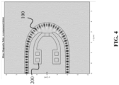
- FIG. 4 shows a top-view of a thermo-optic phase shifter 200 for regulating a temperature of a waveguide core 100 that is configured to excite a WGM according to an embodiment of this disclosure.
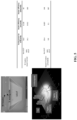
- FIG. 5 shows an energy efficiency comparison of a conventional Tungsten (W) heater and a WGM-based heater according to an embodiment of the disclosure.
- the WGM-based heater may be a thermo-optic phase shifter 200 or may be comprised in a thermo-optic phase shifter 200.
Landscapes
- Physics & Mathematics (AREA)
- General Physics & Mathematics (AREA)
- Optics & Photonics (AREA)
- Nonlinear Science (AREA)
- Engineering & Computer Science (AREA)
- Microelectronics & Electronic Packaging (AREA)
- Optical Integrated Circuits (AREA)
Abstract
Description
- The present disclosure relates to waveguides. The disclosure proposes a waveguide core. The waveguide core is bent according to a smooth curve or a family of smooth curves.
- When light propagates in a bent waveguide core, the center of the optical modes of the light may be shifted towards a waveguide core's outer boundary due to the bending. Generally, the smaller the bending curvature of the waveguide core is, the larger the shift of the optical mode center is. The shift may result in mode transition loss when connecting two waveguide cores with different curvatures. Or, for example, if a waveguide core comprises a connection between a straight waveguide core segment and a bent waveguide core segment, i.e., comprises a straight-bent waveguide core transition. To reduce the mode transition loss, conventional bent waveguide cores may be bent according to an Euler curve (see
FIG. 3 ), but better solutions are still needed. - In view of the above, an objective of this disclosure is to reduce loss in a waveguide core that includes at least one bent waveguide core segment. In particular, an objective is to reduce a loss caused by connections of different segments of the waveguide core, for example, segments of different curvature. Another objective is to improve the energy efficiency of thermo-optic phase shifters applied to such waveguide cores.
- These and other objectives are achieved by this disclosure, as described in the independent claims. Advantageous implementations are further described in the dependent claims.
- A first aspect of this disclosure provides a waveguide core having a smooth curve as an edge and/or centerline of the waveguide core, wherein a curvature of the smooth curve is continuous and the first order derivative of the curvature of the smooth curve with respect to an arc length of the smooth curve, for example, an entire arc length of the smooth curve, is continuous; wherein the smooth curve comprises a curve start point and a curve end point; wherein the derivative of the curvature of the smooth curve is zero at the curve start point and at the curve end point; wherein the curvature of the smooth curve is zero at the curve start point, and is non-zero or zero at the curve end point.
- The bent waveguide core of the first aspect allows reducing loss in the waveguide core, in particular, if the waveguide core has segments of different curvature and/or has also straight segments. For example, the waveguide core may be configured to minimize the mode transition loss.
- The curvature of the smooth curve may be not always zero.
- The curvature κ of the smooth curve may be defined by the transition of the tangential angle θ of the smooth curve, for example, along the arc length of the smooth curve, for example, along the entire arc length of the smooth curve. The curvature of the smooth curve may have a continuous transition of the tangential angle.
- The tangential angle difference between the curve start point and the curve end point may be less than π.
- The waveguide core may further have one or more other smooth curves as one or more other edges of the waveguide core.
- The waveguide core may further have one or more other smooth curves as one or more baseline curves. Each baseline curve may be parallel to an edge of the waveguide core and/or to a smooth curve associated with said edge, for example, along an arc length of a curve segment of the smooth curve or along an entire arc length of the smooth curve.
- In an implementation form of the first aspect, the smooth curve comprises a curve segment, wherein the curve segment comprises a start point of the curve segment and an end point of the curve segment; wherein the derivative of the curvature of the smooth curve is zero at the start point of the curve segment and is zero at the end point of the curve segment; and wherein the curvature of the smooth curve is zero at the start point of the curve segment and is non-zero at the end point of the curve segment.
- Thus, for example, the loss in the waveguide core at one or more connection points between one or more segments comprised in the smooth curve and/or between other waveguide cores connectable to the waveguide core may be reduced. This may be achieved, because the first order derivative of the curvature of the smooth curve with respect to the arc length of the smooth curve is continuous.
- The curvature of the smooth curve in the curve segment may be according to and/or may be defined by a third order, or larger order, polynomial function.
- The end point of the curve segment may be the curve end point. Alternatively, the start point of the curve segment may be the curve start point. Alternatively, the end point of the curve segment may not be the curve end point, and the start point of the curve segment may not be the curve start point.
- In a further implementation form of the first aspect, a Cartesian coordinate system is defined with the start point of the curve segment as its origin; wherein the x-axis and y-axis are defined to have the end point of the curve segment in the first quadrant, and a tangential angle of zero radian at the start point of the curve segment; wherein the tangential angle, for example in the unit of radian, of any point P on the curve segment is

- In a further implementation form of the first aspect, the curve segment of the smooth curve is parallel to a baseline curve; wherein the baseline curve comprises a start point of the baseline curve and an end point of the baseline curve; wherein a Cartesian coordinate system is defined with the start point of the baseline curve as its origin; wherein the x-axis and y-axis are defined to have the end point of the baseline curve in the first quadrant, and a tangential angle of zero radian at the start point of the baseline curve; wherein the tangential angle, for example in the unit of radian, of any point P on the baseline curve is

- In a further implementation form of the first aspect, the smooth curve further comprises a straight segment, wherein the straight segment comprises a start point of the straight segment and an end point of the straight segment; wherein the end point of the straight segment is connected to the start point of the curve segment.
- The start point of the straight segment may be the curve start point.
- In a further implementation form of the first aspect, the smooth curve further comprises a circular segment, wherein a curvature of the circular segment is constant; wherein the curvature of the circular segment is equal to the curvature of the smooth curve at the end point of the curve segment; wherein the circular segment comprises a start point of the circular segment and an end point of the circular segment; and wherein the end point of the curve segment is connected to the start point of the circular segment.
- The end point of the circular segment may be or may not be the curve end point.
- In a further implementation form of the first aspect, the curve segment is a first curve segment and wherein the smooth curve further comprises a second curve segment according to the first curve segment, wherein the curvature at the end point of the first curve segment is the same as the curvature at the end point of the second curve segment; and wherein the end point of the first curve segment is connected to the end point of the second curve segment, or wherein the end point of the circular segment is connected to the end point of the second curve segment.
- The curvature of the smooth curve in the second curve segment may be according to and/or defined by a third order or larger order polynomial function. Said function may or may not be the same function that may define the curvature of the smooth curve in the first curve segment.
- The second curve segment may be mirrored to the first curve segment.
- The second curve segment may be line symmetric to the first curve segment regarding a perpendicular bisector of the smooth curve along its arc length between the second curve segment and the first curve segment.
- The end point of the second curve segment may be or may not be the curve end point.
- The straight segment may be a first straight segment.
- The smooth curve may further comprise a second straight segment. The second straight segment may comprise a start point of the second straight segment and an end point of the second straight segment, wherein the start point of the second straight segment may be connected to the end point of the second curve segment. The end point of the second straight segment may be the curve end point.
- In a further implementation form of the first aspect, the waveguide core has a first smooth curve as an inner edge and/or centerline of the waveguide core, and has a second smooth curve as an outer edge of the waveguide core.
- The first smooth curve may be a smooth curve according to the first aspect or the implementation forms of the first aspect. The second smooth curve may be a smooth curve according to the first aspect or the implementation forms of the first aspect.
- A curvature of the waveguide core may define an inner edge of the waveguide core, and the curvature of the waveguide core may also define an outer edge of the waveguide core. For example, the inner edge of the waveguide core may be shorter due to a curvature of the waveguide core, and the outer edge of the waveguide core may be longer due the curvature of the waveguide core. The curvature of the waveguide core may refer to how the waveguide core is bent.
- For example, the inner edge may be an edge that follows a shortest path, along the longitudinal extension of the waveguide core, from a start cross section of the waveguide core to an end cross section of the waveguide core. The outer edge may be an edge that follows a longest path, along the longitudinal extension of the waveguide core, from the start cross section of the waveguide core to the end cross section of the waveguide core.
- The waveguide core may further have one or more other smooth curves as one or more other edges of the waveguide core.
- For example, the waveguide core may be a core of a slot waveguide or a core of a rib waveguide. The first edge, the second edge, and the one or more other edges may be defined along the longitudinal extension of the waveguide core and/or may define the waveguide core.
- In general, all edges of the waveguide core may refer to edges along the longitudinal extension of the waveguide core.
- In a further implementation form of the first aspect, the first smooth curve and the second smooth curve are parallel to each other.
- The first smooth curve may be parallel to the second smooth curve along the longitudinal extension of the waveguide core, for example, along the entire longitudinal extension of the waveguide core. Thus, the waveguide core may have a same width along the longitudinal extension, for example length, of the waveguide core.
- The constant width along the longitudinal extension of the waveguide core may be adjusted such that the waveguide core has optimized properties, for example low loss.
- In a further implementation form of the first aspect, the first smooth curve and the second smooth curve are not parallel to each other.
- The first smooth curve may be nonparallel to the second smooth curve along the longitudinal extension of the waveguide core. Thus, the waveguide core may have a varying width along the longitudinal extension, for example length, of the waveguide core.
- The varying width along the longitudinal extension of the waveguide core may be adjusted such that the waveguide core has optimized properties, for example low loss and/or excites a whispering gallery mode (WGM).
- In a further implementation form of the first aspect, the waveguide core is configured to be thermally connectable to a thermo-optic phase shifter in at least a portion of the inner boundary of the waveguide core.
- Alternatively or additionally, the waveguide core is configured to be electrically connectable to a thermo-optic phase shifter in at least the portion of the inner boundary of the waveguide core.
- The term "thermally connectable" may refer to being directly thermally connected or connectable. Two components being "thermally connectable" may include that said components may be in direct physically contact and/or attached to each other. For example, said components may be directly adjacent to each other. The term "thermally connectable" may not include only being connected by gas molecules and/or radiation. The term "thermally connectable" may refer to two solid components that may be in direct physical contact with each other, wherein said contact allows for direct heat transfer. For example, electrical wires can be connected to deliver current through for heating generation. The electrical wires can be metal, such as Cu, and Al etc., or doped semiconductor, such as Si, and Ge etc.
- The portion of the inner boundary of the waveguide core may be in, and/or may be associated with, and/or may correspond to, a portion of the circular segment of the smooth curve.
- Additionally or alternatively, the portion of the inner boundary of the waveguide core may be in, associated with, and/or correspond to a portion of the first curve segment and/or the second curve segment of the smooth curve, for example, if the smooth curve does not comprise a circular section or if the circular section is too small for thermally connecting the thermo-optic phase shifter to the waveguide core.
- The thermo-optic phase shifter may comprise a heater, wherein the heater may be thermally connectable to the waveguide core in at least the portion of the inner boundary of the waveguide core.
- In a further implementation form of the first aspect, a sidewall of the waveguide core facing towards the thermo-optic phase shifter in the at least portion of the inner boundary is configured to be open for the thermo-optic phase shifter.
- For example, a side wall of the waveguide core may be open and/or removed in a portion of the waveguide core.
- Thus, the thermo-optic phase shifter may be applied more efficiently to the waveguide core.
- The at least portion of the inner boundary may be configured to be open for the thermo-optic phase shifter, as the waveguide core is configured to excite a WGM. Thus, the waveguide core can be partially opened without increasing the loss of the waveguide core.
- In a further implementation form of the first aspect, a centerline of the waveguide core along the longitudinal extension of the waveguide core, for example, along an entire longitudinal extension of the waveguide core, defines a plane, and wherein the inner edge of the waveguide core and the outer edge of the waveguide core are in said plane along the longitudinal extension of the waveguide core.
- In a further implementation form of the first aspect, the waveguide core is configured to excite a whispering gallery mode.
- Thus, the energy efficiency of the thermo-optic phase shifter applied to the waveguide core can be increased.
- The waveguide core may be configured to primarily excite a WGM and secondly minimize the loss of the waveguide core.
- The waveguide core may have a minimized loss, for example, transition loss, based on configuring the edges and/or centerline of the waveguide core and/or the smooth curves associated with said edges and/or centerline.
- Further, in this disclosure the phrases "after" and "before" when referring to the smooth curve may correspond to a direction from the curve start point to the curve end point. Thus, the curve start point is positioned before the curve end point and the curve end point is positioned after the curve start point.
- Further, in this disclosure a top view may refer to a top view or a bottom view of a plane comprising the longitudinal extension direction of the waveguide core. The plane may be defined by and/or comprise the inner edge and the outer edge of the waveguide core. The top view and the bottom view of the plane may be mirrored.
- The above described aspects and implementation forms will be explained in the following description of specific embodiments in relation to the enclosed drawings, in which
- FIG. 1
- shows an exemplary waveguide core according to an embodiment of this disclosure.
- FIG. 2a
- shows a smooth curve according to an embodiment of this disclosure and a curve with a conventional circular bend.
- FIG. 2b
- shows respective smooth curves for different θc values for waveguide cores according to an embodiment of this disclosure.
- FIG. 2c
- shows a waveguide core having constant width according to an embodiment of this disclosure.
- FIG. 2d
- shows a waveguide core according to an embodiment of this disclosure having a varying width along its longitudinal extension.
- FIG. 3a
- shows two waveguide cores with constant width according to an embodiment of this disclosure and two conventional waveguide cores with constant width.
- FIG. 3b
- shows a conventional waveguide core with varying width and a waveguide core with varying width according to an embodiment of this disclosure.
- FIG. 3c
- shows a respective measured insertion loss for exemplary waveguide cores with constant width according to an embodiment of this disclosure.
- FIG. 3d
- shows a respective measured insertion loss for exemplary waveguide cores with varying width according to an embodiment of this disclosure.
- FIG. 4
- shows a top-view of a thermo-optic phase shifter for regulating a temperature of a waveguide core that is configured to excite a WGM according to an embodiment of this disclosure.
- FIG. 5
- shows an energy efficiency comparison of a conventional Tungsten (W) heater and a WGM-based heater according to an embodiment of the disclosure.
-
FIG. 1 shows anexemplary waveguide core 100 according to an embodiment of this disclosure. Thewaveguide core 100 has asmooth curve 101 as an edge and/or centerline of the waveguide core 100 (here an exemplarysmooth curve 101 is illustrated). For example, thewaveguide core 100 may have a respectivesmooth curve 101 as its one or more edges and/or a centerline. The respective edge and/or centerline of thewaveguide core 100 may be associated with, may correspond to, and/or may define saidsmooth curve 101. The smooth curve comprises acurve start point 102 and acurve end point 103. - In general, a curvature of the
smooth curve 101 is continuous, and the first order derivative of the curvature of thesmooth curve 101 with respect to an arc length of thesmooth curve 101 is continuous. The derivative of the curvature of thesmooth curve 101 is zero at thecurve start point 102 and at thecurve end point 103. The curvature of thesmooth curve 101 is zero at thecurve start point 102, and is non-zero or zero at thecurve end point 103. - The
exemplary waveguide core 100 shown inFIG. 1 has asmooth curve 101 as a centerline. For example, the distance from the centerline of thewaveguide core 100 to respectively an inner edge and an outer edge of thewaveguide core 100 may be W/2 (as indicated inFIG. 1 ), wherein W may be a width of thewaveguide core 100. In this example, the inner and outer edges and the centerlinesmooth curve 101 have the same curvature, because the waveguide core width is constant along the longitudinal extension of thewaveguide core 100. - Further,
FIG. 1 shows that thewaveguide core 100 may also have twostraight segments straight segment 107 may be positioned before thecurve start point 102, and the otherstraight segment 108 may be positioned after thecurve end point 103. In this example, the twostraight segments smooth curve 101. Alternatively, however, the exemplarystraight segments FIG. 1 could be comprised in thesmooth curve 101. In this case, thecurve start point 102 and thecurve end point 103 would be at a different position than shown onFIG. 1 . The curve startpoint 102 would be at a start point of one of thestraight segments 107, and thecurve end point 103 would be at an end point the otherstraight segment 108. - The
waveguide core 100 may be connectable to and/or comprised in a waveguide. Thewaveguide core 100 may be connectable to, comprised in, surrounded by, and/or covered by a cladding. A waveguide may comprise thewaveguide core 100 and a cladding surrounding thewaveguide core 100. -
FIGs. 2a to 2d show exemplarysmooth curves 101 forwaveguide cores 100 according to embodiments of this disclosure. Anywaveguide core 100 according to this disclosure may be used to replace a conventional circular bend for connecting arbitrarily two straight waveguides (WG1 and WG2). -
FIG. 2a shows asmooth curve 101 for awaveguide core 100 according to an embodiment of this disclosure, and a conventional curve with a circular bend. The conventional curve is shown with a dashed line. -
FIG. 2b shows respectivesmooth curves 101 for different θc values forwaveguide cores 100 according to an embodiment of this disclosure. Eachsmooth curve 101 shown inFIG. 2b may be defined by a θc value. By adjusting the θc value, thesmooth curve 101 and accordingly thewaveguide core 100 may be adjusted. -
FIG. 2c shows awaveguide core 100 having constant width according to an embodiment of this disclosure. Thiswaveguide core 100 may have asmooth curve 100 as a centerline of thewaveguide core 100. The width of thewaveguide core 100 may be W (as indicated inFIG. 2c ). Thewaveguide core 100 may be surrounded by a cladding (not shown). -
FIG. 2d shows awaveguide core 100 according to an embodiment of this disclosure having a varying width along its longitudinal extension. Thewaveguide core 100 shown inFIG. 2d has a firstsmooth curve 101a and a secondsmooth curve 101b. The twosmooth curves waveguide core 100. Further,FIG. 2d shows a thirdsmooth curve 101c and a fourthsmooth curve 101d which are inside thewaveguide core 100. The thirdsmooth curve 101c may be a first baseline curve, and the fourthsmooth curve 101d may be a second baseline curve. In particular, the thirdsmooth curve 101c may correspond to the curvature of the inner edge of thewaveguide core 100 and/or the firstsmooth curve 101a, and the fourthsmooth curve 101d may correspond to the curvature of the outer edge of thewaveguide core 100 and/or the second smooth curve. The inner edge and the outer edge may be defined with regards to the direction in which thewaveguide core 100 is bent. Again, thewaveguide core 100 may be surrounded by a cladding (not shown). The cladding may have the same thickness along the length of thewaveguide core 100, for example, along the entire length of thewaveguide core 100. - The third
smooth curve 101c may run parallel to the inner edge of thewaveguide core 100, for example, along the arc length of thefirst curve segment 104, and the fourthsmooth curve 101b may run parallel to the outer edge of thewaveguide core 100, for example, along the arc length of thefirst curve segment 104. For example, the thirdsmooth curve 101c and the fourthsmooth curve 101d may be offset respectively from the inner edge and the outer edge, for instance, with a distance of 3W/4 and W/4, or any other number or pair of numbers. - In an example, the
smooth curve 101 of anywaveguide core 100 of this disclosure may comprise, along the arc length of thesmooth curve 101, the following in sequence: a firststraight segment 107, afirst curve segment 104, acircular segment 105, asecond curve segment 106, and a secondstraight segment 108. - In another example, the
smooth curve 101 of anywaveguide core 100 of this disclosure may comprise, along the arc length of thesmooth curve 101, in sequence a firststraight segment 107, afirst curve segment 104, asecond curve segment 106, and a secondstraight segment 108. Thus, thesmooth curve 101 may have zero curvature at the curve start point and the curve end point and the derivative of the curvature of thesmooth curve 101 may in said points may be zero. - In another example, the
smooth curve 101 of anywaveguide core 100 of this disclosure may comprise, along the arc length of thesmooth curve 101, in sequence a firststraight segment 107 and afirst curve segment 104. Thus, thesmooth curve 101 may have zero curvature at the curve start point and non-zero curvature at the curve end point, and the derivative of the curvature of thesmooth curve 101 in said points may be zero. - For the following part of the description, a coordinate system is defined based on WG1.
FIG. 2a , shows the center of the WG1 end is the origin of the coordinate system, and the direction of WG1 is the x-axis direction. (x 1,y 1) = (0, 0) and (x 2 ,y 2) = (Reff sin θt , Reff (1 - cos θt )) are the two given points that can be connected by asmooth curve 101. Further, for the following part of the description, only y 2 > 0 is considered. Alternatively, for the case of y 2 < 0, the bend design can be done by first connecting to (x 2 , -y 2) with the procedure described below, and then mirroring the generated bend with respect to x-axis to connect to (x 2 , y 2). - Each
smooth curve 101 may comprise a bend. The bend may define an entire curvature and/or an entire curved section of thesmooth curve 101. For example, all curved parts of the smooth curve may be comprised and/or defined by the bend of the smooth curve. The smooth curve may further comprise or not comprise one or morestraight segments - In general, the bend of each
smooth curve 101 shown inFIG. 2 may comprise three segments, labelled asPoly3 104,Circ 105, and Poly3' 106.Circ 105 is acircular segment 105 with the curvature angle of θc , wherein θc may be limited by 0 ≤ θc ≤ θt. When θc = 0, the bend consists ofPoly3 104 and Poly3' 106 segments only and nocircular segment 105. When θc = θt, the bend is the normal circular bend with a radius Reff. - The curvature of the
smooth curve 101 may be the first order derivative of the tangential angle along the arc length of the smooth curve. - The steps to generate a
smooth curve 101 and/or awaveguide core 100, for example, a low lossbend waveguide core 100, may comprise: - Step-1: select the 3rd polynomial function as a base curvature function for Poly3:

smooth curve 101. θ can be expressed as:
- Step-2: Set the boundary conditions for the Poly3 segment 104:
θ is continuous. Similarly, a conventional circular bend would be continuous. Additionally, the κ transits gradually (i.e. κ is continuous) and smoothly (i.e. κ' = dκ/ds is continuous) at both connection points to the straight waveguides WG1 and WG2.
Poly3 segment 104, which is determined in Step-3. The continuity of κ at s = L is not included in this equation, which will be applied in Step-5.
Taking Eq. (3) as the boundary conditions for Eq. (1) and Eq. (2), the curvature κ and the tangential angle θ can be expressed as:


- Step-3: Calculate L:
The osculating circle center (xo, yo ) at the end point of thePoly3 segment 104 can be expressed as the function of total length L of thePoly3 segment 104.
Poly3 segment 104 to the middlecircular segment 105 Circ, (xo, yo ) should be on the bisector of the bend angle θt. i.e. L is the solution of the following equation:
- Step-4: Generate the coordinates on the Poly3 segment 104:
The coordinates on the Poly3 segment (x,y) can be generated by Eq. (7) where 0 ≤ l ≤ L.
- Step-5: Generate the coordinates on the Circ segment 105:
The curvature of theCirc segment 105 may be chosen to be
Poly3 segment 104 and theCirc segment 105. TheCirc segment 105 may be circular with the radius of
- Step-6: Generate the coordinates on the Poly3' segment 106:
The low-loss bend may be symmetric with respect to the bisector of the bend angle θt. The Poly3'segment 106 may be generated by mirroring thePoly3 segment 104 with respect to the bisector of the bend angle θt. - Step-7: Generate the waveguide core 100:
Given the value of θc, thesmooth curve 101 connecting (0, 0) and (Reff sin θt , Reff (1-cos θt )) can be generated with Step-1 to Step-6. The generatedsmooth curve 101 may be controlled and/or adjusted by θc (0 ≤ θc ≤ θt ). The smaller the θc is, the more the middle of the curve is shifted to the inner side of the bending (seeFIG. 2b ). - Step-1 to Step-6 may be used to generate the coordinates of a
waveguide baseline curve waveguide core 100 may be generated as a parallel curve to thebaseline curve - To generate a bent waveguide core with constant width of W, the inner and outer waveguide core edges or boundaries may be generated as a parallel curve with a distance of

FIG. 2c ). - To generate a
bent waveguide core 100 with varying width, two waveguide baseline curves 101c, 101d may be generated with different θc values which are used to generate the inner and outer edges respectively. For example, the inner and outer waveguide core edges or boundaries may be generated as a parallel curve with a distance of
FIG. 2d ). - A low-loss
bent waveguide core 100 may improve conventional integrated photonic systems. Embodiments of this disclosure provide a low-lossbent waveguide core 100, wherein the bending curvature changes gradually and smoothly. Awaveguide core 100 bend, for example a poly3-circular bend, may be constructed with one adjustable parameter θc which can be used to lower the loss, for example, when a waveguide sidewall roughness exists. - A curvature of a
waveguide core 100 may transit gradually such that the transition loss is lowered. Awaveguide core 100 according to an embodiment of this disclosure may have a waveguide core curvature κ transit not only gradually (i.e. κ is continuous) but also smoothly (i.e. κ' is continuous). Conventional designs do not have a continuous κ' during a straight-bent waveguide transition. The continuous κ' may result in lower transition loss as shown inFIG. 3a and 3c . - The coordinates of a straight-
bent transition curve 101 may be determined by the base curvature function and the boundary conditions. - i) The boundary conditions of the
waveguide core 100 may be configured such that the curvature derivative κ' is continuous at straight-bent waveguide core connection points. - ii) The
waveguide core 100 may comprise an optionalcircular segment 105 at the middle of bent waveguide which can reduce the bending loss (seeFIG. 2a and 2c ). - iii) The
waveguide core 100 may be configured to excite a WGM by giving the bend inner and outer edges differentcircular segment 105 angle θc (seeFIG. 2b and 2d ). - Combining the transition curve design with
waveguide core 100 widening during the transition can further reduce the loss. - The
waveguide core 100 may have only one adjustable parameter. Thus, saidwaveguide core 100 may be easy to use in practical applications. - The
waveguide core 100 may have lower loss thanconventional waveguide cores 100, as the curve associated with thewaveguide core 100 is smoother. - A
waveguide core 100 according to this disclosure may be associated with a bend with arbitrary angle θc and/or the loss may be lower because the mode transition loss may be reduced. -
FIGs. 3a to 3d shows multipleexemplary waveguide cores 100. -
FIG. 3a shows twowaveguide cores 100 with constant width according to an embodiment of this disclosure and two conventional waveguide cores with constant width. -
FIG. 3b shows a conventional waveguide core with varying width and awaveguide core 100 with varying width according to an embodiment of this disclosure. -
FIG. 3c shows a respective measured insertion loss forexemplary waveguide cores 100 with constant width according to an embodiment of this disclosure. -
FIG. 3d shows a respective measured insertion loss forexemplary waveguide cores 100 with varying width according to an embodiment of this disclosure. - A varying width of the waveguide core 100 Wmax may be achieved by varying the parameter θc for the inner edge or boundary while fixing the parameter θc for the outer edge or boundary. Alternatively, the θc for the inner boundary and the θc for the outer boundary may be varied. The waveguide may be fabricated on a SiN with Silicon oxide as the bottom and upper cladding. The thickness of SiN may be 150 nm, the width in WG1 and WG2 may be 0.5 µm, and the light wavelength may be 638 nm.
- Conventionally,
waveguide cores 100 associated with oval-circular curves may be used to widen the waveguide to excite a WGM. For example, a circular curve as the outer boundary of the bend, and an oval curve as the inner boundary of the bend may be used. However, the usage of such conventionally waveguidecores 100 is limited to a maximal 180° bend, and have a straight-bent transition loss. - The
waveguide core 100 and/or the bend of thewaveguide core 100 may excite a WGM adiabatically, for example, by giving the inner and outer boundary of thewaveguide core 100 different θc values. If a WGM is excited in thewaveguide core 100, a heater, for example, a doped silicon heater, can be embedded into the bend of thewaveguide core 100 which can significantly improve the energy efficiency of a thermo-optic phase shifter comprising the heater. For conventional thermo-optic phase shifters, the heater may be placed on top of the waveguide. - Doped Si may be used as a heater to improve the energy efficiency. This may be more efficient because Si has, for example, more than 100x higher thermal conductivity than SiO2. When the heating is generated in the waveguide, most of the heating may propagate along the longitudinal extension of the waveguide core. A
waveguide core 100 according to an embodiment of this disclosure may enable and/or be connectable to a whispering gallery mode-based (WGM-based) doped Si heater. -
FIG. 4 shows a top-view of a thermo-optic phase shifter 200 for regulating a temperature of awaveguide core 100 that is configured to excite a WGM according to an embodiment of this disclosure. -
FIG. 5 shows an energy efficiency comparison of a conventional Tungsten (W) heater and a WGM-based heater according to an embodiment of the disclosure. - The WGM-based heater may be a thermo-
optic phase shifter 200 or may be comprised in a thermo-optic phase shifter 200. - The disclosure has been described in conjunction with various embodiments as examples as well as implementations. However, other variations can be understood and effected by those persons skilled in the art and practicing the claimed matter, from the studies of the drawings, this disclosure and the independent claims. In the claims as well as in the description the word "comprising" does not exclude other elements or steps and the indefinite article "a" or "an" does not exclude a plurality. A single element or other unit may fulfill the functions of several entities or items recited in the claims. The mere fact that certain measures are recited in the mutual different dependent claims does not indicate that a combination of these measures cannot be used in an advantageous implementation.
Claims (14)
- A waveguide core (100) having a smooth curve (101) as an edge and/or centerline of the waveguide core (100),wherein a curvature of the smooth curve (101) is continuous and the first order derivative of the curvature of the smooth curve (101) with respect to an arc length of the smooth curve (101) is continuous;wherein the smooth curve (101) comprises a curve start point (102) and a curve end point (103);wherein the derivative of the curvature of the smooth curve (101) is zero at the curve start point (102) and at the curve end point (103);wherein the curvature of the smooth curve (101) is zero at the curve start point (102), and is non-zero or zero at the curve end point (103).
- The waveguide core (100) according to claim 1, wherein the smooth curve (101) comprises a curve segment (104),wherein the curve segment (104) comprises a start point of the curve segment (104) and an end point of the curve segment (104);wherein the derivative of the curvature of the smooth curve (101) is zero at the start point of the curve segment (104) and is zero at the end point of the curve segment (104); andwherein the curvature of the smooth curve (101) is zero at the start point of the curve segment (104) and is non-zero at the end point of the curve segment (104).
- The waveguide core (100) according to claim 2,wherein a Cartesian coordinate system is defined with the start point of the curve segment (104) as its origin;wherein the x-axis and y-axis are defined to have the end point of the curve segment (104) in the first quadrant, and a tangential angle of zero radian at the start point of the curve segment (104);wherein the tangential angle of any point P on the curve segment (104) is
 wherein s is the length of the arc length of the smooth curve (101) from the start point of the curve segment (104) to a point P;wherein κe is the curvature at the end point of the curve segment (104), and θe is the tangential angle at the end point of the curve segment (104).
 - The waveguide core (100) according to claim 2, wherein the curve segment (104) of the smooth curve (101) is parallel to a baseline curve;wherein the baseline curve comprises a start point of the baseline curve and an end point of the baseline curve;wherein a Cartesian coordinate system is defined with the start point of the baseline curve as its origin;wherein the x-axis and y-axis are defined to have the end point of the baseline curve in the first quadrant, and a tangential angle of zero radian at the start point of the baseline curve;wherein the tangential angle of any point P on the baseline curve is
 wherein s is the length of the arc length of the smooth curve (101) from the start point of the baseline curve to a point P;wherein κe is the curvature at the end point of the baseline curve, and θe is the tangential angle at the end point of the baseline curve.
 - The waveguide core (100) according to one of the claims 2 to 4, wherein the smooth curve (101) further comprises a straight segment (107),wherein the straight segment (107) comprises a start point of the straight segment (107) and an end point of the straight segment (107);wherein the end point of the straight segment (107) is connected to the start point of the curve segment (104).
- The waveguide core (100) according to one of the claims 2 to 5, wherein the smooth curve (101) further comprises a circular segment (105),wherein a curvature of the circular segment (105) is constant;wherein the curvature of the circular segment (105) is equal to the curvature of the smooth curve (101) at the end point of the curve segment (104);wherein the circular segment (105) comprises a start point of the circular segment (105) and an end point of the circular segment (105); andwherein the end point of the curve segment (104) is connected to the start point of the circular segment (105).
- The waveguide core (100) according to one of the claims 2 to 6, wherein the curve segment (104) is a first curve segment (104) and wherein the smooth curve (101) further comprises a second curve segment (106) according to the first curve segment (104),wherein the curvature at the end point of the first curve segment (104) is the same as the curvature at the end point of the second curve segment (104); andwherein the end point of the first curve segment (104) is connected to the end point of the second curve segment (104), or wherein the end point of the circular segment (105) is connected to the end point of the second curve segment (104).
- The waveguide core (100) according to any of the preceding claims, the waveguide core (100) having a first smooth curve (101a) as an inner edge and/or centerline of the waveguide core (100), and having a second smooth curve (101b) as an outer edge of the waveguide core (100).
- The waveguide core (100) according to claim 8, wherein the first smooth curve (101a) and the second smooth curve (101b) are parallel to each other.
- The waveguide core (100) according to claim 8,
wherein the first smooth curve (101a) and the second smooth curve (101b) are not parallel to each other. - The waveguide core (100) according to one of the claims 8 to 10,
wherein the waveguide core (100) is configured to be thermally connectable to a thermo-optic phase shifter (200) in at least a portion of the inner boundary of the waveguide core (100). - The waveguide core (100) according to claim 11,
wherein a sidewall of the waveguide core (100) facing towards the thermo-optic phase shifter (200) in the at least portion of the inner boundary is configured to be open for the thermo-optic phase shifter (200). - The waveguide core (100) according to one of the claims 8 to 12,wherein a centerline of the waveguide core (100) along the longitudinal extension of the waveguide core (100) defines a plane, andwherein the inner edge of the waveguide core (100) and the outer edge of the waveguide core (100) are in said plane along the longitudinal extension of the waveguide core (100).
- The waveguide core (100) according to any of the preceding claims,
wherein the waveguide core (100) is configured to excite a whispering gallery mode.
Priority Applications (3)
| Application Number | Priority Date | Filing Date | Title |
|---|---|---|---|
| EP22214181.4A EP4386456B1 (en) | 2022-12-16 | 2022-12-16 | A low-loss optical bent waveguide core |
| CN202311657109.8A CN118210104A (en) | 2022-12-16 | 2023-12-05 | Low-loss light-bending waveguide core |
| US18/541,931 US20240201440A1 (en) | 2022-12-16 | 2023-12-15 | Low-loss optical bent waveguide core |
Applications Claiming Priority (1)
| Application Number | Priority Date | Filing Date | Title |
|---|---|---|---|
| EP22214181.4A EP4386456B1 (en) | 2022-12-16 | 2022-12-16 | A low-loss optical bent waveguide core |
Publications (2)
| Publication Number | Publication Date |
|---|---|
| EP4386456A1 true EP4386456A1 (en) | 2024-06-19 |
| EP4386456B1 EP4386456B1 (en) | 2026-03-04 |
Family
ID=84537626
Family Applications (1)
| Application Number | Title | Priority Date | Filing Date |
|---|---|---|---|
| EP22214181.4A Active EP4386456B1 (en) | 2022-12-16 | 2022-12-16 | A low-loss optical bent waveguide core |
Country Status (3)
| Country | Link |
|---|---|
| US (1) | US20240201440A1 (en) |
| EP (1) | EP4386456B1 (en) |
| CN (1) | CN118210104A (en) |
Families Citing this family (1)
| Publication number | Priority date | Publication date | Assignee | Title |
|---|---|---|---|---|
| CN122307827A (en) * | 2026-06-03 | 2026-06-30 | 上海羲禾科技股份有限公司 | Bending waveguides and related equipment |
Citations (3)
| Publication number | Priority date | Publication date | Assignee | Title |
|---|---|---|---|---|
| US5524165A (en) * | 1994-01-19 | 1996-06-04 | Commissariat A L'energie Atomique | Method for optimizing a path length of an optical guide and optical guide obtained by said method |
| US20040208465A1 (en) * | 2003-04-18 | 2004-10-21 | Yury Logvin | Planar waveguide structure with tightly curved waveguides |
| US20210294032A1 (en) * | 2020-08-26 | 2021-09-23 | Chongqing Institute Of East China Normal University | Silicon nitride phased array chip based on a suspended waveguide structure |
Family Cites Families (18)
| Publication number | Priority date | Publication date | Assignee | Title |
|---|---|---|---|---|
| US5940548A (en) * | 1996-07-10 | 1999-08-17 | Nippon Telegraph And Telephone Corporation | Guided-wave circuit with optical characteristics adjusting plate, method for producing it, and apparatus for producing optical characteristics adjusting plate |
| JP2002202419A (en) * | 2000-12-28 | 2002-07-19 | Furukawa Electric Co Ltd:The | Array waveguide diffraction grating type optical multiplexer / demultiplexer and optical waveguide circuit |
| GB2376532A (en) * | 2001-06-15 | 2002-12-18 | Kymata Ltd | Thermally controlled optical resonator |
| GB2379517B (en) * | 2001-09-11 | 2003-08-13 | Kymata Netherlands B V | Optical arrayed waveguide grating |
| WO2004077117A1 (en) * | 2003-02-26 | 2004-09-10 | Fujitsu Limited | Array waveguide type wavelength multiplexing/demultiplexing device and optical transmission device |
| JP3721565B2 (en) * | 2004-02-27 | 2005-11-30 | 学校法人慶應義塾 | Optical functional waveguide, optical modulator, arrayed waveguide diffraction grating, and dispersion compensation circuit |
| JP4717765B2 (en) * | 2006-09-13 | 2011-07-06 | Nttエレクトロニクス株式会社 | Optical chip for arrayed waveguide diffraction grating type optical multiplexing / demultiplexing circuit, waveguide substrate, and method for manufacturing optical chip for arrayed waveguide grating optical multiplexing / demultiplexing circuit |
| US12135286B1 (en) * | 2006-12-06 | 2024-11-05 | Mohammad A. Mazed | Optical biomodule for detection of diseases at an early onset |
| US9823737B2 (en) * | 2008-04-07 | 2017-11-21 | Mohammad A Mazed | Augmented reality personal assistant apparatus |
| US10529003B2 (en) * | 2008-04-07 | 2020-01-07 | Mohammad A. Mazed | Optical biomodule for detection of diseases at an early onset |
| US7853108B2 (en) * | 2006-12-29 | 2010-12-14 | Massachusetts Institute Of Technology | Fabrication-tolerant waveguides and resonators |
| US8340484B2 (en) * | 2010-01-05 | 2012-12-25 | Board Of Regents, The University Of Texas System | Compact multi-port optical signal processor |
| US8582929B2 (en) * | 2010-10-15 | 2013-11-12 | Northwestern University | Ultra-sensitive electric field detection device |
| US9088371B2 (en) * | 2011-04-30 | 2015-07-21 | Rwth Aachen | WDM telecommunications link with coherent detection and optical frequency comb sources |
| WO2014043800A1 (en) * | 2012-09-24 | 2014-03-27 | Tornado Medical Systems Inc. | Wavenumber-linearized spectrometer on chip in a spectral-domain optical coherence tomography system |
| US10418238B2 (en) * | 2017-05-12 | 2019-09-17 | Ohio State Innovation Foundation | Devices, systems, and methods for light emission and detection using amorphous silicon |
| WO2019016603A1 (en) * | 2017-07-17 | 2019-01-24 | Rockley Photonics Limited | Athermalized multi-path interference filter |
| US12380059B2 (en) * | 2019-09-28 | 2025-08-05 | Mazed Mohammad A | Super system on chip |
-
2022
- 2022-12-16 EP EP22214181.4A patent/EP4386456B1/en active Active
-
2023
- 2023-12-05 CN CN202311657109.8A patent/CN118210104A/en active Pending
- 2023-12-15 US US18/541,931 patent/US20240201440A1/en active Pending
Patent Citations (3)
| Publication number | Priority date | Publication date | Assignee | Title |
|---|---|---|---|---|
| US5524165A (en) * | 1994-01-19 | 1996-06-04 | Commissariat A L'energie Atomique | Method for optimizing a path length of an optical guide and optical guide obtained by said method |
| US20040208465A1 (en) * | 2003-04-18 | 2004-10-21 | Yury Logvin | Planar waveguide structure with tightly curved waveguides |
| US20210294032A1 (en) * | 2020-08-26 | 2021-09-23 | Chongqing Institute Of East China Normal University | Silicon nitride phased array chip based on a suspended waveguide structure |
Also Published As
| Publication number | Publication date |
|---|---|
| US20240201440A1 (en) | 2024-06-20 |
| EP4386456B1 (en) | 2026-03-04 |
| CN118210104A (en) | 2024-06-18 |
Similar Documents
| Publication | Publication Date | Title |
|---|---|---|
| US20210373413A1 (en) | Optical Modulator From Standard Fabrication Processing | |
| US7184625B2 (en) | Optical waveguide grating coupler incorporating reflective optical elements and anti-reflection elements | |
| US20020076188A1 (en) | Optical waveguides with trench structures | |
| JP4127975B2 (en) | Optical waveguide device | |
| CN104781708A (en) | curved light guide | |
| EP1705515A2 (en) | Curved ridge optical waveguide, optical device, and method of manufacturing optical waveguide | |
| US20180275342A1 (en) | Optical waveguide, corresponding coupling arrangement, apparatus and method | |
| US20240201440A1 (en) | Low-loss optical bent waveguide core | |
| US20160341896A1 (en) | Methods and systems relating to optical waveguide tapers | |
| US10921518B2 (en) | Skewed adiabatic transition | |
| WO2004008207A1 (en) | Improved optical splitter with taperd multimode interference waveguide | |
| CN114265150B (en) | Compact coil optical waveguide supporting long-distance low-loss transmission on chip | |
| CN114442224B (en) | Edge coupler comprising a material with a tunable refractive index | |
| CN114488405A (en) | Design method of double-waveguide adiabatic mode coupler | |
| US9659591B1 (en) | Polynomial spiral waveguide that facilitates coupling light to a near-field transducer at an oblique angle | |
| JP2017161591A (en) | Refractive index control element, optical phase shifter, light switch and method for manufacturing refractive index control element | |
| CN113359238A (en) | Two-arm unequal-height asymmetric waveguide fiber end face coupler based on mode evolution | |
| JPH1164654A (en) | Optical waveguide | |
| CN115185037B (en) | A single-mode 90° curved waveguide based on a silicon-based platform and its production method | |
| JPH1054915A (en) | Optical branch element | |
| CN104035158A (en) | Optical waveguide chip with micro-optical gyroscope Sagnac effect and preparation method thereof | |
| WO2023065582A1 (en) | Thermo-optic phase shifter | |
| US20260003126A1 (en) | Optical coupler and fabrication method thereof | |
| CN118011560A (en) | A large delay line supporting on-chip multi-mode low-loss transmission | |
| CN118625446A (en) | Spot Size Converter |
Legal Events
| Date | Code | Title | Description |
|---|---|---|---|
| PUAI | Public reference made under article 153(3) epc to a published international application that has entered the european phase |
Free format text: ORIGINAL CODE: 0009012 |
|
| STAA | Information on the status of an ep patent application or granted ep patent |
Free format text: STATUS: THE APPLICATION HAS BEEN PUBLISHED |
|
| AK | Designated contracting states |
Kind code of ref document: A1 Designated state(s): AL AT BE BG CH CY CZ DE DK EE ES FI FR GB GR HR HU IE IS IT LI LT LU LV MC ME MK MT NL NO PL PT RO RS SE SI SK SM TR |
|
| STAA | Information on the status of an ep patent application or granted ep patent |
Free format text: STATUS: REQUEST FOR EXAMINATION WAS MADE |
|
| 17P | Request for examination filed |
Effective date: 20241212 |
|
| GRAP | Despatch of communication of intention to grant a patent |
Free format text: ORIGINAL CODE: EPIDOSNIGR1 |
|
| STAA | Information on the status of an ep patent application or granted ep patent |
Free format text: STATUS: GRANT OF PATENT IS INTENDED |
|
| INTG | Intention to grant announced |
Effective date: 20251029 |
|
| GRAS | Grant fee paid |
Free format text: ORIGINAL CODE: EPIDOSNIGR3 |
|
| GRAA | (expected) grant |
Free format text: ORIGINAL CODE: 0009210 |
|
| STAA | Information on the status of an ep patent application or granted ep patent |
Free format text: STATUS: THE PATENT HAS BEEN GRANTED |
|
| AK | Designated contracting states |
Kind code of ref document: B1 Designated state(s): AL AT BE BG CH CY CZ DE DK EE ES FI FR GB GR HR HU IE IS IT LI LT LU LV MC ME MK MT NL NO PL PT RO RS SE SI SK SM TR |
|
| REG | Reference to a national code |
Ref country code: CH Ref legal event code: F10 Free format text: ST27 STATUS EVENT CODE: U-0-0-F10-F00 (AS PROVIDED BY THE NATIONAL OFFICE) Effective date: 20260304 Ref country code: GB Ref legal event code: FG4D |
|
| P01 | Opt-out of the competence of the unified patent court (upc) registered |
Free format text: CASE NUMBER: UPC_APP_0004250_4386456/2026 Effective date: 20260205 |
|
| REG | Reference to a national code |
Ref country code: DE Ref legal event code: R096 Ref document number: 602022031546 Country of ref document: DE |
|
| REG | Reference to a national code |
Ref country code: IE Ref legal event code: FG4D |
|
| PG25 | Lapsed in a contracting state [announced via postgrant information from national office to epo] |
Ref country code: RS Free format text: LAPSE BECAUSE OF FAILURE TO SUBMIT A TRANSLATION OF THE DESCRIPTION OR TO PAY THE FEE WITHIN THE PRESCRIBED TIME-LIMIT Effective date: 20260604 |
|
| PG25 | Lapsed in a contracting state [announced via postgrant information from national office to epo] |
Ref country code: ES Free format text: LAPSE BECAUSE OF FAILURE TO SUBMIT A TRANSLATION OF THE DESCRIPTION OR TO PAY THE FEE WITHIN THE PRESCRIBED TIME-LIMIT Effective date: 20260304 |
|
| REG | Reference to a national code |
Ref country code: NL Ref legal event code: MP Effective date: 20260304 |
|
| PG25 | Lapsed in a contracting state [announced via postgrant information from national office to epo] |
Ref country code: PL Free format text: LAPSE BECAUSE OF FAILURE TO SUBMIT A TRANSLATION OF THE DESCRIPTION OR TO PAY THE FEE WITHIN THE PRESCRIBED TIME-LIMIT Effective date: 20260304 |
|
| PG25 | Lapsed in a contracting state [announced via postgrant information from national office to epo] |
Ref country code: GR Free format text: LAPSE BECAUSE OF FAILURE TO SUBMIT A TRANSLATION OF THE DESCRIPTION OR TO PAY THE FEE WITHIN THE PRESCRIBED TIME-LIMIT Effective date: 20260605 |
|
| REG | Reference to a national code |
Ref country code: LT Ref legal event code: MG9D |
|
| PG25 | Lapsed in a contracting state [announced via postgrant information from national office to epo] |
Ref country code: LT Free format text: LAPSE BECAUSE OF FAILURE TO SUBMIT A TRANSLATION OF THE DESCRIPTION OR TO PAY THE FEE WITHIN THE PRESCRIBED TIME-LIMIT Effective date: 20260304 |
|
| PG25 | Lapsed in a contracting state [announced via postgrant information from national office to epo] |
Ref country code: NO Free format text: LAPSE BECAUSE OF FAILURE TO SUBMIT A TRANSLATION OF THE DESCRIPTION OR TO PAY THE FEE WITHIN THE PRESCRIBED TIME-LIMIT Effective date: 20260604 |
|
| PG25 | Lapsed in a contracting state [announced via postgrant information from national office to epo] |
Ref country code: SE Free format text: LAPSE BECAUSE OF FAILURE TO SUBMIT A TRANSLATION OF THE DESCRIPTION OR TO PAY THE FEE WITHIN THE PRESCRIBED TIME-LIMIT Effective date: 20260304 Ref country code: FI Free format text: LAPSE BECAUSE OF FAILURE TO SUBMIT A TRANSLATION OF THE DESCRIPTION OR TO PAY THE FEE WITHIN THE PRESCRIBED TIME-LIMIT Effective date: 20260304 |
|
| PG25 | Lapsed in a contracting state [announced via postgrant information from national office to epo] |
Ref country code: HR Free format text: LAPSE BECAUSE OF FAILURE TO SUBMIT A TRANSLATION OF THE DESCRIPTION OR TO PAY THE FEE WITHIN THE PRESCRIBED TIME-LIMIT Effective date: 20260304 |
|
| PG25 | Lapsed in a contracting state [announced via postgrant information from national office to epo] |
Ref country code: LV Free format text: LAPSE BECAUSE OF FAILURE TO SUBMIT A TRANSLATION OF THE DESCRIPTION OR TO PAY THE FEE WITHIN THE PRESCRIBED TIME-LIMIT Effective date: 20260304 |
|
| PG25 | Lapsed in a contracting state [announced via postgrant information from national office to epo] |
Ref country code: BG Free format text: LAPSE BECAUSE OF FAILURE TO SUBMIT A TRANSLATION OF THE DESCRIPTION OR TO PAY THE FEE WITHIN THE PRESCRIBED TIME-LIMIT Effective date: 20260304 |