EP4386394A1 - Condition monitoring method of an electric conductor - Google Patents
Condition monitoring method of an electric conductor Download PDFInfo
- Publication number
- EP4386394A1 EP4386394A1 EP22383203.1A EP22383203A EP4386394A1 EP 4386394 A1 EP4386394 A1 EP 4386394A1 EP 22383203 A EP22383203 A EP 22383203A EP 4386394 A1 EP4386394 A1 EP 4386394A1
- Authority
- EP
- European Patent Office
- Prior art keywords
- conductor
- voltage signal
- cable
- characteristic admittance
- state parameter
- Prior art date
- Legal status (The legal status is an assumption and is not a legal conclusion. Google has not performed a legal analysis and makes no representation as to the accuracy of the status listed.)
- Granted
Links
Images

Classifications
-
- G—PHYSICS
- G01—MEASURING; TESTING
- G01R—MEASURING ELECTRIC VARIABLES; MEASURING MAGNETIC VARIABLES
- G01R31/00—Arrangements for testing electric properties; Arrangements for locating electric faults; Arrangements for electrical testing characterised by what is being tested not provided for elsewhere
- G01R31/08—Locating faults in cables, transmission lines, or networks
- G01R31/11—Locating faults in cables, transmission lines, or networks using pulse reflection methods
-
- G—PHYSICS
- G01—MEASURING; TESTING
- G01R—MEASURING ELECTRIC VARIABLES; MEASURING MAGNETIC VARIABLES
- G01R19/00—Arrangements for measuring currents or voltages or for indicating presence or sign thereof
- G01R19/25—Arrangements for measuring currents or voltages or for indicating presence or sign thereof using digital measurement techniques
- G01R19/2513—Arrangements for monitoring electric power systems, e.g. power lines or loads; Logging
-
- G—PHYSICS
- G01—MEASURING; TESTING
- G01R—MEASURING ELECTRIC VARIABLES; MEASURING MAGNETIC VARIABLES
- G01R27/00—Arrangements for measuring resistance, reactance, impedance, or electric characteristics derived therefrom
- G01R27/02—Measuring real or complex resistance, reactance, impedance, or other two-pole characteristics derived therefrom, e.g. time constant
- G01R27/04—Measuring real or complex resistance, reactance, impedance, or other two-pole characteristics derived therefrom, e.g. time constant in circuits having distributed constants, e.g. having very long conductors or involving high frequencies
-
- G—PHYSICS
- G01—MEASURING; TESTING
- G01R—MEASURING ELECTRIC VARIABLES; MEASURING MAGNETIC VARIABLES
- G01R27/00—Arrangements for measuring resistance, reactance, impedance, or electric characteristics derived therefrom
- G01R27/02—Measuring real or complex resistance, reactance, impedance, or other two-pole characteristics derived therefrom, e.g. time constant
- G01R27/16—Measuring impedance of element or network through which a current is passing from another source, e.g. cable, power line
Definitions
- the present invention relates to a condition monitoring method of an electric conductor. More specifically, the method is based on performing a time-domain estimation of the characteristic admittance of the electric conductor.
- TDR time-domain reflectometry
- TDR provides precise location if fast sampling is used (precision between two towers). Moreover, the calculations needed are simple, not requiring complicated mathematical models. On the other hand, this type of measurement has problems with weak discontinuities (high-impedance faults) or distributed distortions (a section of the cable damaged). Likewise, it is not preventive since it cannot discover if the insulation is degrading before it breaks. It can neither find multiple small degradations along the cable because it cannot deal with multiple reflections.
- US5650728-A provides a fault detection system that uses a capacitor to discharge into a line and analyses the response by determining the admittance as a function of frequency, using the Fast Fourier Transform of both current and voltage signals.
- the invention requires medium voltage levels (10 kV) to initiate breakdown at possible insulate gaps and thus find high-impedance faults on distribution laterals.
- the proposed system and invention focus on detecting fault spots and thus do not provide any information about the line/cable condition. As a fault detection method, it focus on finding existing hard faults and thus cannot anticipate possible failures, as present invention does.
- US7977950-B2 provides a time-domain reflectometer (TDR) for testing electrical cables that may be faulty. It works by sending an electrical into the cable under test and processing the reflected response.
- the method uses an insertion resistor to match the cable's impedance and uses an estimate of the cable's admittance to filter the reflected signal to better highlight any discontinuity in the cable.
- the pulse travelling along the cable will be reflected at the fault and thus creating a spike in the measured variables (weaker than the generated pulse).
- the fault location can be estimated.
- this method focus on precisely pinpointing the fault location and does not intend to provide an estimate of the cable's characteristics along its length.
- this method is normally used to find hard faults in cables, being not effective in soft faults or slight variations of the conductor.
- Present invention instead, focuses on the conductor characteristics, not on the fault location.
- Present invention provides a picture of the conductor's characteristics along its length and can display soft and continuous variations of the cable's characteristics along its length.
- DE102017214996-A1 estimates the distance between the proposed apparatus and a reflection point (e.g. a fault or an open circuit).
- a reflection point e.g. a fault or an open circuit.
- the method works by injecting into the line under test a ramp or sawtooth wave with increasing frequency between 30 kHz and 500 kHz and with a power between 50 W and 150 W.
- the distance to the reflection point is estimated by multiplying half of the propagation velocity by the frequency difference between the injected and reflected signal and dividing it by the time derivative of the frequency.
- the method fits in the category of fault location; thus it estimates the distance to the fault point, not providing any information about the conductor under test.
- Present invention instead, monitors the conductor's characteristics along its length and does not assume a fault took place.
- CN113253049-A provides a fault location method based on the spread-spectrum time-domain reflectometry (SSTDR).
- SSTDR works by sending spread spectrum signals into a cable and correlating the reflected signal with the sent signal.
- the SSTDR operates well in high-noise environments and can be applied to live wires. However, the invention focuses on finding the fault spot, and was not evaluated from distributed soft faults along the cable.
- CN106383296-B provides a fault location method for active power distribution networks.
- the method is based on synchronized phasor data from multiple points of the network, provided by Phasor Measurement Units (PMUs).
- PMUs Phasor Measurement Units
- the synchronized phasors are fed into a power flow algorithm which defines a plurality of possible fault points located on different line sections.
- the fault location only starts after the distribution automation master station receives a trigger from the protection action, meaning that a fault was detected. Therefore, the method fits in the conventional fault location category, not being proactive to identify the variation of the conductors' characteristics.
- Present invention instead, focuses on assessing the health of the conductor before the hard fault occurs, thus possessing a proactive characteristic.
- CN103018627-B discloses an adaptive fault detection method for distribution networks.
- the method applies the Wavelet Packet Decomposition (WPD) to the transient zero-sequence current of each line.
- WPD Wavelet Packet Decomposition
- the method is triggered if the zero-sequence voltage at a defined point exceeds a predefined threshold.
- the three lines with higher zero-sequence current envelope are taken as possible fault lines and for these, a scaling factor named r and a transient factor named h are calculated and used together with other polarity-based criteria to define the faulted line.
- the fault detection method does not provide any information about the characteristics of the network conductors, and focuses only in discriminating the fault line in a distribution network. Present invention, instead, provides the state of the conductors before the fault takes place.
- CN113075501-B provides a fault location method based on a cable's impedance spectrum.
- the method works by acquiring the average phase velocity of the cable and estimating its impedance spectrum.
- the natural resonances in the frequency spectrum provide an indication of the cable's termination.
- the method focuses on finding the fault location and thus does not provide any information about the conductor's characteristics along its length, as present invention does.
- the known solutions focus on discovering a hard fault in a system or wire, and not on estimating the cable's characteristic admittance along its distance.
- the known solutions are reactive, in the sense that first a fault might occur and then the methods start operating, while the method proposed in the present invention is proactive, in the sense that the cable is constantly scanned to prevent future faults originating from degradation.
- Several known methods can estimate the cable's characteristic admittance, but the estimated value is an average of the whole cable, and do not estimate the characteristic admittance along the conductor's length.
- the known methods are normally used to detect hard faults (e.g., short-circuits or open-circuits), and are not intended to be applied to discover soft faults (small and distributed degradations along the cable). Last but not least, the known methods operate after the reflection of the injected signals took place.
- an object of the present invention is thus to provide a condition monitoring method of an electric conductor. More particularly, the objective is to estimate the cable characteristic admittance along its length and compare it with the "healthy/original" characteristic admittance.
- Embodiments of the present invention propose, according to one aspect, a condition monitoring method of an electric conductor, where the conductor can include a cable, a transmission line, or at least one segment of a cable/transmission line, and has a first end, a second end, and a given length.
- the method comprises scanning the entire length of the conductor by means of applying a voltage signal to the first end of the conductor and by measuring, by a processor, in the time domain, a current at the first end for a given sampling period, said given sampling period assuring that a reflected voltage signal doesn't reach back the first end; estimating, by a processor, a characteristic admittance of the conductor using the measured current and the voltage signal; and determining, by a processor, a health state parameter of the conductor by dividing the estimated characteristic admittance of the conductor by an original characteristic admittance of the conductor, the original characteristic admittance being calculated from conductor's parameters (e.g. conductivity, permeability, permittivity, geometrical parameters, ground resistivity, etc.) or measured when the conductor (10) is first installed.
- conductor's parameters e.g. conductivity, permeability, permittivity, geometrical parameters, ground resistivity, etc.
- the given sampling period comprises two-times the time interval the voltage signal travels along the conductor.
- the voltage signal comprises a DC voltage pulse signal.
- the method further transforms the health state parameter to the time-domain and relates the transformed health state parameter with distance using the applied voltage signal and the given length and travelling wave speed of the conductor.
- the method also deconvolutes the estimated characteristic admittance of the conductor using a propagation function of the conductor.
- the scanning is continuously performed.
- a comparison between the determined health state parameter of the conductor with a threshold is executed.
- An alarm can be provided in case the determined health state parameter is equal to or above the threshold.
- a computer program product is one embodiment that has a computer-readable medium including computer program instructions encoded thereon that when executed on at least one processor in a computer system causes the processor to perform the operations indicated herein as embodiments of the invention.
- Present invention can assess the health status of any cable or transmission line by scanning the line characteristics.
- the advantage of the present invention compared to others is that it can discover small, soft and distributed defects along the cable, not only hard faults.
- Present invention provides a condition monitoring method of electric conductors (e.g. cables, transmission lines, etc.) based on time-domain estimation of the characteristic admittance of the electric conductors.
- electric conductors e.g. cables, transmission lines, etc.
- a generic electric conductor 10 comprises a first end 10A or terminal k, a second end 10B or terminal m, and a given length.
- the method comprises applying a voltage signal to the first end 10A to scan the entire length of the conductor 10.
- a processing unit measures a current at the first end for a given sampling period that assures that a reflected voltage signal doesn't reach back the first end 10A.
- the processing unit further estimates a characteristic admittance of the conductor 10 using the measured current and the voltage signal and determines a health state parameter of the conductor 10 by means of dividing the estimated characteristic admittance of the conductor 10 by an original characteristic admittance thereof.
- H e ⁇ l YZ the propagation function
- I k and V k are current and voltage at first end 10A
- I m and V m are current and voltage at second end 10B
- Z is the cable series impedance
- Y is the cable shunt admittance
- I is the cable length.
- ⁇ c,p.u can be transformed to the time-domain and then related with distance using v f and d.
- v f and d the variation of the electric conductor's characteristic admittance with distance can be obtained, revealing the electric conductor's state of health along its entire length, as illustrated in Fig. 2 .
- Electric conductor 10A is known.
- Electric conductor 10B is not known but it is known that it is a variation of the cable 10A.
- the measured current can be divided by the ideal current (if there was only Y a ), obtaining the variation as a result.
- the travelling wave speed of the electric conductor 10A is known, it can be considered that said speed does not change to much and relate time with distance using the travelling wave speed.
- the wave after the first and second steps is damped by the electric conductor.
- the electric conductor acts like a low-pass filter.
- Fig. 4C shows the result of the deconvolution.
- Certain aspects of the present invention include process steps or operations and instructions described herein in an algorithmic and/or algorithmic-like form. It should be noted that the process steps and/or operations and instructions of the present invention can be embodied in software, firmware, and/or hardware, and when embodied in software, can be downloaded to reside on and be operated from different platforms used by real-time network operating systems.
Landscapes
- Physics & Mathematics (AREA)
- General Physics & Mathematics (AREA)
- Engineering & Computer Science (AREA)
- Power Engineering (AREA)
- Locating Faults (AREA)
- Testing Of Short-Circuits, Discontinuities, Leakage, Or Incorrect Line Connections (AREA)
- Testing Electric Properties And Detecting Electric Faults (AREA)
Abstract
Description
- The present invention relates to a condition monitoring method of an electric conductor. More specifically, the method is based on performing a time-domain estimation of the characteristic admittance of the electric conductor.
- Current fault locators find a fault using time-domain reflectometry (TDR), based on reflections of travelling waves into the fault. They are based on the fact that, when there is a discontinuity in the cable, a reflection will occur. If the time between two reflections is measured and the line/cable travelling wave speed is known, the distance to the discontinuity can be estimated.
- Some of the pros of TDR is that it provides precise location if fast sampling is used (precision between two towers). Moreover, the calculations needed are simple, not requiring complicated mathematical models. On the other hand, this type of measurement has problems with weak discontinuities (high-impedance faults) or distributed distortions (a section of the cable damaged). Likewise, it is not preventive since it cannot discover if the insulation is degrading before it breaks. It can neither find multiple small degradations along the cable because it cannot deal with multiple reflections.
- There are known some patents and patent applications to locate faults in electric conductors.
-
US5650728-A provides a fault detection system that uses a capacitor to discharge into a line and analyses the response by determining the admittance as a function of frequency, using the Fast Fourier Transform of both current and voltage signals. The invention requires medium voltage levels (10 kV) to initiate breakdown at possible insulate gaps and thus find high-impedance faults on distribution laterals. The proposed system and invention focus on detecting fault spots and thus do not provide any information about the line/cable condition. As a fault detection method, it focus on finding existing hard faults and thus cannot anticipate possible failures, as present invention does. -
US7977950-B2 provides a time-domain reflectometer (TDR) for testing electrical cables that may be faulty. It works by sending an electrical into the cable under test and processing the reflected response. The method uses an insertion resistor to match the cable's impedance and uses an estimate of the cable's admittance to filter the reflected signal to better highlight any discontinuity in the cable. In faulty cables, the pulse travelling along the cable will be reflected at the fault and thus creating a spike in the measured variables (weaker than the generated pulse). By using the estimated travelling wave speed in the analysed cable, the fault location can be estimated. However, this method focus on precisely pinpointing the fault location and does not intend to provide an estimate of the cable's characteristics along its length. Moreover, this method is normally used to find hard faults in cables, being not effective in soft faults or slight variations of the conductor. Present invention, instead, focuses on the conductor characteristics, not on the fault location. Present invention provides a picture of the conductor's characteristics along its length and can display soft and continuous variations of the cable's characteristics along its length. -
DE102017214996-A1 estimates the distance between the proposed apparatus and a reflection point (e.g. a fault or an open circuit). The method works by injecting into the line under test a ramp or sawtooth wave with increasing frequency between 30 kHz and 500 kHz and with a power between 50 W and 150 W. The distance to the reflection point is estimated by multiplying half of the propagation velocity by the frequency difference between the injected and reflected signal and dividing it by the time derivative of the frequency. The method fits in the category of fault location; thus it estimates the distance to the fault point, not providing any information about the conductor under test. Present invention, instead, monitors the conductor's characteristics along its length and does not assume a fault took place. -
CN113253049-A provides a fault location method based on the spread-spectrum time-domain reflectometry (SSTDR). The SSTDR works by sending spread spectrum signals into a cable and correlating the reflected signal with the sent signal. The SSTDR operates well in high-noise environments and can be applied to live wires. However, the invention focuses on finding the fault spot, and was not evaluated from distributed soft faults along the cable. -
CN106383296-B provides a fault location method for active power distribution networks. The method is based on synchronized phasor data from multiple points of the network, provided by Phasor Measurement Units (PMUs). The synchronized phasors are fed into a power flow algorithm which defines a plurality of possible fault points located on different line sections. The fault location only starts after the distribution automation master station receives a trigger from the protection action, meaning that a fault was detected. Therefore, the method fits in the conventional fault location category, not being proactive to identify the variation of the conductors' characteristics. Present invention, instead, focuses on assessing the health of the conductor before the hard fault occurs, thus possessing a proactive characteristic. -
CN103018627-B discloses an adaptive fault detection method for distribution networks. The method applies the Wavelet Packet Decomposition (WPD) to the transient zero-sequence current of each line. The method is triggered if the zero-sequence voltage at a defined point exceeds a predefined threshold. The three lines with higher zero-sequence current envelope are taken as possible fault lines and for these, a scaling factor named r and a transient factor named h are calculated and used together with other polarity-based criteria to define the faulted line. The fault detection method does not provide any information about the characteristics of the network conductors, and focuses only in discriminating the fault line in a distribution network. Present invention, instead, provides the state of the conductors before the fault takes place. -
CN113075501-B provides a fault location method based on a cable's impedance spectrum. The method works by acquiring the average phase velocity of the cable and estimating its impedance spectrum. The natural resonances in the frequency spectrum provide an indication of the cable's termination. Thus, by analysing the peaks in the impedance spectrum the fault location is estimated. The method focuses on finding the fault location and thus does not provide any information about the conductor's characteristics along its length, as present invention does. - Other cable monitoring methods are also disclosed in
WO202123478-A1 KR101986491-B1 CN106841919-B . - Consequently, the known solutions focus on discovering a hard fault in a system or wire, and not on estimating the cable's characteristic admittance along its distance. Likewise, the known solutions are reactive, in the sense that first a fault might occur and then the methods start operating, while the method proposed in the present invention is proactive, in the sense that the cable is constantly scanned to prevent future faults originating from degradation. Several known methods can estimate the cable's characteristic admittance, but the estimated value is an average of the whole cable, and do not estimate the characteristic admittance along the conductor's length. The known methods are normally used to detect hard faults (e.g., short-circuits or open-circuits), and are not intended to be applied to discover soft faults (small and distributed degradations along the cable). Last but not least, the known methods operate after the reflection of the injected signals took place.
- To overcome the drawbacks of the prior art solutions, an object of the present invention is thus to provide a condition monitoring method of an electric conductor. More particularly, the objective is to estimate the cable characteristic admittance along its length and compare it with the "healthy/original" characteristic admittance.
- This object is fulfilled by a method with the characteristics of
claim 1 and by a computer readable medium with the features of claim 8. - Embodiments of the present invention propose, according to one aspect, a condition monitoring method of an electric conductor, where the conductor can include a cable, a transmission line, or at least one segment of a cable/transmission line, and has a first end, a second end, and a given length. The method comprises scanning the entire length of the conductor by means of applying a voltage signal to the first end of the conductor and by measuring, by a processor, in the time domain, a current at the first end for a given sampling period, said given sampling period assuring that a reflected voltage signal doesn't reach back the first end; estimating, by a processor, a characteristic admittance of the conductor using the measured current and the voltage signal; and determining, by a processor, a health state parameter of the conductor by dividing the estimated characteristic admittance of the conductor by an original characteristic admittance of the conductor, the original characteristic admittance being calculated from conductor's parameters (e.g. conductivity, permeability, permittivity, geometrical parameters, ground resistivity, etc.) or measured when the conductor (10) is first installed.
- In some embodiments, the given sampling period comprises two-times the time interval the voltage signal travels along the conductor.
- In some embodiments, the voltage signal comprises a DC voltage pulse signal.
- In some embodiments, the method further transforms the health state parameter to the time-domain and relates the transformed health state parameter with distance using the applied voltage signal and the given length and travelling wave speed of the conductor.
- In some embodiments, the method also deconvolutes the estimated characteristic admittance of the conductor using a propagation function of the conductor.
- In some embodiments, the scanning is continuously performed.
- In some embodiments, a comparison between the determined health state parameter of the conductor with a threshold is executed. An alarm can be provided in case the determined health state parameter is equal to or above the threshold.
- Other embodiments of the invention that are disclosed herein also include software programs to perform the method embodiment steps and operations summarized above and disclosed in detail below. More particularly, a computer program product is one embodiment that has a computer-readable medium including computer program instructions encoded thereon that when executed on at least one processor in a computer system causes the processor to perform the operations indicated herein as embodiments of the invention.
- Present invention can assess the health status of any cable or transmission line by scanning the line characteristics. The advantage of the present invention compared to others is that it can discover small, soft and distributed defects along the cable, not only hard faults.
- The previous and other advantages and features will be more fully understood from the following detailed description of embodiments, with reference to the attached figures, which must be considered in an illustrative and non-limiting manner, in which:
-
Fig. 1 schematically illustrates a generic electric conductor for application of the proposed method. -
Fig. 2 is another illustration of an electric conductor. -
Fig. 3 schematically illustrates different electric conductors for application of the method. -
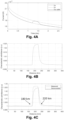
Figs. 4A, 4B and 4C show the results of having implemented the method on the electric conductors ofFig. 3 . - Present invention provides a condition monitoring method of electric conductors (e.g. cables, transmission lines, etc.) based on time-domain estimation of the characteristic admittance of the electric conductors.
- As seen in
Fig. 1 , a genericelectric conductor 10 comprises afirst end 10A or terminal k, asecond end 10B or terminal m, and a given length. In an embodiment, the method comprises applying a voltage signal to thefirst end 10A to scan the entire length of theconductor 10. Then, a processing unit, in the time domain, measures a current at the first end for a given sampling period that assures that a reflected voltage signal doesn't reach back thefirst end 10A. The processing unit further estimates a characteristic admittance of theconductor 10 using the measured current and the voltage signal and determines a health state parameter of theconductor 10 by means of dividing the estimated characteristic admittance of theconductor 10 by an original characteristic admittance thereof. - In the following a more detailed description of the proposed method is provided.
- In
Fig. 1 ,

first end 10A, Im and Vm are current and voltage atsecond end 10B, Z is the cable series impedance, Y is the cable shunt admittance and I is the cable length. - The current Ik in the frequency domain can be calculated as (1)

- Before the reflection at the
second end 10B, Vm = 0 and Im = 0 and Ik becomes dependent only on the voltage applied on thefirst end 10A (Ik = YcVk ). Thus, the electric conductor's characteristic admittance can be estimated as:
first end 10A and Ik becomes the current measure at the same terminal, both variables in the frequency domain. - For (2) to be valid, the voltage signal should be applied and Ik (in the time-domain) should be measured before the reflected wave reaches back the
first end 10A again. In an embodiment, this sampling period (τf ) between the injection of the signal at thefirst end 10A and the reflected wave reaches back can be calculated as:
- Vk can be an arbitrary signal. If it is a constant DC level, for example, (2) becomes:

- If the
electric conductor 10 has a slight variation of its characteristics, Yc will also vary slightly. Thus, by dividing the estimated characteristic admittance (Ŷc ) by the ideal Yc (that can be calculated from the electric conductor parameters or measured when the electric conductor installed), a new variable called Ŷc,p.u can be calculated to indicated the electric conductor's state of health:
- An important feature of the proposed method is that Ŷc,p.u can be transformed to the time-domain and then related with distance using vf and d. Thus, the variation of the electric conductor's characteristic admittance with distance can be obtained, revealing the electric conductor's state of health along its entire length, as illustrated in
Fig. 2 . - With reference now to
Fig. 3 , therein an example of three differentelectric conductors 10 is shown.Electric conductor 10A is known.Electric conductor 10B is not known but it is known that it is a variation of thecable 10A. For the condition monitoring at a first step, the measured current can be divided by the ideal current (if there was only Ya ), obtaining the variation as a result. Then, at a second step, since the travelling wave speed of theelectric conductor 10A is known, it can be considered that said speed does not change to much and relate time with distance using the travelling wave speed. The results of the above yields to the graphs shown inFig. 4A and 4B . - However, the wave after the first and second steps is damped by the electric conductor. The electric conductor acts like a low-pass filter. Thus, to make the admittance variation clearer, at a third step the propagation function of the electric conductor can be used to deconvolute the measured signal (deconvolute = inverse of filter to get the original signal).
Fig. 4C shows the result of the deconvolution. - The present invention has been described in particular detail with respect to specific possible embodiments. Those of skill in the art will appreciate that the invention may be practiced in other embodiments. For example, the nomenclature used for components, capitalization of component designations and terms, the attributes, data structures, or any other programming or structural aspect is not significant, mandatory, or limiting, and the mechanisms that implement the invention or its features can have various different names, formats, and/or protocols. Further, the system and/or functionality of the invention may be implemented via various combinations of software and hardware, as described, or entirely in software elements. Also, particular divisions of functionality between the various components described herein are merely exemplary, and not mandatory or significant. Consequently, functions performed by a single component may, in other embodiments, be performed by multiple components, and functions performed by multiple components may, in other embodiments, be performed by a single component.
- Certain aspects of the present invention include process steps or operations and instructions described herein in an algorithmic and/or algorithmic-like form. It should be noted that the process steps and/or operations and instructions of the present invention can be embodied in software, firmware, and/or hardware, and when embodied in software, can be downloaded to reside on and be operated from different platforms used by real-time network operating systems.
- The scope of the present invention is defined in the following set of claims.
Claims (8)
- A condition monitoring method of an electric conductor, the conductor (10) comprising a cable, a transmission line, or at least one segment of a cable/transmission line, and the conductor (10) having a first end (10A), a second end (10B), and a given length, the method comprising:scanning the entire length of the conductor (10) by means of applying a voltage signal to the first end (10A) of the conductor (10) and by measuring, by a processor, in the time domain, a current at the first end (10A) for a given sampling period, said given sampling period assuring that a reflected voltage signal doesn't reach back the first end (10A);estimating, by a processor, a characteristic admittance of the conductor (10) using the measured current and the voltage signal; anddetermining, by a processor, a health state parameter of the conductor (10) by dividing the estimated characteristic admittance of the conductor (10) by an original characteristic admittance of the conductor (10), the original characteristic admittance being calculated from parameters associated to the conductor (10) or measured when the conductor (10) is installed.
- The method of claim 1, wherein the given sampling period comprises two-times the time interval the voltage signal travels along the conductor (10).
- The method of claim 1 or 2, wherein the voltage signal comprises a DC voltage pulse signal.
- The method of any one of the previous claims, further comprising transforming the health state parameter to the time-domain and further relating the transformed health state parameter with distance using at least the applied voltage signal and the given length of conductor (10).
- The method of any one of the previous claims, further comprising deconvoluting the estimated characteristic admittance of the conductor (10) using a propagation function of the conductor (10).
- The method of claim 1, wherein the scanning is continuously performed.
- The method of claim 1, further comprising comparing the determined health state parameter of the conductor with a threshold, and providing an alarm if the determined health state parameter is equal or above the threshold.
- A non-transitory computer readable medium comprising code instructions that when executed by at least one processor of a computer system implement a method according to claim 1.
Priority Applications (2)
| Application Number | Priority Date | Filing Date | Title |
|---|---|---|---|
| ES22383203T ES3042387T3 (en) | 2022-12-13 | 2022-12-13 | Condition monitoring method of an electric conductor |
| EP22383203.1A EP4386394B1 (en) | 2022-12-13 | 2022-12-13 | Condition monitoring method of an electric conductor |
Applications Claiming Priority (1)
| Application Number | Priority Date | Filing Date | Title |
|---|---|---|---|
| EP22383203.1A EP4386394B1 (en) | 2022-12-13 | 2022-12-13 | Condition monitoring method of an electric conductor |
Publications (3)
| Publication Number | Publication Date |
|---|---|
| EP4386394A1 true EP4386394A1 (en) | 2024-06-19 |
| EP4386394C0 EP4386394C0 (en) | 2025-07-02 |
| EP4386394B1 EP4386394B1 (en) | 2025-07-02 |
Family
ID=84537235
Family Applications (1)
| Application Number | Title | Priority Date | Filing Date |
|---|---|---|---|
| EP22383203.1A Active EP4386394B1 (en) | 2022-12-13 | 2022-12-13 | Condition monitoring method of an electric conductor |
Country Status (2)
| Country | Link |
|---|---|
| EP (1) | EP4386394B1 (en) |
| ES (1) | ES3042387T3 (en) |
Cited By (1)
| Publication number | Priority date | Publication date | Assignee | Title |
|---|---|---|---|---|
| CN120121935A (en) * | 2025-02-17 | 2025-06-10 | 华中科技大学 | A method for evaluating the degree of local defects in cables based on impedance spectroscopy |
Citations (12)
| Publication number | Priority date | Publication date | Assignee | Title |
|---|---|---|---|---|
| US5650728A (en) | 1995-04-03 | 1997-07-22 | Hubbell Incorporated | Fault detection system including a capacitor for generating a pulse and a processor for determining admittance versus frequency of a reflected pulse |
| US7977950B2 (en) | 2008-03-25 | 2011-07-12 | Radiodetection Ltd. | Time-domain reflectometer |
| CN103018627A (en) | 2012-10-25 | 2013-04-03 | 福建省电力有限公司 | Adaptive fault type fault line detection method for non-effectively earthed system |
| CN106383296A (en) | 2016-11-02 | 2017-02-08 | 华北电力大学(保定) | Improved impedance type active distribution network fault location algorithm based on phasor analysis |
| CN106841919A (en) | 2017-01-25 | 2017-06-13 | 南京磐能电力科技股份有限公司 | Based on the high-precision transmission line method of single end distance measurement that triangle is calculated |
| US20170199237A1 (en) * | 2016-01-13 | 2017-07-13 | Siemens Aktiengesellschaft | Method, device and system for determining the fault location of a fault on a line of an electrical energy supply network |
| DE102017214996A1 (en) | 2017-08-28 | 2019-02-28 | Siemens Aktiengesellschaft | Method for determining the distance of a reflection point on an electrical conductor |
| KR101986491B1 (en) | 2018-05-31 | 2019-06-10 | 장찬희 | Apparatus for detecting cable failure place distance and direction |
| WO2019112258A1 (en) * | 2017-12-05 | 2019-06-13 | 전명수 | Device for diagnosing and method for diagnosing deterioration state of cable |
| WO2021023478A1 (en) | 2019-08-06 | 2021-02-11 | Commissariat A L'energie Atomique Et Aux Energies Alternatives | Method and system for monitoring a network of cables, via principal component analysis |
| CN113075501A (en) | 2021-03-26 | 2021-07-06 | 华中科技大学 | Cable fault positioning method and system based on impedance spectrum periodic characteristics |
| CN113253049A (en) | 2021-04-29 | 2021-08-13 | 国网冀北电力有限公司唐山供电公司 | Power distribution network local fault section positioning and active distance measuring device and method |
-
2022
- 2022-12-13 EP EP22383203.1A patent/EP4386394B1/en active Active
- 2022-12-13 ES ES22383203T patent/ES3042387T3/en active Active
Patent Citations (12)
| Publication number | Priority date | Publication date | Assignee | Title |
|---|---|---|---|---|
| US5650728A (en) | 1995-04-03 | 1997-07-22 | Hubbell Incorporated | Fault detection system including a capacitor for generating a pulse and a processor for determining admittance versus frequency of a reflected pulse |
| US7977950B2 (en) | 2008-03-25 | 2011-07-12 | Radiodetection Ltd. | Time-domain reflectometer |
| CN103018627A (en) | 2012-10-25 | 2013-04-03 | 福建省电力有限公司 | Adaptive fault type fault line detection method for non-effectively earthed system |
| US20170199237A1 (en) * | 2016-01-13 | 2017-07-13 | Siemens Aktiengesellschaft | Method, device and system for determining the fault location of a fault on a line of an electrical energy supply network |
| CN106383296A (en) | 2016-11-02 | 2017-02-08 | 华北电力大学(保定) | Improved impedance type active distribution network fault location algorithm based on phasor analysis |
| CN106841919A (en) | 2017-01-25 | 2017-06-13 | 南京磐能电力科技股份有限公司 | Based on the high-precision transmission line method of single end distance measurement that triangle is calculated |
| DE102017214996A1 (en) | 2017-08-28 | 2019-02-28 | Siemens Aktiengesellschaft | Method for determining the distance of a reflection point on an electrical conductor |
| WO2019112258A1 (en) * | 2017-12-05 | 2019-06-13 | 전명수 | Device for diagnosing and method for diagnosing deterioration state of cable |
| KR101986491B1 (en) | 2018-05-31 | 2019-06-10 | 장찬희 | Apparatus for detecting cable failure place distance and direction |
| WO2021023478A1 (en) | 2019-08-06 | 2021-02-11 | Commissariat A L'energie Atomique Et Aux Energies Alternatives | Method and system for monitoring a network of cables, via principal component analysis |
| CN113075501A (en) | 2021-03-26 | 2021-07-06 | 华中科技大学 | Cable fault positioning method and system based on impedance spectrum periodic characteristics |
| CN113253049A (en) | 2021-04-29 | 2021-08-13 | 国网冀北电力有限公司唐山供电公司 | Power distribution network local fault section positioning and active distance measuring device and method |
Cited By (1)
| Publication number | Priority date | Publication date | Assignee | Title |
|---|---|---|---|---|
| CN120121935A (en) * | 2025-02-17 | 2025-06-10 | 华中科技大学 | A method for evaluating the degree of local defects in cables based on impedance spectroscopy |
Also Published As
| Publication number | Publication date |
|---|---|
| ES3042387T3 (en) | 2025-11-20 |
| EP4386394C0 (en) | 2025-07-02 |
| EP4386394B1 (en) | 2025-07-02 |
Similar Documents
| Publication | Publication Date | Title |
|---|---|---|
| AU2007273231B2 (en) | Detection and monitoring of partial discharge of a power line | |
| KR102014582B1 (en) | Apparatus for processing reflected wave | |
| EP1932006B1 (en) | System and method for monitoring of electrical cables | |
| CN104937427B (en) | Method and system for monitoring cable status | |
| CN103930789B (en) | Device and method for remote monitoring of partial discharges in electrical equipment | |
| US9046563B2 (en) | Arcing event detection | |
| KR101570506B1 (en) | Apparatus and method for detecting cable fault location and impedance using linear chirp reflectometry | |
| US11061060B2 (en) | Method and system for locating defects on an electric cable | |
| Cavallini et al. | A novel method to locate PD in polymeric cable systems based on amplitude-frequency (AF) map | |
| EP4386394B1 (en) | Condition monitoring method of an electric conductor | |
| US20100010761A1 (en) | Method and device for monitoring a system | |
| JP2011242206A (en) | Insulation deterioration diagnosis method and insulation deterioration diagnosis device of power cable | |
| KR101984432B1 (en) | Diagnosis device for monitoring degradation of cable and diagnosis method thereof | |
| WO2004001430A1 (en) | Electric power line on-line diagnostic method | |
| EP4413384B1 (en) | A method of detecting a partial discharge signal | |
| Jeon et al. | Cable fault and assessment using multiple frequency autoencoder regression-based reflectometry | |
| KR101958299B1 (en) | Apparatus for processing reflected wave | |
| JP3629424B2 (en) | CV cable insulation diagnosis method | |
| CN112782538A (en) | Cable partial discharge detection method and device based on ultralow frequency power supply cut-off signal | |
| Chun et al. | Detection of Fault Location of COAX Cable with Branch using SSTDR | |
| Kho et al. | Application to Time-Frequency Domain Reflectometry for Load Impedance Measurement | |
| JPH1019964A (en) | Deterioration section determination method for cable lines |
Legal Events
| Date | Code | Title | Description |
|---|---|---|---|
| PUAI | Public reference made under article 153(3) epc to a published international application that has entered the european phase |
Free format text: ORIGINAL CODE: 0009012 |
|
| STAA | Information on the status of an ep patent application or granted ep patent |
Free format text: STATUS: THE APPLICATION HAS BEEN PUBLISHED |
|
| AK | Designated contracting states |
Kind code of ref document: A1 Designated state(s): AL AT BE BG CH CY CZ DE DK EE ES FI FR GB GR HR HU IE IS IT LI LT LU LV MC ME MK MT NL NO PL PT RO RS SE SI SK SM TR |
|
| STAA | Information on the status of an ep patent application or granted ep patent |
Free format text: STATUS: REQUEST FOR EXAMINATION WAS MADE |
|
| 17P | Request for examination filed |
Effective date: 20241211 |
|
| GRAP | Despatch of communication of intention to grant a patent |
Free format text: ORIGINAL CODE: EPIDOSNIGR1 |
|
| STAA | Information on the status of an ep patent application or granted ep patent |
Free format text: STATUS: GRANT OF PATENT IS INTENDED |
|
| INTG | Intention to grant announced |
Effective date: 20250226 |
|
| GRAS | Grant fee paid |
Free format text: ORIGINAL CODE: EPIDOSNIGR3 |
|
| GRAA | (expected) grant |
Free format text: ORIGINAL CODE: 0009210 |
|
| STAA | Information on the status of an ep patent application or granted ep patent |
Free format text: STATUS: THE PATENT HAS BEEN GRANTED |
|
| AK | Designated contracting states |
Kind code of ref document: B1 Designated state(s): AL AT BE BG CH CY CZ DE DK EE ES FI FR GB GR HR HU IE IS IT LI LT LU LV MC ME MK MT NL NO PL PT RO RS SE SI SK SM TR |
|
| REG | Reference to a national code |
Ref country code: GB Ref legal event code: FG4D |
|
| REG | Reference to a national code |
Ref country code: CH Ref legal event code: EP |
|
| REG | Reference to a national code |
Ref country code: DE Ref legal event code: R096 Ref document number: 602022016845 Country of ref document: DE |
|
| REG | Reference to a national code |
Ref country code: IE Ref legal event code: FG4D |
|
| U01 | Request for unitary effect filed |
Effective date: 20250715 |
|
| U07 | Unitary effect registered |
Designated state(s): AT BE BG DE DK EE FI FR IT LT LU LV MT NL PT RO SE SI Effective date: 20250721 |
|
| REG | Reference to a national code |
Ref country code: ES Ref legal event code: FG2A Ref document number: 3042387 Country of ref document: ES Kind code of ref document: T3 Effective date: 20251120 |
|
| PG25 | Lapsed in a contracting state [announced via postgrant information from national office to epo] |
Ref country code: IS Free format text: LAPSE BECAUSE OF FAILURE TO SUBMIT A TRANSLATION OF THE DESCRIPTION OR TO PAY THE FEE WITHIN THE PRESCRIBED TIME-LIMIT Effective date: 20251102 |
|
| PG25 | Lapsed in a contracting state [announced via postgrant information from national office to epo] |
Ref country code: NO Free format text: LAPSE BECAUSE OF FAILURE TO SUBMIT A TRANSLATION OF THE DESCRIPTION OR TO PAY THE FEE WITHIN THE PRESCRIBED TIME-LIMIT Effective date: 20251002 |
|
| PG25 | Lapsed in a contracting state [announced via postgrant information from national office to epo] |
Ref country code: HR Free format text: LAPSE BECAUSE OF FAILURE TO SUBMIT A TRANSLATION OF THE DESCRIPTION OR TO PAY THE FEE WITHIN THE PRESCRIBED TIME-LIMIT Effective date: 20250702 |
|
| PG25 | Lapsed in a contracting state [announced via postgrant information from national office to epo] |
Ref country code: GR Free format text: LAPSE BECAUSE OF FAILURE TO SUBMIT A TRANSLATION OF THE DESCRIPTION OR TO PAY THE FEE WITHIN THE PRESCRIBED TIME-LIMIT Effective date: 20251003 |
|
| PG25 | Lapsed in a contracting state [announced via postgrant information from national office to epo] |
Ref country code: CZ Free format text: LAPSE BECAUSE OF FAILURE TO SUBMIT A TRANSLATION OF THE DESCRIPTION OR TO PAY THE FEE WITHIN THE PRESCRIBED TIME-LIMIT Effective date: 20250702 |
|
| U20 | Renewal fee for the european patent with unitary effect paid |
Year of fee payment: 4 Effective date: 20251218 |
|
| PG25 | Lapsed in a contracting state [announced via postgrant information from national office to epo] |
Ref country code: PL Free format text: LAPSE BECAUSE OF FAILURE TO SUBMIT A TRANSLATION OF THE DESCRIPTION OR TO PAY THE FEE WITHIN THE PRESCRIBED TIME-LIMIT Effective date: 20250702 |
|
| PG25 | Lapsed in a contracting state [announced via postgrant information from national office to epo] |
Ref country code: RS Free format text: LAPSE BECAUSE OF FAILURE TO SUBMIT A TRANSLATION OF THE DESCRIPTION OR TO PAY THE FEE WITHIN THE PRESCRIBED TIME-LIMIT Effective date: 20251002 |
|
| PG25 | Lapsed in a contracting state [announced via postgrant information from national office to epo] |
Ref country code: SM Free format text: LAPSE BECAUSE OF FAILURE TO SUBMIT A TRANSLATION OF THE DESCRIPTION OR TO PAY THE FEE WITHIN THE PRESCRIBED TIME-LIMIT Effective date: 20250702 |
|
| PGFP | Annual fee paid to national office [announced via postgrant information from national office to epo] |
Ref country code: ES Payment date: 20260127 Year of fee payment: 4 |
|
| PG25 | Lapsed in a contracting state [announced via postgrant information from national office to epo] |
Ref country code: SK Free format text: LAPSE BECAUSE OF FAILURE TO SUBMIT A TRANSLATION OF THE DESCRIPTION OR TO PAY THE FEE WITHIN THE PRESCRIBED TIME-LIMIT Effective date: 20250702 |
|
| PLBE | No opposition filed within time limit |
Free format text: ORIGINAL CODE: 0009261 |
|
| STAA | Information on the status of an ep patent application or granted ep patent |
Free format text: STATUS: NO OPPOSITION FILED WITHIN TIME LIMIT |