EP4386281A1 - Refrigerant storage container, and refrigeration cycle device provided with said refrigerant storage container - Google Patents
Refrigerant storage container, and refrigeration cycle device provided with said refrigerant storage container Download PDFInfo
- Publication number
- EP4386281A1 EP4386281A1 EP21953489.8A EP21953489A EP4386281A1 EP 4386281 A1 EP4386281 A1 EP 4386281A1 EP 21953489 A EP21953489 A EP 21953489A EP 4386281 A1 EP4386281 A1 EP 4386281A1
- Authority
- EP
- European Patent Office
- Prior art keywords
- refrigerant
- main body
- storage container
- inflow pipe
- container main
- Prior art date
- Legal status (The legal status is an assumption and is not a legal conclusion. Google has not performed a legal analysis and makes no representation as to the accuracy of the status listed.)
- Withdrawn
Links
Images

Classifications
-
- F—MECHANICAL ENGINEERING; LIGHTING; HEATING; WEAPONS; BLASTING
- F25—REFRIGERATION OR COOLING; COMBINED HEATING AND REFRIGERATION SYSTEMS; HEAT PUMP SYSTEMS; MANUFACTURE OR STORAGE OF ICE; LIQUEFACTION SOLIDIFICATION OF GASES
- F25B—REFRIGERATION MACHINES, PLANTS OR SYSTEMS; COMBINED HEATING AND REFRIGERATION SYSTEMS; HEAT PUMP SYSTEMS
- F25B43/00—Arrangements for separating or purifying gases or liquids; Arrangements for vaporising the residuum of liquid refrigerant, e.g. by heat
- F25B43/006—Accumulators
-
- B—PERFORMING OPERATIONS; TRANSPORTING
- B01—PHYSICAL OR CHEMICAL PROCESSES OR APPARATUS IN GENERAL
- B01D—SEPARATION
- B01D19/00—Degasification of liquids
- B01D19/0042—Degasification of liquids modifying the liquid flow
-
- F—MECHANICAL ENGINEERING; LIGHTING; HEATING; WEAPONS; BLASTING
- F25—REFRIGERATION OR COOLING; COMBINED HEATING AND REFRIGERATION SYSTEMS; HEAT PUMP SYSTEMS; MANUFACTURE OR STORAGE OF ICE; LIQUEFACTION SOLIDIFICATION OF GASES
- F25B—REFRIGERATION MACHINES, PLANTS OR SYSTEMS; COMBINED HEATING AND REFRIGERATION SYSTEMS; HEAT PUMP SYSTEMS
- F25B13/00—Compression machines, plants or systems, with reversible cycle
-
- F—MECHANICAL ENGINEERING; LIGHTING; HEATING; WEAPONS; BLASTING
- F25—REFRIGERATION OR COOLING; COMBINED HEATING AND REFRIGERATION SYSTEMS; HEAT PUMP SYSTEMS; MANUFACTURE OR STORAGE OF ICE; LIQUEFACTION SOLIDIFICATION OF GASES
- F25B—REFRIGERATION MACHINES, PLANTS OR SYSTEMS; COMBINED HEATING AND REFRIGERATION SYSTEMS; HEAT PUMP SYSTEMS
- F25B2400/00—Component parts or details not otherwise provided for in this subclass
- F25B2400/23—Separators
Definitions
- the present disclosure relates to a refrigerant storage container configured to separate two-phase gas-liquid refrigerant into gas refrigerant and liquid refrigerant and to store the liquid refrigerant in the container, and also relates to a refrigeration cycle apparatus provided with the refrigerant storage container.
- Patent Literature 1 discloses a refrigerant storage container that includes a container main body, an inflow pipe through which two-phase gas-liquid refrigerant flows into the container main body, and an outflow pipe through which gas refrigerant flows from the container main body to the outside of the container main body.
- the container main body is a cylindrical body and is horizontally oriented such that its longitudinal direction is parallel to a horizontal direction.
- the inflow pipe provided in the container main body has a distal end having an angled shape and is configured to reduce the inflow velocity of the two-phase gas-liquid refrigerant which flows into the container main body.
- Patent Literature 1 Japanese Patent No. 3163312
- Patent Literature 1 describes a configuration in which the two-phase gas-liquid refrigerant is caused to flow into the container only through the distal end of the inflow pipe provided in the container main body.
- the two-phase gas-liquid refrigerant which flows out from the distal end of the inflow pipe vigorously strikes against an inner wall surface of the container main body without being dispersed. Then, the two-phase gas-liquid refrigerant flows downward in the container main body, strikes concentratedly against part of the liquid refrigerant stored in lower part of the container main body, and waves the liquid refrigerant, as a result of which a surface of the liquid refrigerant may roll up along the inner wall surface of the container main body.
- the rolled-up liquid refrigerant or flying droplets may reach the outflow pipe and enter along with gas refrigerant a compressor. If the liquid refrigerant excessively flows out from the container and flows together with the gas refrigerant into the compressor, refrigerating machine oil in a shell of the compressor may be diluted with the liquid refrigerant, causing seizure at sliding parts of the compressor.
- the present disclosure is applied to solve the above problem, and relates to a refrigerant storage container that is horizontally oriented, causes liquid refrigerant separated from gas refrigerant to be efficiently stored in the container, and reduces an outflow of the stored liquid refrigerant to prevent dilution of refrigerating machine oil that would be caused by the flow of the liquid refrigerant which flows together with the gas refrigerant into a compressor, and ensure the reliability of the compressor, and also relates to a refrigeration cycle apparatus including the refrigerant storage container.
- a refrigerant storage container separates two-phase gas-liquid refrigerant into gas refrigerant and liquid refrigerant, and stores the liquid refrigerant in the refrigerant storage container.
- the refrigerant storage container includes: a horizontally oriented container main body that is a sealed cylindrical body and is provided such that a longitudinal direction of the container main body is a horizontal direction; an inflow pipe which is connected to the container main body and through which the two-phase gas-liquid refrigerant flows into the container main body; and an outflow pipe which is connected to the container main body and through which gas refrigerant and liquid refrigerant flow out from the container main body to an outside of the container main body.
- the inflow pipe has an extension part that extends in the longitudinal direction of the container main body.
- the extension part has a discharge hole that is formed along an axial direction of the inflow pipe and that causes an inside of the inflow pipe to communicate with an outside of the inflow pipe, thereby allowing the two-phase gas-liquid refrigerant to flow into the container main body.
- a refrigeration cycle apparatus includes the above refrigerant storage container and a compressor that is connected to the refrigerant storage container by the outflow pipe.
- the extension part extending in the longitudinal direction of the container main body includes the discharge hole or discharge holes which are formed along the axial direction of the inflow pipe and which cause the inside of the inflow pipe to communicate with the outside of the inflow pipe, thereby allowing the two-phase gas-liquid refrigerant to flow into the container main body.
- the discharge hole or discharge holes which are formed along the axial direction of the inflow pipe and which cause the inside of the inflow pipe to communicate with the outside of the inflow pipe, thereby allowing the two-phase gas-liquid refrigerant to flow into the container main body.
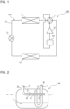
- Fig. 1 is a refrigerant circuit diagram of the refrigeration cycle apparatus 100 including the refrigerant storage container 101 according to Embodiment 1.
- the refrigeration cycle apparatus 100 includes a refrigerant circuit 200 in which a compressor 10, a flow switching device 11, an outdoor heat exchanger 12, an expansion mechanism 13, an indoor heat exchanger 14, and the refrigerant storage container 101 are sequentially connected by refrigerant pipes 15 and in which refrigerant is circulated.
- the compressor 10 sucks the refrigerant, compresses the sucked refrigerant to change it into high-temperature and high-pressure refrigerant, and discharges the high-temperature and high-pressure refrigerant.
- the compressor 10 is, for example, an inverter compressor.
- the refrigerant discharged from the compressor 10 flows into the outdoor heat exchanger 12 or the indoor heat exchanger 14.
- the flow switching device 11 is, for example, a four-way valve, and has a function of switching a refrigerant passage to be used, between refrigerant passages.
- the flow switching device 11 switches the refrigerant passage such that a refrigerant discharge side of the compressor 10 is connected to a gas side of the outdoor heat exchanger 12 and a refrigerant suction side of the compressor 10 is connected to a gas side of the indoor heat exchanger 14.
- the flow switching device 11 switches the flow passage such that the refrigerant discharge side of the compressor 10 is connected to the gas side of the indoor heat exchanger 14 and the refrigerant suction side of the compressor 10 is connected to the gas side of the outdoor heat exchanger 12.
- the flow switching device 11 may be a combination of two-way valves or three-way valves.
- the outdoor heat exchanger 12 operates as a condenser and causes heat exchange to be performed between refrigerant discharged from the compressor 10 and air.
- the outdoor heat exchanger 12 operates as an evaporator and causes heat exchange to be performed between refrigerant which flows out from the expansion mechanism 13 and air.
- the outdoor heat exchanger 12 takes in outdoor air sent by a fan, and lets out air subjected to heat exchange with the refrigerant to the outside of the outdoor heat exchanger 12.
- the expansion mechanism 13 reduces the pressure of refrigerant that flows in the refrigerant circuit to expand the refrigerant, and is, for example, an electronic expansion valve whose opening degree is variably controlled.
- the indoor heat exchanger 14 operates as an evaporator and causes heat exchange to be performed between refrigerant which flows out from the expansion mechanism 13 and air.
- the indoor heat exchanger 14 operates as a condenser and causes heat exchange to be performed between refrigerant discharged from the compressor 10 and air.
- the indoor heat exchanger 14 takes in indoor air sent by a fan, and supplies air subjected to heat exchange with the refrigerant to an indoor space.
- the refrigerant storage container 101 is provided upstream of a suction port of the compressor 10.
- the refrigerant storage container 101 separates two-phase gas-liquid refrigerant which flows out from the evaporator, into gas refrigerant and liquid refrigerant 4, and stores the liquid refrigerant 4 in a lower space in the container.
- refrigerant to be sucked into the compressor 10 is a superheated gas.
- the refrigeration cycle apparatus 100 depends on a refrigerant distribution in the circuit, and gas refrigerant containing the liquid refrigerant 4 may be sucked into the compressor 10.
- the refrigerant storage container 101 which stores the liquid refrigerant 4 separated from the gas refrigerant is provided upstream of the suction port of the compressor 10.
- High-temperature and high-pressure gas refrigerant discharged from the compressor 10 passes through the flow switching device 11, flows to the outdoor heat exchanger 12, and exchanges heat with air to condense and liquefy.
- the refrigerant that has condensed and liquefied is reduced in pressure by the expansion mechanism 13 to change into low-pressure two-phase gas-liquid refrigerant.
- the refrigerant then flows to the indoor heat exchanger 14, and exchanges heat with air to gasify.
- the refrigerant that has gasified passes through the flow switching device 11 and is sucked into the compressor 10 via the refrigerant storage container 101.
- High-temperature and high-pressure gas refrigerant discharged from the compressor 10 passes through the flow switching device 11, flows to the indoor heat exchanger 14, and exchanges heat with air to condense and liquefy.
- the refrigerant that has condensed and liquefied is reduced in pressure by the expansion mechanism 13 to change into low-pressure two-phase gas-liquid refrigerant.
- the refrigerant then flows to the outdoor heat exchanger 12 and exchanges heat with air to gasify.
- the refrigerant that has gasified passes through the flow switching device 11 and is sucked into the compressor 10 via the refrigerant storage container 101.
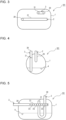
- Fig. 2 is a front view of an internal configuration of the refrigerant storage container 101 according to Embodiment 1.
- Fig. 3 is a plan view of the internal configuration of the refrigerant storage container 101 according to Embodiment 1.
- Fig. 4 illustrates the internal configuration of the refrigerant storage container 101 as viewed in a direction A in Fig. 2 .
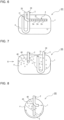
- Fig. 5 is a front view of an internal configuration of a first modification of the refrigerant storage container 101 according to Embodiment 1.
- Fig. 6 is a front view of an internal configuration of a second modification of the refrigerant storage container 101 according to Embodiment 1.
- the refrigerant storage container 101 includes a container main body 1, an inflow pipe 2, and an outflow pipe 3.
- the container main body 1 forms an outer casing of the refrigerant storage container 101.
- the container main body 1 is a sealed cylindrical body and is horizontally oriented such that its longitudinal direction is parallel to a horizontal direction.
- Two-phase gas-liquid refrigerant that flows out from the evaporator flows into the container main body 1 through the inflow pipe 2.
- the two-phase gas-liquid refrigerant contains the refrigerating machine oil.
- the inflow pipe 2 is provided to cause the two-phase gas-liquid refrigerant that flows out from the evaporator to flow into the container main body 1.
- the inflow pipe 2 is L-shaped in the container main body 1, and has an inlet part 20 connected to an upper side of the container main body 1 and an extension part 21 that extends along the longitudinal direction of the container main body 1 in the horizontal direction. An end face of the extension part 21 is closed. It is not indispensable that the extension part 21 extends horizontally. For example, the extension part 21 may be slightly inclined in an up-down direction. In addition, it is not indispensable that the end face of the extension part 21 is completely closed. The end face of the extension part 21 may have an opening through which the two-phase gas-liquid refrigerant flows into the container main body 1.
- discharge holes 2a are formed and arranged along an axial direction of the extension part 21.
- the discharge holes 2a each cause the inside of the inflow pipe 2 to communicate with the outside of the inflow pipe 2, and each allow the two-phase gas-liquid refrigerant to flow into the container main body 1.
- the discharge holes 2a are arranged at regular intervals along the axial direction.
- the discharge holes 2a face an inner wall surface of the container main body 1 in the horizontal direction.
- the discharge holes 2a are located in both side surfaces of the extension part 21 that are located opposite to each other.
- the discharge holes 2a have, for example, a circular shape.
- the total area of the discharge holes 2a be larger than or equal to a passage cross-sectional area of the inflow pipe 2. This is because in the case where the total area of the discharge holes 2a is larger than or equal to the passage cross-sectional area, it is possible to reduce the velocity of two-phase gas-liquid refrigerant that flows out from the discharge holes 2a.
- the discharge holes 2a may be formed in only one side surface of the extension part 21.
- Each of the discharge holes 2a may have, for example, an elliptical shape, an oval shape, or a rectangular shape, or may be formed in the shape of a spiral along the axial direction, or may have any other shape.
- the arrangement and size of the discharge holes 2a are appropriately changed depending on, for example, the size of the container main body 1 or the size, shape, and length of the inflow pipe 2.
- the discharge holes 2a formed in the both side surfaces of the extension part 21 may be arranged in a staggered manner such that any associated ones of the discharge holes 2a that are located opposite to each other are not aligned with each other.
- the discharge holes 2a are provided only in the extension part 21, it is not limiting.
- the discharge holes 2a may be formed in the inlet part 20 or in the bent part which connects the extension part 21 and the inlet part 20.
- the discharge holes 2a may be formed to face the inner wall surface of the container main body 1 in the horizontal direction, the discharge holes 2a may be formed to face upward, downward, or obliquely in the container main body 1, for example.
- the inflow pipe 2 is connected to the upper surface of the container main body 1, but it is not limiting. As illustrated in Fig.
- the inflow pipe 2 may be a straight pipe, and the inlet part 20 may be connected to a side surface of the container main body 1 in the horizontal direction. Although it is not illustrated, the inlet part 20 may be connected to a lower surface of the container main body 1.
- the outflow pipe 3 is provided to cause the gas refrigerant and the liquid refrigerant 4 to flow from the container main body 1 to the outside of the container main body 1.
- the outflow pipe 3 is U-shaped in the container main body 1 and has one end 30 connected to the upper surface of the container main body 1.
- the gas refrigerant separated from the liquid refrigerant 4 flows into the outflow pipe 3 through the other end 31 of the outflow pipe 3, flows to the outside of the container main body 1, and is then sucked into the compressor 10.
- the other end 31 of the outflow pipe 3 is provided at a higher position than the extension part 21 of the inflow pipe 2. This configuration is intended to reduce the probability that the liquid refrigerant 4 of the two-phase gas-liquid refrigerant which flows out from the discharge holes 2a will flow into the outflow pipe 3 through the other end 31 of the outflow pipe 3.
- the outflow pipe 3 is connected to the upper surface of the container main body 1, it is not limiting. Although it is not illustrated, the outflow pipe 3 may be L-shaped in the container main body 1. The one end 30 of the outflow pipe 3 may be connected to a side surface of the container main body 1 in the horizontal direction or may be connected to the lower surface of the container main body 1.
- the other end 31 of the outflow pipe 3 may be provided upstream of the most upstream one of the discharge holes 2a.
- a large number of droplets of the two-phase gas-liquid refrigerant are made by inertial force to flow out from part of the inflow pipe 2 that is located on a downstream side.
- Such a configuration is effective particularly in the case where the end face of the extension part 21 has an opening through which the two-phase gas-liquid refrigerant flows into the container main body 1.
- the two-phase gas-liquid refrigerant flows into the container main body 1 through the inflow pipe 2.
- the two-phase gas-liquid refrigerant which flows through the inflow pipe 2 flows into the container main body 1 through the discharge holes 2a provided in the inflow pipe 2.
- the two-phase gas-liquid refrigerant which has flowed through the discharge holes 2a strikes against the inner wall surface of the container main body 1 and is thus separated into gas refrigerant and liquid refrigerant 4.
- the gas refrigerant which has a low density, stays in an upper space in the container main body 1, flows to the outside of the container main body 1 through the other end 31 of the outflow pipe 3, and is then sucked into the compressor 10.
- the liquid refrigerant 4, which has a high density flows to and is stored in the lower space in the container main body 1 under the effect of gravity.
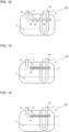
- Fig. 7 is a front view of an internal configuration of an existing refrigerant storage container 105.
- Fig. 8 illustrates the internal configuration of the refrigerant storage container 105 as viewed in a direction B in Fig. 7 .
- arrows indicate the flow direction of refrigerant that flows out from the end of the inflow pipe 2.
- the existing refrigerant storage container 105 has a configuration in which two-phase gas-liquid refrigerant flows into the container main body 1 only through the end of the inflow pipe 2 provided in the container main body 1.
- the two-phase gas-liquid refrigerant which has flowed out from the end of the inflow pipe 2 vigorously strikes against the inner wall surface of the container main body 1 without being dispersed.
- the two-phase gas-liquid refrigerant which has struck against the inner wall surface flows downward in the container main body 1, and strikes concentratedly against part of the liquid refrigerant 4 stored in the lower space in the container main body 1.
- the liquid refrigerant 4 waves as it turns up and down, such that the surface of the liquid refrigerant rolls up along the inner wall surface of the container main body 1.
- the rolled-up liquid refrigerant 4 or flying droplets 40 may reach the other end 31 of the outflow pipe 3 and flows together with the gas refrigerant into the compressor 10. If the liquid refrigerant 4 excessively flows out of the container and flows together with the gas refrigerant into the compressor 10, the refrigerating machine oil in the shell of the compressor 10 may be diluted with the liquid refrigerant, causing seizure to occur at the sliding parts of the compressor 10.
- the refrigerant storage container 101 includes: the horizontally oriented container main body 1, which is a sealed cylindrical body and is provided such that its longitudinal direction parallel to the horizontal direction; the inflow pipe 2 which is connected to the container main body 1 and through which the two-phase gas-liquid refrigerant flows into the container main body 1; and the outflow pipe 3 which is connected to the container main body 1 and through which the gas refrigerant and the liquid refrigerant 4 flow from the container main body 1 to the outside of the container main body 1.
- the inflow pipe 2 has the extension part 21 which extends along the longitudinal direction of the container main body 1.
- the discharge holes 2a are formed and arranged along the axial direction. The discharge holes 2a cause the inside of the inflow pipe 2 to communicate with the outside of the inflow pipe 2, and allow the two-phase gas-liquid refrigerant to flow into the container main body 1.
- Fig. 9 is an explanatory view that illustrates the refrigerant storage container 101 according to Embodiment 1 and that is used in explanation of how the two-phase gas-liquid refrigerant flows out from the discharge holes 2a.
- arrow indicates the flow direction of the refrigerant which has flowed out from the discharge holes 2a.
- the two-phase gas-liquid refrigerant can be caused to flow out from the discharge holes 2a formed in the inflow pipe 2, while being dispersed.
- the discharge holes 2a face the inner wall surface of the container main body 1 in the horizontal direction.
- the discharge holes 2a are formed in the both side surfaces of the inflow pipe 2 which are located opposite to each other.
- the two-phase gas-liquid refrigerant that flows out from the discharge holes 2a can be dispersed and made to strike against the liquid refrigerant 4 stored in the lower space in the container main body 1. It is therefore possible to reduce occurrence of waving of the liquid refrigerant 4 that occurs such that the liquid refrigerant 4 rotates in the up-down direction.
- the discharge holes 2a are spaced apart from each other along the axial direction. It is therefore possible to cause the two-phase gas-liquid refrigerant to flow out from the discharge holes 2a formed in the inflow pipe 2, while being dispersed, and to reduce the velocity of the two-phase gas-liquid refrigerant which strikes against the inner wall surface of the container main body 1.
- the end face of the extension part 21 is closed in the container main body 1. It is therefore possible to cause the two-phase gas-liquid refrigerant to flow from the discharge holes 2a located in the inflow pipe 2, while being efficiently dispersed. In this case, it is effective that the total area of the discharge holes 2a be larger than or equal to the passage cross-sectional area of the inflow pipe 2. This is because in such a configuration, it is possible to reduce the velocity of the two-phase gas-liquid refrigerant which flows out from the discharge holes 2a.
- the end 31 of the outflow pipe 3, through which the gas refrigerant flows thereinto, is provided upstream of the most upstream one of the discharge holes 2a.
- a large number of droplets of the two-phase gas-liquid refrigerant can be caused by inertial force to flow out from a downstream side of the inflow pipe 2. Since the other end 31 of the outflow pipe 3, through which the gas refrigerant enters, is provided upstream of the most upstream discharge hole 2a and away from the downstream side of the inflow pipe 2, the flow of droplets into the outflow pipe 3 can be reduced.
- FIG. 10 is a front view of an internal configuration of the refrigerant storage container 102 according to Embodiment 2.
- components that are the same as those in in Embodiment 1 will be denoted by the same reference signs, and their descriptions will thus be omitted as appropriate.
- the refrigerant storage container 102 according to Embodiment 2 differs from the refrigerant storage container 101 according to Embodiment 1 in the configuration of the discharge holes 2a provided in the extension part 21.
- the other components in Embodiment 2 are the same as those in Embodiment 1.
- the discharge holes 2a provided in the extension part 21 in Embodiment 2 are slits that extend in the axial direction.
- the discharge holes 2a face the inner wall surface of the container main body 1 in the horizontal direction.
- the discharge holes 2a are located in both side surfaces of the extension part 21 that are located opposite to each other. In the case where the end face of the extension part 21 is closed, it is preferable that the total area of the discharge holes 2a be larger than or equal to the passage cross-sectional area of the inflow pipe 2.
- discharge holes 2a By forming the discharge holes 2a such that the total area of the discharge holes 2a is larger than or equal to the passage cross-sectional area, it is possible to reduce the velocity of two-phase gas-liquid refrigerant that flows out from the discharge holes 2a.
- the configuration of the discharge holes 2a is not limited to that of the above example in which a single discharge hole 2a is formed in each of the side surfaces along the axial direction, a plurality of discharge holes 2a may be formed in each of the side surfaces such that they are spaced apart from each other along the axial direction.
- the discharge holes 2a are provided only in the extension part 21, but it is not limiting.
- the discharge holes 2a may be provided in the inlet part 20 or in the bent part which connects the extension part 21 and the inlet part 20.
- the discharge holes 2a face the inner wall surface of the container main body 1 in the horizontal direction, the discharge holes 2a may be formed to face upward, downward, or obliquely in the container main body 1, for example.
- the refrigerant storage container 102 also enables the two-phase gas-liquid refrigerant to flow into the container main body 1 while being dispersed from the discharge holes 2a formed in the inflow pipe 2.
- FIG. 11 is a front view of an internal configuration of the refrigerant storage container 103 according to Embodiment 3.
- Fig. 12 is a front view of an internal configuration of a modification of the refrigerant storage container 103 according to Embodiment 3. It should be noted that regarding Embodiment 3, components that are the same as those in Embodiment 1 are denoted by the same reference signs, and their descriptions will thus be omitted as appropriate.
- the refrigerant storage container 103 according to Embodiment 3 differs from the refrigerant storage container 101 according to Embodiment 1 in the discharge holes 2a located in the extension part 21.
- the other components are the same as those in Embodiment 1.
- a plurality of discharge holes 2a are formed in the extension part 21 at regular intervals in the axial direction.
- the discharge holes 2a are formed to have different sizes such that the size of the discharge hole 2a increases in a stepwise manner toward the downstream side of the inflow pipe 2. The more upstream the refrigerant that flows from the discharge hole 2a, the higher the velocity of the refrigerant. If the discharge holes 2a have the same size, the velocities of the refrigerant that flows from the discharge holes 2a may vary, and this may cause the surface of liquid refrigerant to be rolled up.
- the discharge holes 2a are formed to have different sizes such that the size of the discharge hole 2a increases in a stepwise manner toward the downstream side of the inflow pipe 2 in order to equalize the velocities of the refrigerant which flows from the discharge holes 2a.
- the discharge holes 2a face the inner wall surface of the container main body 1 in the horizontal direction.
- the discharge holes 2a are located in each of the both side surfaces of the extension part 21 which are located opposite to each other.
- the total area of the discharge holes 2a be larger than or equal to the passage cross-sectional area of the inflow pipe 2. This is because by forming the discharge holes 2a such that the total area of the discharge holes 2a be larger than or equal to the passage cross-sectional area, it is possible to reduce the velocities of the two-phase gas-liquid refrigerant that flows from the discharge holes 2a.
- the discharge holes 2a have, for example, a circular shape.
- each of the discharge holes 2a may have, for example, an elliptical shape, an oval shape, or a rectangular shape, or may be formed in the shape of a spiral extending along the axial direction.
- the arrangement and size of the discharge holes 2a may be appropriately changed depending on, for example, the size of the container main body 1 or the size, shape, and length of the inflow pipe 2.
- the discharge holes 2a formed in the both side surfaces of the extension part 21 which are located opposite to each other may be formed in a staggered manner such that any associated ones of the discharge holes 2a that are located opposite to each other are not aligned with each other.
- discharge holes 2a on the downstream side of the inflow pipe 2 may be formed to have a larger size than discharge holes 2a on the upstream side of the inflow pipe 2.
- Fig. 12 illustrates by way of example a configuration in which two discharge holes 2a located on the downstream side are larger in size than the other discharge holes 2a, that is, than discharge holes located on the upstream side.
- the discharge holes 2a may be paired such that a plurality of pairs of discharge holes 2a are formed to have different sizes, discharge holes 2a of each pair have the same size, and the hole size of the pair increases in dimension in a stepwise manner.
- the discharge holes 2a are located only in the extension part 21, but it is not limiting.
- the discharge holes 2a may be formed in the inlet part 20 or may be formed in the bent part which connects the extension part 21 and the inlet part 20. Although it is preferable that the discharge holes 2a face the inner wall surface of the container main body 1 in the horizontal direction, the discharge holes 2a may be formed to face upward, downward, or obliquely in the container main body 1, for example.
- the refrigerant storage container 103 also enables the two-phase gas-liquid refrigerant to flow into the container main body 1 while being dispersed from the discharge holes 2a located in the inflow pipe 2.
- the discharge holes 2a are formed to have different sizes such that the size of the discharge hole 2a increases in dimension in a stepwise manner toward the downstream side of the inflow pipe 2.
- discharge holes 2a on the downstream side of the inflow pipe 2 are formed to have a larger size than discharge holes 2a on the upstream side of the inflow pipe 2. Therefore, the refrigerant storage container 103 according to Embodiment 3 can equalize the velocities of the refrigerant which flows out from the discharge holes 2a, and further reduce the degree to which the surface of the liquid refrigerant is rolled up.
- FIG. 13 is a front view of an internal configuration of the refrigerant storage container 104 according to Embodiment 4.
- Fig. 14 is a front view of an internal configuration of a modification of the refrigerant storage container 104 according to Embodiment 4. It should be noted that regarding Embodiment 4, components that are the same as those in Embodiment 1 will be denoted by the same reference signs, and their descriptions will thus be omitted as appropriate.
- the refrigerant storage container 104 according to Embodiment 4 differs from the refrigerant storage container 101 according to Embodiment 1 in the discharge holes 2a formed in the extension part 21.
- the other components are the same as those in Embodiment 1.
- each of the discharge holes 2a formed in the extension part 21 is a slit that extends in the axial direction.
- Each discharge hole 2a increases in dimension in a stepwise manner toward the downstream side of the inflow pipe 2. The more upstream the refrigerant which flows out from the discharge hole 2a, the higher the velocity of the refrigerant. If the discharge hole 2a has a constant dimension, the velocities of refrigerant that flows out from different parts of the discharge hole 2a may vary and the surface of liquid refrigerant may be rolled up.
- the discharge hole 2a is formed such that its dimension increases in a stepwise manner toward the downstream side of the inflow pipe 2, in order to equalize the velocities of the refrigerant which flows from the different parts of the discharge hole 2a.
- the discharge holes 2a face the inner wall surface of the container main body 1 in the horizontal direction.
- the discharge holes 2a are formed in both side surfaces of the extension part 21 that are located opposite to each other. In the case where the end face of the extension part 21 is closed, it is preferable that the total area of the discharge holes 2a be larger than or equal to the passage cross-sectional area of the inflow pipe 2.
- the discharge holes 2a By forming the discharge holes 2a such that the total area of the discharge holes 2a is larger than or equal to the passage cross-sectional area, it is possible to reduce the velocities of the two-phase gas-liquid refrigerant which flows out from the discharge holes 2a.
- each of the discharge holes 2a increases in dimension in a stepwise manner, but it is not limiting.
- the discharge hole 2a may be formed such that part of the discharge hole 2a that is located on the downstream side of the inflow pipe 2 is larger in dimension than part of the discharge hole 2a that is located on the upstream side of the inflow pipe 2.
- the discharge holes 2a are located only in the extension part 21, but it is not limiting.
- the discharge holes 2a may be provided in the inlet part 20 or in the bent part which connects the extension part 21 and the inlet part 20.
- the discharge holes 2a may be formed to face the inner wall surface of the container main body 1 in the horizontal direction, the discharge holes 2a may be formed to face upward, downward, or obliquely in the container main body 1, for example.
- the refrigerant storage container 104 also enables the two-phase gas-liquid refrigerant to flow into the container main body 1 while being dispersed from the discharge holes 2a located in the inflow pipe 2.
- each of the discharge holes 2a increases in dimension in a stepwise manner toward the downstream side of the inflow pipe 2.
- part of the discharge hole 2a that is located on the downstream side of the inflow pipe 2 is larger in dimension than part of the discharge hole 2a that is located on the upstream side of the inflow pipe 2,. Therefore, the refrigerant storage container 103 according to Embodiment 4 can equalize the velocities of the refrigerant which flows from the different parts of the discharge hole 2a and further reduce the degree to which the surface of the liquid refrigerant is rolled up.
- the refrigerant storage containers (101 to 104) and the refrigeration cycle apparatus 100 are described above.
- the configurations of the refrigerant storage containers and the refrigeration cycle apparatus are not limited to those as described above regarding the above embodiments.
- the configurations of the refrigerant storage containers (101 to 104) are not limited to those illustrated in the figures, and the refrigerant storage containers may each include another component.
- the configuration of the refrigeration cycle apparatus 100 is not limited to that illustrated in related ones of the figures, and the refrigeration cycle apparatus 100 may include another component.
- the refrigerant storage containers (101 to 104) and the refrigeration cycle apparatus 100 encompasses the range of design changes and application variations that are normally made by a person with ordinary skill in the art to the extent that they do not depart from the technical concept thereof.
Landscapes
- Engineering & Computer Science (AREA)
- Chemical & Material Sciences (AREA)
- Analytical Chemistry (AREA)
- Power Engineering (AREA)
- Physics & Mathematics (AREA)
- Mechanical Engineering (AREA)
- Thermal Sciences (AREA)
- General Engineering & Computer Science (AREA)
- Chemical Kinetics & Catalysis (AREA)
- Compressor (AREA)
- Air-Conditioning For Vehicles (AREA)
Abstract
Description
- The present disclosure relates to a refrigerant storage container configured to separate two-phase gas-liquid refrigerant into gas refrigerant and liquid refrigerant and to store the liquid refrigerant in the container, and also relates to a refrigeration cycle apparatus provided with the refrigerant storage container.
- In the past, various refrigerant storage containers configured to separate two-phase gas-liquid refrigerant into gas refrigerant and liquid refrigerant and to store the liquid refrigerant in the container have been disclosed and have been put to practical use. For example, Patent Literature 1 discloses a refrigerant storage container that includes a container main body, an inflow pipe through which two-phase gas-liquid refrigerant flows into the container main body, and an outflow pipe through which gas refrigerant flows from the container main body to the outside of the container main body. The container main body is a cylindrical body and is horizontally oriented such that its longitudinal direction is parallel to a horizontal direction. The inflow pipe provided in the container main body has a distal end having an angled shape and is configured to reduce the inflow velocity of the two-phase gas-liquid refrigerant which flows into the container main body.
- Patent Literature 1:
Japanese Patent No. 3163312 - Patent Literature 1 describes a configuration in which the two-phase gas-liquid refrigerant is caused to flow into the container only through the distal end of the inflow pipe provided in the container main body. The two-phase gas-liquid refrigerant which flows out from the distal end of the inflow pipe vigorously strikes against an inner wall surface of the container main body without being dispersed. Then, the two-phase gas-liquid refrigerant flows downward in the container main body, strikes concentratedly against part of the liquid refrigerant stored in lower part of the container main body, and waves the liquid refrigerant, as a result of which a surface of the liquid refrigerant may roll up along the inner wall surface of the container main body. The rolled-up liquid refrigerant or flying droplets may reach the outflow pipe and enter along with gas refrigerant a compressor. If the liquid refrigerant excessively flows out from the container and flows together with the gas refrigerant into the compressor, refrigerating machine oil in a shell of the compressor may be diluted with the liquid refrigerant, causing seizure at sliding parts of the compressor.
- The present disclosure is applied to solve the above problem, and relates to a refrigerant storage container that is horizontally oriented, causes liquid refrigerant separated from gas refrigerant to be efficiently stored in the container, and reduces an outflow of the stored liquid refrigerant to prevent dilution of refrigerating machine oil that would be caused by the flow of the liquid refrigerant which flows together with the gas refrigerant into a compressor, and ensure the reliability of the compressor, and also relates to a refrigeration cycle apparatus including the refrigerant storage container. Solution to Problem
- A refrigerant storage container according to an embodiment of the present disclosure separates two-phase gas-liquid refrigerant into gas refrigerant and liquid refrigerant, and stores the liquid refrigerant in the refrigerant storage container. The refrigerant storage container includes: a horizontally oriented container main body that is a sealed cylindrical body and is provided such that a longitudinal direction of the container main body is a horizontal direction; an inflow pipe which is connected to the container main body and through which the two-phase gas-liquid refrigerant flows into the container main body; and an outflow pipe which is connected to the container main body and through which gas refrigerant and liquid refrigerant flow out from the container main body to an outside of the container main body. The inflow pipe has an extension part that extends in the longitudinal direction of the container main body. The extension part has a discharge hole that is formed along an axial direction of the inflow pipe and that causes an inside of the inflow pipe to communicate with an outside of the inflow pipe, thereby allowing the two-phase gas-liquid refrigerant to flow into the container main body.
- A refrigeration cycle apparatus according to another embodiment of the present disclosure includes the above refrigerant storage container and a compressor that is connected to the refrigerant storage container by the outflow pipe.
- According to the embodiments of the present disclosure, the extension part extending in the longitudinal direction of the container main body includes the discharge hole or discharge holes which are formed along the axial direction of the inflow pipe and which cause the inside of the inflow pipe to communicate with the outside of the inflow pipe, thereby allowing the two-phase gas-liquid refrigerant to flow into the container main body. Thus, it is possible to cause the two-phase gas-liquid refrigerant to flow from the discharge hole or holes into the container main body while being dispersed from the discharge hole or holes. By virtue of this configuration, it is possible to reduce the velocity of the two-phase gas-liquid refrigerant which strikes against an inner wall surface of the container main body, thereby reducing the degree to which the stored liquid refrigerant is rolled up and thus reducing an outflow of the liquid refrigerant from the outflow pipe. Therefore, since an excessive outflow of the stored liquid refrigerant can be reduced, it is possible to prevent dilution of refrigerating machine oil that would be caused by flow of the liquid refrigerant into the compressor, thus ensuring the reliability of the compressor.
-
- [
Fig. 1] Fig. 1 is a refrigerant circuit diagram of a refrigeration cycle apparatus including a refrigerant storage container according to Embodiment 1. - [
Fig. 2] Fig. 2 is a front view of an internal configuration of the refrigerant storage container according to Embodiment 1. - [
Fig. 3] Fig. 3 is a plan view of the internal configuration of the refrigerant storage container according to Embodiment 1 as viewed from above. - [
Fig. 4] Fig. 4 is a diagram of the internal configuration of the refrigerant storage container as viewed in a direction A inFig. 2 . - [
Fig. 5] Fig. 5 is a front view of an internal configuration of a first modification of the refrigerant storage container according to Embodiment 1. - [
Fig. 6] Fig. 6 is a front view of an internal configuration of a second modification of the refrigerant storage container according to Embodiment 1. - [
Fig. 7] Fig. 7 is a front view of an internal configuration of an existing refrigerant storage container. - [
Fig. 8] Fig. 8 illustrates the internal configuration of the refrigerant storage container as viewed in a direction B inFig. 7 . - [
Fig. 9] Fig. 9 is an explanatory view illustrating the refrigerant storage container according to Embodiment 1 and that is used in explanation of how two-phase gas-liquid refrigerant flows from discharge holes. - [
Fig. 10] Fig. 10 is a front view of an internal configuration of a refrigerant storage container according toEmbodiment 2. - [
Fig. 11] Fig. 11 is a front view of an internal configuration of a refrigerant storage container according toEmbodiment 3. - [
Fig. 12] Fig. 12 is a front view of an internal configuration of a modification of the refrigerant storage container according toEmbodiment 3. - [
Fig. 13] Fig. 13 is a front view of an internal configuration of a refrigerant storage container according toEmbodiment 4. - [
Fig. 14] Fig. 14 is a front view of an internal configuration of a modification of the refrigerant storage container according toEmbodiment 4. - Embodiments of the present disclosure will be described below with reference to the figures in the drawings. It should be noted that in each of the figures, components that are the same as or equivalent to those in a previous figure or previous figures are denoted by the same reference signs, and their descriptions will thus be omitted or simplified as appropriate. Furthermore, for example, the shapes, sizes, and arrangement of components as illustrated in each figure can be changed as appropriate.
- First of all, a
refrigeration cycle apparatus 100 including arefrigerant storage container 101 according to Embodiment 1 will be described with reference toFig. 1. Fig. 1 is a refrigerant circuit diagram of therefrigeration cycle apparatus 100 including therefrigerant storage container 101 according to Embodiment 1. - As illustrated in
Fig. 1 , therefrigeration cycle apparatus 100 according to Embodiment 1 includes arefrigerant circuit 200 in which acompressor 10, aflow switching device 11, anoutdoor heat exchanger 12, anexpansion mechanism 13, anindoor heat exchanger 14, and therefrigerant storage container 101 are sequentially connected byrefrigerant pipes 15 and in which refrigerant is circulated. - The
compressor 10 sucks the refrigerant, compresses the sucked refrigerant to change it into high-temperature and high-pressure refrigerant, and discharges the high-temperature and high-pressure refrigerant. Thecompressor 10 is, for example, an inverter compressor. The refrigerant discharged from thecompressor 10 flows into theoutdoor heat exchanger 12 or theindoor heat exchanger 14. - The
flow switching device 11 is, for example, a four-way valve, and has a function of switching a refrigerant passage to be used, between refrigerant passages. In a cooling operation, theflow switching device 11 switches the refrigerant passage such that a refrigerant discharge side of thecompressor 10 is connected to a gas side of theoutdoor heat exchanger 12 and a refrigerant suction side of thecompressor 10 is connected to a gas side of theindoor heat exchanger 14. In a heating operation, theflow switching device 11 switches the flow passage such that the refrigerant discharge side of thecompressor 10 is connected to the gas side of theindoor heat exchanger 14 and the refrigerant suction side of thecompressor 10 is connected to the gas side of theoutdoor heat exchanger 12. It should be noted that theflow switching device 11 may be a combination of two-way valves or three-way valves. - In the cooling operation, the
outdoor heat exchanger 12 operates as a condenser and causes heat exchange to be performed between refrigerant discharged from thecompressor 10 and air. In the heating operation, theoutdoor heat exchanger 12 operates as an evaporator and causes heat exchange to be performed between refrigerant which flows out from theexpansion mechanism 13 and air. Theoutdoor heat exchanger 12 takes in outdoor air sent by a fan, and lets out air subjected to heat exchange with the refrigerant to the outside of theoutdoor heat exchanger 12. - The
expansion mechanism 13 reduces the pressure of refrigerant that flows in the refrigerant circuit to expand the refrigerant, and is, for example, an electronic expansion valve whose opening degree is variably controlled. - In the cooling operation, the
indoor heat exchanger 14 operates as an evaporator and causes heat exchange to be performed between refrigerant which flows out from theexpansion mechanism 13 and air. In the heating operation, theindoor heat exchanger 14 operates as a condenser and causes heat exchange to be performed between refrigerant discharged from thecompressor 10 and air. Theindoor heat exchanger 14 takes in indoor air sent by a fan, and supplies air subjected to heat exchange with the refrigerant to an indoor space. - As illustrated in
Fig. 1 , therefrigerant storage container 101 is provided upstream of a suction port of thecompressor 10. Therefrigerant storage container 101 separates two-phase gas-liquid refrigerant which flows out from the evaporator, into gas refrigerant andliquid refrigerant 4, and stores theliquid refrigerant 4 in a lower space in the container. In therefrigeration cycle apparatus 100, ideally, refrigerant to be sucked into thecompressor 10 is a superheated gas. However, therefrigeration cycle apparatus 100 depends on a refrigerant distribution in the circuit, and gas refrigerant containing theliquid refrigerant 4 may be sucked into thecompressor 10. If theliquid refrigerant 4 is sucked into thecompressor 10, refrigerating machine oil in a shell of thecompressor 10 may be diluted with theliquid refrigerant 4, causing seizure at sliding parts of thecompressor 10. Thus, in order to avoid occurrence of seizure at the sliding parts of thecompressor 10 in therefrigeration cycle apparatus 100, therefrigerant storage container 101 which stores theliquid refrigerant 4 separated from the gas refrigerant is provided upstream of the suction port of thecompressor 10. - The cooling operation of the
refrigeration cycle apparatus 100 will be described. High-temperature and high-pressure gas refrigerant discharged from thecompressor 10 passes through theflow switching device 11, flows to theoutdoor heat exchanger 12, and exchanges heat with air to condense and liquefy. The refrigerant that has condensed and liquefied is reduced in pressure by theexpansion mechanism 13 to change into low-pressure two-phase gas-liquid refrigerant. The refrigerant then flows to theindoor heat exchanger 14, and exchanges heat with air to gasify. The refrigerant that has gasified passes through theflow switching device 11 and is sucked into thecompressor 10 via therefrigerant storage container 101. - The heating operation of the
refrigeration cycle apparatus 100 will be described. High-temperature and high-pressure gas refrigerant discharged from thecompressor 10 passes through theflow switching device 11, flows to theindoor heat exchanger 14, and exchanges heat with air to condense and liquefy. The refrigerant that has condensed and liquefied is reduced in pressure by theexpansion mechanism 13 to change into low-pressure two-phase gas-liquid refrigerant. The refrigerant then flows to theoutdoor heat exchanger 12 and exchanges heat with air to gasify. The refrigerant that has gasified passes through theflow switching device 11 and is sucked into thecompressor 10 via therefrigerant storage container 101. - Next, the
refrigerant storage container 101 according to Embodiment 1 will be described with reference toFigs. 2 to 6 .Fig. 2 is a front view of an internal configuration of therefrigerant storage container 101 according to Embodiment 1.Fig. 3 is a plan view of the internal configuration of therefrigerant storage container 101 according to Embodiment 1.Fig. 4 illustrates the internal configuration of therefrigerant storage container 101 as viewed in a direction A inFig. 2 .Fig. 5 is a front view of an internal configuration of a first modification of therefrigerant storage container 101 according to Embodiment 1.Fig. 6 is a front view of an internal configuration of a second modification of therefrigerant storage container 101 according to Embodiment 1. - As illustrated in
Figs. 2 to 4 , therefrigerant storage container 101 according to Embodiment 1 includes a container main body 1, aninflow pipe 2, and anoutflow pipe 3. The container main body 1 forms an outer casing of therefrigerant storage container 101. The container main body 1 is a sealed cylindrical body and is horizontally oriented such that its longitudinal direction is parallel to a horizontal direction. Two-phase gas-liquid refrigerant that flows out from the evaporator flows into the container main body 1 through theinflow pipe 2. The two-phase gas-liquid refrigerant contains the refrigerating machine oil. - As illustrated in
Fig. 2 , theinflow pipe 2 is provided to cause the two-phase gas-liquid refrigerant that flows out from the evaporator to flow into the container main body 1. In an example illustrated inFig. 2 , theinflow pipe 2 is L-shaped in the container main body 1, and has aninlet part 20 connected to an upper side of the container main body 1 and anextension part 21 that extends along the longitudinal direction of the container main body 1 in the horizontal direction. An end face of theextension part 21 is closed. It is not indispensable that theextension part 21 extends horizontally. For example, theextension part 21 may be slightly inclined in an up-down direction. In addition, it is not indispensable that the end face of theextension part 21 is completely closed. The end face of theextension part 21 may have an opening through which the two-phase gas-liquid refrigerant flows into the container main body 1. - In the
extension part 21,discharge holes 2a are formed and arranged along an axial direction of theextension part 21. The discharge holes 2a each cause the inside of theinflow pipe 2 to communicate with the outside of theinflow pipe 2, and each allow the two-phase gas-liquid refrigerant to flow into the container main body 1. In Embodiment 1, the discharge holes 2a are arranged at regular intervals along the axial direction. The discharge holes 2a face an inner wall surface of the container main body 1 in the horizontal direction. The discharge holes 2a are located in both side surfaces of theextension part 21 that are located opposite to each other. The discharge holes 2a have, for example, a circular shape. - In the case where the end face of the
extension part 21 is closed, it is preferable that the total area of the discharge holes 2a be larger than or equal to a passage cross-sectional area of theinflow pipe 2. This is because in the case where the total area of thedischarge holes 2a is larger than or equal to the passage cross-sectional area, it is possible to reduce the velocity of two-phase gas-liquid refrigerant that flows out from thedischarge holes 2a. - The discharge holes 2a may be formed in only one side surface of the
extension part 21. Each of thedischarge holes 2a may have, for example, an elliptical shape, an oval shape, or a rectangular shape, or may be formed in the shape of a spiral along the axial direction, or may have any other shape. The arrangement and size of the discharge holes 2a are appropriately changed depending on, for example, the size of the container main body 1 or the size, shape, and length of theinflow pipe 2. For example, thedischarge holes 2a formed in the both side surfaces of theextension part 21 may be arranged in a staggered manner such that any associated ones of the discharge holes 2a that are located opposite to each other are not aligned with each other. - Although it is described above that the discharge holes 2a are provided only in the
extension part 21, it is not limiting. The discharge holes 2a may be formed in theinlet part 20 or in the bent part which connects theextension part 21 and theinlet part 20. Furthermore, although it is preferable that the discharge holes 2a be formed to face the inner wall surface of the container main body 1 in the horizontal direction, thedischarge holes 2a may be formed to face upward, downward, or obliquely in the container main body 1, for example. In addition, it is described above that theinflow pipe 2 is connected to the upper surface of the container main body 1, but it is not limiting. As illustrated inFig. 5 , theinflow pipe 2 may be a straight pipe, and theinlet part 20 may be connected to a side surface of the container main body 1 in the horizontal direction. Although it is not illustrated, theinlet part 20 may be connected to a lower surface of the container main body 1. - As illustrated in
Figs. 2 to 4 , theoutflow pipe 3 is provided to cause the gas refrigerant and theliquid refrigerant 4 to flow from the container main body 1 to the outside of the container main body 1. In the example illustrated inFig. 2 , theoutflow pipe 3 is U-shaped in the container main body 1 and has oneend 30 connected to the upper surface of the container main body 1. Of the two-phase gas-liquid refrigerant, the gas refrigerant separated from theliquid refrigerant 4 flows into theoutflow pipe 3 through theother end 31 of theoutflow pipe 3, flows to the outside of the container main body 1, and is then sucked into thecompressor 10. Theother end 31 of theoutflow pipe 3 is provided at a higher position than theextension part 21 of theinflow pipe 2. This configuration is intended to reduce the probability that theliquid refrigerant 4 of the two-phase gas-liquid refrigerant which flows out from thedischarge holes 2a will flow into theoutflow pipe 3 through theother end 31 of theoutflow pipe 3. - Although it is described above that the
outflow pipe 3 is connected to the upper surface of the container main body 1, it is not limiting. Although it is not illustrated, theoutflow pipe 3 may be L-shaped in the container main body 1. The oneend 30 of theoutflow pipe 3 may be connected to a side surface of the container main body 1 in the horizontal direction or may be connected to the lower surface of the container main body 1. - As illustrated in
Fig. 6 , theother end 31 of theoutflow pipe 3 may be provided upstream of the most upstream one of thedischarge holes 2a. A large number of droplets of the two-phase gas-liquid refrigerant are made by inertial force to flow out from part of theinflow pipe 2 that is located on a downstream side. Thus, by providing theother end 31 of theoutflow pipe 3 upstream of the mostupstream discharge hole 2a and away from the downstream side of theinflow pipe 2, it is possible to reduce the flow of droplets into theoutflow pipe 3. Such a configuration is effective particularly in the case where the end face of theextension part 21 has an opening through which the two-phase gas-liquid refrigerant flows into the container main body 1. - In the
refrigerant storage container 101 having the above configuration, the two-phase gas-liquid refrigerant flows into the container main body 1 through theinflow pipe 2. The two-phase gas-liquid refrigerant which flows through theinflow pipe 2 flows into the container main body 1 through thedischarge holes 2a provided in theinflow pipe 2. The two-phase gas-liquid refrigerant which has flowed through the discharge holes 2a strikes against the inner wall surface of the container main body 1 and is thus separated into gas refrigerant andliquid refrigerant 4. The gas refrigerant, which has a low density, stays in an upper space in the container main body 1, flows to the outside of the container main body 1 through theother end 31 of theoutflow pipe 3, and is then sucked into thecompressor 10. Theliquid refrigerant 4, which has a high density, flows to and is stored in the lower space in the container main body 1 under the effect of gravity. -
Fig. 7 is a front view of an internal configuration of an existingrefrigerant storage container 105.Fig. 8 illustrates the internal configuration of therefrigerant storage container 105 as viewed in a direction B inFig. 7 . InFig. 8 , arrows indicate the flow direction of refrigerant that flows out from the end of theinflow pipe 2. As illustrated inFigs. 7 and 8 , the existingrefrigerant storage container 105 has a configuration in which two-phase gas-liquid refrigerant flows into the container main body 1 only through the end of theinflow pipe 2 provided in the container main body 1. Thus, in therefrigerant storage container 105, the two-phase gas-liquid refrigerant which has flowed out from the end of theinflow pipe 2 vigorously strikes against the inner wall surface of the container main body 1 without being dispersed. The two-phase gas-liquid refrigerant which has struck against the inner wall surface flows downward in the container main body 1, and strikes concentratedly against part of theliquid refrigerant 4 stored in the lower space in the container main body 1. Thus, the liquid refrigerant 4 waves as it turns up and down, such that the surface of the liquid refrigerant rolls up along the inner wall surface of the container main body 1. The rolled-upliquid refrigerant 4 or flyingdroplets 40 may reach theother end 31 of theoutflow pipe 3 and flows together with the gas refrigerant into thecompressor 10. If theliquid refrigerant 4 excessively flows out of the container and flows together with the gas refrigerant into thecompressor 10, the refrigerating machine oil in the shell of thecompressor 10 may be diluted with the liquid refrigerant, causing seizure to occur at the sliding parts of thecompressor 10. - In view of the above, as described above, the
refrigerant storage container 101 according to Embodiment 1 includes: the horizontally oriented container main body 1, which is a sealed cylindrical body and is provided such that its longitudinal direction parallel to the horizontal direction; theinflow pipe 2 which is connected to the container main body 1 and through which the two-phase gas-liquid refrigerant flows into the container main body 1; and theoutflow pipe 3 which is connected to the container main body 1 and through which the gas refrigerant and theliquid refrigerant 4 flow from the container main body 1 to the outside of the container main body 1. Theinflow pipe 2 has theextension part 21 which extends along the longitudinal direction of the container main body 1. In theextension part 21, the discharge holes 2a are formed and arranged along the axial direction. The discharge holes 2a cause the inside of theinflow pipe 2 to communicate with the outside of theinflow pipe 2, and allow the two-phase gas-liquid refrigerant to flow into the container main body 1. -
Fig. 9 is an explanatory view that illustrates therefrigerant storage container 101 according to Embodiment 1 and that is used in explanation of how the two-phase gas-liquid refrigerant flows out from thedischarge holes 2a. InFig. 9 , arrow indicates the flow direction of the refrigerant which has flowed out from thedischarge holes 2a. As illustrated inFig. 9 , in therefrigerant storage container 101 according to Embodiment 1, the two-phase gas-liquid refrigerant can be caused to flow out from thedischarge holes 2a formed in theinflow pipe 2, while being dispersed. As a result, it is possible to reduce the velocity of the two-phase gas-liquid refrigerant which strikes against the inner wall surface of the container main body 1, thus reducing the degree to which the storedliquid refrigerant 4 is rolled up, and reducing an outflow of the liquid refrigerant 4 from theoutflow pipe 3. It is therefore possible to prevent excessive outflow of the storedliquid refrigerant 4, and thus to prevent dilution of the refrigerating machine oil that would be caused by flow of theliquid refrigerant 4 into thecompressor 10, thus ensuring the reliability of thecompressor 10. - The discharge holes 2a face the inner wall surface of the container main body 1 in the horizontal direction. By virtue of this configuration, it is possible to guide the liquid refrigerant downward along the inner wall surface of the container main body 1 after causing the two-phase gas-liquid refrigerant to strike against the inner wall surface of the container main body 1. It is therefore possible to reduce occurrence of flying of droplets of the stored
liquid refrigerant 4. - The discharge holes 2a are formed in the both side surfaces of the
inflow pipe 2 which are located opposite to each other. Thus, the two-phase gas-liquid refrigerant that flows out from thedischarge holes 2a can be dispersed and made to strike against theliquid refrigerant 4 stored in the lower space in the container main body 1. It is therefore possible to reduce occurrence of waving of theliquid refrigerant 4 that occurs such that theliquid refrigerant 4 rotates in the up-down direction. - The discharge holes 2a are spaced apart from each other along the axial direction. It is therefore possible to cause the two-phase gas-liquid refrigerant to flow out from the
discharge holes 2a formed in theinflow pipe 2, while being dispersed, and to reduce the velocity of the two-phase gas-liquid refrigerant which strikes against the inner wall surface of the container main body 1. - In the
inflow pipe 2, the end face of theextension part 21 is closed in the container main body 1. It is therefore possible to cause the two-phase gas-liquid refrigerant to flow from thedischarge holes 2a located in theinflow pipe 2, while being efficiently dispersed. In this case, it is effective that the total area of the discharge holes 2a be larger than or equal to the passage cross-sectional area of theinflow pipe 2. This is because in such a configuration, it is possible to reduce the velocity of the two-phase gas-liquid refrigerant which flows out from thedischarge holes 2a. - The
end 31 of theoutflow pipe 3, through which the gas refrigerant flows thereinto, is provided upstream of the most upstream one of thedischarge holes 2a. A large number of droplets of the two-phase gas-liquid refrigerant can be caused by inertial force to flow out from a downstream side of theinflow pipe 2. Since theother end 31 of theoutflow pipe 3, through which the gas refrigerant enters, is provided upstream of the mostupstream discharge hole 2a and away from the downstream side of theinflow pipe 2, the flow of droplets into theoutflow pipe 3 can be reduced. - A
refrigerant storage container 102 according toEmbodiment 2 will be described with reference toFig. 10. Fig. 10 is a front view of an internal configuration of therefrigerant storage container 102 according toEmbodiment 2. RegardingEmbodiment 2, components that are the same as those in in Embodiment 1 will be denoted by the same reference signs, and their descriptions will thus be omitted as appropriate. - The
refrigerant storage container 102 according toEmbodiment 2 differs from therefrigerant storage container 101 according to Embodiment 1 in the configuration of thedischarge holes 2a provided in theextension part 21. The other components inEmbodiment 2 are the same as those in Embodiment 1. - As illustrated in
Fig. 10 , thedischarge holes 2a provided in theextension part 21 inEmbodiment 2 are slits that extend in the axial direction. The discharge holes 2a face the inner wall surface of the container main body 1 in the horizontal direction. The discharge holes 2a are located in both side surfaces of theextension part 21 that are located opposite to each other. In the case where the end face of theextension part 21 is closed, it is preferable that the total area of the discharge holes 2a be larger than or equal to the passage cross-sectional area of theinflow pipe 2. By forming the discharge holes 2a such that the total area of thedischarge holes 2a is larger than or equal to the passage cross-sectional area, it is possible to reduce the velocity of two-phase gas-liquid refrigerant that flows out from thedischarge holes 2a. The configuration of thedischarge holes 2a is not limited to that of the above example in which asingle discharge hole 2a is formed in each of the side surfaces along the axial direction, a plurality ofdischarge holes 2a may be formed in each of the side surfaces such that they are spaced apart from each other along the axial direction. - It is described above that the discharge holes 2a are provided only in the
extension part 21, but it is not limiting. The discharge holes 2a may be provided in theinlet part 20 or in the bent part which connects theextension part 21 and theinlet part 20. In addition, although it is preferable that the discharge holes 2a face the inner wall surface of the container main body 1 in the horizontal direction, thedischarge holes 2a may be formed to face upward, downward, or obliquely in the container main body 1, for example. - As described above, the
refrigerant storage container 102 according toEmbodiment 2 also enables the two-phase gas-liquid refrigerant to flow into the container main body 1 while being dispersed from thedischarge holes 2a formed in theinflow pipe 2. Thus, it is possible to reduce the velocity of the two-phase gas-liquid refrigerant which strikes against the inner wall surface of the container main body 1, thereby reducing the degree to which the storedliquid refrigerant 4 is rolled up and thus reduce an outflow of the liquid refrigerant 4 from theoutflow pipe 3. Therefore, since an excessive outflow of the storedliquid refrigerant 4 can be prevented, it is possible prevent dilution of the refrigerating machine oil that would be caused by flow of theliquid refrigerant 4 into thecompressor 10, thus ensuring the reliability of thecompressor 10. - A
refrigerant storage container 103 according toEmbodiment 3 will be described with reference toFigs. 11 and12 .Fig. 11 is a front view of an internal configuration of therefrigerant storage container 103 according toEmbodiment 3.Fig. 12 is a front view of an internal configuration of a modification of therefrigerant storage container 103 according toEmbodiment 3. It should be noted that regardingEmbodiment 3, components that are the same as those in Embodiment 1 are denoted by the same reference signs, and their descriptions will thus be omitted as appropriate. - The
refrigerant storage container 103 according toEmbodiment 3 differs from therefrigerant storage container 101 according to Embodiment 1 in thedischarge holes 2a located in theextension part 21. InEmbodiment 3, the other components are the same as those in Embodiment 1. - In
Embodiment 3, as illustrated inFig. 11 , a plurality ofdischarge holes 2a are formed in theextension part 21 at regular intervals in the axial direction. The discharge holes 2a are formed to have different sizes such that the size of thedischarge hole 2a increases in a stepwise manner toward the downstream side of theinflow pipe 2. The more upstream the refrigerant that flows from thedischarge hole 2a, the higher the velocity of the refrigerant. If the discharge holes 2a have the same size, the velocities of the refrigerant that flows from thedischarge holes 2a may vary, and this may cause the surface of liquid refrigerant to be rolled up. In view of this, inEmbodiment 3, the discharge holes 2a are formed to have different sizes such that the size of thedischarge hole 2a increases in a stepwise manner toward the downstream side of theinflow pipe 2 in order to equalize the velocities of the refrigerant which flows from thedischarge holes 2a. - The discharge holes 2a face the inner wall surface of the container main body 1 in the horizontal direction. The discharge holes 2a are located in each of the both side surfaces of the
extension part 21 which are located opposite to each other. In the case where the end face of theextension part 21 is closed, it is preferable that the total area of the discharge holes 2a be larger than or equal to the passage cross-sectional area of theinflow pipe 2. This is because by forming the discharge holes 2a such that the total area of the discharge holes 2a be larger than or equal to the passage cross-sectional area, it is possible to reduce the velocities of the two-phase gas-liquid refrigerant that flows from thedischarge holes 2a. The discharge holes 2a have, for example, a circular shape. It should be noted that each of thedischarge holes 2a may have, for example, an elliptical shape, an oval shape, or a rectangular shape, or may be formed in the shape of a spiral extending along the axial direction. The arrangement and size of thedischarge holes 2a may be appropriately changed depending on, for example, the size of the container main body 1 or the size, shape, and length of theinflow pipe 2. For example, thedischarge holes 2a formed in the both side surfaces of theextension part 21 which are located opposite to each other may be formed in a staggered manner such that any associated ones of the discharge holes 2a that are located opposite to each other are not aligned with each other. - Although it is described above that the plurality of
discharge holes 2a are formed to have different sizes such that the size of thedischarge hole 2a increases in a stepwise manner, it is not limiting. As illustrated inFig. 12 , for example,discharge holes 2a on the downstream side of theinflow pipe 2 may be formed to have a larger size thandischarge holes 2a on the upstream side of theinflow pipe 2.Fig. 12 illustrates by way of example a configuration in which twodischarge holes 2a located on the downstream side are larger in size than theother discharge holes 2a, that is, than discharge holes located on the upstream side. Although it is not illustrated, thedischarge holes 2a may be paired such that a plurality of pairs ofdischarge holes 2a are formed to have different sizes,discharge holes 2a of each pair have the same size, and the hole size of the pair increases in dimension in a stepwise manner. - Furthermore, it is described above that the discharge holes 2a are located only in the
extension part 21, but it is not limiting. The discharge holes 2a may be formed in theinlet part 20 or may be formed in the bent part which connects theextension part 21 and theinlet part 20. Although it is preferable that the discharge holes 2a face the inner wall surface of the container main body 1 in the horizontal direction, thedischarge holes 2a may be formed to face upward, downward, or obliquely in the container main body 1, for example. - As described above, the
refrigerant storage container 103 according toEmbodiment 3 also enables the two-phase gas-liquid refrigerant to flow into the container main body 1 while being dispersed from thedischarge holes 2a located in theinflow pipe 2. Thus, it is possible to reduce the velocity of the two-phase gas-liquid refrigerant which strikes against the inner wall surface of the container main body 1, thereby reducing the degree to which the storedliquid refrigerant 4 is rolled up and thus reducing an outflow of the liquid refrigerant 4 from theoutflow pipe 3. Therefore, since an excessive outflow of the storedliquid refrigerant 4 can be prevented, it is possible to prevent dilution of the refrigerating machine oil that would be caused by flow of theliquid refrigerant 4 into thecompressor 10, thus ensuring the reliability of thecompressor 10. - The discharge holes 2a are formed to have different sizes such that the size of the
discharge hole 2a increases in dimension in a stepwise manner toward the downstream side of theinflow pipe 2. Alternatively,discharge holes 2a on the downstream side of theinflow pipe 2 are formed to have a larger size thandischarge holes 2a on the upstream side of theinflow pipe 2. Therefore, therefrigerant storage container 103 according toEmbodiment 3 can equalize the velocities of the refrigerant which flows out from thedischarge holes 2a, and further reduce the degree to which the surface of the liquid refrigerant is rolled up. - A
refrigerant storage container 104 according toEmbodiment 4 will be described with reference toFigs. 13 and 14. Fig. 13 is a front view of an internal configuration of therefrigerant storage container 104 according toEmbodiment 4.Fig. 14 is a front view of an internal configuration of a modification of therefrigerant storage container 104 according toEmbodiment 4. It should be noted that regardingEmbodiment 4, components that are the same as those in Embodiment 1 will be denoted by the same reference signs, and their descriptions will thus be omitted as appropriate. - The
refrigerant storage container 104 according toEmbodiment 4 differs from therefrigerant storage container 101 according to Embodiment 1 in thedischarge holes 2a formed in theextension part 21. InEmbodiment 4, the other components are the same as those in Embodiment 1. - In
Embodiment 4, each of thedischarge holes 2a formed in theextension part 21 is a slit that extends in the axial direction. Eachdischarge hole 2a increases in dimension in a stepwise manner toward the downstream side of theinflow pipe 2. The more upstream the refrigerant which flows out from thedischarge hole 2a, the higher the velocity of the refrigerant. If thedischarge hole 2a has a constant dimension, the velocities of refrigerant that flows out from different parts of thedischarge hole 2a may vary and the surface of liquid refrigerant may be rolled up. In view of this point, inEmbodiment 4, thedischarge hole 2a is formed such that its dimension increases in a stepwise manner toward the downstream side of theinflow pipe 2, in order to equalize the velocities of the refrigerant which flows from the different parts of thedischarge hole 2a. - The discharge holes 2a face the inner wall surface of the container main body 1 in the horizontal direction. The discharge holes 2a are formed in both side surfaces of the
extension part 21 that are located opposite to each other. In the case where the end face of theextension part 21 is closed, it is preferable that the total area of the discharge holes 2a be larger than or equal to the passage cross-sectional area of theinflow pipe 2. By forming the discharge holes 2a such that the total area of thedischarge holes 2a is larger than or equal to the passage cross-sectional area, it is possible to reduce the velocities of the two-phase gas-liquid refrigerant which flows out from thedischarge holes 2a. - It is described above that each of the discharge holes 2a increases in dimension in a stepwise manner, but it is not limiting. As illustrated in
Fig. 14 , thedischarge hole 2a may be formed such that part of thedischarge hole 2a that is located on the downstream side of theinflow pipe 2 is larger in dimension than part of thedischarge hole 2a that is located on the upstream side of theinflow pipe 2. - It is described above that the discharge holes 2a are located only in the
extension part 21, but it is not limiting. The discharge holes 2a may be provided in theinlet part 20 or in the bent part which connects theextension part 21 and theinlet part 20. Although it is preferable that the discharge holes 2a be formed to face the inner wall surface of the container main body 1 in the horizontal direction, thedischarge holes 2a may be formed to face upward, downward, or obliquely in the container main body 1, for example. - As described above, the
refrigerant storage container 104 according toEmbodiment 4 also enables the two-phase gas-liquid refrigerant to flow into the container main body 1 while being dispersed from thedischarge holes 2a located in theinflow pipe 2. Thus, it is possible to reduce the velocity of the two-phase gas-liquid refrigerant which strikes against the inner wall surface of the container main body 1, thereby reducing the degree to which the storedliquid refrigerant 4 is rolled up and reduce an outflow of the liquid refrigerant 4 from theoutflow pipe 3. Therefore, since an excessive outflow of the storedliquid refrigerant 4 can be prevented, it is possible to prevent dilution of the refrigerating machine oil which would be caused by flow of theliquid refrigerant 4 into thecompressor 10, thus ensuring the reliability of thecompressor 10. - Furthermore, each of the discharge holes 2a increases in dimension in a stepwise manner toward the downstream side of the
inflow pipe 2. Alternatively, part of thedischarge hole 2a that is located on the downstream side of theinflow pipe 2 is larger in dimension than part of thedischarge hole 2a that is located on the upstream side of theinflow pipe 2,. Therefore, therefrigerant storage container 103 according toEmbodiment 4 can equalize the velocities of the refrigerant which flows from the different parts of thedischarge hole 2a and further reduce the degree to which the surface of the liquid refrigerant is rolled up. - The refrigerant storage containers (101 to 104) and the
refrigeration cycle apparatus 100 according to the embodiments are described above. However, the configurations of the refrigerant storage containers and the refrigeration cycle apparatus are not limited to those as described above regarding the above embodiments. For example, the configurations of the refrigerant storage containers (101 to 104) are not limited to those illustrated in the figures, and the refrigerant storage containers may each include another component. Furthermore, the configuration of therefrigeration cycle apparatus 100 is not limited to that illustrated in related ones of the figures, and therefrigeration cycle apparatus 100 may include another component. In short, the refrigerant storage containers (101 to 104) and therefrigeration cycle apparatus 100 encompasses the range of design changes and application variations that are normally made by a person with ordinary skill in the art to the extent that they do not depart from the technical concept thereof. - 1: container main body, 2: inflow pipe, 2a: discharge hole, 3: outflow pipe, 4: liquid refrigerant, 10: compressor, 11: flow switching device, 12: outdoor heat exchanger, 13: expansion mechanism, 14: indoor heat exchanger, 15: refrigerant pipe, 20: inlet part, 21: extension part, 30: one end, 31: other end, 40: droplet, 100: refrigeration cycle apparatus, 101, 102, 103, 104, 105: refrigerant storage container, 200: refrigerant circuit
Claims (11)
- A refrigerant storage container that separates two-phase gas-liquid refrigerant into gas refrigerant and liquid refrigerant, and stores the liquid refrigerant in the refrigerant storage container, the refrigerant storage container comprising:a horizontally oriented container main body that is a sealed cylindrical body and is provided such that a longitudinal direction of the container main body is a horizontal direction;an inflow pipe which is connected to the container main body and through which the two-phase gas-liquid refrigerant flows into the container main body; andan outflow pipe which is connected to the container main body and through which gas refrigerant and liquid refrigerant flow out from the container main body to an outside of the container main body,whereinthe inflow pipe has an extension part that extends in the longitudinal direction of the container main body, andthe extension part has a discharge hole that is formed along an axial direction of the inflow pipe and that causes an inside of the inflow pipe to communicate with an outside of the inflow pipe, thereby allowing the two-phase gas-liquid refrigerant to flow into the container main body.
- The refrigerant storage container of claim 1, wherein the discharge hole is formed to face an inner wall surface of the container main body in the horizontal direction.
- The refrigerant storage container of claim 2, wherein the discharge holes are formed in respective side surfaces of the inflow pipe that are located opposite to each other.
- The refrigerant storage container of any one of claims 1 to 3, wherein a plurality of the discharge holes are formed and spaced apart from each other along the axial direction.
- The refrigerant storage container of any one of claims 1 to 3, wherein the discharge hole is a slit that extends along the axial direction.
- The refrigerant storage container of any one of claims 1 to 5, wherein part of the discharge hole that is located on a downstream side of the inflow pipe is larger than part of the discharge hole that is located on an upstream side of the inflow pipe.
- The refrigerant storage container of claim 6, wherein the discharge hole increases in dimension in a stepwise manner toward the downstream side of the inflow pipe.
- The refrigerant storage container of any one of claims 1 to 7, wherein the inflow pipe has a closed end face that is located in the container main body.
- The refrigerant storage container of any one of claims 1 to 8, wherein a total area of the discharge hole or discharge holes is larger than or equal to a passage cross-sectional area of the inflow pipe.
- The refrigerant storage container of any one of claims 1 to 9, wherein the outflow pipe has an end through which the gas refrigerant flows thereinto and which is located upstream of a most upstream part of the discharge hole.
- A refrigeration cycle apparatus comprising:the refrigerant storage container of any one of claims 1 to 10; anda compressor connected to the refrigerant storage container by the outflow pipe.
Applications Claiming Priority (1)
| Application Number | Priority Date | Filing Date | Title |
|---|---|---|---|
| PCT/JP2021/029700 WO2023017594A1 (en) | 2021-08-12 | 2021-08-12 | Refrigerant storage container, and refrigeration cycle device provided with said refrigerant storage container |
Publications (1)
| Publication Number | Publication Date |
|---|---|
| EP4386281A1 true EP4386281A1 (en) | 2024-06-19 |
Family
ID=85200151
Family Applications (1)
| Application Number | Title | Priority Date | Filing Date |
|---|---|---|---|
| EP21953489.8A Withdrawn EP4386281A1 (en) | 2021-08-12 | 2021-08-12 | Refrigerant storage container, and refrigeration cycle device provided with said refrigerant storage container |
Country Status (5)
| Country | Link |
|---|---|
| US (1) | US20250123038A1 (en) |
| EP (1) | EP4386281A1 (en) |
| JP (1) | JPWO2023017594A1 (en) |
| CN (1) | CN117795270A (en) |
| WO (1) | WO2023017594A1 (en) |
Families Citing this family (1)
| Publication number | Priority date | Publication date | Assignee | Title |
|---|---|---|---|---|
| EP4317860A1 (en) * | 2022-08-05 | 2024-02-07 | Carrier Corporation | Accumulator heat exchanger |
Family Cites Families (17)
| Publication number | Priority date | Publication date | Assignee | Title |
|---|---|---|---|---|
| US1996777A (en) * | 1932-06-29 | 1935-04-09 | Seggern Henry E Von | Chilling device |
| US2151863A (en) * | 1937-06-15 | 1939-03-28 | Raymond B Millard | Vapor-liquid separator |
| US2488157A (en) * | 1944-08-03 | 1949-11-15 | Charles E Bassano | Centrifugal compressor and evacuator |
| JP3163312B2 (en) | 1994-10-06 | 2001-05-08 | 三菱電機株式会社 | Accumulator for refrigeration cycle and method for producing the same |
| US5507858A (en) * | 1994-09-26 | 1996-04-16 | Ohio University | Liquid/gas separator and slug flow eliminator and process for use |
| US5787728A (en) * | 1997-01-21 | 1998-08-04 | Carrier Corporation | Suction accumulator destratifier |
| JP3945252B2 (en) * | 2002-01-10 | 2007-07-18 | 株式会社デンソー | Gas-liquid separator for ejector cycle |
| CA2455906A1 (en) * | 2004-01-26 | 2005-07-26 | Stanley R. J. Ross | Flare tank apparatus for degassing drilling fluid |
| KR20070091343A (en) * | 2005-02-02 | 2007-09-10 | 캐리어 코포레이션 | Liquid-Steam Separator for Small Channel Heat Exchangers |
| EP2392881B1 (en) * | 2010-06-04 | 2013-01-02 | Thermofin GmbH | Heat exchanger for phase converting coolant with horizontal distribution and collection pipe |
| CN204084977U (en) * | 2014-08-14 | 2015-01-07 | 佛山晓世科技服务有限公司 | A kind of compressor liquid storage device of improvement |
| CN106352619B (en) * | 2015-07-14 | 2020-05-12 | 株式会社不二工机 | Storage device |
| KR102627101B1 (en) * | 2016-01-05 | 2024-01-22 | 엘지전자 주식회사 | Gas-liquid separator and clothes treatment apparatus having the gas-liquid separator |
| JP2018077015A (en) * | 2016-11-10 | 2018-05-17 | サンデン・オートモーティブクライメイトシステム株式会社 | accumulator |
| NL2019164B1 (en) * | 2017-07-03 | 2019-01-14 | Spiro Entpr Bv | A separator for separating gas and/or particles from a liquid |
| CN112648762B (en) * | 2019-10-12 | 2022-04-05 | 浙江盾安机械有限公司 | Gas-liquid separator and compression system |
| KR102937859B1 (en) * | 2020-07-13 | 2026-03-10 | 엘지전자 주식회사 | Air conditioner |
-
2021
- 2021-08-12 WO PCT/JP2021/029700 patent/WO2023017594A1/en not_active Ceased
- 2021-08-12 EP EP21953489.8A patent/EP4386281A1/en not_active Withdrawn
- 2021-08-12 JP JP2023541179A patent/JPWO2023017594A1/ja not_active Withdrawn
- 2021-08-12 US US18/568,447 patent/US20250123038A1/en active Pending
- 2021-08-12 CN CN202180101356.2A patent/CN117795270A/en active Pending
Also Published As
| Publication number | Publication date |
|---|---|
| WO2023017594A1 (en) | 2023-02-16 |
| JPWO2023017594A1 (en) | 2023-02-16 |
| CN117795270A (en) | 2024-03-29 |
| US20250123038A1 (en) | 2025-04-17 |
Similar Documents
| Publication | Publication Date | Title |
|---|---|---|
| JP5395358B2 (en) | A gas-liquid separator and a refrigeration apparatus including the gas-liquid separator. | |
| US20100154467A1 (en) | Gas-Liquid Separator and Refrigeration System With Gas-Liquid Seperator | |
| KR102101694B1 (en) | Distributor and air conditioner including the same | |
| JP6670197B2 (en) | Condenser for compression refrigerator | |
| US11365920B2 (en) | Heat exchanger with refrigerant storage volume | |
| EP4386281A1 (en) | Refrigerant storage container, and refrigeration cycle device provided with said refrigerant storage container | |
| US20190041100A1 (en) | Condenser, and centrifugal chiller equipped with the same | |
| CN103245144B (en) | Energy-saving appliance and refrigerator | |
| KR20220158796A (en) | evaporator | |
| US20200248941A1 (en) | Oil separator and air conditioner including the same | |
| KR101092692B1 (en) | An economizer and refrigerator with the same | |
| JP2013117372A (en) | Gas-liquid separator and refrigerator including the same | |
| JP6552836B2 (en) | refrigerator | |
| KR20120124710A (en) | Condenser having oil separator and Refrigerating cycle apparatus having the same | |
| JP2001099526A (en) | Oil separator | |
| JP6817124B2 (en) | Condenser for compression refrigerator | |
| JP2022173565A (en) | Accumulator and refrigeration cycle | |
| JP6860621B2 (en) | Refrigeration cycle equipment | |
| JP6878550B2 (en) | Refrigerator | |
| CN217685984U (en) | Heat regenerator, refrigerating system and refrigerating equipment | |
| KR0129240B1 (en) | Liquid Compression Prevention Device of Refrigeration Cycle | |
| JP7357804B2 (en) | Refrigeration cycle equipment | |
| KR101155701B1 (en) | Economizer with fluid velocity reduction apparatus and multi-stage compressing refrigeration apparatus having the same | |
| JP4008981B2 (en) | Refrigerant circuit structure of compression heat transfer device | |
| KR101467224B1 (en) | Indoor unit with intercooler for multi heat pump |
Legal Events
| Date | Code | Title | Description |
|---|---|---|---|
| STAA | Information on the status of an ep patent application or granted ep patent |
Free format text: STATUS: THE INTERNATIONAL PUBLICATION HAS BEEN MADE |
|
| PUAI | Public reference made under article 153(3) epc to a published international application that has entered the european phase |
Free format text: ORIGINAL CODE: 0009012 |
|
| STAA | Information on the status of an ep patent application or granted ep patent |
Free format text: STATUS: REQUEST FOR EXAMINATION WAS MADE |
|
| STAA | Information on the status of an ep patent application or granted ep patent |
Free format text: STATUS: THE APPLICATION HAS BEEN WITHDRAWN |
|
| 17P | Request for examination filed |
Effective date: 20240105 |
|
| AK | Designated contracting states |
Kind code of ref document: A1 Designated state(s): AL AT BE BG CH CY CZ DE DK EE ES FI FR GB GR HR HU IE IS IT LI LT LU LV MC MK MT NL NO PL PT RO RS SE SI SK SM TR |
|
| 18W | Application withdrawn |
Effective date: 20240611 |