EP4386276A1 - Water heater - Google Patents
Water heater Download PDFInfo
- Publication number
- EP4386276A1 EP4386276A1 EP21953470.8A EP21953470A EP4386276A1 EP 4386276 A1 EP4386276 A1 EP 4386276A1 EP 21953470 A EP21953470 A EP 21953470A EP 4386276 A1 EP4386276 A1 EP 4386276A1
- Authority
- EP
- European Patent Office
- Prior art keywords
- heat medium
- heat
- hot
- water supply
- circuit switching
- Prior art date
- Legal status (The legal status is an assumption and is not a legal conclusion. Google has not performed a legal analysis and makes no representation as to the accuracy of the status listed.)
- Pending
Links
Images




Classifications
-
- F—MECHANICAL ENGINEERING; LIGHTING; HEATING; WEAPONS; BLASTING
- F24—HEATING; RANGES; VENTILATING
- F24H—FLUID HEATERS, e.g. WATER OR AIR HEATERS, HAVING HEAT-GENERATING MEANS, e.g. HEAT PUMPS, IN GENERAL
- F24H1/00—Water heaters, e.g. boilers, continuous-flow heaters or water-storage heaters
- F24H1/10—Continuous-flow heaters, i.e. heaters in which heat is generated only while the water is flowing, e.g. with direct contact of the water with the heating medium
-
- F—MECHANICAL ENGINEERING; LIGHTING; HEATING; WEAPONS; BLASTING
- F24—HEATING; RANGES; VENTILATING
- F24D—DOMESTIC- OR SPACE-HEATING SYSTEMS, e.g. CENTRAL HEATING SYSTEMS; DOMESTIC HOT-WATER SUPPLY SYSTEMS; ELEMENTS OR COMPONENTS THEREFOR
- F24D19/00—Details
- F24D19/10—Arrangement or mounting of control or safety devices
- F24D19/1006—Arrangement or mounting of control or safety devices for water heating systems
- F24D19/1051—Arrangement or mounting of control or safety devices for water heating systems for domestic hot water
- F24D19/1054—Arrangement or mounting of control or safety devices for water heating systems for domestic hot water the system uses a heat pump
-
- F—MECHANICAL ENGINEERING; LIGHTING; HEATING; WEAPONS; BLASTING
- F24—HEATING; RANGES; VENTILATING
- F24D—DOMESTIC- OR SPACE-HEATING SYSTEMS, e.g. CENTRAL HEATING SYSTEMS; DOMESTIC HOT-WATER SUPPLY SYSTEMS; ELEMENTS OR COMPONENTS THEREFOR
- F24D17/00—Domestic hot-water supply systems
- F24D17/02—Domestic hot-water supply systems using heat pumps
-
- F—MECHANICAL ENGINEERING; LIGHTING; HEATING; WEAPONS; BLASTING
- F28—HEAT EXCHANGE IN GENERAL
- F28D—HEAT-EXCHANGE APPARATUS, NOT PROVIDED FOR IN ANOTHER SUBCLASS, IN WHICH THE HEAT-EXCHANGE MEDIA DO NOT COME INTO DIRECT CONTACT
- F28D20/00—Heat storage plants or apparatus in general; Regenerative heat-exchange apparatus not covered by groups F28D17/00 or F28D19/00
-
- F—MECHANICAL ENGINEERING; LIGHTING; HEATING; WEAPONS; BLASTING
- F28—HEAT EXCHANGE IN GENERAL
- F28D—HEAT-EXCHANGE APPARATUS, NOT PROVIDED FOR IN ANOTHER SUBCLASS, IN WHICH THE HEAT-EXCHANGE MEDIA DO NOT COME INTO DIRECT CONTACT
- F28D20/00—Heat storage plants or apparatus in general; Regenerative heat-exchange apparatus not covered by groups F28D17/00 or F28D19/00
- F28D20/02—Heat storage plants or apparatus in general; Regenerative heat-exchange apparatus not covered by groups F28D17/00 or F28D19/00 using latent heat
-
- F—MECHANICAL ENGINEERING; LIGHTING; HEATING; WEAPONS; BLASTING
- F24—HEATING; RANGES; VENTILATING
- F24D—DOMESTIC- OR SPACE-HEATING SYSTEMS, e.g. CENTRAL HEATING SYSTEMS; DOMESTIC HOT-WATER SUPPLY SYSTEMS; ELEMENTS OR COMPONENTS THEREFOR
- F24D2200/00—Heat sources or energy sources
- F24D2200/12—Heat pump
-
- F—MECHANICAL ENGINEERING; LIGHTING; HEATING; WEAPONS; BLASTING
- F24—HEATING; RANGES; VENTILATING
- F24D—DOMESTIC- OR SPACE-HEATING SYSTEMS, e.g. CENTRAL HEATING SYSTEMS; DOMESTIC HOT-WATER SUPPLY SYSTEMS; ELEMENTS OR COMPONENTS THEREFOR
- F24D2220/00—Components of central heating installations excluding heat sources
- F24D2220/08—Storage tanks
-
- F—MECHANICAL ENGINEERING; LIGHTING; HEATING; WEAPONS; BLASTING
- F24—HEATING; RANGES; VENTILATING
- F24D—DOMESTIC- OR SPACE-HEATING SYSTEMS, e.g. CENTRAL HEATING SYSTEMS; DOMESTIC HOT-WATER SUPPLY SYSTEMS; ELEMENTS OR COMPONENTS THEREFOR
- F24D2220/00—Components of central heating installations excluding heat sources
- F24D2220/10—Heat storage materials, e.g. phase change materials or static water enclosed in a space
-
- Y—GENERAL TAGGING OF NEW TECHNOLOGICAL DEVELOPMENTS; GENERAL TAGGING OF CROSS-SECTIONAL TECHNOLOGIES SPANNING OVER SEVERAL SECTIONS OF THE IPC; TECHNICAL SUBJECTS COVERED BY FORMER USPC CROSS-REFERENCE ART COLLECTIONS [XRACs] AND DIGESTS
- Y02—TECHNOLOGIES OR APPLICATIONS FOR MITIGATION OR ADAPTATION AGAINST CLIMATE CHANGE
- Y02E—REDUCTION OF GREENHOUSE GAS [GHG] EMISSIONS, RELATED TO ENERGY GENERATION, TRANSMISSION OR DISTRIBUTION
- Y02E60/00—Enabling technologies; Technologies with a potential or indirect contribution to GHG emissions mitigation
- Y02E60/14—Thermal energy storage
Definitions
- the present disclosure relates to a hot-water supply apparatus including a heat storage tank configured to store heat produced by a heat source.
- a hot-water supply apparatus constituted by a heat pump unit and a tank unit that are separate from each other.
- a hot-water supply apparatus is configured such that the heat pump unit and the tank unit are connected by a refrigerant pipe or a heat medium pipe, a power wire, and a communication wire or other wires and integrally operate.
- Patent Literature 1 There has recently been proposed a hot-water supply apparatus configured such that for the purpose of reducing the size of a tank unit, a latent heat storage material that is higher in storage of heat per unit volume than water is used as a heat storage material in a heat storage tank (see, for example, Patent Literature 1).
- the latent heat storage material is used as the heat storage material in the heat storage tank, and because of the properties of the latent heat storage material, the temperature of hot water serving as a heat medium that flows out from the heat storage tank to a heating unit does not become lower than the temperature of the latent heat storage material.
- Patent Literature 2 the heating temperature and flow rate of the heat medium are controlled according to the state of accumulation of heat in the heat storage tank, and the temperature and flow rate of the heat medium are reduced as the temperature of the heat medium increases. Therefore, there has undesirably been a decrease in storage of heat per unit time in the heat storage tank.
- the present disclosure was made in view of the problems in the conventional technologies and has as an object to provide a hot-water supply apparatus configured to improve energy efficiency during a heat storage operation without causing a decrease in storage of heat per unit time in a heat storage tank.
- a hot-water supply apparatus is a hot-water supply apparatus for performing a heat storage operation of storing heat of a heat medium and a hot-water supply operation of supplying hot water to a hot-water demand side through use of the heat of the heat medium.
- the hot-water supply apparatus includes a heat medium circuit through which the heat medium circulates, a latent heat storage device having a latent heat storage material, the latent heat storage device being configured to store heat and reject heat through transfer of heat between the latent heat storage material and the heat medium, a heat medium heat storage device in which the heat medium is stored so that thermal stratification is formed, and a heating device configured to heat the heat medium.
- the heating device heats at least the heat medium flowing out from a lower portion of the heat medium heat storage device.
- the heat medium flowing out from the lower portion of the heat medium heat storage device with the thermal stratification formed therein is heated by the heating device.
- the heat medium kept at a low temperature by the thermal stratification is heated by the heating device.
- a hot-water supply apparatus according to Embodiment 1 is described.
- the hot-water supply apparatus according to Embodiment 1 performs a heat storage operation of storing the heat of a heat medium that circulates through a heat medium circuit, and supplies a hot-water demand side with hot water produced through the use of the heat of the heat medium.
- Fig. 1 is a functional block diagram showing an example of a configuration of a hot-water supply apparatus according to Embodiment 1.
- Fig. 2 is a schematic view showing an example of a circuit configuration of the hot-water supply apparatus of Fig. 1 .
- the hot-water supply apparatus 1 is configured to include a heat source unit 11 and a controller 10 and connected to a tap water supply source 2 and a hot-water demand side 3.
- the tap water supply source 2 is a water source that supplies the hot-water supply apparatus 1 with water serving as a heat medium needed for hot-water supply.
- the tap water supply source 2 is for example a terminal of a common water supply or other terminals.
- the hot-water demand side 3 is a place in which hot water produced by the hot-water supply apparatus 1 is used.
- the hot-water demand side 3 is for example a terminal of a common household bathroom or shower or other terminals.
- the heat source unit 11 includes a heat pump device 111, a latent heat storage device 112, a heat medium heat storage device 113, a heat medium pipe 114, a heat medium circuit switching device 115, a pump 116, a sensor 117, a data transmitting device 118, and a control command receiving device 119.
- the heat pump device 111, the latent heat storage device 112, and the heat medium heat storage device 113 are connected by the heat medium pipe 114 to form a heat medium circuit through which a heat medium such as water circulates. It should be noted that the following description may refer the heat medium circuit as "water circuit" in a case in which water is used as the heat medium.
- the heat medium circuit switching device 115 includes a first heat medium circuit switching device 115a and a second heat medium circuit switching device 115b.
- the heat pump device 111 is provided as a heating device configured to heat the heat medium.
- the heat pump device 111 heats the heat medium by a heat pump mechanism as the heat medium circulates through the water circuit.
- the heat pump device 111 is connected to the second heat medium circuit switching device 115b and the pump 116.
- the heating device is not limited to the heat pump device 111.
- a heat device having such characteristics that energy efficiency in heating increases as the temperature of an influent heat medium decreases can be employed instead of the heat pump device 111.
- the latent heat storage device 112 stores and rejects latent heat through the transfer of heat by a change in phase of a substance.
- the latent heat storage device 112 is connected in series to the heat medium heat storage device 113 and connected to the second heat medium circuit switching device 115b.
- Fig. 3 is a schematic view showing an example of an external appearance of the latent heat storage device of Fig. 1 .
- the latent heat storage device 112 is formed in the shape of a cuboid or a circular cylinder and filled with a latent heat storage material inside.
- a latent heat storage material include paraffin or other materials.
- the latent heat storage device 112 has a top surface portion to which a pipe to serve as an inlet and outlet for the heat medium is connected and a bottom surface portion to which a pipe to serve as an inlet and outlet for the heat medium is connected, and the heat medium flows out of the latent heat storage device 112 through one of the pipes as much as the heat medium flows into the latent heat storage device 112 through the other of the pipes.
- the heat medium flows into and out of the latent heat storage device 112 in this way, the transfer of heat to and from the heat medium occurs due to a change in phase of the latent heat storage material with which the latent heat storage device 112 is filled inside.
- the heat medium heat storage device 113 of Fig. 1 stores and rejects heat by storing the heat medium heated by the heat pump device 111.
- the heat medium heat storage device 113 is connected in series to the latent heat storage device 112 and connected to the first heat medium circuit switching device 115a.
- Fig. 4 is a schematic view showing an example of an external appearance of the heat medium heat storage device of Fig. 1 .
- the heat medium heat storage device 113 is formed in the shape of a cuboid or a circular cylinder.
- a usable example of the heat medium heat storage device 113 is an enclosed tank in which water is used as a heat medium.
- the heat medium heat storage device 113 has a top surface portion to which two pipes to serve as inlets and outlets for the heat medium are connected and a bottom surface portion to which two pipes to serve as inlets and outlets for the heat medium are connected, and the heat medium flows out of the heat medium heat storage device 113 through one of the surfaces as much as the heat medium flows into the heat medium heat storage device 113 through the other of the surfaces.
- the heat medium heat storage device 113 is always filled with the heat medium inside, and by a density difference arising from a difference in temperature of the heat medium, such thermal stratification is always formed as to increase in temperature upward and decrease in temperature downward.
- Embodiment 1 in a case in which the heat medium heat storage device 113 is connected in series to the latent heat storage device 112, one of the two pipes provided in the upper portion is connected to the latent heat storage device 112, and the other of the pipes is not used. Further, one of the two pipes provided in the lower portion of the heat medium heat storage device 113 is connected to the after-mentioned first heat medium circuit switching device 115a, and the other of the pipes is not used.
- the heat medium circuit switching device 115 of Fig. 1 is provided to switch between flow passages in the water circuit formed by the devices being connected to one another by the heat medium pipe 114.
- the heat medium circuit switching device 115 performs switching under the control of the controller 10.
- Usable examples of the heat medium circuit switching device 115 include a three-way valve or other valves. In the examples shown in Figs. 1 and 2 , the heat medium circuit switching device 115 includes the first heat medium circuit switching device 115a and the second heat medium circuit switching device 115b.
- the first heat medium circuit switching device 115a has three connecting ports to each of which the tap water supply source 2, the lower portion of the heat medium heat storage device 113, and the pump 116 are connected separately.
- the second heat medium circuit switching device 115b has three connecting ports to each of which the hot-water demand side 3, the heat pump device 111, and the upper portion of the latent heat storage device 112 are connected separately.
- the pump 116 is a device configured to apply pressure to cause the heat medium to flow through the water circuit and is driven by a motor (not illustrated).
- the pump 116 is connected to the heat pump device 111 and the first heat medium circuit switching device 115a.
- the sensor 117 measures physical quantities at various places in the heat source unit 11.
- the sensor 117 includes one or more sensors 117 provided in the heat source unit 11. Specifically, the sensor 117 measures physical quantities such as the internal temperatures of the latent heat storage device 112 and the heat medium heat storage device 113 and the flow rate of the heat medium in the heat medium pipe 114.
- the data transmitting device 118 transmits data measured by the sensor 117 to a data storage device 12 of the after-mentioned controller 10.
- the control command receiving device 119 receives a control command value outputted from a control command device 13 of the after-mentioned controller 10 and transfers the control command value to the devices of the heat source unit 11.
- the controller 10 includes the data storage device 12 and the control command device 13 and controls the hot-water supply apparatus 1 based on various set values set in advance, physical quantities measured by the sensor 117, or other values.
- the controller 10 has various functions that are implemented by executing software on an arithmetic device such as a microcomputer or is constituted by hardware or other devices such as a circuit device configured to implement the various functions.
- the data storage device 12 stores various set values set in advance for use in control and information representing physical quantities measured by the sensor 117.
- the data storage device 12 is provided with a set value storage area 121 and a measured value storage area 122.
- the set value storage area 121 is an area provided to store various set values set in advance for use in control. Examples of set values that are stored in the set value storage area 121 include a hot-water supply temperature or other values.
- the measured value storage area 122 is an area provided to store information representing physical quantities measured by the sensor 117.
- Example of physical quantities that are stored in the measured value storage area 122 include the internal temperatures of the latent heat storage device 112 and the heat medium heat storage device 113, the flow rate of the heat medium in the heat medium pipe 114, or other values.
- the control command device 13 calculates, based on various types of information stored in the data storage device 12, a control command value for controlling the heat pump device 111, the heat medium circuit switching device 115, and the pump 116. Moreover, the control command device 13 outputs, to the heat source unit 11, the control command value generated by the calculation.
- the control command device 13 includes a heat medium circuit switching determining unit 131 and a control command value calculating unit 132.
- the heat medium circuit switching determining unit 131 makes, based on various types of information stored in the data storage device 12, a determination as to how a connecting condition of the heat medium pipe 114 is changed. Moreover, the heat medium circuit switching determining unit 131 controls the heat medium circuit switching device 115 based on a result of the determination.
- the control command value calculating unit 132 calculates and generates, based on information stored in the data storage device 12 and the connecting condition of the heat medium pipe 114 as determined by the heat medium circuit switching determining unit 131, a control command value for controlling how the heat pump device 111 and the pump 116 operate.
- Fig. 5 is a hardware configuration diagram showing an example of a configuration of the controller of Fig. 1 .
- the controller 10 of Fig. 1 is constituted by a processing circuit 51 as shown in Fig. 5 .
- the functions of the data storage device 12 and the control command device 13 of Fig. 1 are implemented by the processing circuit 51.
- the processing circuit 51 corresponds to a single circuit, a complex circuit, a programed processor, a parallel-programed processor an application specific integrated circuit (ASIC), a field-programmable gate array (FPGA), or a combination thereof.
- Functions of parts of the data storage device 12 and the control command device 13 may be implemented by each separate processing circuits 51, or the functions of the parts may be implemented by one processing circuit 51.
- Fig. 6 is a hardware configuration diagram showing another example of the configuration of the controller of Fig. 1 .
- the controller 10 of Fig. 1 is constituted by a processor 52 and a memory 53 as shown in Fig. 6 .
- the functions of the data storage device 12 and the control command device 13 of Fig. 1 are implemented by the processor 52 and the memory 53.
- the functions of the data storage device 12 and the control command device 13 are implemented by the software, firmware, or a combination of the software and the firmware.
- the software and the firmware are described as programs and stored in the memory 53.
- the processor 52 implements the functions of the parts by reading out and executing the programs stored in the memory 53.
- the memory 53 includes a nonvolatile or volatile semiconductor memory or other memories such as a random-access memory (RAM), a read-only memory (ROM), a flash memory, an erasable and programmable ROM (EPROM), and an electrically erasable and programmable ROM (EEPROM). Further, usable examples of the memory 53 may include detachable storage media such as a magnetic disc, a flexible disc, an optical disc, a compact disc (CD), a mini disc (MD), and a digital versatile disc (DVD).
- RAM random-access memory
- ROM read-only memory
- EPROM erasable and programmable ROM
- EEPROM electrically erasable and programmable ROM
- usable examples of the memory 53 may include detachable storage media such as a magnetic disc, a flexible disc, an optical disc, a compact disc (CD), a mini disc (MD), and a digital versatile disc (DVD).
- the hot-water supply apparatus 1 can perform a heat storage operation, a first hot-water supply operation, and a second hot-water supply operation.
- the heat storage operation according to Embodiment 1 is an operation of heating a low-temperature heat medium with the heat pump device 111, storing, in the latent heat storage device 112, the heat of the heat medium thus heated, and storing the heat medium in the heat medium heat storage device 113.
- Fig. 7 is a schematic view for explaining the flow of a heat medium during the heat storage operation.
- the thick arrows indicate the flow of the heat medium.
- the heat medium stored in the lower portion of the heat medium heat storage device 113 flows out as shown in Fig. 7 .
- the heat medium stored in the lower portion of the heat medium heat storage device 113 always has thermal stratification formed therein, so that the heat medium flowing out from the lower portion of the heat medium heat storage device 113 is always in a low-temperature state.
- the low-temperature heat medium flowing out from the heat medium heat storage device 113 is suctioned into the suction side of the pump 116 via the first heat medium circuit switching device 115a, pressurized, and sent out.
- the heat medium sent out from the pump 116 is heated by the heat pump device 111 and flows out from the heat pump device 111.
- the high-temperature heat medium flowing out from the heat pump device 111 flows into the latent heat storage device 112 via the second heat medium circuit switching device 115b.
- the high-temperature heat medium flowing into the latent heat storage device 112 heats the latent heat storage material and flows out from the latent heat storage device 112. Then, the heat medium flowing out from the latent heat storage device 112 flows into the heat medium heat storage device 113 and is stored.
- the latent heat storage device 112 and the heat medium heat storage device 113 are connected in series, and the latent heat storage device 112 is disposed upstream. This makes it possible to store, in the latent heat storage device 112, the heat of the heat medium thus heated and store the heat medium in the heat medium heat storage device 113.
- the hot-water supply operation is an operation for supplying a heat medium at a set hot-water supply temperature to the hot-water demand side 3 for use of a heat medium (water) at a desired temperature on the hot-water demand side 3.
- the first hot-water supply operation is an operation for supplying a heat medium at a desired hot-water supply temperature to the hot-water demand side 3 through the use of the heat medium stored in the heat medium heat storage device 113.
- Fig. 8 is a schematic view for explaining the flow of the heat medium during the first hot-water supply operation.
- the thick arrows indicate the flow of the heat medium.
- the heat medium stored in the heat medium heat storage device 113 always has thermal stratification formed therein, so that the heat medium flowing out from the upper portion of the heat medium heat storage device 113 is always in a high-temperature state. Therefore, the heat medium flowing into the latent heat storage device 112 is further heated by the latent heat storage material rejecting heat and flows out from the latent heat storage device 112. The heat medium flowing out from the latent heat storage device 112 is supplied to the hot-water demand side 3 via the second heat medium circuit switching device 115b.
- the heat medium flowing out from the heat medium heat storage device 113 is heated by the latent heat storage device 112, and the heat medium thus heated is supplied to the hot-water demand side 3.
- the hot-water supply apparatus 1 can continue the hot-water supply operation.
- the second hot-water supply operation is an operation that is performed in a case in which heat is not sufficiently stored in the latent heat storage device 112 or the heat medium heat storage device 113.
- Fig. 9 is a schematic view for explaining the flow of the heat medium during the second hot-water supply operation.
- the thick arrows indicate the flow of the heat medium.
- the heat medium sent out from the pump 116 is heated by the heat pump device 111 and flows out from the heat pump device 111.
- the high-temperature heat medium flowing out from the heat pump device 111 is supplied to the hot-water demand side 3 via the second heat medium circuit switching device 115b.
- the heat medium supplied from the tap water supply source 2 is heated by the heat pump device 111, and the heat medium thus heated is supplied to the hot-water demand side 3. Therefore, even in a case in which heat is not sufficiently stored in the latent heat storage device 112 or the heat medium heat storage device 113, the heat medium is heated by the heat pump device 111, so that the hot-water supply apparatus 1 can continue the hot-water supply operation. In this case, however, the aforementioned heat storage operation cannot be executed in the second hot-water supply operation, as the heat pump device 111 is used for the hot-water supply operation.
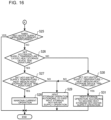
- Fig. 10 is a flow chart showing an example of the flow of a heat storage hot-water supply process that is performed by the hot-water supply apparatus according to Embodiment 1.
- the control command device 13 of the controller 10 reads out and acquires, from the set value storage area 121 of the data storage device 12, a set hot-water supply temperature set by a user.
- step S2 the control command device 13 reads out and acquires, from the set value storage area 121 of the data storage device 12, a boiling mode being set.
- the boiling mode is intended to determine which measured values measured by a plurality of temperature-measuring sensors 117 provided in the latent heat storage device 112 and the heat medium heat storage device 113 are referred to.
- This boiling mode may for example be set to be able to be updated by the user.
- step S3 the control command device 13 reads out and acquires, from the measured value storage area 122 of the data storage device 12, the internal temperature of the latent heat storage device 112 as measured by the sensor 117.
- step S4 the control command device 13 reads out and acquires, from the measured value storage area 122 of the data storage device 12, the internal temperature of the heat medium heat storage device 113 as measured by the sensor 117.
- step S5 the control command device 13 determines whether a hot-water supply request is present.
- the hot-water supply request is received by the control command device 13, for example, in a case in which the control command receiving device 119 receives a hot-water supply start command from the user, a case in which a hot-water supply start time set in advance in the set value storage area 121 of the data storage device 12 is reached, or other cases.
- This hot-water supply command may for example be set to be updated by the user.
- step S6 the heat medium circuit switching determining unit 131 of the control command device 13 makes a comparison between the set hot-water supply temperature acquired in step S1 and the internal temperature of the latent heat storage device 112 as acquired in step S3.
- the heat medium circuit switching determining unit 131 determines a connection of the first heat medium circuit switching device 115a and the second heat medium circuit switching device 115b so that the first hot-water supply operation shown in Fig. 8 is performed.
- step S7 the control command value calculating unit 132 of the control command device 13 calculates and generates control command values for the first heat medium circuit switching device 115a and the second heat medium circuit switching device 115b for the first hot-water supply operation to be performed.
- the control command device 13 supplies the control command values thus generated separately to each of the first and second heat medium circuit switching device 115a and 115b. This causes the first and second heat medium circuit switching devices 115a and 115b to switch from one connecting condition to another according to each separate control command value, so that the first hot-water supply operation is performed in the hot-water supply apparatus 1.
- the heat medium circuit switching determining unit 131 determines a connection of the first heat medium circuit switching device 115a and the second heat medium circuit switching device 115b so that the second hot-water supply operation shown in Fig. 9 is performed.
- the control command value calculating unit 132 calculates and generates control command values for the first heat medium circuit switching device 115a and the second heat medium circuit switching device 115b for the second hot-water supply operation to be performed.
- the control command device 13 supplies the control command values thus generated separately to each of the first and second heat medium circuit switching devices 115a and 115b. This causes the first and second heat medium circuit switching devices 115a and 115b to switch from one connecting condition to another according to each separate control command value, so that the second hot-water supply operation is performed in the hot-water supply apparatus 1.
- step S9 the heat medium circuit switching determining unit 131 makes a comparison between the set hot-water supply temperature acquired in step S1 and the internal temperature of the heat medium heat storage device 113 as acquired in step S4. In a case in which the set hot-water supply temperature is lower than the internal temperature of the heat medium heat storage device 113 as a result of the comparison (step S9: Yes), the heat medium circuit switching determining unit 131 makes a determination as to a connection of the first heat medium circuit switching device 115a and the second heat medium circuit switching device 115b in step S10 so that the current operation is maintained.
- the control command value calculating unit 132 calculates control command values for the first heat medium circuit switching device 115a and the second heat medium circuit switching device 115b based on a result of the determination made by the heat medium circuit switching determining unit 131. For example, in a case in which the current operation is the heat storage operation, the control command value calculating unit 132 continues the heat storage operation until heat is fully stored in the latent heat storage device 112 and the heat medium heat storage device 113, and after that, the control command value calculating unit 132 calculates and generates control command values for the first heat medium circuit switching device 115a and the second heat medium circuit switching device 115b for the heat storage operation to be stopped.
- the control command value calculating unit 132 calculates and generates control command values for the first heat medium circuit switching device 115a and the second heat medium circuit switching device 115b for the stopped state to be continued.
- the control command device 13 supplies the control command values thus generated separately to each of the first and second heat medium circuit switching devices 115a and 115b.
- the heat medium circuit switching determining unit 131 determines a connection of the first heat medium circuit switching device 115a and the second heat medium circuit switching device 115b so that the heat storage operation shown in Fig. 7 is performed. Then, in step S11, the control command value calculating unit 132 calculates and generates control command values for the first heat medium circuit switching device 115a and the second heat medium circuit switching device 115b for the heat storage operation to be performed. The control command device 13 supplies the control command values thus generated separately to each of the first and second heat medium circuit switching devices 115a and 115b. This causes the first and second heat medium circuit switching devices 115a and 115b to switch from one connecting condition to another according to each separate control command value, so that the heat storage operation is performed in the hot-water supply apparatus 1.
- the hot-water supply apparatus 1 is configured such that a heat medium flowing out from the lower portion of the heat medium heat storage device 113 with thermal stratification formed therein is heated by the heat pump device 111.
- the heat medium stored in the heat medium heat storage device 113 has thermal stratification formed therein, whereby a heat medium kept at a low temperature flows out from the heat medium heat storage device 113 and heated by the heat pump device 111.
- This makes it possible to improve energy efficiency in heating by the heat pump device 111 during the heat storage operation. Further, in this case, it is not necessary to cause a decrease in storage of heat per unit time in a heat storage tank. This makes it possible to keep the storage of heat per unit time high.
- a hot-water supply apparatus 1 according to Embodiment 2 differs from Embodiment 1 in that the latent heat storage device 112 and the heat medium heat storage device 113 are connected in parallel.
- Components of Embodiment 2 that are shared in common with Embodiment 1 are given identical reference signs, and a detailed description of such components is omitted.
- the hot-water supply apparatus 1 according to Embodiment 2 is similar in functional configuration to Embodiment 1 shown in Fig. 1 .
- Fig. 11 is a schematic view showing an example of a circuit configuration of the hot-water supply apparatus according to Embodiment 2. The following describes a relation of connection between one component of the hot-water supply apparatus 1 and another.
- the heat medium circuit switching device 115 includes first to eighth heat medium circuit switching devices 115a to 115h.
- the first to eighth heat medium circuit switching devices 115a to 115h are for example three-way valves each having three connecting ports.
- the first heat medium circuit switching device 115a has connecting ports to each of which the pipe in the lower portion of the latent heat storage device 112, the fifth heat medium circuit switching device 115e, and the seventh heat medium circuit switching device 115g are connected separately.
- the second heat medium circuit switching device 115b has connecting ports to each of which the pipe in the upper portion of the latent heat storage device 112, the fourth heat medium circuit switching device 115d, and the eighth heat medium circuit switching device 115h are connected separately.
- the third heat medium circuit switching device 115c has connecting ports to each of which the tap water supply source 2, one of the pipes in the lower portion of the heat medium heat storage device 113, and the fifth heat medium circuit switching device 115e are connected separately.
- the fourth heat medium circuit switching device 115d has connecting ports to each of which the hot-water demand side 3, one of the pipes in the upper portion of the heat medium heat storage device 113, and the second heat medium circuit switching device 115b are connected separately.
- the fifth heat medium circuit switching device 115e has connecting ports to each of which the first heat medium circuit switching device 115a, the third heat medium circuit switching device 115c, and the sixth heat medium circuit switching device 115f are connected separately.
- the sixth heat medium circuit switching device 115f has connecting ports to each of which the other of the pipes in the lower portion of the heat medium heat storage device 113, the fifth heat medium circuit switching device 115e, and the seventh heat medium circuit switching device 115g are connected separately.
- the seventh heat medium circuit switching device 115g has connecting ports to each of which the suction side of the pump 116, the first heat medium circuit switching device 115a, and the sixth heat medium circuit switching device 115f are connected separately.
- the eighth heat medium circuit switching device 115h has connecting ports to each of which the heat pump device 111, the other of the pipes in the upper portion of the heat medium heat storage device 113, and the second heat medium circuit switching device 115b are connected separately.
- Such a connection between one component and another allows the heat pump device 111 to be connected directly to both the latent heat storage device 112 and the heat medium heat storage device 113 and to supply a heated heat medium to each storage device.
- This also allows the tap water supply source 2 to be connected directly to both the latent heat storage device 112 and the heat medium heat storage device 113 and to supply a heat medium to each storage device.
- Actions of the hot-water supply apparatus 1 thus configured are described.
- the following describes the flow of a heat medium that circulates through the heat medium circuit during a heat storage operation and a hot-water supply operation and a heat storage hot-water supply process.
- the hot-water supply apparatus 1 according to Embodiment 2 can perform a first heat storage hot-water supply operation, a second heat storage hot-water supply operation, and a third hot-water supply operation. Further, in a case in which the storage of heat in either of the latent heat storage device 112 and the heat medium heat storage device 113 decreases, the hot-water supply apparatus 1 according to Embodiment 2 can perform a hot-water supply operation through the use of the other heat storage device. Furthermore, while continuing a hot-water supply operation through the use of one of the heat storage devices, the hot-water supply apparatus 1 can store heat in the other of the heat storage devices.
- a first heat storage hot-water supply operation that is performed by the hot-water supply apparatus 1 is described.
- the first heat storage hot-water supply operation is intended to perform a heat storage operation of heating a low-temperature heat medium with the heat pump device 111 and storing, in the heat medium heat storage device 113, the heat medium thus heated. Further, the first heat storage hot-water supply operation is intended to perform a hot-water supply operation of, through the use of heat stored in the latent heat storage device 112, supplying a heat medium at a set hot-water supply temperature to the hot-water demand side 3.
- Fig. 12 is a schematic view for explaining the flow of a heat medium during the first heat storage hot-water supply operation.
- the thick solid arrows indicate the flow of the heat medium during the heat storage operation.
- the thick dashed arrows indicate the flow of the heat medium during the hot-water supply operation.
- control command device 13 of the controller 10 supplies a control command value to each of the heat medium circuit switching devices 115 so that the connecting ports of each of the heat medium circuit switching devices 115 are brought into a state shown in Fig. 12 .
- the first heat medium circuit switching device 115a is switched so that the pipe in the lower portion of the latent heat storage device 112 and the fifth heat medium circuit switching device 115e become connected.
- the second heat medium circuit switching device 115b is switched so that the pipe in the upper portion of the latent heat storage device 112 and the fourth heat medium circuit switching device 115d become connected.
- the third heat medium circuit switching device 115c is switched so that the tap water supply source 2 and the fifth heat medium circuit switching device 115e become connected.
- the fourth heat medium circuit switching device 115d is switched so that the second heat medium circuit switching device 115b and the hot-water demand side 3 become connected.
- the fifth heat medium circuit switching device 115e is switched so that the first heat medium circuit switching device 115a and the third heat medium circuit switching device 115c become connected.
- the sixth heat medium circuit switching device 115f is switched so that one of the pipes in the lower portion of the heat medium heat storage device 113 and the seventh heat medium circuit switching device 115g become connected.
- the seventh heat medium circuit switching device 115g is switched so that the sixth heat medium circuit switching device 115f and the suction side of the pump 116 become connected.
- the eighth heat medium circuit switching device 115h is switched so that the heat pump device 111 and one of the pipes in the upper portion of the heat medium heat storage device 113 become connected.
- control command device 13 supplies a control command value to the pump 116 so that the pump 116 is driven.
- the pump 116 is driven based on the control command value, the heat medium stored in the lower portion of the heat medium heat storage device 113 flows out as shown in Fig. 12 .
- the heat medium stored in the lower portion of the heat medium heat storage device 113 always has thermal stratification formed therein, so that the heat medium flowing out from the lower portion of the heat medium heat storage device 113 is always in a low-temperature state.
- the low-temperature heat medium flowing out from the heat medium heat storage device 113 is suctioned into the suction side of the pump 116 via the sixth heat medium circuit switching device 115f and the seventh heat medium circuit switching device 115g, pressurized, and sent out.
- the heat medium sent out from the pump 116 is heated by the heat pump device 111 and flows out from the heat pump device 111.
- the high-temperature heat medium flowing out from the heat pump device 111 flows into the heat medium heat storage device 113 via the eighth heat medium circuit switching device 115h and is stored.
- the heat medium from the tap water supply source 2 flows into the lower portion of the latent heat storage device 112 via the third heat medium circuit switching device 115c, the fifth heat medium circuit switching device 115e, and the first heat medium circuit switching device 115a.
- the heat medium flowing into the latent heat storage device 112 is heated by the latent heat storage material rejecting heat and flows out from the latent heat storage device 112.
- the heat medium flowing out from the latent heat storage device 112 is supplied to the hot-water demand side 3 via the second heat medium circuit switching device 115b and the fourth heat medium circuit switching device 115d.
- both the heat storage operation, which involves the use of the heat medium heat storage device 113, and the hot-water supply operation, which involves the use of the latent heat storage device 112, can be simultaneously performed.
- the first heat storage hot-water supply operation is performed in a case in which sufficient storage of heat is present in the latent heat storage device 112 but sufficient storage of heat is not present in the heat medium heat storage device 113.
- a second heat storage hot-water supply operation that is performed by the hot-water supply apparatus 1 is described.
- the second heat storage hot-water supply operation is intended to perform a heat storage operation of heating a low-temperature heat medium with the heat pump device 111 and storing, in the latent heat storage device 112, the heat medium thus heated.
- the second heat storage hot-water supply operation is intended to perform a hot-water supply operation of, through the use of heat stored in the heat medium heat storage device 113, supplying a heat medium at a set hot-water supply temperature to the hot-water demand side 3.
- Fig. 13 is a schematic view for explaining the flow of the heat medium during the second heat storage hot-water supply operation.
- the thick solid arrows indicate the flow of the heat medium during the heat storage operation.
- the thick dashed arrows indicate the flow of the heat medium during the hot-water supply operation.
- control command device 13 supplies a control command value to each of the heat medium circuit switching devices 115 so that the connecting ports of each of the heat medium circuit switching devices 115 are brought into a state shown in Fig. 13 .
- the first heat medium circuit switching device 115a is switched so that the pipe in the lower portion of the latent heat storage device 112 and the seventh heat medium circuit switching device 115g become connected.
- the second heat medium circuit switching device 115b is switched so that the pipe in the upper portion of the latent heat storage device 112 and the eighth heat medium circuit switching device 115h become connected.
- the third heat medium circuit switching device 115c is switched so that the tap water supply source 2 and one of the pipes in the lower portion of the heat medium heat storage device 113 become connected.
- the fourth heat medium circuit switching device 115d is switched so that one of the pipes in the upper portion of the heat medium heat storage device 113 and the hot-water demand side 3 become connected.
- the fifth heat medium circuit switching device 115e and the sixth heat medium circuit switching device 115f are not used in the second heat storage hot-water supply operation.
- the seventh heat medium circuit switching device 115g is switched so that the first heat medium circuit switching device 115a and the suction side of the pump 116 become connected.
- the eighth heat medium circuit switching device 115h is switched so that the heat pump device 111 and the second heat medium circuit switching device 115b become connected.
- control command device 13 supplies a control command value to the pump 116 so that the pump 116 is driven.
- the heat medium flows out from the latent heat storage device 112 as shown in Fig. 13 .
- the heat medium flowing out from the latent heat storage device 112 is suctioned into the suction side of the pump 116 via the first heat medium circuit switching device 115a and the seventh heat medium circuit switching device 115g, pressurized, and sent out.
- the heat medium sent out from the pump 116 is heated by the heat pump device 111 and flows out from the heat pump device 111.
- the high-temperature heat medium flowing out from the heat pump device 111 flows into the latent heat storage device 112 via the eighth heat medium circuit switching device 115h and the second heat medium circuit switching device 115b.
- the high-temperature heat medium flowing into the latent heat storage device 112 heats the latent heat storage material and flows out from the latent heat storage device 112.
- the heat medium from the tap water supply source 2 flows into the lower portion of the heat medium heat storage device 113 via the third heat medium circuit switching device 115c.
- the heat medium stored in the upper portion of the heat medium heat storage device 113 flows out.
- the heat medium stored in the heat medium heat storage device 113 always has thermal stratification formed therein, so that the heat medium flowing out from the upper portion of the heat medium heat storage device 113 is always in a high-temperature state.
- the heat medium flowing out from the heat medium heat storage device 113 is supplied to the hot-water demand side 3 via the fourth heat medium circuit switching device 115d.
- both the heat storage operation and the hot-water supply operation can be simultaneously performed, as in the case of the first heat storage hot-water supply operation.
- the second heat storage hot-water supply operation is performed in a case in which sufficient storage of heat is not present in the latent heat storage device 112 but sufficient storage of heat is present in the heat medium heat storage device 113.
- the third hot-water supply operation is an operation that is performed with the heat pump device 111 in a case in which heat is not sufficiently stored in the latent heat storage device 112 or the heat medium heat storage device 113.
- Fig. 14 is a schematic view for explaining the flow of the heat medium during the third hot-water supply operation.
- the thick arrows indicate the flow of the heat medium.
- the first heat medium circuit switching device 115a is switched so that the fifth heat medium circuit switching device 115e and the seventh heat medium circuit switching device 115g become connected.
- the second heat medium circuit switching device 115b is switched so that the fourth heat medium circuit switching device 115d and the eighth heat medium circuit switching device 115h become connected.
- the third heat medium circuit switching device 115c is switched so that the tap water supply source 2 and fifth heat medium circuit switching device 115e become connected.
- the fourth heat medium circuit switching device 115d is switched so that the second heat medium circuit switching device 115b and the hot-water demand side 3 become connected.
- the fifth heat medium circuit switching device 115e is switched so that the first heat medium circuit switching device 115a and the third heat medium circuit switching device 115c become connected.
- the sixth heat medium circuit switching device 115f is not used in the third hot-water supply operation.
- the seventh heat medium circuit switching device 115g is switched so that the first heat medium circuit switching device 115a and the suction side of the pump 116 become connected.
- the eighth heat medium circuit switching device 115h is switched so that the heat pump device 111 and the second heat medium circuit switching device 115b become connected.
- control command device 13 supplies a control command value to the pump 116 so that the pump 116 is driven.
- the pump 116 is driven based on the control command value, the low-temperature heat medium supplied from the tap water supply source 2 is suctioned into the suction side of the pump 116 via the third heat medium circuit switching device 115c, the fifth heat medium circuit switching device 115e, the first heat medium circuit switching device 115a, and the seventh heat medium circuit switching device 115g, pressurized, and sent out as shown in Fig. 14 .
- the heat medium sent out from the pump 116 is heated by the heat pump device 111 and flows out from the heat pump device 111.
- the high-temperature heat medium flowing out from the heat pump device 111 is supplied to the hot-water demand side 3 via the eighth heat medium circuit switching device 115h, the second heat medium circuit switching device 115b, and the fourth heat medium circuit switching device 115d.
- the heat medium supplied from the tap water supply source 2 is heated by the heat pump device 111, and the heat medium thus heated is supplied to the hot-water demand side 3. Therefore, even in a case in which heat is not sufficiently stored in the latent heat storage device 112 or the heat medium heat storage device 113, the heat medium is heated by the heat pump device 111, so that the hot-water supply apparatus 1 can continue the hot-water supply operation. In this case, however, the aforementioned heat storage operation cannot be executed in the third hot-water supply operation, as the heat pump device 111 is used for the hot-water supply operation.
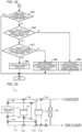
- Figs. 15 and 16 are flow charts showing an example of a heat storage hot-water supply process that is performed by the hot-water supply apparatus according to Embodiment 2. Steps of the process shown in Figs. 15 and 16 that are shared common with Embodiment 1 are given identical reference signs, and a detailed description of such steps is omitted. In the flow charts shown in Figs. 15 and 16 , symbol A indicates that the process shifts to the corresponding symbol. The processes in steps S1 to S4, which are shared in common with Embodiment 1, are not described here.
- step S5 the control command device 13 of the controller 10 determines whether a hot-water supply request is present. In a case in which the control command device 13 receives the hot-water supply request (step S5: Yes), the process shifts to step S6. On the other hand, in a case in which the control command device 13 does not receive the hot-water supply request in step S5 (step S5: No), the process shifts to step S25.
- step S6 the heat medium circuit switching determining unit 131 of the control command device 13 makes a comparison between the set hot-water supply temperature acquired in step S1 and the internal temperature of the latent heat storage device 112 as acquired in step S3.
- the heat medium circuit switching determining unit 131 determines a connection of each heat medium circuit switching device 115 so that the first heat storage hot-water supply operation shown in Fig. 12 is performed.
- step S21 the control command value calculating unit 132 of the control command device 13 calculates and generates control command values for each separate heat medium circuit switching device 115 for the first heat storage hot-water supply operation to be performed.
- the control command device 13 supplies the control command values thus generated separately to each heat medium circuit switching device 115. This causes the hot-water supply apparatus 1 to perform a hot-water supply operation according to the first heat storage hot-water supply operation.
- step S6 the process shifts to step S22.
- step S22 the heat medium circuit switching determining unit 131 makes a comparison between the set hot-water supply temperature acquired in step S1 and the internal temperature of the heat medium heat storage device 113 as acquired in step S4.
- the heat medium circuit switching determining unit 131 determines a connection of each heat medium circuit switching device 115 so that the second heat storage hot-water supply operation shown in Fig. 13 is performed.
- step S23 the control command value calculating unit 132 calculates and generates control command values for each separate heat medium circuit switching device 115.
- the control command device 13 supplies the control command values thus generated separately to each heat medium circuit switching device 115. This causes the hot-water supply apparatus 1 to perform a hot-water supply operation according to the second heat storage hot-water supply operation.
- the heat medium circuit switching determining unit 131 determines a connection of each heat medium circuit switching device 115 so that the third hot-water supply operation shown in Fig. 14 is performed. Then, in step S24, the control command value calculating unit 132 calculates and generates control command values for each separate heat medium circuit switching device 115. The control command device 13 supplies the control command values thus generated separately to each heat medium circuit switching device 115. This causes the hot-water supply apparatus 1 to perform the third hot-water supply operation.
- step S25 the control command device 13 determines whether the current hot-water supply operation is a hot-water supply operation during which hot water is supplied directly from the heat pump device 111, that is, the third hot-water supply operation. In a case in which the third hot-water supply operation is currently performed (step S25: Yes), the heat storage operation is not performed, and the series of processes ends. On the other hand, in a case in which he third hot-water supply operation is not currently performed (step S25: No), the process shifts to step S26.
- step S26 the heat medium circuit switching determining unit 131 makes a comparison between the set hot-water supply temperature and the internal temperature of the latent heat storage device 112. In a case in which the set hot-water supply temperature is lower than the internal temperature of the latent heat storage device 112 as a result of the comparison (step S26: Yes), the process shifts to step S27. In step S27, the heat medium circuit switching determining unit 131 makes a comparison between the set hot-water supply temperature and the internal temperature of the heat medium heat storage device 113.
- the heat medium circuit switching determining unit 131 makes a determination as to a connection of each heat medium circuit switching device 115 in step S28 so that the current operation is maintained.
- the control command value calculating unit 132 calculates control command values for each separate heat medium circuit switching device 115 based on a result of the determination made by the heat medium circuit switching determining unit 131.
- the control command value calculating unit 132 continues the heat storage operation until heat is fully stored in the latent heat storage device 112 and the heat medium heat storage device 113, and after that, the control command value calculating unit 132 calculates and generates control command values for each separate heat medium circuit switching device 115 for the heat storage operation to be stopped. Further, in a case in which the current operational state is a stopped state, the control command value calculating unit 132 calculates and generates control command values for each separate heat medium circuit switching device 115 for the stopped state to be continued. The control command device 13 supplies the control command values thus generated separately to each heat medium circuit switching device 115.
- the heat medium circuit switching determining unit 131 determines a connection of each heat medium circuit switching device 115 so that the first heat storage hot-water supply operation shown in Fig. 12 is performed.
- step S29 the control command value calculating unit 132 calculates and generates control command values for each separate heat medium circuit switching device 115 for the first heat storage hot-water supply operation to be performed.
- the control command device 13 supplies the control command values thus generated separately to each heat medium circuit switching device 115. This causes the hot-water supply apparatus 1 to perform a heat storage operation according to the first heat storage hot-water supply operation.
- step S26 the process shifts to step S30.
- the heat medium circuit switching determining unit 131 makes a comparison between the set hot-water supply temperature and the internal temperature of the heat medium heat storage device 113.
- step S30 In a case in which the set hot-water supply temperature is higher than or equal to the internal temperature of the heat medium heat storage device 113 as a result of the comparison (step S30: No), the process shifts to step S29, in which a heat storage operation according to the first heat storage hot-water supply operation is performed.
- step S30 determines a connection of each heat medium circuit switching device 115 so that the second heat storage hot-water supply operation shown in Fig. 13 is performed.
- step S31 the control command value calculating unit 132 calculates and generates control command values for each separate heat medium circuit switching device 115.
- the control command device 13 supplies the control command values thus generated separately to each heat medium circuit switching device 115.
- the hot-water supply apparatus 1 according to Embodiment 2 can bring about effects that are similar to those of Embodiment 1. Further, in the hot-water supply apparatus 1, the latent heat storage device 112 and the heat medium heat storage device 113 are connected in parallel. As a result of this, in a case in which the storage of heat in either of the two heat storage devices decreases, a heat storage operation on one storage device and a hot-water supply operation involving the use of the other heat storage device can be simultaneously performed.
- a hot-water supply apparatus 1 according to Embodiment 3 differs from Embodiments 1 and 2 in that the latent heat storage device 112 and the heat medium heat storage device 113 are connected in series or in parallel.
- Components of Embodiment 3 that are shared in common with Embodiments 1 and 2 are given identical reference signs, and a detailed description of such components is omitted.
- the hot-water supply apparatus 1 according to Embodiment 3 is similar in functional configuration to Embodiments 1 and 2 shown in Fig. 1 .
- Fig. 17 is a schematic view showing an example of a circuit configuration of the hot-water supply apparatus according to Embodiment 3. The following describes a relation of connection between one component of the hot-water supply apparatus 1 and another.
- the heat medium circuit switching device 115 includes first to tenth heat medium circuit switching devices 115a to 115j.
- the first to tenth heat medium circuit switching devices 115a to 115j are for example three-way valves each having three connecting ports.
- the first heat medium circuit switching device 115a has connecting ports to each of which the fifth heat medium circuit switching device 115e, the seventh heat medium circuit switching device 115g, and the ninth heat medium circuit switching device 115i are connected separately.
- the second heat medium circuit switching device 115b has connecting ports to each of which the pipe in the upper portion of the latent heat storage device 112, the fourth heat medium circuit switching device 115d, and the eighth heat medium circuit switching device 115h are connected separately.
- the third heat medium circuit switching device 115c has connecting ports to each of which the tap water supply source 2, one of the pipes in the lower portion of the heat medium heat storage device 113, and the fifth heat medium circuit switching device 115e are connected separately.
- the fourth heat medium circuit switching device 115d has connecting ports to each of which the hot-water demand side 3, one of the pipes in the upper portion of the heat medium heat storage device 113, and the second heat medium circuit switching device 115b are connected separately.
- the fifth heat medium circuit switching device 115e has connecting ports to each of which the first heat medium circuit switching device 115a, the third heat medium circuit switching device 115c, and the sixth heat medium circuit switching device 115f are connected separately.
- the sixth heat medium circuit switching device 115f has connecting ports to each of which the other of the pipes in the lower portion of the heat medium heat storage device 113, the fifth heat medium circuit switching device 115e, and the seventh heat medium circuit switching device 115g are connected separately.
- the seventh heat medium circuit switching device 115g has connecting ports to each of which the suction side of the pump 116, the first heat medium circuit switching device 115a, and the sixth heat medium circuit switching device 115f are connected separately.
- the eighth heat medium circuit switching device 115h has connecting ports to each of which the heat pump device 111, the second heat medium circuit switching device 115b, and the tenth heat medium circuit switching device 115j are connected separately.
- the ninth heat medium circuit switching device 115i has connecting ports to each of which the pipe in the lower portion of the latent heat storage device 112, the first heat medium circuit switching device 115a, and the tenth heat medium circuit switching device 115j are connected separately.
- the tenth heat medium circuit switching device 115j has connecting ports to each of which the other of the pipes in the upper portion of the heat medium heat storage device 113, the eighth heat medium circuit switching device 115h and the ninth heat medium circuit switching device 115i are connected separately.
- the hot-water supply apparatus 1 can perform a first heat storage hot-water supply operation, a second heat storage hot-water supply operation, and a third hot-water supply operation.
- a third heat storage hot-water supply operation that is performed by the hot-water supply apparatus 1 is described.
- the third heat storage hot-water supply operation is intended to perform a heat storage operation of heating a low-temperature heat medium with the heat pump device 111 and storing, in the heat medium heat storage device 113, the heat medium thus heated.
- the third heat storage hot-water supply operation is intended to perform a hot-water supply operation of, through the use of heat stored in the latent heat storage device 112, supplying a heat medium at a set hot-water supply temperature to the hot-water demand side 3.
- Fig. 18 is a schematic view for explaining the flow of a heat medium during the third heat storage hot-water supply operation.
- the thick solid arrows indicate the flow of the heat medium during the heat storage operation.
- the thick dashed arrows indicate the flow of the heat medium during the hot-water supply operation.
- the first heat medium circuit switching device 115a is switched so that the fifth heat medium circuit switching device 115e and the ninth heat medium circuit switching device 115i become connected.
- the second heat medium circuit switching device 115b is switched so that the pipe in the upper portion of the latent heat storage device 112 and the fourth heat medium circuit switching device 115d become connected.
- the third heat medium circuit switching device 115c is switched so that the tap water supply source 2 and the fifth heat medium circuit switching device 115e become connected.
- the fourth heat medium circuit switching device 115d is switched so that the second heat medium circuit switching device 115b and the hot-water demand side 3 become connected.
- the fifth heat medium circuit switching device 115e is switched so that the first heat medium circuit switching device 115a and the third heat medium circuit switching device 115c become connected.
- the sixth heat medium circuit switching device 115f is switched so that one of the pipes in the lower portion of the heat medium heat storage device 113 and the seventh heat medium circuit switching device 115g become connected.
- the seventh heat medium circuit switching device 115g is switched so that the sixth heat medium circuit switching device 115f and the suction side of the pump 116 become connected.
- the eighth heat medium circuit switching device 115h is switched so that the heat pump device 111 and the tenth heat medium circuit switching device 115j become connected.
- the ninth heat medium circuit switching device 115i is switched so that the pipe in the lower portion of the latent heat storage device 112 and the first heat medium circuit switching device 115a become connected.
- the tenth heat medium circuit switching device 115j is switched so that one of the pipes in the upper portion of the heat medium heat storage device 113 and the eighth heat medium circuit switching device 115h become connected.
- control command device 13 supplies a control command value to the pump 116 so that the pump 116 is driven.
- the pump 116 is driven based on the control command value, the heat medium stored in the lower portion of the heat medium heat storage device 113 flows out as shown in Fig. 18 .
- the heat medium stored in the lower portion of the heat medium heat storage device 113 always has thermal stratification formed therein, so that the heat medium flowing out from the lower portion of the heat medium heat storage device 113 is always in a low-temperature state.
- the low-temperature heat medium flowing out from the heat medium heat storage device 113 is suctioned into the suction side of the pump 116 via the sixth heat medium circuit switching device 115f and the seventh heat medium circuit switching device 115g, pressurized, and sent out.
- the heat medium sent out from the pump 116 is heated by the heat pump device 111 and flows out from the heat pump device 111.
- the high-temperature heat medium flowing out from the heat pump device 111 flows into the heat medium heat storage device 113 via the eighth heat medium circuit switching device 115h and the tenth heat medium circuit switching device 115j and is stored.
- the heat medium from the tap water supply source 2 flows into the lower portion of the latent heat storage device 112 via the third heat medium circuit switching device 115c, the fifth heat medium circuit switching device 115e, the first heat medium circuit switching device 115a, and the ninth heat medium circuit switching device 115i.
- the heat medium flowing into the latent heat storage device 112 is heated by the latent heat storage material rejecting heat and flows out from the latent heat storage device 112.
- the heat medium flowing out from the latent heat storage device 112 is supplied to the hot-water demand side 3 via the second heat medium circuit switching device 115b and the fourth heat medium circuit switching device 115d.
- both the heat storage operation and the hot-water supply operation can be simultaneously performed as in the case of the first heat storage hot-water supply operation of Embodiment 2. It should be noted that the third heat storage hot-water supply operation is performed in a case in which sufficient storage of heat is present in the latent heat storage device 112 but sufficient storage of heat is not present in the heat medium heat storage device 113.
- the fourth heat storage hot-water supply operation is intended to perform a heat storage operation of heating a low-temperature heat medium with the heat pump device 111, storing, in the latent heat storage device 112, the heat medium thus heated, and storing the high-temperature heat medium in the heat medium heat storage device 113. Further, the fourth heat storage hot-water supply operation is intended to perform a hot-water supply operation of, through the use of heat stored in the heat medium heat storage device 113, supplying a heat medium at a set hot-water supply temperature to the hot-water demand side 3.
- Fig. 19 is a schematic view for explaining the flow of the heat medium during the fourth heat storage hot-water supply operation.
- the thick solid arrows indicate the flow of the heat medium during the heat storage operation.
- the thick dashed arrows indicate the flow of the heat medium during the hot-water supply operation.
- the first heat medium circuit switching device 115a is switched so that the fifth heat medium circuit switching device 115e and the seventh heat medium circuit switching device 115g become connected.
- the second heat medium circuit switching device 115b is switched so that the pipe in the upper portion of the latent heat storage device 112 and the eighth heat medium circuit switching device 115h become connected.
- the third heat medium circuit switching device 115c is switched so that the tap water supply source 2 and one of the pipes in the lower portion of the heat medium heat storage device 113 become connected.
- the fourth heat medium circuit switching device 115d is switched so that one of the pipes in the upper portion of the heat medium heat storage device 113 and the hot-water demand side 3 become connected.
- the fifth heat medium circuit switching device 115e is switched so that the first heat medium circuit switching device 115a and the sixth heat medium circuit switching device 115f become connected.
- the sixth heat medium circuit switching device 115f is switched so that the other of the pipes in the lower portion of the heat medium heat storage device 113 and the fifth heat medium circuit switching device 115e become connected.
- the seventh heat medium circuit switching device 115g is switched so that the first heat medium circuit switching device 115a and the suction side of the pump 116 become connected.
- the eighth heat medium circuit switching device 115h is switched so that the heat pump device 111 and the second heat medium circuit switching device 115b become connected.
- the ninth heat medium circuit switching device 115i is switched so that the pipe in the lower portion of the latent heat storage device 112 and the tenth heat medium circuit switching device 115j become connected.
- the tenth heat medium circuit switching device 115j is switched so that the other of the pipes in the upper portion of the heat medium heat storage device 113 and the ninth heat medium circuit switching device 115i become connected.
- control command device 13 supplies a control command value to the pump 116 so that the pump 116 is driven.
- the pump 116 is driven based on the control command value, the heat medium stored in the lower portion of the heat medium heat storage device 113 flows out as shown in Fig. 19 .
- the heat medium stored in the lower portion of the heat medium heat storage device 113 always has thermal stratification formed therein, so that the heat medium flowing out from the lower portion of the heat medium heat storage device 113 is always in a low-temperature state.
- the low-temperature heat medium flowing out from the heat medium heat storage device 113 is suctioned into the suction side of the pump 116 via the sixth heat medium circuit switching device 115f, the fifth heat medium circuit switching device 115e, the first heat medium circuit switching device 115a, and the seventh heat medium circuit switching device 115g, pressurized, and sent out.
- the heat medium sent out from the pump 116 is heated by the heat pump device 111 and flows out from the heat pump device 111.
- the high-temperature heat medium flowing out from the heat pump device 111 flows into the latent heat storage device 112 via the eighth heat medium circuit switching device 115h and the second heat medium circuit switching device 115b.
- the high-temperature heat medium flowing into the latent heat storage device 112 heats the latent heat storage material and flows out from the latent heat storage device 112. Then, the heat medium flowing out from the latent heat storage device 112 flows into the heat medium heat storage device 113 via the ninth heat medium circuit switching device 115i and the tenth heat medium circuit switching device 115j and is stored.
- the heat medium from the tap water supply source 2 flows into the lower portion of the heat medium heat storage device 113 via the third heat medium circuit switching device 115c.
- the heat medium stored in the upper portion of the heat medium heat storage device 113 flows out.
- the heat medium stored in the heat medium heat storage device 113 always has thermal stratification formed therein, so that the heat medium flowing out from the upper portion of the heat medium heat storage device 113 is always in a high-temperature state.
- the heat medium flowing out from the heat medium heat storage device 113 is supplied to the hot-water demand side 3 via the fourth heat medium circuit switching device 115d.
- both the heat storage operation and the hot-water supply operation can be simultaneously performed, as in the case of the third heat storage hot-water supply operation. It should be noted that the fourth heat storage hot-water supply operation is performed in a case in which sufficient storage of heat is not present in the latent heat storage device 112 but sufficient storage of heat is present in the heat medium heat storage device 113.
- the fourth hot-water supply operation is an operation that is performed in a case in which heat is not sufficiently stored in the latent heat storage device 112 or the heat medium heat storage device 113.
- Fig. 20 is a schematic view for explaining the flow of the heat medium during the fourth hot-water supply operation.
- the thick arrows indicate the flow of the heat medium.
- the first heat medium circuit switching device 115a is switched so that the fifth heat medium circuit switching device 115e and the seventh heat medium circuit switching device 115g become connected.
- the second heat medium circuit switching device 115b is switched so that the fourth heat medium circuit switching device 115d and the eighth heat medium circuit switching device 115h become connected.
- the third heat medium circuit switching device 115c is switched so that the tap water supply source 2 and the fifth heat medium circuit switching device 115e become connected.
- the fourth heat medium circuit switching device 115d is switched so that the second heat medium circuit switching device 115b and the hot-water demand side 3 become connected.
- the fifth heat medium circuit switching device 115e is switched so that the first heat medium circuit switching device 115a and the third heat medium circuit switching device 115c become connected.
- the sixth heat medium circuit switching device 115f is not used in the third hot-water supply operation.
- the seventh heat medium circuit switching device 115g is switched so that the first heat medium circuit switching device 115a and the suction side of the pump 116 become connected.
- the eighth heat medium circuit switching device 115h is switched so that the heat pump device 111 and the second heat medium circuit switching device 115b become connected.
- the ninth heat medium circuit switching device 115i and the tenth heat medium circuit switching device 115j are not used in the third hot-water supply operation.
- control command device 13 supplies a control command value to the pump 116 so that the pump 116 is driven.
- the pump 116 is driven based on the control command value, the low-temperature heat medium supplied from the tap water supply source 2 is suctioned into the suction side of the pump 116 via the third heat medium circuit switching device 115c, the fifth heat medium circuit switching device 115e, the first heat medium circuit switching device 115a, and the seventh heat medium circuit switching device 115g, pressurized, and sent out as shown in Fig. 20 .
- the heat medium sent out from the pump 116 is heated by the heat pump device 111 and flows out from the heat pump device 111.
- the high-temperature heat medium flowing out from the heat pump device 111 is supplied to the hot-water demand side 3 via the eighth heat medium circuit switching device 115h, the second heat medium circuit switching device 115b, and the fourth heat medium circuit switching device 115d.
- the heat medium supplied from the tap water supply source 2 is heated by the heat pump device 111, and the heat medium thus heated is supplied to the hot-water demand side 3. Therefore, even in a case in which heat is not sufficiently stored in the latent heat storage device 112 or the heat medium heat storage device 113, the heat medium is heated by the heat pump device 111, so that the hot-water supply apparatus 1 can continue the hot-water supply operation. In this case, however, the aforementioned heat storage operation cannot be executed in the fourth hot-water supply operation, as the heat pump device 111 is used for the hot-water supply operation.
- Figs. 21 and 22 are flow charts showing an example of a heat storage hot-water supply process that is performed by the hot-water supply apparatus according to Embodiment 3. Steps of the process shown in Figs. 21 and 22 that are shared common with Embodiments 1 and 2 are given identical reference signs, and a detailed description of such steps is omitted. In the flow charts shown in Figs. 21 and 22 , symbol B indicates that the process shifts to the corresponding symbol. The processes in steps S1 to S4, which are shared in common with Embodiment 1, are not described here.
- step S5 the control command device 13 of the controller 10 determines whether a hot-water supply request is present. In a case in which the control command device 13 receives the hot-water supply request (step S5: Yes), the process shifts to step S6. On the other hand, in a case in which the control command device 13 does not receive the hot-water supply request in step S5 (step S5: No), the process shifts to step S45.
- step S6 the heat medium circuit switching determining unit 131 of the control command device 13 makes a comparison between the set hot-water supply temperature acquired in step S1 and the internal temperature of the latent heat storage device 112 as acquired in step S3.
- the heat medium circuit switching determining unit 131 determines a connection of each heat medium circuit switching device 115 so that the third heat storage hot-water supply operation shown in Fig. 18 is performed.
- step S41 the control command value calculating unit 132 of the control command device 13 calculates and generates control command values for each separate heat medium circuit switching device 115 for the third heat storage hot-water supply operation to be performed.
- the control command device 13 supplies the control command values thus generated separately to each heat medium circuit switching device 115. This causes the hot-water supply apparatus 1 to perform a hot-water supply operation according to the third heat storage hot-water supply operation.
- step S42 the heat medium circuit switching determining unit 131 makes a comparison between the set hot-water supply temperature acquired in step S1 and the internal temperature of the heat medium heat storage device 113 as acquired in step S4. In a case in which the set hot-water supply temperature is lower than the internal temperature of the heat medium heat storage device 113 as a result of the comparison (step S42: Yes), the heat medium circuit switching determining unit 131 determines a connection of each heat medium circuit switching device 115 so that the fourth heat storage hot-water supply operation shown in Fig. 19 is performed.
- step S43 the control command value calculating unit 132 calculates and generates control command values for each separate heat medium circuit switching device 115.
- the control command device 13 supplies the control command values thus generated separately to each heat medium circuit switching device 115. This causes the hot-water supply apparatus 1 to perform a hot-water supply operation according to the fourth heat storage hot-water supply operation.
- step S42 determines a connection of each heat medium circuit switching device 115 so that the fourth hot-water supply operation shown in Fig. 20 is performed.
- step S44 the control command value calculating unit 132 calculates and generates control command values for each separate heat medium circuit switching device 115.
- the control command device 13 supplies the control command values thus generated separately to each heat medium circuit switching device 115. This causes the hot-water supply apparatus 1 to perform the fourth hot-water supply operation.
- step S45 the control command device 13 determines whether the current hot-water supply operation is a hot-water supply operation during which hot water is supplied directly from the heat pump device 111, that is, the fourth hot-water supply operation. In a case in which the fourth hot-water supply operation is currently performed (step S45: Yes), the heat storage operation is not performed, and the series of processes ends. On the other hand, in a case in which the fourth hot-water supply operation is not currently performed (step S45: No), the process shifts to step S46.
- step S46 the heat medium circuit switching determining unit 131 makes a comparison between the set hot-water supply temperature and the internal temperature of the latent heat storage device 112. In a case in which the set hot-water supply temperature is lower than the internal temperature of the latent heat storage device 112 as a result of the comparison (step S46: Yes), the process shifts to step S47.
- step S47 the heat medium circuit switching determining unit 131 makes a comparison between the set hot-water supply temperature and the internal temperature of the heat medium heat storage device 113.
- the heat medium circuit switching determining unit 131 makes a determination as to a connection of each heat medium circuit switching device 115 in step S48 so that the current operation is maintained.
- the control command value calculating unit 132 calculates control command values for each separate heat medium circuit switching device 115 based on a result of the determination made by the heat medium circuit switching determining unit 131.
- the control command value calculating unit 132 continues the heat storage operation until heat is fully stored in the latent heat storage device 112 and the heat medium heat storage device 113, and after that, the control command value calculating unit 132 calculates and generates control command values for each separate heat medium circuit switching device 115 for the heat storage operation to be stopped. Further, in a case in which the current operational state is a stopped state, the control command value calculating unit 132 calculates and generates control command values for each separate heat medium circuit switching device 115 for the stopped state to be continued. The control command device 13 supplies the control command values thus generated separately to each heat medium circuit switching device 115.
- the heat medium circuit switching determining unit 131 determines a connection of each heat medium circuit switching device 115 so that the third heat storage hot-water supply operation shown in Fig. 18 is performed. Then, in step S49, the control command value calculating unit 132 calculates and generates control command values for each separate heat medium circuit switching device 115 for the third heat storage hot-water supply operation to be performed. The control command device 13 supplies the control command values thus generated separately to each heat medium circuit switching device 115. This causes the hot-water supply apparatus 1 to perform a heat storage operation according to the third heat storage hot-water supply operation.
- step S50 the heat medium circuit switching determining unit 131 determines a connection of each heat medium circuit switching device 115 so that the fourth heat storage hot-water supply operation shown in Fig. 19 is performed. Then, the control command value calculating unit 132 calculates and generates control command values for each separate heat medium circuit switching device 115. The control command device 13 supplies the control command values thus generated separately to each heat medium circuit switching device 115. This causes the hot-water supply apparatus 1 to perform a heat storage operation according to the fourth heat storage hot-water supply operation.
- Fig. 23 is a schematic view showing an example of a circuit configuration of a modification of a hot-water supply apparatus according to Embodiment 3.
- the hot-water supply apparatus 1 employs an indirect hot-water supply system in which hot water is supplied to the hot-water demand side 3 by rejecting heat stored in the heat source unit 11 to a second heat medium supplied from the tap water supply source 2.
- the hot-water supply apparatus 1 further includes a heat exchanger 140 and a hot-water supply pump in addition to the components shown in Fig. 17 .
- the heat exchanger 140 is disposed between the third heat medium circuit switching device 115c and the fourth heat medium circuit switching device 115d.
- the hot-water supply pump 141 is disposed between the heat exchanger 140 and the third heat medium circuit switching device 115c.
- the heat exchanger 140 exchanges heat between the heat medium flowing out from the heat medium heat storage device 113 and the second heat medium supplied from the tap water supply source 2.
- the hot-water supply pump 141 is configured to cause the heat medium to circulate from the heat pump device 111, the latent heat storage device 112, or the heat medium heat storage device 113 to the heat exchanger 140 and driven by a motor (not illustrated).
- each heat medium circuit switching device 115 is controlled in the hot-water supply apparatus 1 as in the case of the hot-water supply apparatus 1 shown in Fig. 17 .
- the hot-water supply pump 141 is driven, the heat medium circulating through the heat medium circuit flows into the heat exchanger 140.
- the heat medium flowing into the heat exchanger 140 exchanges heat in the heat exchanger 140 with the second heat medium supplied from the tap water supply source 2 and rejects heat to the second heat medium.
- the second heat medium heated by exchanging heat with the heat medium is supplied to the hot-water demand side 3.
- the third heat storage hot-water supply operation, the fourth heat storage hot-water supply operation, and the fourth hot-water supply operation can be performed as in the case of the hot-water supply apparatus 1 shown in Fig. 17 .
- the hot-water supply apparatus 1 can bring about effects that are similar to those of Embodiments 1 and 2. Further, in the hot-water supply apparatus 1, each heat medium circuit switching device 115 is switched, whereby the latent heat storage device 112 and the heat medium heat storage device 113 are connected in series or in parallel. As a result of this, in a case in which the storage of heat in either of the two heat storage devices decreases, a heat storage operation on one storage device and a hot-water supply operation involving the use of the other heat storage device can be simultaneously performed.
- Embodiments 1 to 3 of the present disclosure the present disclosure is not limited to the aforementioned Embodiments 1 to 3 but can be modified or applied without departing from the scope of the present disclosure.
Landscapes
- Engineering & Computer Science (AREA)
- Physics & Mathematics (AREA)
- Thermal Sciences (AREA)
- Mechanical Engineering (AREA)
- General Engineering & Computer Science (AREA)
- Chemical & Material Sciences (AREA)
- Combustion & Propulsion (AREA)
- Heat-Pump Type And Storage Water Heaters (AREA)
- Instantaneous Water Boilers, Portable Hot-Water Supply Apparatuses, And Control Of Portable Hot-Water Supply Apparatuses (AREA)
Abstract
Description
- The present disclosure relates to a hot-water supply apparatus including a heat storage tank configured to store heat produced by a heat source.
- There has conventionally been known a hot-water supply apparatus constituted by a heat pump unit and a tank unit that are separate from each other. Such a hot-water supply apparatus is configured such that the heat pump unit and the tank unit are connected by a refrigerant pipe or a heat medium pipe, a power wire, and a communication wire or other wires and integrally operate.
- There has recently been proposed a hot-water supply apparatus configured such that for the purpose of reducing the size of a tank unit, a latent heat storage material that is higher in storage of heat per unit volume than water is used as a heat storage material in a heat storage tank (see, for example, Patent Literature 1). In the hot-water supply apparatus described in
Patent Literature 1, the latent heat storage material is used as the heat storage material in the heat storage tank, and because of the properties of the latent heat storage material, the temperature of hot water serving as a heat medium that flows out from the heat storage tank to a heating unit does not become lower than the temperature of the latent heat storage material. Therefore, accumulation of heat in the heat storage tank proceeds, and the temperature of hot water that flows out from the heat storage tank to the heating unit increases as the temperature of the heat medium in the heat storage tank increases, with the result that there is undesirably a decrease in energy efficiency. To address this problem, there has been proposed a technique for maintaining high energy efficiency by reducing the heating temperature or the flow rate of the heat medium according to the state of accumulation of heat in the heat storage material (see, for example, Patent Literature 2). -
- Patent Literature 1:
Japanese Unexamined Patent Application Publication No. 2009-085565 - Patent Literature 2:
Japanese Unexamined Patent Application Publication No. 2015-175582 - However, in
Patent Literature 2, the heating temperature and flow rate of the heat medium are controlled according to the state of accumulation of heat in the heat storage tank, and the temperature and flow rate of the heat medium are reduced as the temperature of the heat medium increases. Therefore, there has undesirably been a decrease in storage of heat per unit time in the heat storage tank. - The present disclosure was made in view of the problems in the conventional technologies and has as an object to provide a hot-water supply apparatus configured to improve energy efficiency during a heat storage operation without causing a decrease in storage of heat per unit time in a heat storage tank.
- A hot-water supply apparatus according to an embodiment of the present disclosure is a hot-water supply apparatus for performing a heat storage operation of storing heat of a heat medium and a hot-water supply operation of supplying hot water to a hot-water demand side through use of the heat of the heat medium. The hot-water supply apparatus includes a heat medium circuit through which the heat medium circulates, a latent heat storage device having a latent heat storage material, the latent heat storage device being configured to store heat and reject heat through transfer of heat between the latent heat storage material and the heat medium, a heat medium heat storage device in which the heat medium is stored so that thermal stratification is formed, and a heating device configured to heat the heat medium. The heating device heats at least the heat medium flowing out from a lower portion of the heat medium heat storage device.
- According to the embodiment of the present disclosure, the heat medium flowing out from the lower portion of the heat medium heat storage device with the thermal stratification formed therein is heated by the heating device. At this point in time, the heat medium kept at a low temperature by the thermal stratification is heated by the heating device. This makes it possible to improve energy efficiency during the heat storage operation without causing a decrease in storage of heat per unit time in a heat storage tank.
-
- [
Fig. 1] Fig. 1 is a functional block diagram showing an example of a configuration of a hot-water supply apparatus according toEmbodiment 1. - [
Fig. 2] Fig. 2 is a schematic view showing an example of a circuit configuration of the hot-water supply apparatus ofFig. 1 . - [
Fig. 3] Fig. 3 is a schematic view showing an example of an external appearance of a latent heat storage device ofFig. 1 . - [
Fig. 4] Fig. 4 is a schematic view showing an example of an external appearance of a heat medium heat storage device ofFig. 1 . - [
Fig. 5] Fig. 5 is a hardware configuration diagram showing an example of a configuration of a controller ofFig. 1 . - [
Fig. 6] Fig. 6 is a hardware configuration diagram showing another example of the configuration of the controller ofFig. 1 . - [
Fig. 7] Fig. 7 is a schematic view for explaining the flow of a heat medium during a heat storage operation. - [
Fig. 8] Fig. 8 is a schematic view for explaining the flow of the heat medium during a first hot-water supply operation. - [
Fig. 9] Fig. 9 is a schematic view for explaining the flow of the heat medium during a second hot-water supply operation. - [
Fig. 10] Fig. 10 is a flow chart showing an example of the flow of a heat storage hot-water supply process that is performed by the hot-water supply apparatus according toEmbodiment 1. - [
Fig. 11] Fig. 11 is a schematic view showing an example of a circuit configuration of a hot-water supply apparatus according toEmbodiment 2. - [
Fig. 12] Fig. 12 is a schematic view for explaining the flow of a heat medium during a first heat storage hot-water supply operation. - [
Fig. 13] Fig. 13 is a schematic view for explaining the flow of the heat medium during a second heat storage hot-water supply operation. - [
Fig. 14] Fig. 14 is a schematic view for explaining the flow of the heat medium during a third hot-water supply operation. - [
Fig. 15] Fig. 15 is a flow chart showing an example of a heat storage hot-water supply process that is performed by the hot-water supply apparatus according toEmbodiment 2. - [
Fig. 16] Fig. 16 is a flow chart showing the example of the heat storage hot-water supply process that is performed by the hot-water supply apparatus according toEmbodiment 2. - [
Fig. 17] Fig. 17 is a schematic view showing an example of a circuit configuration of a hot-water supply apparatus according toEmbodiment 3. - [
Fig. 18] Fig. 18 is a schematic view for explaining the flow of a heat medium during a third heat storage hot-water supply operation. - [
Fig. 19] Fig. 19 is a schematic view for explaining the flow of the heat medium during a fourth heat storage hot-water supply operation. - [
Fig. 20] Fig. 20 is a schematic view for explaining the flow of the heat medium during a fourth hot-water supply operation. - [
Fig. 21] Fig. 21 is a flow chart showing an example of a heat storage hot-water supply process that is performed by the hot-water supply apparatus according toEmbodiment 3. - [
Fig. 22] Fig. 22 is a flow chart showing the example of the heat storage hot-water supply process that is performed by the hot-water supply apparatus according toEmbodiment 3. - [
Fig. 23] Fig. 23 is a schematic view showing an example of a circuit configuration of a modification of a hot-water supply apparatus according toEmbodiment 3. Description of Embodiments - The following describes embodiments of the present disclosure with reference to the drawings. The present disclosure is not limited to the following embodiments but may be modified variously without departing from the scope of the present disclosure. The present disclosure encompasses all combinations of combinable ones of components that are described in the following embodiments. Further, constituent elements given identical reference signs in the drawings are identical or equivalent to each other, and these signs are adhered to throughout the full text of the description.
- A hot-water supply apparatus according to
Embodiment 1 is described. The hot-water supply apparatus according to Embodiment 1 performs a heat storage operation of storing the heat of a heat medium that circulates through a heat medium circuit, and supplies a hot-water demand side with hot water produced through the use of the heat of the heat medium. -
Fig. 1 is a functional block diagram showing an example of a configuration of a hot-water supply apparatus according toEmbodiment 1.Fig. 2 is a schematic view showing an example of a circuit configuration of the hot-water supply apparatus ofFig. 1 . As shown inFigs. 1 and2 , the hot-water supply apparatus 1 is configured to include aheat source unit 11 and acontroller 10 and connected to a tapwater supply source 2 and a hot-water demand side 3. The tapwater supply source 2 is a water source that supplies the hot-water supply apparatus 1 with water serving as a heat medium needed for hot-water supply. The tapwater supply source 2 is for example a terminal of a common water supply or other terminals. The hot-water demand side 3 is a place in which hot water produced by the hot-water supply apparatus 1 is used. The hot-water demand side 3 is for example a terminal of a common household bathroom or shower or other terminals. - The
heat source unit 11 includes aheat pump device 111, a latentheat storage device 112, a heat mediumheat storage device 113, aheat medium pipe 114, a heat mediumcircuit switching device 115, apump 116, asensor 117, adata transmitting device 118, and a controlcommand receiving device 119. Theheat pump device 111, the latentheat storage device 112, and the heat mediumheat storage device 113 are connected by theheat medium pipe 114 to form a heat medium circuit through which a heat medium such as water circulates. It should be noted that the following description may refer the heat medium circuit as "water circuit" in a case in which water is used as the heat medium. - The numbers of these devices provided in the
heat source unit 11 are each not limited to 1 but may each be more than 1. For example, in this example, the heat mediumcircuit switching device 115 includes a first heat mediumcircuit switching device 115a and a second heat mediumcircuit switching device 115b. - The
heat pump device 111 is provided as a heating device configured to heat the heat medium. Theheat pump device 111 heats the heat medium by a heat pump mechanism as the heat medium circulates through the water circuit. Theheat pump device 111 is connected to the second heat mediumcircuit switching device 115b and thepump 116. - It should be noted that although the following example illustrates a case in which the
heat pump device 111 is used as the heating device, the heating device is not limited to theheat pump device 111. InEmbodiment 1, for example, a heat device having such characteristics that energy efficiency in heating increases as the temperature of an influent heat medium decreases can be employed instead of theheat pump device 111. - The latent
heat storage device 112 stores and rejects latent heat through the transfer of heat by a change in phase of a substance. The latentheat storage device 112 is connected in series to the heat mediumheat storage device 113 and connected to the second heat mediumcircuit switching device 115b. -
Fig. 3 is a schematic view showing an example of an external appearance of the latent heat storage device ofFig. 1 . As shown inFig. 3 , the latentheat storage device 112 is formed in the shape of a cuboid or a circular cylinder and filled with a latent heat storage material inside. Usable examples of such a latent heat storage material include paraffin or other materials. The latentheat storage device 112 has a top surface portion to which a pipe to serve as an inlet and outlet for the heat medium is connected and a bottom surface portion to which a pipe to serve as an inlet and outlet for the heat medium is connected, and the heat medium flows out of the latentheat storage device 112 through one of the pipes as much as the heat medium flows into the latentheat storage device 112 through the other of the pipes. When the heat medium flows into and out of the latentheat storage device 112 in this way, the transfer of heat to and from the heat medium occurs due to a change in phase of the latent heat storage material with which the latentheat storage device 112 is filled inside. - The heat medium
heat storage device 113 ofFig. 1 stores and rejects heat by storing the heat medium heated by theheat pump device 111. The heat mediumheat storage device 113 is connected in series to the latentheat storage device 112 and connected to the first heat mediumcircuit switching device 115a. -
Fig. 4 is a schematic view showing an example of an external appearance of the heat medium heat storage device ofFig. 1 . As shown inFig. 4 , the heat mediumheat storage device 113 is formed in the shape of a cuboid or a circular cylinder. A usable example of the heat mediumheat storage device 113 is an enclosed tank in which water is used as a heat medium. The heat mediumheat storage device 113 has a top surface portion to which two pipes to serve as inlets and outlets for the heat medium are connected and a bottom surface portion to which two pipes to serve as inlets and outlets for the heat medium are connected, and the heat medium flows out of the heat mediumheat storage device 113 through one of the surfaces as much as the heat medium flows into the heat mediumheat storage device 113 through the other of the surfaces. The heat mediumheat storage device 113 is always filled with the heat medium inside, and by a density difference arising from a difference in temperature of the heat medium, such thermal stratification is always formed as to increase in temperature upward and decrease in temperature downward. - In
Embodiment 1, in a case in which the heat mediumheat storage device 113 is connected in series to the latentheat storage device 112, one of the two pipes provided in the upper portion is connected to the latentheat storage device 112, and the other of the pipes is not used. Further, one of the two pipes provided in the lower portion of the heat mediumheat storage device 113 is connected to the after-mentioned first heat mediumcircuit switching device 115a, and the other of the pipes is not used. - The heat medium
circuit switching device 115 ofFig. 1 is provided to switch between flow passages in the water circuit formed by the devices being connected to one another by theheat medium pipe 114. The heat mediumcircuit switching device 115 performs switching under the control of thecontroller 10. Usable examples of the heat mediumcircuit switching device 115 include a three-way valve or other valves. In the examples shown inFigs. 1 and2 , the heat mediumcircuit switching device 115 includes the first heat mediumcircuit switching device 115a and the second heat mediumcircuit switching device 115b. - The first heat medium
circuit switching device 115a has three connecting ports to each of which the tapwater supply source 2, the lower portion of the heat mediumheat storage device 113, and thepump 116 are connected separately. The second heat mediumcircuit switching device 115b has three connecting ports to each of which the hot-water demand side 3, theheat pump device 111, and the upper portion of the latentheat storage device 112 are connected separately. - The
pump 116 is a device configured to apply pressure to cause the heat medium to flow through the water circuit and is driven by a motor (not illustrated). Thepump 116 is connected to theheat pump device 111 and the first heat mediumcircuit switching device 115a. - The
sensor 117 measures physical quantities at various places in theheat source unit 11. Thesensor 117 includes one ormore sensors 117 provided in theheat source unit 11. Specifically, thesensor 117 measures physical quantities such as the internal temperatures of the latentheat storage device 112 and the heat mediumheat storage device 113 and the flow rate of the heat medium in theheat medium pipe 114. - The
data transmitting device 118 transmits data measured by thesensor 117 to adata storage device 12 of the after-mentionedcontroller 10. The controlcommand receiving device 119 receives a control command value outputted from acontrol command device 13 of the after-mentionedcontroller 10 and transfers the control command value to the devices of theheat source unit 11. - The
controller 10 includes thedata storage device 12 and thecontrol command device 13 and controls the hot-water supply apparatus 1 based on various set values set in advance, physical quantities measured by thesensor 117, or other values. Thecontroller 10 has various functions that are implemented by executing software on an arithmetic device such as a microcomputer or is constituted by hardware or other devices such as a circuit device configured to implement the various functions. - The
data storage device 12 stores various set values set in advance for use in control and information representing physical quantities measured by thesensor 117. Thedata storage device 12 is provided with a setvalue storage area 121 and a measuredvalue storage area 122. - The set
value storage area 121 is an area provided to store various set values set in advance for use in control. Examples of set values that are stored in the setvalue storage area 121 include a hot-water supply temperature or other values. - The measured
value storage area 122 is an area provided to store information representing physical quantities measured by thesensor 117. Example of physical quantities that are stored in the measuredvalue storage area 122 include the internal temperatures of the latentheat storage device 112 and the heat mediumheat storage device 113, the flow rate of the heat medium in theheat medium pipe 114, or other values. - The
control command device 13 calculates, based on various types of information stored in thedata storage device 12, a control command value for controlling theheat pump device 111, the heat mediumcircuit switching device 115, and thepump 116. Moreover, thecontrol command device 13 outputs, to theheat source unit 11, the control command value generated by the calculation. Thecontrol command device 13 includes a heat medium circuitswitching determining unit 131 and a control commandvalue calculating unit 132. - The heat medium circuit
switching determining unit 131 makes, based on various types of information stored in thedata storage device 12, a determination as to how a connecting condition of theheat medium pipe 114 is changed. Moreover, the heat medium circuitswitching determining unit 131 controls the heat mediumcircuit switching device 115 based on a result of the determination. - The control command
value calculating unit 132 calculates and generates, based on information stored in thedata storage device 12 and the connecting condition of theheat medium pipe 114 as determined by the heat medium circuitswitching determining unit 131, a control command value for controlling how theheat pump device 111 and thepump 116 operate. -
Fig. 5 is a hardware configuration diagram showing an example of a configuration of the controller ofFig. 1 . In a case in which the various functions of thecontroller 10 are implemented by hardware, thecontroller 10 ofFig. 1 is constituted by aprocessing circuit 51 as shown inFig. 5 . The functions of thedata storage device 12 and thecontrol command device 13 ofFig. 1 are implemented by theprocessing circuit 51. - In a case in which the various functions are implemented by the hardware, the
processing circuit 51 corresponds to a single circuit, a complex circuit, a programed processor, a parallel-programed processor an application specific integrated circuit (ASIC), a field-programmable gate array (FPGA), or a combination thereof. Functions of parts of thedata storage device 12 and thecontrol command device 13 may be implemented by eachseparate processing circuits 51, or the functions of the parts may be implemented by oneprocessing circuit 51. -
Fig. 6 is a hardware configuration diagram showing another example of the configuration of the controller ofFig. 1 . In a case in which the various functions of thecontroller 10 are implemented by software, thecontroller 10 ofFig. 1 is constituted by aprocessor 52 and amemory 53 as shown inFig. 6 . The functions of thedata storage device 12 and thecontrol command device 13 ofFig. 1 are implemented by theprocessor 52 and thememory 53. - In a case in which the various functions are implemented by the software, the functions of the
data storage device 12 and thecontrol command device 13 are implemented by the software, firmware, or a combination of the software and the firmware. The software and the firmware are described as programs and stored in thememory 53. Theprocessor 52 implements the functions of the parts by reading out and executing the programs stored in thememory 53. - Usable examples of the
memory 53 include a nonvolatile or volatile semiconductor memory or other memories such as a random-access memory (RAM), a read-only memory (ROM), a flash memory, an erasable and programmable ROM (EPROM), and an electrically erasable and programmable ROM (EEPROM). Further, usable examples of thememory 53 may include detachable storage media such as a magnetic disc, a flexible disc, an optical disc, a compact disc (CD), a mini disc (MD), and a digital versatile disc (DVD). - Actions of the hot-
water supply apparatus 1 thus configured are described. The following describes the flow of a heat medium that circulates through the heat medium circuit during a heat storage operation and a hot-water supply operation and a heat storage hot-water supply process. The hot-water supply apparatus 1 according toEmbodiment 1 can perform a heat storage operation, a first hot-water supply operation, and a second hot-water supply operation. - A heat storage operation that is performed by the hot-
water supply apparatus 1 is described. The heat storage operation according toEmbodiment 1 is an operation of heating a low-temperature heat medium with theheat pump device 111, storing, in the latentheat storage device 112, the heat of the heat medium thus heated, and storing the heat medium in the heat mediumheat storage device 113. -
Fig. 7 is a schematic view for explaining the flow of a heat medium during the heat storage operation. InFig. 7 , the thick arrows indicate the flow of the heat medium. Once the heat storage operation is started, thecontrol command device 13 of thecontroller 10 supplies a control command value to the first heat mediumcircuit switching device 115a so that the pipes in the lower portion of the heat mediumheat storage device 113 and the suction side of thepump 116 become connected. Further, thecontrol command device 13 supplies a control command value to the second heat mediumcircuit switching device 115b so that theheat pump device 111 and the pipe in the upper portion of the latentheat storage device 112 become connected. Furthermore, thecontrol command device 13 supplies a control command value to thepump 116 so that thepump 116 is driven. - Once the
pump 116 is driven based on the control command value, the heat medium stored in the lower portion of the heat mediumheat storage device 113 flows out as shown inFig. 7 . At this point in time, the heat medium stored in the lower portion of the heat mediumheat storage device 113 always has thermal stratification formed therein, so that the heat medium flowing out from the lower portion of the heat mediumheat storage device 113 is always in a low-temperature state. - The low-temperature heat medium flowing out from the heat medium
heat storage device 113 is suctioned into the suction side of thepump 116 via the first heat mediumcircuit switching device 115a, pressurized, and sent out. The heat medium sent out from thepump 116 is heated by theheat pump device 111 and flows out from theheat pump device 111. The high-temperature heat medium flowing out from theheat pump device 111 flows into the latentheat storage device 112 via the second heat mediumcircuit switching device 115b. - The high-temperature heat medium flowing into the latent
heat storage device 112 heats the latent heat storage material and flows out from the latentheat storage device 112. Then, the heat medium flowing out from the latentheat storage device 112 flows into the heat mediumheat storage device 113 and is stored. - Thus, in the heat storage operation, the latent
heat storage device 112 and the heat mediumheat storage device 113 are connected in series, and the latentheat storage device 112 is disposed upstream. This makes it possible to store, in the latentheat storage device 112, the heat of the heat medium thus heated and store the heat medium in the heat mediumheat storage device 113. - A first hot-water supply operation that is performed by the hot-
water supply apparatus 1 is described. The hot-water supply operation is an operation for supplying a heat medium at a set hot-water supply temperature to the hot-water demand side 3 for use of a heat medium (water) at a desired temperature on the hot-water demand side 3. Further, the first hot-water supply operation is an operation for supplying a heat medium at a desired hot-water supply temperature to the hot-water demand side 3 through the use of the heat medium stored in the heat mediumheat storage device 113. -
Fig. 8 is a schematic view for explaining the flow of the heat medium during the first hot-water supply operation. InFig. 8 , the thick arrows indicate the flow of the heat medium. Once the first hot-water supply operation is started, thecontrol command device 13 supplies a control command value to the first heat mediumcircuit switching device 115a so that the tapwater supply source 2 and the pipes in the lower portion of the heat mediumheat storage device 113 become connected. Further, thecontrol command device 13 supplies a control command value to the second heat mediumcircuit switching device 115b so that the pipe in the upper portion of the latentheat storage device 112 and the hot-water demand side 3 become connected. - This causes the heat medium from the tap
water supply source 2 to flow into the lower portion of the heat mediumheat storage device 113 via the first heat mediumcircuit switching device 115a as shown inFig. 8 . Once the heat medium flows into the heat mediumheat storage device 113, the heat medium stored in the upper portion of the heat mediumheat storage device 113 flows out and flows into the latentheat storage device 112. - At this point in time, the heat medium stored in the heat medium
heat storage device 113 always has thermal stratification formed therein, so that the heat medium flowing out from the upper portion of the heat mediumheat storage device 113 is always in a high-temperature state. Therefore, the heat medium flowing into the latentheat storage device 112 is further heated by the latent heat storage material rejecting heat and flows out from the latentheat storage device 112. The heat medium flowing out from the latentheat storage device 112 is supplied to the hot-water demand side 3 via the second heat mediumcircuit switching device 115b. - Thus, in the first hot-water supply operation, the heat medium flowing out from the heat medium
heat storage device 113 is heated by the latentheat storage device 112, and the heat medium thus heated is supplied to the hot-water demand side 3. - Therefore, even in a case in which hot water runs out due to the disappearance of a high-temperature layer that is formed in the upper portion of the heat medium
heat storage device 113, the heat medium is heated by the latentheat storage device 112, so that the hot-water supply apparatus 1 can continue the hot-water supply operation. - A second hot-water supply operation that is performed by the hot-
water supply apparatus 1 is described. The second hot-water supply operation is an operation that is performed in a case in which heat is not sufficiently stored in the latentheat storage device 112 or the heat mediumheat storage device 113. -
Fig. 9 is a schematic view for explaining the flow of the heat medium during the second hot-water supply operation. InFig. 9 , the thick arrows indicate the flow of the heat medium. Once the second hot-water supply operation is started, thecontrol command device 13 supplies a control command value to the first heat mediumcircuit switching device 115a so that the tapwater supply source 2 and the suction side of thepump 116 become connected. Further, thecontrol command device 13 supplies a control command value to the second heat mediumcircuit switching device 115b so that theheat pump device 111 and the hot-water demand side 3 become connected. Moreover, thecontrol command device 13 supplies a control command value to thepump 116 so that thepump 116 is driven. - This causes the low-temperature heat medium supplied from the tap
water supply source 2 to be suctioned into the suction side of thepump 116 via the first heat mediumcircuit switching device 115a, pressurized, and sent out as shown inFig. 9 . The heat medium sent out from thepump 116 is heated by theheat pump device 111 and flows out from theheat pump device 111. The high-temperature heat medium flowing out from theheat pump device 111 is supplied to the hot-water demand side 3 via the second heat mediumcircuit switching device 115b. - Thus, in the second hot-water supply operation, the heat medium supplied from the tap
water supply source 2 is heated by theheat pump device 111, and the heat medium thus heated is supplied to the hot-water demand side 3. Therefore, even in a case in which heat is not sufficiently stored in the latentheat storage device 112 or the heat mediumheat storage device 113, the heat medium is heated by theheat pump device 111, so that the hot-water supply apparatus 1 can continue the hot-water supply operation. In this case, however, the aforementioned heat storage operation cannot be executed in the second hot-water supply operation, as theheat pump device 111 is used for the hot-water supply operation. -
Fig. 10 is a flow chart showing an example of the flow of a heat storage hot-water supply process that is performed by the hot-water supply apparatus according toEmbodiment 1. First, in step S1, thecontrol command device 13 of thecontroller 10 reads out and acquires, from the setvalue storage area 121 of thedata storage device 12, a set hot-water supply temperature set by a user. - In step S2, the
control command device 13 reads out and acquires, from the setvalue storage area 121 of thedata storage device 12, a boiling mode being set. The boiling mode is intended to determine which measured values measured by a plurality of temperature-measuringsensors 117 provided in the latentheat storage device 112 and the heat mediumheat storage device 113 are referred to. This boiling mode may for example be set to be able to be updated by the user. - In step S3, the
control command device 13 reads out and acquires, from the measuredvalue storage area 122 of thedata storage device 12, the internal temperature of the latentheat storage device 112 as measured by thesensor 117. In step S4, thecontrol command device 13 reads out and acquires, from the measuredvalue storage area 122 of thedata storage device 12, the internal temperature of the heat mediumheat storage device 113 as measured by thesensor 117. - In step S5, the
control command device 13 determines whether a hot-water supply request is present. The hot-water supply request is received by thecontrol command device 13, for example, in a case in which the controlcommand receiving device 119 receives a hot-water supply start command from the user, a case in which a hot-water supply start time set in advance in the setvalue storage area 121 of thedata storage device 12 is reached, or other cases. This hot-water supply command may for example be set to be updated by the user. - In a case in which the
control command device 13 receives the hot-water supply request (step S5: Yes), the process shifts to step S6. In step S6, the heat medium circuitswitching determining unit 131 of thecontrol command device 13 makes a comparison between the set hot-water supply temperature acquired in step S1 and the internal temperature of the latentheat storage device 112 as acquired in step S3. In a case in which the set hot-water supply temperature is lower than the internal temperature of the latentheat storage device 112 as a result of the comparison (step S6: Yes), the heat medium circuitswitching determining unit 131 determines a connection of the first heat mediumcircuit switching device 115a and the second heat mediumcircuit switching device 115b so that the first hot-water supply operation shown inFig. 8 is performed. - Then, in step S7, the control command
value calculating unit 132 of thecontrol command device 13 calculates and generates control command values for the first heat mediumcircuit switching device 115a and the second heat mediumcircuit switching device 115b for the first hot-water supply operation to be performed. Thecontrol command device 13 supplies the control command values thus generated separately to each of the first and second heat mediumcircuit switching device circuit switching devices water supply apparatus 1. - In a case in which the set hot-water supply temperature is higher than or equal to the internal temperature of the latent heat storage device 112 (step S6: No), the heat medium circuit
switching determining unit 131 determines a connection of the first heat mediumcircuit switching device 115a and the second heat mediumcircuit switching device 115b so that the second hot-water supply operation shown inFig. 9 is performed. Then, in step S8, the control commandvalue calculating unit 132 calculates and generates control command values for the first heat mediumcircuit switching device 115a and the second heat mediumcircuit switching device 115b for the second hot-water supply operation to be performed. Thecontrol command device 13 supplies the control command values thus generated separately to each of the first and second heat mediumcircuit switching devices circuit switching devices water supply apparatus 1. - On the other hand, in a case in which the
control command device 13 does not receive the hot-water supply request in step S5 (step S5: No), the process shifts to step S9. In step S9, the heat medium circuitswitching determining unit 131 makes a comparison between the set hot-water supply temperature acquired in step S1 and the internal temperature of the heat mediumheat storage device 113 as acquired in step S4. In a case in which the set hot-water supply temperature is lower than the internal temperature of the heat mediumheat storage device 113 as a result of the comparison (step S9: Yes), the heat medium circuitswitching determining unit 131 makes a determination as to a connection of the first heat mediumcircuit switching device 115a and the second heat mediumcircuit switching device 115b in step S10 so that the current operation is maintained. - In this case, the control command
value calculating unit 132 calculates control command values for the first heat mediumcircuit switching device 115a and the second heat mediumcircuit switching device 115b based on a result of the determination made by the heat medium circuitswitching determining unit 131. For example, in a case in which the current operation is the heat storage operation, the control commandvalue calculating unit 132 continues the heat storage operation until heat is fully stored in the latentheat storage device 112 and the heat mediumheat storage device 113, and after that, the control commandvalue calculating unit 132 calculates and generates control command values for the first heat mediumcircuit switching device 115a and the second heat mediumcircuit switching device 115b for the heat storage operation to be stopped. Further, in a case in which the current operational state is a stopped state, the control commandvalue calculating unit 132 calculates and generates control command values for the first heat mediumcircuit switching device 115a and the second heat mediumcircuit switching device 115b for the stopped state to be continued. Thecontrol command device 13 supplies the control command values thus generated separately to each of the first and second heat mediumcircuit switching devices - Further, in a case in which the set hot-water supply temperature is higher than or equal to the internal temperature of the heat medium heat storage device 113 (step S9: No), the heat medium circuit
switching determining unit 131 determines a connection of the first heat mediumcircuit switching device 115a and the second heat mediumcircuit switching device 115b so that the heat storage operation shown inFig. 7 is performed. Then, in step S11, the control commandvalue calculating unit 132 calculates and generates control command values for the first heat mediumcircuit switching device 115a and the second heat mediumcircuit switching device 115b for the heat storage operation to be performed. Thecontrol command device 13 supplies the control command values thus generated separately to each of the first and second heat mediumcircuit switching devices circuit switching devices water supply apparatus 1. - As noted above, the hot-
water supply apparatus 1 according toEmbodiment 1 is configured such that a heat medium flowing out from the lower portion of the heat mediumheat storage device 113 with thermal stratification formed therein is heated by theheat pump device 111. At this point in time, the heat medium stored in the heat mediumheat storage device 113 has thermal stratification formed therein, whereby a heat medium kept at a low temperature flows out from the heat mediumheat storage device 113 and heated by theheat pump device 111. This makes it possible to improve energy efficiency in heating by theheat pump device 111 during the heat storage operation. Further, in this case, it is not necessary to cause a decrease in storage of heat per unit time in a heat storage tank. This makes it possible to keep the storage of heat per unit time high. - Next,
Embodiment 2 is described. A hot-water supply apparatus 1 according toEmbodiment 2 differs fromEmbodiment 1 in that the latentheat storage device 112 and the heat mediumheat storage device 113 are connected in parallel. Components ofEmbodiment 2 that are shared in common withEmbodiment 1 are given identical reference signs, and a detailed description of such components is omitted. - The hot-
water supply apparatus 1 according toEmbodiment 2 is similar in functional configuration toEmbodiment 1 shown inFig. 1 .Fig. 11 is a schematic view showing an example of a circuit configuration of the hot-water supply apparatus according toEmbodiment 2. The following describes a relation of connection between one component of the hot-water supply apparatus 1 and another. - In
Embodiment 2, the heat mediumcircuit switching device 115 includes first to eighth heat mediumcircuit switching devices 115a to 115h. As with the heat mediumcircuit switching device 115 inEmbodiment 1, the first to eighth heat mediumcircuit switching devices 115a to 115h are for example three-way valves each having three connecting ports. - The first heat medium
circuit switching device 115a has connecting ports to each of which the pipe in the lower portion of the latentheat storage device 112, the fifth heat mediumcircuit switching device 115e, and the seventh heat mediumcircuit switching device 115g are connected separately. The second heat mediumcircuit switching device 115b has connecting ports to each of which the pipe in the upper portion of the latentheat storage device 112, the fourth heat mediumcircuit switching device 115d, and the eighth heat mediumcircuit switching device 115h are connected separately. - The third heat medium
circuit switching device 115c has connecting ports to each of which the tapwater supply source 2, one of the pipes in the lower portion of the heat mediumheat storage device 113, and the fifth heat mediumcircuit switching device 115e are connected separately. The fourth heat mediumcircuit switching device 115d has connecting ports to each of which the hot-water demand side 3, one of the pipes in the upper portion of the heat mediumheat storage device 113, and the second heat mediumcircuit switching device 115b are connected separately. - The fifth heat medium
circuit switching device 115e has connecting ports to each of which the first heat mediumcircuit switching device 115a, the third heat mediumcircuit switching device 115c, and the sixth heat mediumcircuit switching device 115f are connected separately. The sixth heat mediumcircuit switching device 115f has connecting ports to each of which the other of the pipes in the lower portion of the heat mediumheat storage device 113, the fifth heat mediumcircuit switching device 115e, and the seventh heat mediumcircuit switching device 115g are connected separately. - The seventh heat medium
circuit switching device 115g has connecting ports to each of which the suction side of thepump 116, the first heat mediumcircuit switching device 115a, and the sixth heat mediumcircuit switching device 115f are connected separately. The eighth heat mediumcircuit switching device 115h has connecting ports to each of which theheat pump device 111, the other of the pipes in the upper portion of the heat mediumheat storage device 113, and the second heat mediumcircuit switching device 115b are connected separately. - Such a connection between one component and another allows the
heat pump device 111 to be connected directly to both the latentheat storage device 112 and the heat mediumheat storage device 113 and to supply a heated heat medium to each storage device. This also allows the tapwater supply source 2 to be connected directly to both the latentheat storage device 112 and the heat mediumheat storage device 113 and to supply a heat medium to each storage device. - Actions of the hot-
water supply apparatus 1 thus configured are described. The following describes the flow of a heat medium that circulates through the heat medium circuit during a heat storage operation and a hot-water supply operation and a heat storage hot-water supply process. - The hot-
water supply apparatus 1 according toEmbodiment 2 can perform a first heat storage hot-water supply operation, a second heat storage hot-water supply operation, and a third hot-water supply operation. Further, in a case in which the storage of heat in either of the latentheat storage device 112 and the heat mediumheat storage device 113 decreases, the hot-water supply apparatus 1 according toEmbodiment 2 can perform a hot-water supply operation through the use of the other heat storage device. Furthermore, while continuing a hot-water supply operation through the use of one of the heat storage devices, the hot-water supply apparatus 1 can store heat in the other of the heat storage devices. - A first heat storage hot-water supply operation that is performed by the hot-
water supply apparatus 1 is described. The first heat storage hot-water supply operation is intended to perform a heat storage operation of heating a low-temperature heat medium with theheat pump device 111 and storing, in the heat mediumheat storage device 113, the heat medium thus heated. Further, the first heat storage hot-water supply operation is intended to perform a hot-water supply operation of, through the use of heat stored in the latentheat storage device 112, supplying a heat medium at a set hot-water supply temperature to the hot-water demand side 3. -
Fig. 12 is a schematic view for explaining the flow of a heat medium during the first heat storage hot-water supply operation. InFig. 12 , the thick solid arrows indicate the flow of the heat medium during the heat storage operation. Further, the thick dashed arrows indicate the flow of the heat medium during the hot-water supply operation. - Once the first heat storage hot-water supply operation is started, the
control command device 13 of thecontroller 10 supplies a control command value to each of the heat mediumcircuit switching devices 115 so that the connecting ports of each of the heat mediumcircuit switching devices 115 are brought into a state shown inFig. 12 . - As a result of this, the first heat medium
circuit switching device 115a is switched so that the pipe in the lower portion of the latentheat storage device 112 and the fifth heat mediumcircuit switching device 115e become connected. The second heat mediumcircuit switching device 115b is switched so that the pipe in the upper portion of the latentheat storage device 112 and the fourth heat mediumcircuit switching device 115d become connected. - The third heat medium
circuit switching device 115c is switched so that the tapwater supply source 2 and the fifth heat mediumcircuit switching device 115e become connected. The fourth heat mediumcircuit switching device 115d is switched so that the second heat mediumcircuit switching device 115b and the hot-water demand side 3 become connected. - The fifth heat medium
circuit switching device 115e is switched so that the first heat mediumcircuit switching device 115a and the third heat mediumcircuit switching device 115c become connected. The sixth heat mediumcircuit switching device 115f is switched so that one of the pipes in the lower portion of the heat mediumheat storage device 113 and the seventh heat mediumcircuit switching device 115g become connected. - The seventh heat medium
circuit switching device 115g is switched so that the sixth heat mediumcircuit switching device 115f and the suction side of thepump 116 become connected. The eighth heat mediumcircuit switching device 115h is switched so that theheat pump device 111 and one of the pipes in the upper portion of the heat mediumheat storage device 113 become connected. - Further, the
control command device 13 supplies a control command value to thepump 116 so that thepump 116 is driven. Once thepump 116 is driven based on the control command value, the heat medium stored in the lower portion of the heat mediumheat storage device 113 flows out as shown inFig. 12 . At this point in time, the heat medium stored in the lower portion of the heat mediumheat storage device 113 always has thermal stratification formed therein, so that the heat medium flowing out from the lower portion of the heat mediumheat storage device 113 is always in a low-temperature state. - The low-temperature heat medium flowing out from the heat medium
heat storage device 113 is suctioned into the suction side of thepump 116 via the sixth heat mediumcircuit switching device 115f and the seventh heat mediumcircuit switching device 115g, pressurized, and sent out. The heat medium sent out from thepump 116 is heated by theheat pump device 111 and flows out from theheat pump device 111. The high-temperature heat medium flowing out from theheat pump device 111 flows into the heat mediumheat storage device 113 via the eighth heat mediumcircuit switching device 115h and is stored. - Meanwhile, the heat medium from the tap
water supply source 2 flows into the lower portion of the latentheat storage device 112 via the third heat mediumcircuit switching device 115c, the fifth heat mediumcircuit switching device 115e, and the first heat mediumcircuit switching device 115a. The heat medium flowing into the latentheat storage device 112 is heated by the latent heat storage material rejecting heat and flows out from the latentheat storage device 112. The heat medium flowing out from the latentheat storage device 112 is supplied to the hot-water demand side 3 via the second heat mediumcircuit switching device 115b and the fourth heat mediumcircuit switching device 115d. - Thus, in the first heat storage hot-water supply operation, both the heat storage operation, which involves the use of the heat medium
heat storage device 113, and the hot-water supply operation, which involves the use of the latentheat storage device 112, can be simultaneously performed. It should be noted that the first heat storage hot-water supply operation is performed in a case in which sufficient storage of heat is present in the latentheat storage device 112 but sufficient storage of heat is not present in the heat mediumheat storage device 113. - A second heat storage hot-water supply operation that is performed by the hot-
water supply apparatus 1 is described. The second heat storage hot-water supply operation is intended to perform a heat storage operation of heating a low-temperature heat medium with theheat pump device 111 and storing, in the latentheat storage device 112, the heat medium thus heated. Further, the second heat storage hot-water supply operation is intended to perform a hot-water supply operation of, through the use of heat stored in the heat mediumheat storage device 113, supplying a heat medium at a set hot-water supply temperature to the hot-water demand side 3. -
Fig. 13 is a schematic view for explaining the flow of the heat medium during the second heat storage hot-water supply operation. InFig. 13 , the thick solid arrows indicate the flow of the heat medium during the heat storage operation. The thick dashed arrows indicate the flow of the heat medium during the hot-water supply operation. - Once the second heat storage hot-water supply operation is started, the
control command device 13 supplies a control command value to each of the heat mediumcircuit switching devices 115 so that the connecting ports of each of the heat mediumcircuit switching devices 115 are brought into a state shown inFig. 13 . - As a result of this, the first heat medium
circuit switching device 115a is switched so that the pipe in the lower portion of the latentheat storage device 112 and the seventh heat mediumcircuit switching device 115g become connected. The second heat mediumcircuit switching device 115b is switched so that the pipe in the upper portion of the latentheat storage device 112 and the eighth heat mediumcircuit switching device 115h become connected. - The third heat medium
circuit switching device 115c is switched so that the tapwater supply source 2 and one of the pipes in the lower portion of the heat mediumheat storage device 113 become connected. The fourth heat mediumcircuit switching device 115d is switched so that one of the pipes in the upper portion of the heat mediumheat storage device 113 and the hot-water demand side 3 become connected. The fifth heat mediumcircuit switching device 115e and the sixth heat mediumcircuit switching device 115f are not used in the second heat storage hot-water supply operation. - The seventh heat medium
circuit switching device 115g is switched so that the first heat mediumcircuit switching device 115a and the suction side of thepump 116 become connected. The eighth heat mediumcircuit switching device 115h is switched so that theheat pump device 111 and the second heat mediumcircuit switching device 115b become connected. - Further, the
control command device 13 supplies a control command value to thepump 116 so that thepump 116 is driven. Once thepump 116 is driven based on the control command value, the heat medium flows out from the latentheat storage device 112 as shown inFig. 13 . The heat medium flowing out from the latentheat storage device 112 is suctioned into the suction side of thepump 116 via the first heat mediumcircuit switching device 115a and the seventh heat mediumcircuit switching device 115g, pressurized, and sent out. - The heat medium sent out from the
pump 116 is heated by theheat pump device 111 and flows out from theheat pump device 111. The high-temperature heat medium flowing out from theheat pump device 111 flows into the latentheat storage device 112 via the eighth heat mediumcircuit switching device 115h and the second heat mediumcircuit switching device 115b. The high-temperature heat medium flowing into the latentheat storage device 112 heats the latent heat storage material and flows out from the latentheat storage device 112. - Meanwhile, the heat medium from the tap
water supply source 2 flows into the lower portion of the heat mediumheat storage device 113 via the third heat mediumcircuit switching device 115c. Once the heat medium flows into the heat mediumheat storage device 113, the heat medium stored in the upper portion of the heat mediumheat storage device 113 flows out. At this point in time, the heat medium stored in the heat mediumheat storage device 113 always has thermal stratification formed therein, so that the heat medium flowing out from the upper portion of the heat mediumheat storage device 113 is always in a high-temperature state. The heat medium flowing out from the heat mediumheat storage device 113 is supplied to the hot-water demand side 3 via the fourth heat mediumcircuit switching device 115d. - Thus, in the second heat storage hot-water supply operation, both the heat storage operation and the hot-water supply operation can be simultaneously performed, as in the case of the first heat storage hot-water supply operation. It should be noted that the second heat storage hot-water supply operation is performed in a case in which sufficient storage of heat is not present in the latent
heat storage device 112 but sufficient storage of heat is present in the heat mediumheat storage device 113. - A third hot-water supply operation that is performed by the hot-
water supply apparatus 1 is described. The third hot-water supply operation is an operation that is performed with theheat pump device 111 in a case in which heat is not sufficiently stored in the latentheat storage device 112 or the heat mediumheat storage device 113. -
Fig. 14 is a schematic view for explaining the flow of the heat medium during the third hot-water supply operation. InFig. 14 , the thick arrows indicate the flow of the heat medium. Once the third hot-water supply operation is started, thecontrol command device 13 supplies a control command value to each of the heat mediumcircuit switching devices 115 so that the connecting ports of each of the heat mediumcircuit switching devices 115 are brought into a state shown inFig. 14 . - As a result of this, the first heat medium
circuit switching device 115a is switched so that the fifth heat mediumcircuit switching device 115e and the seventh heat mediumcircuit switching device 115g become connected. The second heat mediumcircuit switching device 115b is switched so that the fourth heat mediumcircuit switching device 115d and the eighth heat mediumcircuit switching device 115h become connected. - The third heat medium
circuit switching device 115c is switched so that the tapwater supply source 2 and fifth heat mediumcircuit switching device 115e become connected. The fourth heat mediumcircuit switching device 115d is switched so that the second heat mediumcircuit switching device 115b and the hot-water demand side 3 become connected. - The fifth heat medium
circuit switching device 115e is switched so that the first heat mediumcircuit switching device 115a and the third heat mediumcircuit switching device 115c become connected. The sixth heat mediumcircuit switching device 115f is not used in the third hot-water supply operation. - The seventh heat medium
circuit switching device 115g is switched so that the first heat mediumcircuit switching device 115a and the suction side of thepump 116 become connected. The eighth heat mediumcircuit switching device 115h is switched so that theheat pump device 111 and the second heat mediumcircuit switching device 115b become connected. - Further, the
control command device 13 supplies a control command value to thepump 116 so that thepump 116 is driven. Once thepump 116 is driven based on the control command value, the low-temperature heat medium supplied from the tapwater supply source 2 is suctioned into the suction side of thepump 116 via the third heat mediumcircuit switching device 115c, the fifth heat mediumcircuit switching device 115e, the first heat mediumcircuit switching device 115a, and the seventh heat mediumcircuit switching device 115g, pressurized, and sent out as shown inFig. 14 . - The heat medium sent out from the
pump 116 is heated by theheat pump device 111 and flows out from theheat pump device 111. The high-temperature heat medium flowing out from theheat pump device 111 is supplied to the hot-water demand side 3 via the eighth heat mediumcircuit switching device 115h, the second heat mediumcircuit switching device 115b, and the fourth heat mediumcircuit switching device 115d. - Thus, in the third hot-water supply operation, the heat medium supplied from the tap
water supply source 2 is heated by theheat pump device 111, and the heat medium thus heated is supplied to the hot-water demand side 3. Therefore, even in a case in which heat is not sufficiently stored in the latentheat storage device 112 or the heat mediumheat storage device 113, the heat medium is heated by theheat pump device 111, so that the hot-water supply apparatus 1 can continue the hot-water supply operation. In this case, however, the aforementioned heat storage operation cannot be executed in the third hot-water supply operation, as theheat pump device 111 is used for the hot-water supply operation. -
Figs. 15 and16 are flow charts showing an example of a heat storage hot-water supply process that is performed by the hot-water supply apparatus according toEmbodiment 2. Steps of the process shown inFigs. 15 and16 that are shared common withEmbodiment 1 are given identical reference signs, and a detailed description of such steps is omitted. In the flow charts shown inFigs. 15 and16 , symbol A indicates that the process shifts to the corresponding symbol. The processes in steps S1 to S4, which are shared in common withEmbodiment 1, are not described here. - In step S5, the
control command device 13 of thecontroller 10 determines whether a hot-water supply request is present. In a case in which thecontrol command device 13 receives the hot-water supply request (step S5: Yes), the process shifts to step S6. On the other hand, in a case in which thecontrol command device 13 does not receive the hot-water supply request in step S5 (step S5: No), the process shifts to step S25. - In step S6, the heat medium circuit
switching determining unit 131 of thecontrol command device 13 makes a comparison between the set hot-water supply temperature acquired in step S1 and the internal temperature of the latentheat storage device 112 as acquired in step S3. In a case in which the set hot-water supply temperature is lower than the internal temperature of the latentheat storage device 112 as a result of the comparison (step S6: Yes), the heat medium circuitswitching determining unit 131 determines a connection of each heat mediumcircuit switching device 115 so that the first heat storage hot-water supply operation shown inFig. 12 is performed. - Then, in step S21, the control command
value calculating unit 132 of thecontrol command device 13 calculates and generates control command values for each separate heat mediumcircuit switching device 115 for the first heat storage hot-water supply operation to be performed. Thecontrol command device 13 supplies the control command values thus generated separately to each heat mediumcircuit switching device 115. This causes the hot-water supply apparatus 1 to perform a hot-water supply operation according to the first heat storage hot-water supply operation. - Further, in a case in which the set hot-water supply temperature is higher than or equal to the internal temperature of the latent heat storage device 112 (step S6: No), the process shifts to step S22. In step S22, the heat medium circuit
switching determining unit 131 makes a comparison between the set hot-water supply temperature acquired in step S1 and the internal temperature of the heat mediumheat storage device 113 as acquired in step S4. In a case in which the set hot-water supply temperature is lower than the internal temperature of the heat mediumheat storage device 113 as a result of the comparison (step S22: Yes), the heat medium circuitswitching determining unit 131 determines a connection of each heat mediumcircuit switching device 115 so that the second heat storage hot-water supply operation shown inFig. 13 is performed. - Then, in step S23, the control command
value calculating unit 132 calculates and generates control command values for each separate heat mediumcircuit switching device 115. Thecontrol command device 13 supplies the control command values thus generated separately to each heat mediumcircuit switching device 115. This causes the hot-water supply apparatus 1 to perform a hot-water supply operation according to the second heat storage hot-water supply operation. - Further, in a case in which the set hot-water supply temperature is higher than or equal to the internal temperature of the heat medium heat storage device 113 (step S22: No), the heat medium circuit
switching determining unit 131 determines a connection of each heat mediumcircuit switching device 115 so that the third hot-water supply operation shown inFig. 14 is performed. Then, in step S24, the control commandvalue calculating unit 132 calculates and generates control command values for each separate heat mediumcircuit switching device 115. Thecontrol command device 13 supplies the control command values thus generated separately to each heat mediumcircuit switching device 115. This causes the hot-water supply apparatus 1 to perform the third hot-water supply operation. - Next, in step S25, the
control command device 13 determines whether the current hot-water supply operation is a hot-water supply operation during which hot water is supplied directly from theheat pump device 111, that is, the third hot-water supply operation. In a case in which the third hot-water supply operation is currently performed (step S25: Yes), the heat storage operation is not performed, and the series of processes ends. On the other hand, in a case in which he third hot-water supply operation is not currently performed (step S25: No), the process shifts to step S26. - In step S26, the heat medium circuit
switching determining unit 131 makes a comparison between the set hot-water supply temperature and the internal temperature of the latentheat storage device 112. In a case in which the set hot-water supply temperature is lower than the internal temperature of the latentheat storage device 112 as a result of the comparison (step S26: Yes), the process shifts to step S27. In step S27, the heat medium circuitswitching determining unit 131 makes a comparison between the set hot-water supply temperature and the internal temperature of the heat mediumheat storage device 113. - In a case in which the set hot-water supply temperature is lower than the internal temperature of the heat medium
heat storage device 113 as a result of the comparison (step S27: Yes), the heat medium circuitswitching determining unit 131 makes a determination as to a connection of each heat mediumcircuit switching device 115 in step S28 so that the current operation is maintained. In this case, the control commandvalue calculating unit 132 calculates control command values for each separate heat mediumcircuit switching device 115 based on a result of the determination made by the heat medium circuitswitching determining unit 131. - For example, in a case in which the current operation is the heat storage operation, the control command
value calculating unit 132 continues the heat storage operation until heat is fully stored in the latentheat storage device 112 and the heat mediumheat storage device 113, and after that, the control commandvalue calculating unit 132 calculates and generates control command values for each separate heat mediumcircuit switching device 115 for the heat storage operation to be stopped. Further, in a case in which the current operational state is a stopped state, the control commandvalue calculating unit 132 calculates and generates control command values for each separate heat mediumcircuit switching device 115 for the stopped state to be continued. Thecontrol command device 13 supplies the control command values thus generated separately to each heat mediumcircuit switching device 115. Further, in a case in which the set hot-water supply temperature is higher than or equal to the internal temperature of the heat medium heat storage device 113 (step S27: No), the heat medium circuitswitching determining unit 131 determines a connection of each heat mediumcircuit switching device 115 so that the first heat storage hot-water supply operation shown inFig. 12 is performed. - Then, in step S29, the control command
value calculating unit 132 calculates and generates control command values for each separate heat mediumcircuit switching device 115 for the first heat storage hot-water supply operation to be performed. Thecontrol command device 13 supplies the control command values thus generated separately to each heat mediumcircuit switching device 115. This causes the hot-water supply apparatus 1 to perform a heat storage operation according to the first heat storage hot-water supply operation. - On the other hand, in a case in which the set hot-water supply temperature is higher than or equal to the internal temperature of the latent
heat storage device 112 in step S26 (step S26: No), the process shifts to step S30. In step S30, the heat medium circuitswitching determining unit 131 makes a comparison between the set hot-water supply temperature and the internal temperature of the heat mediumheat storage device 113. - In a case in which the set hot-water supply temperature is higher than or equal to the internal temperature of the heat medium
heat storage device 113 as a result of the comparison (step S30: No), the process shifts to step S29, in which a heat storage operation according to the first heat storage hot-water supply operation is performed. - Further, in a case in which the set hot-water supply temperature is lower the internal temperature of the heat medium heat storage device 113 (step S30: Yes), the heat medium circuit
switching determining unit 131 determines a connection of each heat mediumcircuit switching device 115 so that the second heat storage hot-water supply operation shown inFig. 13 is performed. Then, in step S31, the control commandvalue calculating unit 132 calculates and generates control command values for each separate heat mediumcircuit switching device 115. Thecontrol command device 13 supplies the control command values thus generated separately to each heat mediumcircuit switching device 115. - This causes the hot-
water supply apparatus 1 to perform a heat storage operation according to the second heat storage hot-water supply operation. - As noted above, the hot-
water supply apparatus 1 according toEmbodiment 2 can bring about effects that are similar to those ofEmbodiment 1. Further, in the hot-water supply apparatus 1, the latentheat storage device 112 and the heat mediumheat storage device 113 are connected in parallel. As a result of this, in a case in which the storage of heat in either of the two heat storage devices decreases, a heat storage operation on one storage device and a hot-water supply operation involving the use of the other heat storage device can be simultaneously performed. - Next,
Embodiment 3 is described. A hot-water supply apparatus 1 according toEmbodiment 3 differs fromEmbodiments heat storage device 112 and the heat mediumheat storage device 113 are connected in series or in parallel. Components ofEmbodiment 3 that are shared in common withEmbodiments - The hot-
water supply apparatus 1 according toEmbodiment 3 is similar in functional configuration toEmbodiments Fig. 1 .Fig. 17 is a schematic view showing an example of a circuit configuration of the hot-water supply apparatus according toEmbodiment 3. The following describes a relation of connection between one component of the hot-water supply apparatus 1 and another. - In
Embodiment 3, the heat mediumcircuit switching device 115 includes first to tenth heat mediumcircuit switching devices 115a to 115j. As with the heat mediumcircuit switching devices 115 inEmbodiments circuit switching devices 115a to 115j are for example three-way valves each having three connecting ports. - The first heat medium
circuit switching device 115a has connecting ports to each of which the fifth heat mediumcircuit switching device 115e, the seventh heat mediumcircuit switching device 115g, and the ninth heat mediumcircuit switching device 115i are connected separately. The second heat mediumcircuit switching device 115b has connecting ports to each of which the pipe in the upper portion of the latentheat storage device 112, the fourth heat mediumcircuit switching device 115d, and the eighth heat mediumcircuit switching device 115h are connected separately. - The third heat medium
circuit switching device 115c has connecting ports to each of which the tapwater supply source 2, one of the pipes in the lower portion of the heat mediumheat storage device 113, and the fifth heat mediumcircuit switching device 115e are connected separately. The fourth heat mediumcircuit switching device 115d has connecting ports to each of which the hot-water demand side 3, one of the pipes in the upper portion of the heat mediumheat storage device 113, and the second heat mediumcircuit switching device 115b are connected separately. - The fifth heat medium
circuit switching device 115e has connecting ports to each of which the first heat mediumcircuit switching device 115a, the third heat mediumcircuit switching device 115c, and the sixth heat mediumcircuit switching device 115f are connected separately. The sixth heat mediumcircuit switching device 115f has connecting ports to each of which the other of the pipes in the lower portion of the heat mediumheat storage device 113, the fifth heat mediumcircuit switching device 115e, and the seventh heat mediumcircuit switching device 115g are connected separately. - The seventh heat medium
circuit switching device 115g has connecting ports to each of which the suction side of thepump 116, the first heat mediumcircuit switching device 115a, and the sixth heat mediumcircuit switching device 115f are connected separately. The eighth heat mediumcircuit switching device 115h has connecting ports to each of which theheat pump device 111, the second heat mediumcircuit switching device 115b, and the tenth heat mediumcircuit switching device 115j are connected separately. - The ninth heat medium
circuit switching device 115i has connecting ports to each of which the pipe in the lower portion of the latentheat storage device 112, the first heat mediumcircuit switching device 115a, and the tenth heat mediumcircuit switching device 115j are connected separately. The tenth heat mediumcircuit switching device 115j has connecting ports to each of which the other of the pipes in the upper portion of the heat mediumheat storage device 113, the eighth heat mediumcircuit switching device 115h and the ninth heat mediumcircuit switching device 115i are connected separately. - Actions of the hot-
water supply apparatus 1 thus configured are described. The following describes the flow of a heat medium that circulates through the heat medium circuit during a heat storage operation and a hot-water supply operation and a heat storage hot-water supply process. The hot-water supply apparatus 1 according toEmbodiment 3 can perform a first heat storage hot-water supply operation, a second heat storage hot-water supply operation, and a third hot-water supply operation. - A third heat storage hot-water supply operation that is performed by the hot-
water supply apparatus 1 is described. As with the first heat storage hot-water supply operation inEmbodiment 2, the third heat storage hot-water supply operation is intended to perform a heat storage operation of heating a low-temperature heat medium with theheat pump device 111 and storing, in the heat mediumheat storage device 113, the heat medium thus heated. Further, the third heat storage hot-water supply operation is intended to perform a hot-water supply operation of, through the use of heat stored in the latentheat storage device 112, supplying a heat medium at a set hot-water supply temperature to the hot-water demand side 3. -
Fig. 18 is a schematic view for explaining the flow of a heat medium during the third heat storage hot-water supply operation. InFig. 18 , the thick solid arrows indicate the flow of the heat medium during the heat storage operation. The thick dashed arrows indicate the flow of the heat medium during the hot-water supply operation. Once the third heat storage hot-water supply operation is started, thecontrol command device 13 of thecontroller 10 supplies a control command value to each of the heat mediumcircuit switching devices 115 so that the connecting ports of each of the heat mediumcircuit switching devices 115 are brought into a state shown inFig. 18 . - As a result of this, the first heat medium
circuit switching device 115a is switched so that the fifth heat mediumcircuit switching device 115e and the ninth heat mediumcircuit switching device 115i become connected. The second heat mediumcircuit switching device 115b is switched so that the pipe in the upper portion of the latentheat storage device 112 and the fourth heat mediumcircuit switching device 115d become connected. - The third heat medium
circuit switching device 115c is switched so that the tapwater supply source 2 and the fifth heat mediumcircuit switching device 115e become connected. The fourth heat mediumcircuit switching device 115d is switched so that the second heat mediumcircuit switching device 115b and the hot-water demand side 3 become connected. - The fifth heat medium
circuit switching device 115e is switched so that the first heat mediumcircuit switching device 115a and the third heat mediumcircuit switching device 115c become connected. The sixth heat mediumcircuit switching device 115f is switched so that one of the pipes in the lower portion of the heat mediumheat storage device 113 and the seventh heat mediumcircuit switching device 115g become connected. - The seventh heat medium
circuit switching device 115g is switched so that the sixth heat mediumcircuit switching device 115f and the suction side of thepump 116 become connected. The eighth heat mediumcircuit switching device 115h is switched so that theheat pump device 111 and the tenth heat mediumcircuit switching device 115j become connected. - The ninth heat medium
circuit switching device 115i is switched so that the pipe in the lower portion of the latentheat storage device 112 and the first heat mediumcircuit switching device 115a become connected. The tenth heat mediumcircuit switching device 115j is switched so that one of the pipes in the upper portion of the heat mediumheat storage device 113 and the eighth heat mediumcircuit switching device 115h become connected. - Further, the
control command device 13 supplies a control command value to thepump 116 so that thepump 116 is driven. Once thepump 116 is driven based on the control command value, the heat medium stored in the lower portion of the heat mediumheat storage device 113 flows out as shown inFig. 18 . At this point in time, the heat medium stored in the lower portion of the heat mediumheat storage device 113 always has thermal stratification formed therein, so that the heat medium flowing out from the lower portion of the heat mediumheat storage device 113 is always in a low-temperature state. - The low-temperature heat medium flowing out from the heat medium
heat storage device 113 is suctioned into the suction side of thepump 116 via the sixth heat mediumcircuit switching device 115f and the seventh heat mediumcircuit switching device 115g, pressurized, and sent out. The heat medium sent out from thepump 116 is heated by theheat pump device 111 and flows out from theheat pump device 111. The high-temperature heat medium flowing out from theheat pump device 111 flows into the heat mediumheat storage device 113 via the eighth heat mediumcircuit switching device 115h and the tenth heat mediumcircuit switching device 115j and is stored. - Meanwhile, the heat medium from the tap
water supply source 2 flows into the lower portion of the latentheat storage device 112 via the third heat mediumcircuit switching device 115c, the fifth heat mediumcircuit switching device 115e, the first heat mediumcircuit switching device 115a, and the ninth heat mediumcircuit switching device 115i. - The heat medium flowing into the latent
heat storage device 112 is heated by the latent heat storage material rejecting heat and flows out from the latentheat storage device 112. The heat medium flowing out from the latentheat storage device 112 is supplied to the hot-water demand side 3 via the second heat mediumcircuit switching device 115b and the fourth heat mediumcircuit switching device 115d. - Thus, in the third heat storage hot-water supply operation, both the heat storage operation and the hot-water supply operation can be simultaneously performed as in the case of the first heat storage hot-water supply operation of
Embodiment 2. It should be noted that the third heat storage hot-water supply operation is performed in a case in which sufficient storage of heat is present in the latentheat storage device 112 but sufficient storage of heat is not present in the heat mediumheat storage device 113. - A second heat storage hot-water supply operation that is performed by the hot-
water supply apparatus 1 is described. The fourth heat storage hot-water supply operation is intended to perform a heat storage operation of heating a low-temperature heat medium with theheat pump device 111, storing, in the latentheat storage device 112, the heat medium thus heated, and storing the high-temperature heat medium in the heat mediumheat storage device 113. Further, the fourth heat storage hot-water supply operation is intended to perform a hot-water supply operation of, through the use of heat stored in the heat mediumheat storage device 113, supplying a heat medium at a set hot-water supply temperature to the hot-water demand side 3. -
Fig. 19 is a schematic view for explaining the flow of the heat medium during the fourth heat storage hot-water supply operation. InFig. 19 , the thick solid arrows indicate the flow of the heat medium during the heat storage operation. The thick dashed arrows indicate the flow of the heat medium during the hot-water supply operation. Once the fourth heat storage hot-water supply operation is started, thecontrol command device 13 supplies a control command value to each of the heat mediumcircuit switching devices 115 so that the connecting ports of each of the heat mediumcircuit switching devices 115 are brought into a state shown inFig. 19 . - As a result of this, the first heat medium
circuit switching device 115a is switched so that the fifth heat mediumcircuit switching device 115e and the seventh heat mediumcircuit switching device 115g become connected. The second heat mediumcircuit switching device 115b is switched so that the pipe in the upper portion of the latentheat storage device 112 and the eighth heat mediumcircuit switching device 115h become connected. - The third heat medium
circuit switching device 115c is switched so that the tapwater supply source 2 and one of the pipes in the lower portion of the heat mediumheat storage device 113 become connected. The fourth heat mediumcircuit switching device 115d is switched so that one of the pipes in the upper portion of the heat mediumheat storage device 113 and the hot-water demand side 3 become connected. - The fifth heat medium
circuit switching device 115e is switched so that the first heat mediumcircuit switching device 115a and the sixth heat mediumcircuit switching device 115f become connected. The sixth heat mediumcircuit switching device 115f is switched so that the other of the pipes in the lower portion of the heat mediumheat storage device 113 and the fifth heat mediumcircuit switching device 115e become connected. - The seventh heat medium
circuit switching device 115g is switched so that the first heat mediumcircuit switching device 115a and the suction side of thepump 116 become connected. The eighth heat mediumcircuit switching device 115h is switched so that theheat pump device 111 and the second heat mediumcircuit switching device 115b become connected. - The ninth heat medium
circuit switching device 115i is switched so that the pipe in the lower portion of the latentheat storage device 112 and the tenth heat mediumcircuit switching device 115j become connected. The tenth heat mediumcircuit switching device 115j is switched so that the other of the pipes in the upper portion of the heat mediumheat storage device 113 and the ninth heat mediumcircuit switching device 115i become connected. - Further, the
control command device 13 supplies a control command value to thepump 116 so that thepump 116 is driven. Once thepump 116 is driven based on the control command value, the heat medium stored in the lower portion of the heat mediumheat storage device 113 flows out as shown inFig. 19 . At this point in time, the heat medium stored in the lower portion of the heat mediumheat storage device 113 always has thermal stratification formed therein, so that the heat medium flowing out from the lower portion of the heat mediumheat storage device 113 is always in a low-temperature state. - The low-temperature heat medium flowing out from the heat medium
heat storage device 113 is suctioned into the suction side of thepump 116 via the sixth heat mediumcircuit switching device 115f, the fifth heat mediumcircuit switching device 115e, the first heat mediumcircuit switching device 115a, and the seventh heat mediumcircuit switching device 115g, pressurized, and sent out. - The heat medium sent out from the
pump 116 is heated by theheat pump device 111 and flows out from theheat pump device 111. The high-temperature heat medium flowing out from theheat pump device 111 flows into the latentheat storage device 112 via the eighth heat mediumcircuit switching device 115h and the second heat mediumcircuit switching device 115b. The high-temperature heat medium flowing into the latentheat storage device 112 heats the latent heat storage material and flows out from the latentheat storage device 112. Then, the heat medium flowing out from the latentheat storage device 112 flows into the heat mediumheat storage device 113 via the ninth heat mediumcircuit switching device 115i and the tenth heat mediumcircuit switching device 115j and is stored. - Meanwhile, the heat medium from the tap
water supply source 2 flows into the lower portion of the heat mediumheat storage device 113 via the third heat mediumcircuit switching device 115c. Once the heat medium flows into the heat mediumheat storage device 113, the heat medium stored in the upper portion of the heat mediumheat storage device 113 flows out. At this point in time, the heat medium stored in the heat mediumheat storage device 113 always has thermal stratification formed therein, so that the heat medium flowing out from the upper portion of the heat mediumheat storage device 113 is always in a high-temperature state. The heat medium flowing out from the heat mediumheat storage device 113 is supplied to the hot-water demand side 3 via the fourth heat mediumcircuit switching device 115d. - Thus, in the fourth heat storage hot-water supply operation, both the heat storage operation and the hot-water supply operation can be simultaneously performed, as in the case of the third heat storage hot-water supply operation. It should be noted that the fourth heat storage hot-water supply operation is performed in a case in which sufficient storage of heat is not present in the latent
heat storage device 112 but sufficient storage of heat is present in the heat mediumheat storage device 113. - A third hot-water supply operation that is performed by the hot-
water supply apparatus 1 is described. The fourth hot-water supply operation is an operation that is performed in a case in which heat is not sufficiently stored in the latentheat storage device 112 or the heat mediumheat storage device 113. -
Fig. 20 is a schematic view for explaining the flow of the heat medium during the fourth hot-water supply operation. InFig. 20 , the thick arrows indicate the flow of the heat medium. Once the fourth hot-water supply operation is started, thecontrol command device 13 supplies a control command value to each of the heat mediumcircuit switching devices 115 so that the connecting ports of each of the heat mediumcircuit switching devices 115 are brought into a state shown inFig. 20 . - As a result of this, the first heat medium
circuit switching device 115a is switched so that the fifth heat mediumcircuit switching device 115e and the seventh heat mediumcircuit switching device 115g become connected. The second heat mediumcircuit switching device 115b is switched so that the fourth heat mediumcircuit switching device 115d and the eighth heat mediumcircuit switching device 115h become connected. - The third heat medium
circuit switching device 115c is switched so that the tapwater supply source 2 and the fifth heat mediumcircuit switching device 115e become connected. The fourth heat mediumcircuit switching device 115d is switched so that the second heat mediumcircuit switching device 115b and the hot-water demand side 3 become connected. - The fifth heat medium
circuit switching device 115e is switched so that the first heat mediumcircuit switching device 115a and the third heat mediumcircuit switching device 115c become connected. The sixth heat mediumcircuit switching device 115f is not used in the third hot-water supply operation. - The seventh heat medium
circuit switching device 115g is switched so that the first heat mediumcircuit switching device 115a and the suction side of thepump 116 become connected. The eighth heat mediumcircuit switching device 115h is switched so that theheat pump device 111 and the second heat mediumcircuit switching device 115b become connected. The ninth heat mediumcircuit switching device 115i and the tenth heat mediumcircuit switching device 115j are not used in the third hot-water supply operation. - Further, the
control command device 13 supplies a control command value to thepump 116 so that thepump 116 is driven. Once thepump 116 is driven based on the control command value, the low-temperature heat medium supplied from the tapwater supply source 2 is suctioned into the suction side of thepump 116 via the third heat mediumcircuit switching device 115c, the fifth heat mediumcircuit switching device 115e, the first heat mediumcircuit switching device 115a, and the seventh heat mediumcircuit switching device 115g, pressurized, and sent out as shown inFig. 20 . - The heat medium sent out from the
pump 116 is heated by theheat pump device 111 and flows out from theheat pump device 111. The high-temperature heat medium flowing out from theheat pump device 111 is supplied to the hot-water demand side 3 via the eighth heat mediumcircuit switching device 115h, the second heat mediumcircuit switching device 115b, and the fourth heat mediumcircuit switching device 115d. - Thus, in the fourth hot-water supply operation, the heat medium supplied from the tap
water supply source 2 is heated by theheat pump device 111, and the heat medium thus heated is supplied to the hot-water demand side 3. Therefore, even in a case in which heat is not sufficiently stored in the latentheat storage device 112 or the heat mediumheat storage device 113, the heat medium is heated by theheat pump device 111, so that the hot-water supply apparatus 1 can continue the hot-water supply operation. In this case, however, the aforementioned heat storage operation cannot be executed in the fourth hot-water supply operation, as theheat pump device 111 is used for the hot-water supply operation. -
Figs. 21 and22 are flow charts showing an example of a heat storage hot-water supply process that is performed by the hot-water supply apparatus according toEmbodiment 3. Steps of the process shown inFigs. 21 and22 that are shared common withEmbodiments Figs. 21 and22 , symbol B indicates that the process shifts to the corresponding symbol. The processes in steps S1 to S4, which are shared in common withEmbodiment 1, are not described here. - In step S5, the
control command device 13 of thecontroller 10 determines whether a hot-water supply request is present. In a case in which thecontrol command device 13 receives the hot-water supply request (step S5: Yes), the process shifts to step S6. On the other hand, in a case in which thecontrol command device 13 does not receive the hot-water supply request in step S5 (step S5: No), the process shifts to step S45. - In step S6, the heat medium circuit
switching determining unit 131 of thecontrol command device 13 makes a comparison between the set hot-water supply temperature acquired in step S1 and the internal temperature of the latentheat storage device 112 as acquired in step S3. In a case in which the set hot-water supply temperature is lower than the internal temperature of the latentheat storage device 112 as a result of the comparison (step S6: Yes), the heat medium circuitswitching determining unit 131 determines a connection of each heat mediumcircuit switching device 115 so that the third heat storage hot-water supply operation shown inFig. 18 is performed. - Then, in step S41, the control command
value calculating unit 132 of thecontrol command device 13 calculates and generates control command values for each separate heat mediumcircuit switching device 115 for the third heat storage hot-water supply operation to be performed. Thecontrol command device 13 supplies the control command values thus generated separately to each heat mediumcircuit switching device 115. This causes the hot-water supply apparatus 1 to perform a hot-water supply operation according to the third heat storage hot-water supply operation. - Further, in a case in which the set hot-water supply temperature is higher than or equal to the internal temperature of the latent heat storage device 112 (step S6: No), the process shifts to step S42. In step S42, the heat medium circuit
switching determining unit 131 makes a comparison between the set hot-water supply temperature acquired in step S1 and the internal temperature of the heat mediumheat storage device 113 as acquired in step S4. In a case in which the set hot-water supply temperature is lower than the internal temperature of the heat mediumheat storage device 113 as a result of the comparison (step S42: Yes), the heat medium circuitswitching determining unit 131 determines a connection of each heat mediumcircuit switching device 115 so that the fourth heat storage hot-water supply operation shown inFig. 19 is performed. - Then, in step S43, the control command
value calculating unit 132 calculates and generates control command values for each separate heat mediumcircuit switching device 115. Thecontrol command device 13 supplies the control command values thus generated separately to each heat mediumcircuit switching device 115. This causes the hot-water supply apparatus 1 to perform a hot-water supply operation according to the fourth heat storage hot-water supply operation. - Further, in a case in which the set hot-water supply temperature is higher than or equal to the internal temperature of the heat medium heat storage device 113 (step S42: No), the heat medium circuit
switching determining unit 131 determines a connection of each heat mediumcircuit switching device 115 so that the fourth hot-water supply operation shown inFig. 20 is performed. Then, in step S44, the control commandvalue calculating unit 132 calculates and generates control command values for each separate heat mediumcircuit switching device 115. Thecontrol command device 13 supplies the control command values thus generated separately to each heat mediumcircuit switching device 115. This causes the hot-water supply apparatus 1 to perform the fourth hot-water supply operation. - Next, in step S45, the
control command device 13 determines whether the current hot-water supply operation is a hot-water supply operation during which hot water is supplied directly from theheat pump device 111, that is, the fourth hot-water supply operation. In a case in which the fourth hot-water supply operation is currently performed (step S45: Yes), the heat storage operation is not performed, and the series of processes ends. On the other hand, in a case in which the fourth hot-water supply operation is not currently performed (step S45: No), the process shifts to step S46. - In step S46, the heat medium circuit
switching determining unit 131 makes a comparison between the set hot-water supply temperature and the internal temperature of the latentheat storage device 112. In a case in which the set hot-water supply temperature is lower than the internal temperature of the latentheat storage device 112 as a result of the comparison (step S46: Yes), the process shifts to step S47. - In step S47, the heat medium circuit
switching determining unit 131 makes a comparison between the set hot-water supply temperature and the internal temperature of the heat mediumheat storage device 113. In a case in which the set hot-water supply temperature is lower than the internal temperature of the heat mediumheat storage device 113 as a result of the comparison (step S47: Yes), the heat medium circuitswitching determining unit 131 makes a determination as to a connection of each heat mediumcircuit switching device 115 in step S48 so that the current operation is maintained. In this case, the control commandvalue calculating unit 132 calculates control command values for each separate heat mediumcircuit switching device 115 based on a result of the determination made by the heat medium circuitswitching determining unit 131. - For example, in a case in which the current operation is the heat storage operation, the control command
value calculating unit 132 continues the heat storage operation until heat is fully stored in the latentheat storage device 112 and the heat mediumheat storage device 113, and after that, the control commandvalue calculating unit 132 calculates and generates control command values for each separate heat mediumcircuit switching device 115 for the heat storage operation to be stopped. Further, in a case in which the current operational state is a stopped state, the control commandvalue calculating unit 132 calculates and generates control command values for each separate heat mediumcircuit switching device 115 for the stopped state to be continued. Thecontrol command device 13 supplies the control command values thus generated separately to each heat mediumcircuit switching device 115. - Further, in a case in which the set hot-water supply temperature is higher than or equal to the internal temperature of the heat medium heat storage device 113 (step S47: No), the heat medium circuit
switching determining unit 131 determines a connection of each heat mediumcircuit switching device 115 so that the third heat storage hot-water supply operation shown inFig. 18 is performed. Then, in step S49, the control commandvalue calculating unit 132 calculates and generates control command values for each separate heat mediumcircuit switching device 115 for the third heat storage hot-water supply operation to be performed. Thecontrol command device 13 supplies the control command values thus generated separately to each heat mediumcircuit switching device 115. This causes the hot-water supply apparatus 1 to perform a heat storage operation according to the third heat storage hot-water supply operation. - On the other hand, in a case in which the set hot-water supply temperature is higher than or equal to the internal temperature of the latent
heat storage device 112 in step S46 (step S46: No), the process shifts to step S50. In step S50, the heat medium circuitswitching determining unit 131 determines a connection of each heat mediumcircuit switching device 115 so that the fourth heat storage hot-water supply operation shown inFig. 19 is performed. Then, the control commandvalue calculating unit 132 calculates and generates control command values for each separate heat mediumcircuit switching device 115. Thecontrol command device 13 supplies the control command values thus generated separately to each heat mediumcircuit switching device 115. This causes the hot-water supply apparatus 1 to perform a heat storage operation according to the fourth heat storage hot-water supply operation. -
Fig. 23 is a schematic view showing an example of a circuit configuration of a modification of a hot-water supply apparatus according toEmbodiment 3. In the modification ofEmbodiment 3, the hot-water supply apparatus 1 employs an indirect hot-water supply system in which hot water is supplied to the hot-water demand side 3 by rejecting heat stored in theheat source unit 11 to a second heat medium supplied from the tapwater supply source 2. - The hot-
water supply apparatus 1 further includes aheat exchanger 140 and a hot-water supply pump in addition to the components shown inFig. 17 . Theheat exchanger 140 is disposed between the third heat mediumcircuit switching device 115c and the fourth heat mediumcircuit switching device 115d. The hot-water supply pump 141 is disposed between theheat exchanger 140 and the third heat mediumcircuit switching device 115c. - The
heat exchanger 140 exchanges heat between the heat medium flowing out from the heat mediumheat storage device 113 and the second heat medium supplied from the tapwater supply source 2. The hot-water supply pump 141 is configured to cause the heat medium to circulate from theheat pump device 111, the latentheat storage device 112, or the heat mediumheat storage device 113 to theheat exchanger 140 and driven by a motor (not illustrated). - In a case in which hot-water is supplied to the hot-
water demand side 3, each heat mediumcircuit switching device 115 is controlled in the hot-water supply apparatus 1 as in the case of the hot-water supply apparatus 1 shown inFig. 17 . Moreover, when the hot-water supply pump 141 is driven, the heat medium circulating through the heat medium circuit flows into theheat exchanger 140. The heat medium flowing into theheat exchanger 140 exchanges heat in theheat exchanger 140 with the second heat medium supplied from the tapwater supply source 2 and rejects heat to the second heat medium. Moreover, the second heat medium heated by exchanging heat with the heat medium is supplied to the hot-water demand side 3. - In such a hot-
water supply apparatus 1 shown inFig. 23 too, the third heat storage hot-water supply operation, the fourth heat storage hot-water supply operation, and the fourth hot-water supply operation can be performed as in the case of the hot-water supply apparatus 1 shown inFig. 17 . - As noted above, the hot-
water supply apparatus 1 according toEmbodiment 3 can bring about effects that are similar to those ofEmbodiments water supply apparatus 1, each heat mediumcircuit switching device 115 is switched, whereby the latentheat storage device 112 and the heat mediumheat storage device 113 are connected in series or in parallel. As a result of this, in a case in which the storage of heat in either of the two heat storage devices decreases, a heat storage operation on one storage device and a hot-water supply operation involving the use of the other heat storage device can be simultaneously performed. - While the foregoing has described
Embodiments 1 to 3 of the present disclosure, the present disclosure is not limited to theaforementioned Embodiments 1 to 3 but can be modified or applied without departing from the scope of the present disclosure. - For example, while a hot-
water supply apparatus 1 employing an indirect hot-water supply system has been described as a modification ofEmbodiment 3, such an indirect hot-water supply system can also be applied to the hot-water supply apparatuses 1 according toEmbodiments - 1: hot-water supply apparatus, 2: tap water supply source, 3: hot-water demand side, 10: controller, 11: heat source unit, 12: data storage device, 13: control command device, 51: processing circuit, 52: processor, 53: memory, 111: heat pump device, 112: latent heat storage device, 113: heat medium heat storage device, 114: heat medium pipe, 115: heat medium circuit switching device, 115a: first heat medium circuit switching device, 115b: second heat medium circuit switching device, 115c: third heat medium circuit switching device, 115d: fourth heat medium circuit switching device, 115e: fifth heat medium circuit switching device, 115f: sixth heat medium circuit switching device, 115g: seventh heat medium circuit switching device, 115h: eighth heat medium circuit switching device, 115i: ninth heat medium circuit switching device, 115j: tenth heat medium circuit switching device, 116: pump, 117: sensor, 118: data transmitting device, 119: control command receiving device, 121: set value storage area, 122: measured value storage area, 131: heat medium circuit switching determining unit, 132: control command value calculating unit, 140: heat exchanger, 141: hot-water supply pump
Claims (7)
- A hot-water supply apparatus including a heat medium circuit through which a heat medium circulates, the hot-water supply apparatus being configured to perform a heat storage operation of storing heat of the heat medium and a hot-water supply operation of supplying hot water to a hot-water demand side through use of the heat of the heat medium, the hot-water supply apparatus comprising:a latent heat storage device having a latent heat storage material, the latent heat storage device being configured to store heat and reject heat through transfer of heat between the latent heat storage material and the heat medium;a heat medium heat storage device in which the heat medium is stored so that thermal stratification is formed; anda heating device configured to heat the heat medium,wherein the heating device is configured to heat at least the heat medium flowing out from a lower portion of the heat medium heat storage device.
- The hot-water supply apparatus of claim 1, whereinthe heat medium heat storage device is connected in series to the latent heat storage device downstream of the latent heat storage device, andthe heat medium heated by the heating device is stored in the heat medium heat storage device after passing through the latent heat storage device.
- The hot-water supply apparatus of claim 1, wherein
the latent heat storage device and the heat medium heat storage device are connected in parallel so that the heat medium flowing out from one of the latent heat storage device and the heat medium heat storage device is heated by the heating device and hot water is supplied through the use of the heat of the heat medium flowing out from an other of the latent heat storage device and the heat medium heat storage device. - The hot-water supply apparatus of any one of claims 1 to 3, wherein
the latent heat storage device and the heat medium heat storage device are connected in series or in parallel so that the heat medium heated by the heating device flows into at least one of the heat storage devices. - The hot-water supply apparatus of any one of claims 1 to 4, whereinwater is used as the heat medium, andat least a heat medium heated by the heating device, a heat medium passing through the latent heat storage device, or a heat medium flowing out from the heat medium heat storage device is supplied to the hot-water demand side.
- The hot-water supply apparatus of any one of claims 1 to 4, further comprising a heat exchanger configured to exchange heat between the heat medium and a second heat medium supplied from a supply source,
wherein the second heat medium subjected to heat exchange in the heat exchanger is supplied to the hot-water demand side. - The hot-water supply apparatus of any one of claims 1 to 6, further comprising:a heat medium circuit switching device configured to switch from one path of the heat medium circuit to another; anda controller configured to control the heat medium circuit switching device,wherein the controller is configured to control the heat medium circuit switching device based on a set hot-water supply temperature, a temperature of the latent heat storage device, and a temperature of the heat medium heat storage device such that at least either of the heat storage operation and the hot-water supply operation is performed.
Applications Claiming Priority (1)
| Application Number | Priority Date | Filing Date | Title |
|---|---|---|---|
| PCT/JP2021/029598 WO2023017573A1 (en) | 2021-08-11 | 2021-08-11 | Water heater |
Publications (2)
| Publication Number | Publication Date |
|---|---|
| EP4386276A1 true EP4386276A1 (en) | 2024-06-19 |
| EP4386276A4 EP4386276A4 (en) | 2024-08-28 |
Family
ID=81213439
Family Applications (1)
| Application Number | Title | Priority Date | Filing Date |
|---|---|---|---|
| EP21953470.8A Pending EP4386276A4 (en) | 2021-08-11 | 2021-08-11 | WATER HEATER |
Country Status (5)
| Country | Link |
|---|---|
| US (1) | US20250102153A1 (en) |
| EP (1) | EP4386276A4 (en) |
| JP (1) | JP7034402B1 (en) |
| CN (1) | CN117813470A (en) |
| WO (1) | WO2023017573A1 (en) |
Families Citing this family (1)
| Publication number | Priority date | Publication date | Assignee | Title |
|---|---|---|---|---|
| ES3010461T3 (en) * | 2021-02-07 | 2025-04-03 | Octopus Energy Heating Ltd | Methods and systems and apparatus to support reduced energy and water usage |
Family Cites Families (15)
| Publication number | Priority date | Publication date | Assignee | Title |
|---|---|---|---|---|
| JP2005016766A (en) * | 2003-06-24 | 2005-01-20 | Rinnai Corp | Heat accumulating device |
| JP2006132873A (en) * | 2004-11-08 | 2006-05-25 | Denso Corp | Water heater |
| JP2007205618A (en) * | 2006-02-01 | 2007-08-16 | Jfe Engineering Kk | Water heater |
| JP4776391B2 (en) * | 2006-02-17 | 2011-09-21 | 大阪瓦斯株式会社 | Waste heat utilization system |
| JP5060206B2 (en) * | 2007-08-21 | 2012-10-31 | 大阪瓦斯株式会社 | Heat consumption calculation system |
| JP5040529B2 (en) * | 2007-08-29 | 2012-10-03 | 東京電力株式会社 | Heat pump type water heater |
| JP2009085565A (en) | 2007-10-03 | 2009-04-23 | Panasonic Corp | Heat pump water heater |
| JP2012013345A (en) * | 2010-07-02 | 2012-01-19 | Panasonic Corp | Solar energy utilization system with heat storage function |
| JP5854613B2 (en) * | 2011-03-02 | 2016-02-09 | 矢崎総業株式会社 | Latent heat storage hot water storage tank and water heater |
| JP2014114975A (en) * | 2012-12-06 | 2014-06-26 | Yazaki Energy System Corp | Heat storage tank |
| JP6244553B2 (en) | 2014-03-18 | 2017-12-13 | パナソニックIpマネジメント株式会社 | Heat storage device and hot water generator provided with the same |
| JP2015175581A (en) * | 2014-03-18 | 2015-10-05 | パナソニックIpマネジメント株式会社 | Hot water generator |
| EP3173703A1 (en) * | 2015-11-27 | 2017-05-31 | Sharp Kabushiki Kaisha | Pre-heating thermal store |
| JP6715948B2 (en) * | 2016-11-28 | 2020-07-01 | 三菱電機株式会社 | Water heater |
| JP2019190668A (en) * | 2018-04-18 | 2019-10-31 | パナソニックIpマネジメント株式会社 | Heat storage type water heating device |
-
2021
- 2021-08-11 US US18/294,544 patent/US20250102153A1/en active Pending
- 2021-08-11 WO PCT/JP2021/029598 patent/WO2023017573A1/en not_active Ceased
- 2021-08-11 CN CN202180101384.4A patent/CN117813470A/en active Pending
- 2021-08-11 JP JP2021574830A patent/JP7034402B1/en active Active
- 2021-08-11 EP EP21953470.8A patent/EP4386276A4/en active Pending
Also Published As
| Publication number | Publication date |
|---|---|
| CN117813470A (en) | 2024-04-02 |
| WO2023017573A1 (en) | 2023-02-16 |
| JPWO2023017573A1 (en) | 2023-02-16 |
| US20250102153A1 (en) | 2025-03-27 |
| EP4386276A4 (en) | 2024-08-28 |
| JP7034402B1 (en) | 2022-03-11 |
Similar Documents
| Publication | Publication Date | Title |
|---|---|---|
| CN106415136B (en) | Heating and hot water supply system | |
| EP2966366B1 (en) | Heat pump water heating system | |
| EP3412985B1 (en) | Method for controlling water-heating system, and water-heating system | |
| JP2011220560A (en) | Hot water supply device | |
| JP5585358B2 (en) | Hot water storage water heater | |
| JPH09243174A (en) | Hot water storage system | |
| EP4386276A1 (en) | Water heater | |
| JP3887781B2 (en) | Heat pump water heater | |
| JP5655695B2 (en) | Hot water storage water heater | |
| JP2019060536A (en) | Water heater | |
| CN109073273B (en) | Hot water supply system | |
| JP6888738B2 (en) | Heating system | |
| JP5423558B2 (en) | Hot water storage water heater | |
| JP4970199B2 (en) | Control method of cooling device | |
| JP5227823B2 (en) | Hot water heater | |
| KR101567185B1 (en) | Heating system | |
| JP4155162B2 (en) | Hot water storage water heater | |
| JP5569490B2 (en) | Hot water storage water heater | |
| JP2015078773A (en) | Hot water storage water heater | |
| JP2005009747A (en) | Hot water storage water heater | |
| JP2015040670A (en) | Hot water storage and supply device | |
| JP4615888B2 (en) | Fuel cell cogeneration system | |
| JP2006138513A (en) | Heat pump type hot water supply heating device | |
| JP4226576B2 (en) | Cogeneration system | |
| JP6575446B2 (en) | Hot water storage water heater |
Legal Events
| Date | Code | Title | Description |
|---|---|---|---|
| STAA | Information on the status of an ep patent application or granted ep patent |
Free format text: STATUS: THE INTERNATIONAL PUBLICATION HAS BEEN MADE |
|
| PUAI | Public reference made under article 153(3) epc to a published international application that has entered the european phase |
Free format text: ORIGINAL CODE: 0009012 |
|
| STAA | Information on the status of an ep patent application or granted ep patent |
Free format text: STATUS: REQUEST FOR EXAMINATION WAS MADE |
|
| 17P | Request for examination filed |
Effective date: 20240104 |
|
| AK | Designated contracting states |
Kind code of ref document: A1 Designated state(s): AL AT BE BG CH CY CZ DE DK EE ES FI FR GB GR HR HU IE IS IT LI LT LU LV MC MK MT NL NO PL PT RO RS SE SI SK SM TR |
|
| REG | Reference to a national code |
Ref country code: DE Ref legal event code: R079 Free format text: PREVIOUS MAIN CLASS: F24H0001100000 Ipc: F24D0017020000 |
|
| A4 | Supplementary search report drawn up and despatched |
Effective date: 20240725 |
|
| RIC1 | Information provided on ipc code assigned before grant |
Ipc: F24D 19/10 20060101ALI20240719BHEP Ipc: F28D 20/02 20060101ALI20240719BHEP Ipc: F24H 1/10 20220101ALI20240719BHEP Ipc: F24D 17/02 20060101AFI20240719BHEP |
|
| DAV | Request for validation of the european patent (deleted) | ||
| DAX | Request for extension of the european patent (deleted) |