EP4386214A2 - Actuator for an aircraft landing gear assembly - Google Patents
Actuator for an aircraft landing gear assembly Download PDFInfo
- Publication number
- EP4386214A2 EP4386214A2 EP24159776.4A EP24159776A EP4386214A2 EP 4386214 A2 EP4386214 A2 EP 4386214A2 EP 24159776 A EP24159776 A EP 24159776A EP 4386214 A2 EP4386214 A2 EP 4386214A2
- Authority
- EP
- European Patent Office
- Prior art keywords
- piston
- actuator
- landing gear
- housing
- pressure chamber
- Prior art date
- Legal status (The legal status is an assumption and is not a legal conclusion. Google has not performed a legal analysis and makes no representation as to the accuracy of the status listed.)
- Pending
Links
Images





Classifications
-
- F—MECHANICAL ENGINEERING; LIGHTING; HEATING; WEAPONS; BLASTING
- F15—FLUID-PRESSURE ACTUATORS; HYDRAULICS OR PNEUMATICS IN GENERAL
- F15B—SYSTEMS ACTING BY MEANS OF FLUIDS IN GENERAL; FLUID-PRESSURE ACTUATORS, e.g. SERVOMOTORS; DETAILS OF FLUID-PRESSURE SYSTEMS, NOT OTHERWISE PROVIDED FOR
- F15B15/00—Fluid-actuated devices for displacing a member from one position to another; Gearing associated therewith
- F15B15/08—Characterised by the construction of the motor unit
- F15B15/14—Characterised by the construction of the motor unit of the straight-cylinder type
-
- B—PERFORMING OPERATIONS; TRANSPORTING
- B64—AIRCRAFT; AVIATION; COSMONAUTICS
- B64C—AEROPLANES; HELICOPTERS
- B64C25/00—Alighting gear
- B64C25/02—Undercarriages
- B64C25/08—Undercarriages non-fixed, e.g. jettisonable
- B64C25/10—Undercarriages non-fixed, e.g. jettisonable retractable, foldable, or the like
- B64C25/18—Operating mechanisms
- B64C25/22—Operating mechanisms fluid
-
- B—PERFORMING OPERATIONS; TRANSPORTING
- B64—AIRCRAFT; AVIATION; COSMONAUTICS
- B64C—AEROPLANES; HELICOPTERS
- B64C25/00—Alighting gear
- B64C25/02—Undercarriages
- B64C25/08—Undercarriages non-fixed, e.g. jettisonable
- B64C25/10—Undercarriages non-fixed, e.g. jettisonable retractable, foldable, or the like
- B64C25/18—Operating mechanisms
- B64C25/20—Operating mechanisms mechanical
-
- B—PERFORMING OPERATIONS; TRANSPORTING
- B64—AIRCRAFT; AVIATION; COSMONAUTICS
- B64C—AEROPLANES; HELICOPTERS
- B64C25/00—Alighting gear
- B64C25/02—Undercarriages
- B64C25/08—Undercarriages non-fixed, e.g. jettisonable
- B64C25/10—Undercarriages non-fixed, e.g. jettisonable retractable, foldable, or the like
- B64C25/18—Operating mechanisms
- B64C25/26—Control or locking systems therefor
- B64C25/30—Control or locking systems therefor emergency actuated
-
- F—MECHANICAL ENGINEERING; LIGHTING; HEATING; WEAPONS; BLASTING
- F15—FLUID-PRESSURE ACTUATORS; HYDRAULICS OR PNEUMATICS IN GENERAL
- F15B—SYSTEMS ACTING BY MEANS OF FLUIDS IN GENERAL; FLUID-PRESSURE ACTUATORS, e.g. SERVOMOTORS; DETAILS OF FLUID-PRESSURE SYSTEMS, NOT OTHERWISE PROVIDED FOR
- F15B11/00—Servomotor systems without provision for follow-up action; Circuits therefor
- F15B11/02—Systems essentially incorporating special features for controlling the speed or actuating force of an output member
- F15B11/024—Systems essentially incorporating special features for controlling the speed or actuating force of an output member by means of differential connection of the servomotor lines, e.g. regenerative circuits
-
- F—MECHANICAL ENGINEERING; LIGHTING; HEATING; WEAPONS; BLASTING
- F15—FLUID-PRESSURE ACTUATORS; HYDRAULICS OR PNEUMATICS IN GENERAL
- F15B—SYSTEMS ACTING BY MEANS OF FLUIDS IN GENERAL; FLUID-PRESSURE ACTUATORS, e.g. SERVOMOTORS; DETAILS OF FLUID-PRESSURE SYSTEMS, NOT OTHERWISE PROVIDED FOR
- F15B15/00—Fluid-actuated devices for displacing a member from one position to another; Gearing associated therewith
- F15B15/08—Characterised by the construction of the motor unit
- F15B15/14—Characterised by the construction of the motor unit of the straight-cylinder type
- F15B15/1423—Component parts; Constructional details
-
- F—MECHANICAL ENGINEERING; LIGHTING; HEATING; WEAPONS; BLASTING
- F15—FLUID-PRESSURE ACTUATORS; HYDRAULICS OR PNEUMATICS IN GENERAL
- F15B—SYSTEMS ACTING BY MEANS OF FLUIDS IN GENERAL; FLUID-PRESSURE ACTUATORS, e.g. SERVOMOTORS; DETAILS OF FLUID-PRESSURE SYSTEMS, NOT OTHERWISE PROVIDED FOR
- F15B15/00—Fluid-actuated devices for displacing a member from one position to another; Gearing associated therewith
- F15B15/08—Characterised by the construction of the motor unit
- F15B15/14—Characterised by the construction of the motor unit of the straight-cylinder type
- F15B15/149—Fluid interconnections, e.g. fluid connectors, passages
-
- F—MECHANICAL ENGINEERING; LIGHTING; HEATING; WEAPONS; BLASTING
- F15—FLUID-PRESSURE ACTUATORS; HYDRAULICS OR PNEUMATICS IN GENERAL
- F15B—SYSTEMS ACTING BY MEANS OF FLUIDS IN GENERAL; FLUID-PRESSURE ACTUATORS, e.g. SERVOMOTORS; DETAILS OF FLUID-PRESSURE SYSTEMS, NOT OTHERWISE PROVIDED FOR
- F15B15/00—Fluid-actuated devices for displacing a member from one position to another; Gearing associated therewith
- F15B15/08—Characterised by the construction of the motor unit
- F15B15/14—Characterised by the construction of the motor unit of the straight-cylinder type
- F15B15/17—Characterised by the construction of the motor unit of the straight-cylinder type of differential-piston type
-
- F—MECHANICAL ENGINEERING; LIGHTING; HEATING; WEAPONS; BLASTING
- F15—FLUID-PRESSURE ACTUATORS; HYDRAULICS OR PNEUMATICS IN GENERAL
- F15B—SYSTEMS ACTING BY MEANS OF FLUIDS IN GENERAL; FLUID-PRESSURE ACTUATORS, e.g. SERVOMOTORS; DETAILS OF FLUID-PRESSURE SYSTEMS, NOT OTHERWISE PROVIDED FOR
- F15B15/00—Fluid-actuated devices for displacing a member from one position to another; Gearing associated therewith
- F15B15/20—Other details, e.g. assembly with regulating devices
- F15B15/204—Control means for piston speed or actuating force without external control, e.g. control valve inside the piston
-
- F—MECHANICAL ENGINEERING; LIGHTING; HEATING; WEAPONS; BLASTING
- F15—FLUID-PRESSURE ACTUATORS; HYDRAULICS OR PNEUMATICS IN GENERAL
- F15B—SYSTEMS ACTING BY MEANS OF FLUIDS IN GENERAL; FLUID-PRESSURE ACTUATORS, e.g. SERVOMOTORS; DETAILS OF FLUID-PRESSURE SYSTEMS, NOT OTHERWISE PROVIDED FOR
- F15B15/00—Fluid-actuated devices for displacing a member from one position to another; Gearing associated therewith
- F15B15/20—Other details, e.g. assembly with regulating devices
- F15B15/22—Other details, e.g. assembly with regulating devices for accelerating or decelerating the stroke
- F15B15/224—Other details, e.g. assembly with regulating devices for accelerating or decelerating the stroke having a piston which closes off fluid outlets in the cylinder bore by its own movement
-
- F—MECHANICAL ENGINEERING; LIGHTING; HEATING; WEAPONS; BLASTING
- F15—FLUID-PRESSURE ACTUATORS; HYDRAULICS OR PNEUMATICS IN GENERAL
- F15B—SYSTEMS ACTING BY MEANS OF FLUIDS IN GENERAL; FLUID-PRESSURE ACTUATORS, e.g. SERVOMOTORS; DETAILS OF FLUID-PRESSURE SYSTEMS, NOT OTHERWISE PROVIDED FOR
- F15B2211/00—Circuits for servomotor systems
- F15B2211/70—Output members, e.g. hydraulic motors or cylinders or control therefor
- F15B2211/705—Output members, e.g. hydraulic motors or cylinders or control therefor characterised by the type of output members or actuators
- F15B2211/7051—Linear output members
- F15B2211/7052—Single-acting output members
Definitions
- the present invention relates to a single acting actuator for an aircraft landing gear assembly.
- the present invention also relates to an actuation system for an aircraft landing gear assembly, an aircraft landing gear system and a method of actuation of an aircraft landing gear assembly.
- Actuators for aircraft landing gear assemblies for example to actuate landing gear bay doors and/or landing gear are typically dual acting actuators.
- actuator fluid e.g. hydraulic fluid
- actuator fluid in a first pressure chamber is pressurised so as to move a piston of the actuator, relative to a body of the actuator, from a retracted position to an extended position
- actuator fluid in a second pressure chamber is pressurised so as to move the piston, relative to the body of the actuator, in the opposite direction from the extended position to the retracted position.
- dual acting actuators are relatively complex and so are relatively expensive, heavy and prone to malfunction.
- an actuator for an aircraft landing gear assembly to have a means of slowing the actuator towards the end of its travel, to reduce impact loads on the actuator and/or landing gear assembly.
- GB2470499A discusses a semi levered landing gear for an aircraft comprises a main shock absorber strut with upper and lower telescoping portions, with the upper portion connectable to the airframe, a bogie beam to extend fore and aft of the aircraft fuselage with at least one forward axle and one aft axle for respective forward and aft wheels and a main pivot between the forward and aft axle pivotally connected to the lower portion of the main shock absorber strut and an auxiliary actuator mechanism comprising a lever pivotally connected to the upper portion of the main shock absorber strut so as to pivot between an upper position for take-off, and a lower position.
- a spring unit pivotally connected at an upper end to the lever and at a lower end to the bogie at an auxiliary pivot forward of the main pivot, and a control linkage connected between the lever and the upper portion of the main shock absorber strut to define said upper position of the lever, the control linkage is connectable to an anchor point that moves relative to the upper portion of the main shock absorber strut during stowing, whereby the control linkage is operated by initial stowing movement of the stowing mechanism to lower the lever from said upper position to a stowing position.
- the present invention seeks to address or mitigate at least some of the above mentioned problems. Alternatively, or additionally, the present invention seeks to provide an improved single acting actuator for an aircraft landing gear assembly. Alternatively, or additionally, the present invention seeks to provide an improved an actuation system for an aircraft landing gear assembly. Alternatively, or additionally, the present invention seeks to provide an improved aircraft landing gear system. Alternatively, or additionally, the present invention seeks to provide an improved method of actuation of an aircraft landing gear assembly.
- a single acting actuator for an aircraft landing gear assembly comprising:
- an actuator for an aircraft landing gear assembly may only be required to generate an actuating force in a single direction.
- an actuating force may only be required to retract a landing gear assembly (for example landing gear or landing gear bay doors), with the deployment primarily achieved by the weight the landing gear assembly and/or aerodynamic force on the landing gear assembly.
- the arrangement of the first and second outlets, to slow the movement of the piston relative to the housing in the second stage of the relative movement may slow the relative movement of the piston and housing towards the end of travel of the actuator, to the retracted and/or extended positions, which may thereby reduce impact loads on the actuator and/or landing gear assembly.
- the first and second outlets provide a snubbing effect. This is particularly important, when used to actuate a landing gear assembly, due to the typically high loads involved (e.g. due to relatively high weight of the landing gear assembly and/or the relatively high aerodynamic forces on the landing gear assembly).
- first and second outlets may provide a particularly effective means of snubbing a single acting actuator.
- the provision of first and second outlets may allow for a relatively high flow rate of actuator fluid out of the decreasing volume pressure chamber during the first stage of relative movement whilst also allowing for a relatively large reduction in the outlet flow rate during the second stage.
- the second outlet may be configured such that the flow through the second outlet, out of the decreasing volume pressure chamber, is restricted relative to the first outlet (see below).
- the first and second outlets may be positioned relative to each other so as to provided for a desired snubbing behaviour throughout the movement of the piston relative to the housing, based on the requirements of the actuation.
- the piston is movable relative to the housing from the other of the retracted and extended positions to the one of the retracted and extended positions under the action of a force on a landing gear assembly, when the actuator is arranged with a landing gear assembly so as to actuate the landing gear assembly.
- first and second outlets are distinct outlets, i.e. they are not the same outlet.
- the first and second outlets may be spaced apart from each other.
- the first pressure chamber is the decreasing volume pressure chamber and the second pressure chamber is the increasing volume pressure chamber and when the piston is moved relative to the housing from the retracted position to the extended position, the second pressure chamber is the decreasing volume pressure chamber and the first pressure chamber is the increasing volume pressure chamber.
- the first pressure chamber has at least one inlet for actuator fluid.
- the second pressure chamber has at least one inlet for actuator fluid.
- the at least one inlet may be formed by the first and/or second outlets associated with the pressure chamber.
- the first pressure chamber may be provided between a first side of the piston and an opposed side of the housing and the second pressure chamber may be provided between a second side of the piston and an opposed side of the housing.
- the first side of the piston may be on an opposite side of the piston to the piston rod.
- the second side of the piston may be on the same side of the piston as the piston rod.
- the second side of the piston may be on the side of the piston facing the direction of extension of the piston rod from the housing (when in the extended position).
- the second stage of relative movement occurs after the first stage.
- the second stage of relative movement occurs towards the end of the movement of the piston relative to the housing to the retracted or extended position.
- the first pressure chamber is associated with the first and second outlets and the first pressure chamber is the decreasing volume pressure chamber
- the second stage may occur towards the end of the relative movement to the retracted position.
- the second pressure chamber is associated with the first and second outlets and the second pressure chamber is the decreasing volume pressure chamber
- the second stage may occur towards the end of the relative movement to the extended position.
- the actuator is configured such that the flow through the second outlet, out of the pressure chamber, is restricted relative to the flow through the first outlet, out of the pressure chamber.
- the second outlet may be configured to provide a restricted flow of actuator fluid out of the respective pressure chamber, relative to the first outlet.
- the second outlet has a smaller cross-sectional area than the first outlet.
- the second outlet may be shaped so as to provide said restricted flow.
- a flow path out of the pressure chamber from the second outlet may provide a resistance to the flow of the actuator fluid out of the second outlet such that the flow through the second outlet, out of the respective pressure chamber, is restricted relative to the first outlet. This may, for example, be due to the pressure of actuator fluid in the connection.
- first and second pressure chambers are connected such that actuator fluid flows from the decreasing volume pressure chamber to the increasing volume pressure chamber.
- this fluid flow is solely due to the movement of the piston relative to the housing.
- connection may reduce the amount of actuator fluid required by the actuator. This may allow the actuator to be relatively light weight and compact, which is particularly important in aircraft design. In addition, it may allow for an overall reduction in the size and power required of an actuator fluid system of an actuation system comprising the actuator.
- connection may allow the actuator to be sealed with respect to the external atmosphere, in a relatively compact way, without requiring a complicated actuator fluid circuit.
- connection is configured such that actuator fluid flows from the decreasing volume pressure chamber to the increasing volume pressure chamber due to the movement of the piston relative to the housing from the other of the retracted and extended positions to the one of the retracted and extended positions under the action of a force on a landing gear assembly, when the actuator is arranged with a landing gear assembly so as to actuate the landing gear assembly.
- connection is configured such that actuator fluid flows from the decreasing volume pressure chamber to the increasing volume pressure chamber due to the movement of the piston relative to the housing from the one of the retracted and extended positions to the other by a resultant force on the piston due to the pressure of actuator fluid in the first and second pressure chambers.
- the actuator is sealed with respect to the atmosphere.
- the actuator may be unvented.
- the first and second pressure chambers and the connection may be sealed with respect to the atmosphere. This may prevent the ingress of moisture, into the actuator, and freezing of this moisture during use of the aircraft landing gear assembly.
- connection may connect the first and/or second outlets of the second pressure chamber to the first and/or second outlets of the first pressure chamber.
- the flow path may connect the first and second outlets of the second pressure chamber to the first and second outlets of the first pressure chamber. This may provide for a transfer of flow, from one pressure chamber to the other, that has a particularly high flow rate, thereby providing for a particularly high reduction in the amount of actuator fluid required.
- both the first and second pressure chambers are associated with respective said first and second outlets. This may provide for the snubbing action in respect of both directions of movement of the piston relative to the housing, i.e. from the retracted position to the extended position and vice-versa.
- first and/or second outlets associated with the, or each, pressure chamber is also an inlet for actuator fluid. This may allow the actuator to be relatively compact whilst providing a relative high flow rate of actuator fluid into the actuator.
- the first and second outlets are provided in the housing, with the second outlet positioned outboard of the first outlet such that in the second stage of relative movement the piston closes the first outlet but not the second outlet.
- This may allow the actuator to be compact and reliable.
- the first and second outlets are provided in the housing, this may allow for a particularly reliable way of providing the snubbing effect, that is easily accessible for inspection and maintenance.
- connection comprises an external connection that connects the first and/or second outlets associated with the second pressure chamber to the first and/or second outlets associated with the first pressure chamber.
- an ⁇ external' flow path is a flow path that is external to the housing. This may allow for a relatively straightforward and reliable way of connecting the actuator to an actuator fluid system.
- one of the first or second outlets is provided in the piston rod and the other is provided in the piston, such that during the second stage of relative movement the first outlet is closed by a part of the actuator.
- This may allow the actuator to be relatively compact, as the outlets, that provide the snubbing action, and transfer path are provided within the housing.
- both the first and second pressure chambers are associated with respective said first and second outlets, the outlets in the piston rod are connected by a first flow path and the outlets in the piston are connected by a second flow path such that the connection comprises the first and second flow paths.
- This may provide for a compact arrangement that still provides a high flow rate of actuator fluid between the pressure chambers.
- connection comprises an internal flow path.
- connection may pass across the piston.
- connection may pass through the piston and/or piston rod.
- Such an arrangement may allow the actuator to be relatively compact.
- the rear side of the piston in relation to the direction of movement of the piston relative to the housing due to the pressure of actuator fluid in the first and second pressure chambers, has a greater exposed cross-sectional area than the front side of the piston.
- This may allow for a reduction in the overall size of the actuator, as the 'powered' direction of actuation is always performed on the side of the piston that has the greater cross-sectional area.
- the actuator fluid in the first and second pressure chambers may be pressurised, by the pump, to substantially the same pressure to move the piston being relative to the housing from one of the retracted and extended positions to the other.
- the pressure in the first and second chambers may be different.
- the actuator fluid is hydraulic fluid.
- the actuator fluid may be a pneumatic fluid (e.g. air).
- a single acting actuator for an aircraft landing gear assembly comprising:
- the second aspect of the invention recognises that an actuator for an aircraft landing gear assembly may only be required to generate an actuating force in a single direction (as with the first aspect of the invention). Furthermore, the slowing of the piston relative to the housing in the second stage of the relative movement may reduce impact loads on the actuator and/or landing gear assembly.
- the connection of the first and second pressure chambers may reduce the amount of actuator fluid required by the actuator. This may allow the actuator to be relatively light weight and compact, which is particularly important in aircraft design. In addition, it may allow for an overall reduction in the size and power required of an actuator fluid system of an actuation system comprising the actuator.
- an actuation system for an aircraft landing gear assembly comprising:
- connection does not pass through the pump.
- the actuation system has a closed system of actuator fluid.
- the actuator fluid system is sealed with respect to the atmosphere.
- the actuator fluid system is unvented.
- the actuator is connected to a single inlet line, for supplying pressurised actuator fluid to at least one of the first and second pressure chambers.
- the actuation system comprises an inlet line that connects the pump to the actuator, for supplying pressurised actuator fluid to at least one of the first and second pressure chambers;
- the actuator is connected to the actuator fluid system by a single inlet line.
- This may allow for a reduction in weight due to fewer lines (e.g. pipes) and less actuator fluid required. It may also allow for fewer parts and so a more reliable system than in prior-art arrangements.
- the actuator is a first single acting actuator and the actuation system comprises a second single acting actuator; the second actuator comprising:
- each of the first and second actuators is connected to a respective single inlet line, for supplying pressurised actuator fluid to at least one of the first and second pressure chambers of the actuator.
- the actuation system comprises a flow control arrangement configured such that the actuation system is controllable between a first configuration in which the piston of one of the actuators is in its extended position and the piston of the other of the actuators is in its retracted position and a second configuration in which the piston of the one of the actuators is in its retracted position and the piston of the other of the actuators is in its extended position.
- an aircraft landing gear system comprising:
- the force on the landing gear assembly comprises the weight of at least one component of the landing gear assembly and/or aerodynamic force on the landing gear assembly.
- the landing gear assembly comprises landing gear and/or a landing gear door.
- the landing gear system comprises a lock that is movable between a locked configuration and an unlocked configuration so as to lock and unlock the landing gear assembly in the second configuration; and the second actuator is arranged to actuate the lock between its locked configuration and its unlocked configuration.
- an aircraft comprising an aircraft landing gear system according to the fourth aspect of the invention.
- a method of actuation of an aircraft landing gear assembly using a single acting actuator comprising:
- a method of actuation of an aircraft landing gear assembly using a single acting actuator comprising:
- the force on the landing gear assembly comprises the weight of one or more parts of the landing gear assembly and/or an aerodynamic force acting on one or more parts of the landing gear assembly.
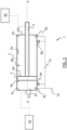
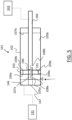
- FIG. 1 there is shown a schematic view of a single acting hydraulic actuator 1 according to a first embodiment of the invention.
- the actuator 1 is ⁇ single acting' in that pressurised hydraulic fluid is used to drive the actuator 1 in a single direction only (in this case to drive the piston 3 and piston rod 4 from a retracted position to an extended position), as described in further detail below.
- the actuator 1 comprises a hollow cylindrical housing 2 that extends from a first end 21a to a second end 21b along a central longitudinal axis A.
- a cylindrical cavity 60 is provided in the housing 2.
- a piston 3 is slidably mounted in the cavity 60 for relative movement with respect to the housing 2.
- a piston rod 4 is connected to the piston 3 such that the piston rod 4 is fixed relative to the piston 3. In this respect, the piston 3 and piston rod 4 move together, relative to the housing 2.
- the piston rod 4 is attached to a second side 6b of the piston 3 (described in more detail below) and extends out of the second end 21b of the housing 2, through a bore in the second side 21b.
- the piston 3 is slidably mounted in the cavity 60 for relative movement with respect to the housing 2, along the longitudinal axis A, such that the piston 3 and piston rod 4 are movable relative to the housing 2 between a retracted position (shown in Figure 3a ) and an extended position (shown in Figure 3d ).
- a seal (not shown) is provided between the piston 3 and the housing 2.
- the housing 2 has a first interior side 7a (at the first end 21a of the housing 2) that faces an opposed first surface 6a of the piston 3. Similarly, the housing 2 has a second interior side 7b (at the second end 21b of the housing 2), that faces an opposed second surface 6b of the piston 3.
- the piston 3 divides the cavity 60 into first and second pressure chambers 5a, 5b such that the volume of one of the pressure chambers is increased and the volume of the other is decreased as the piston 3 is moved relative to the housing 2.
- the housing 2 and piston 3 define a first pressure chamber 5a between the first side 6a of the piston 3 and the opposed first interior side 7a of the housing 2 and a second pressure chamber 5b between the second side 6b of the piston 3 and the opposed second interior side 7b of the housing 2.
- the first and second pressure chambers 5a, 5b each have a first port 8a, 8b and a second port 9a, 9b.
- the first and second ports 8a, 9a of the first pressure chamber 5a are positioned towards the first interior side 7a of the housing 2 and the first and second ports 8b, 9b of the second pressure chamber 5b are positioned towards the second interior side 7b of the housing 2.
- the second port 9a, 9b is positioned outboard of the first port 8a, 8b.
- the second port 9a, 9b is positioned between the first port 8a, 8b and the first or second opposed interior side 7a, 7b of the housing 2 respectively.
- the first and second ports 8a, 9a, 8b, 9b of the first and second pressure chambers 5a, 5b are connected to each other by an external connection in the form of a common hydraulic line 51 of an actuation system (as described in further detail below).
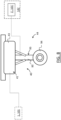
- Each port 8a, 8b, 9a, 9b is a respective aperture in the housing 2 that allows the passage of hydraulic fluid into and out of the respective pressure chambers 5a, 5b.
- each port 8a, 8b, 9a, 9b is a circular aperture.
- the second port 9a, 9b has a smaller cross-sectional area than the first port 8a, 8b (as shown in Figure 2 and discussed further below).
- the aircraft 61 is a passenger aircraft comprising a passenger cabin comprising a plurality of rows and columns of seat units for accommodating a multiplicity of passengers, in this case more than 50 passengers.
- the aircraft has a pair of the wings 62.
- the aircraft 61 is a powered aircraft and comprises engines 63, mounted under the wings 62, for propelling the aircraft 61.
- the aircraft 61 may be any type of aircraft, including any air vehicle, such as a manned aircraft or a UAV. However, the aircraft 61 is preferably a passenger aircraft.
- the aircraft 61 comprises a landing gear system 40.
- the landing gear system 40 comprises a first landing gear assembly 41 and a first actuation system 42 (shown in Figures 8 to 13 ) configured to actuate the first landing gear assembly 41.
- the first landing gear assembly 41 comprises a pair of landing gear bay doors 43 (only one of which is shown in Figure 8 ) that are movable between an open configuration (as shown in Figure 8 ) and a closed configuration (as shown in Figure 7 ).
- the first actuation system 42 comprises the actuator 1 of the first embodiment (or of the second embodiment 101, described below), which is configured to actuate the bay doors 43 from their open position to their closed position.
- the actuator housing 2 is attached to a fixed anchor point 31 of the aircraft 61 (shown schematically in Figure 1 by a dotted line that connects the housing 2 to a box labelled 31) and the piston rod 4 is mechanically connected to the bay doors 43 such that when the piston 3 (and piston rod 4) is in the extended position the bay doors 43 are in their closed configuration and when the piston 3 (and piston rod 4) is in its retracted position the bay doors 43 are in their open configuration.
- this mechanical connection is shown schematically by a dotted line connecting the actuator 1 to the bay doors 43. It will be appreciated that any suitable means of connection may be used to provide the desired kinematic movement of the bay doors 43.
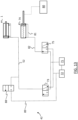
- first and second ports 8a, 9a, 8b, 9b of the first and second pressure chambers 5a, 5b are connected to each other by an external connection in the form of a common hydraulic line 51.
- the common hydraulic line 51 is connected to a pump 71 via a first selector valve 73.
- the selector valve is a three-way, two-position valve.
- any form of flow control may be used.
- each pressure chamber 5a, 5b are connected, by the common hydraulic line 51 to a single inlet line 52 that is selectively fluidly connectable to a pump 71 or hydraulic fluid reservoir 72 via the selector valve 73.
- a single inlet line 52 may allow the actuation system 42, and the landing gear system 40, to be relatively simple, compact and reliable.
- the first actuation system 42 also comprises second actuator 74, which is a single acting actuator that corresponds to the first actuator 1, except in that each pressure chamber only has a single port 70, 76 (which acts as an inlet and outlet for hydraulic fluid).
- each pressure chamber is connected, by a common hydraulic line 81 to a single inlet line 82 that is selectively connectable to the pump 71 or hydraulic fluid reservoir 72 via a second selector valve 75.
- the use of a single inlet line 82 may allow the actuation system 42, and the landing gear system 40, to be relatively simple, compact and reliable.
- the second actuator 74 is mechanically connected to an uplock 80 (shown schematically in Figure 9 ) such that when the piston 78 (and piston rod 79) are in the extended position the uplock 80 is in an unlocked configuration in which the landing bay doors 43 are unlocked from their closed position and are able to move to their open position and when the piston 78 (and piston rod 79) are in the retracted position the uplock 80 is in a locked configuration in which the landing bay doors 43 are locked in their closed position.
- an uplock 80 shown schematically in Figure 9
- the first landing gear assembly 41 is in a first configuration in which the landing gear bay doors 43 are in the open position and the uplock 80 is in its unlocked position.
- the first selector valve 73 is in a position that connects the inlet line 52 (and therefore the first and second ports of the first and second pressure chambers 5a, 5b of actuator 1) to the reservoir 72 (and not to the pump 71).
- the first actuator 1 is depressurised, the piston 3 (and piston rod 4) is in its retracted position and the landing gear bay doors 43 are in their open position (described in more detail below).
- the second selector valve 75 is in a position that connects the ports 70, 76 of the second actuator 74 to the pump 71 such that pressurised hydraulic fluid is supplied by the pump 71 to the first and second pressure chambers of the second actuator 74.
- the pump 71 pressurises the hydraulic fluid in the first and second pressure chambers 66a, 66b of the second actuator 74 to substantially the same pressure.
- the first side 78a of the piston 78 has an exposed surface area that is greater than the exposed surface area of the second side 78b of piston 78.
- the first selector valve 73 is moved to a position in which it connects the pump 71 to the first and second ports of the first and second pressure chambers 5a, 5b of the first actuator 1.
- the pump 71 pressurises the hydraulic fluid in the first and second pressure chambers 5a, 5b to substantially the same pressure P1.
- the first side 6a of the piston 3 has an exposed surface area (A1) that is greater than the exposed surface area (A2) of the piston 3 on its second side 6b.
- A1 exposed surface area
- A2 exposed surface area
- the first side 6a of the piston 3 is a circular disc, with an exposed surface area (A1) and the second side 6b is an annular surface (that as a corresponding disc shape but with the central circular cross-sectional area of the piston rod 4 removed from it).
- the force (F1) acting on the first side 6a of the piston 3 due to the pressure (P1) in the first pressure chamber 5a is greater than the force (F2) acting on the second side 6b of the piston 3 due to the pressure (P2) in the second pressure chamber 5b.
- the rear side of the piston 3 has a greater cross-sectional area than the front side, this may allow for a reduction in the overall size of the actuator 1, as the 'powered' direction of actuation is always performed on the side of the piston 3 that has the greater cross-sectional area.
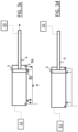
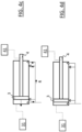
- the first and second ports 8b, 9b of the second pressure chamber 6b are positioned such that as the piston 3 is moved from its retracted position, towards the first port 8b of the second pressure chamber 6b, the first and second ports 8b, 9b (of the second pressure chamber 5b) are open, allowing hydraulic fluid to flow out of the second pressure chamber 5b through the first and second ports 8b, 9b (as shown in Figures 3a and 3b ).
- the hydraulic fluid is conveyed out of the second pressure chamber 6b due to the movement of the piston 3.
- the hydraulic fluid passing out of the first and second ports 8b, 9b of the second pressure chamber 5b is conveyed to the first pressure chamber 5a, through the first and second ports 8a, 9a of the first pressure chamber, via the common hydraulic line 51.
- the first and second ports of each of the chambers 5a, 5b are also inlets.
- This return flow path (R) of the hydraulic fluid may advantageously reduce the amount of hydraulic fluid required to be delivered by the pump 71, thereby reducing the overall size of the landing gear system.
- the return flow path (R) allows the actuation system to have a closed system of hydraulic fluid.
- the actuator 1 is unvented.
- the actuator 1 is sealed.
- the first and second pressure chambers 5a, 5b are not open to the atmosphere and the return flow path (R) is not open to the atmosphere.
- the only inlets and outlets to the pressure chambers 5a, 5b are provided by the respective first and second ports 8a, 8b, 9a, 9b.
- This closed system of hydraulic fluid prevents the ingress of moisture and freezing during use of the aircraft landing gear assembly 41.
- hydraulic fluid is only able to flow out of the second pressure chamber 5b through the second port 9b.
- the second port 9b is configured to provide a restricted flow of hydraulic fluid out of the second pressure chamber 5b, relative to the first port 8b.
- the second port 9b has a smaller cross-sectional area than the first port 8b (as described above).
- the restricted flow acts to slow the subsequent movement of the piston 3 to the extended position, thereby slowing the movement of the bay doors 43 to their closed position. Accordingly this provides a snubbing effect during the closing of the bay doors 43.
- the second actuator 74 is depressurised, by moving the selector valve 75 to the position shown in Figure 11 in which the inlet line 82 is disconnected from the pump 71 and connected to the fluid reservoir 72.
- a ⁇ load-relief' method is employed.
- the first selector valve 73 is positioned as shown in Figure 11 , so as to pressurise the first actuator 1. This acts to pull the doors 43 closed (load relief).
- the second selector valve 75 is then moved to the position shown in Figure 12 , so as to pressurised the second actuator 74, to move the uplock 80 to its unlocked position.
- the first selector valve 73 is then moved to the position shown in Figure 13 , in which the first actuator 1 is disconnected from the pump 71 and connected to the fluid reservoir 72, so as to depressurise the first actuator 1.
- the bay doors 43 are then moved, under their own weight, as well as aerodynamic loads, from their closed position to their open position.
- the invention recognises that the first actuator 1 is not required to actively drive the bay doors 43 from their closed position to the open position and so a single acting actuator 1 may be used to actuate the bay doors 43.
- the first and second ports 8a, 9a of the first pressure chamber 5a are positioned such that, during movement from the extended position to the retracted position, as the piston 3 is moved from its extended position, towards the first port 8a, the first and second ports 8a, 9a are open, allowing hydraulic fluid to flow out of the first pressure chamber 5a through the first and second ports 8a, 9a (as shown in Figures 4a and 4b ).
- the hydraulic fluid passing out of the first and second ports 8a, 9a of the first pressure chamber 5a is conveyed to the second pressure chamber 5b, through the first and second ports 8b, 9b of the second pressure chamber, via the common hydraulic line 51,, due to the movement of the piston 3.
- the piston 3 When the piston 3 reaches the first port 8a (as shown in Figure 4c ), it acts to block the first port 8a, thereby preventing the flow of hydraulic fluid from the first pressure chamber 5a, through the first port 8a. The piston 3 continues to block the first port 8a as the piston 3 continues to move to the retracted position (shown in Figure 4d ).
- the second port 9a is configured to provide a restricted flow of hydraulic fluid out of the first pressure chamber Sa, relative to the first port 8a.
- the second port 9a has a smaller cross-sectional area than the first port 8a (as described above and shown in Figure 2 ).
- the restricted flow acts to slow the subsequent movement of the piston 32 to the retracted position, thereby slowing the movement of the landing gear bay doors 43 to their open position. Accordingly this provides a snubbing effect during the opening of the landing gear bay doors 43.
- the actuation system 42 also comprises an emergency bypass line 89 (see Figure 9 ) that connects the inlet line 52, at a point downstream stream of the first selector valve 73 but upstream of the first actuator 1, to the fluid reservoir 72.
- a combined vent and door bypass valve 88 is located in the emergency bypass line 89 and is selectively movable between an open position, which allows hydraulic fluid to flow from the actuator 1 along the emergency line 89 to the reservoir 72, and a closed position which prevents said flow, by a pilot input (i.e. an input made by a pilot of the aircraft).
- the aircraft pilot may move the valve 88 to its open position. This provides for freefall extension of the bay doors 43, under gravity and aerodynamic loads on the bay doors 43, as it allows the hydraulic fluid to flow directly out of the first pressure chamber 5a to the fluid reservoir 72.
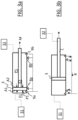
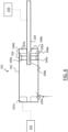
- FIG. 5 there is shown a schematic view of an actuator 101 according to a second aspect of the invention.
- the actuator of the second aspect has corresponding features to those of the first aspect, except for the differences described below. Corresponding features are provided with corresponding reference numerals, but incremented by 100.
- the actuator 101 of the second embodiment has corresponding features to those of the first embodiment expect in that it has a different arrangement of first and second ports, to provide the snubbing effect.
- first port 108a, 108b of each chamber 105a, 105b is provided in the piston rod 104, with the first ports 108a, 108b connected by an internal connecting flow path 190, that passes through the piston rod 104.
- the second ports 109a, 109b of the first and second chambers 105a, 105b are provided in the first and second sides of the piston 103 respectively and are connected by an internal connecting flow path 191.
- the first port 108a, 108b of the decreasing volume chamber is blocked by the end of the housing 102 (as shown in Figure 6 for the extended position- it will be appreciated that in the retracted position the end 146 of the piston rod 104 that extends rearwardly of the piston 103 is received in a bore 147 at the first end of the housing 102), thereby preventing flow through the first port 108a, 108b (and connecting flow path 190), such that hydraulic fluid may only flow out of the chamber (and into the increasing volume chamber) through the second port 109a, 109b (and connecting flow path 191).
- the second port 109a, 109b has a smaller cross-sectional area than the first ports 108a, 108b. Accordingly, the flow of hydraulic fluid out of the decreasing volume chamber is restricted as the piston 3 nears its extended or retracted positions, thereby providing the same snubbing effect as in the first embodiment of the invention.
- a second landing gear assembly 44 comprises landing gear 93 that is movable between a deployed configuration (shown in Figure 8 ) and a retracted configuration (shown in Figure 7 ).
- the landing gear 93 comprises a pair of wheels 94 rotatably mounted on an end of a landing gear strut assembly 95.
- the landing gear 93 When the landing gear 93 is in its deployed configuration, the aircraft 61 is in a configuration for movement along the ground (e.g. during landing, take off and taxiing), with the landing gear 93 supporting the weight of the aircraft 61.
- the landing gear 93 When the landing gear 93 is in its retracted configuration it is retracted within the aircraft 61 (e.g. within the fuselage and/or wings of the aircraft) to provide a configuration of the aircraft for flight (e.g. to reduce drag on the aircraft).
- a second actuation system 142 (shown schematically in Figure 8 ), which has corresponding features to the first actuator system (i.e. it comprises a second pair of said first and second actuators 1, 101, 74 arranged in a corresponding hydraulic fluid circuit), is used in a corresponding way to actuate the landing gear 93 between its deployed and retracted configurations (and to lock and unlock the landing gear 93 in its retracted configuration).
- the actuator 1 may be used with any type of landing gear, including nose landing gear and main (rear) landing gear.
- the landing gear may have one or more wheels, skis, etc.
- the actuator may be used to actuate different landing gear assemblies to those referred to above and is not limited to the use with landing gear or landing gear bay doors.
- an actuator for an aircraft landing gear assembly may only be required to generate an actuating force in a single direction.
- an actuating force may only be required to retract a landing gear assembly (for example landing gear or landing gear bay doors), with the deployment primarily achieved by the weight the landing gear assembly and/or aerodynamic force on the landing gear assembly.
- the arrangement of the first and second outlets of the first and second pressure chambers, to slow the movement of the piston relative to the housing in the second stage of the relative movement, may slow the relative movement of the piston and housing towards the end of travel of the actuator, to the retracted and/or extended positions, which may thereby reduce impact loads on the actuator and/or landing gear assembly.
- the first and second outlets provide a snubbing effect. This is particularly important, when used to actuate a landing gear assembly, due to the typically high loads involved (e.g. due to relatively high weight of the landing gear assembly and/or the relatively high aerodynamic forces on the landing gear assembly).
- first and second outlets may provide a particularly effective means of snubbing a single acting actuator.
- the provision of first and second outlets may allow for a relatively high flow rate of actuator fluid out of the decreasing volume pressure chamber during the first stage of relative movement whilst also allowing for a relatively large reduction in the outlet flow rate during the second stage.
- the first and second outlets may be positioned relative to each other so as to provided for a desired snubbing behaviour throughout the movement of the piston relative to the housing, based on the requirements of the actuation.
- the actuator 1, 101 uses return flow of the hydraulic fluid, from one pressure chamber to the other, this may advantageously reduce the amount of hydraulic fluid required by the actuator 1, 101. This may allow the actuator 1, 101 to be relatively simple and compact, which is particularly important in aircraft design. In addition, it may allow for an overall reduction in the size and power required of an actuator fluid system of an actuation system comprising the actuator.
- connection may allow the actuator to be sealed with respect to the external atmosphere, in a relatively compact way, without requiring a complicated actuator fluid circuit.
- the use of a sealed actuator may prevent the ingress of moisture, into the actuator, and freezing of this moisture during use of the aircraft landing gear assembly.
- the housing 2 is attached to a fixed anchor point 31 of the aircraft 61 and the piston rod 4 is attached to the bay doors or landing gear such that, as the piston 3 moves between its extended and retracted positions, the piston 3 moves and the housing 2 is stationary.
- the housing 2 may be moved and the piston 3 may be stationary, or both the piston 3 and housing 2 may be moved, so as to provide this relative movement.
- the piston 3 may be attached to the anchor point 31, with the actuator housing 2 connected to the bay doors or landing gear. In this case the piston 3 will be stationary (relative to the anchor point 31) with the housing 2 moving so as to effect the movement of the bay doors or landing gear.
- the piston 3 and housing 2 are movable relative to each other from the retracted position to the extended position under the action of pressure of actuator fluid in the first and second pressure chambers and are movable relative to each other from the extended position to the retracted position by movement of the landing gear assembly due to a force acting on the landing gear assembly (e.g. force due to gravity and/or aerodynamic forces).
- the piston and housing may be movable relative to each other from the extended position to the retracted position under the action of pressure of actuator fluid in the first and second pressure chambers and movable relative to each other from the retracted position to the extended position by movement of the landing gear assembly due to a force acting on the landing gear assembly (e.g. force due to gravity and/or aerodynamic forces).
- the piston and housing are moved relative to each other from the retracted position to the extended position actuator fluid by pressurising the actuator fluid in the first and second pressure chambers 5a, 5b to substantially the same pressure P1, with the first side 6a of the piston 3 having an exposed surface area (A1) that is greater than the exposed surface area (A2) of the piston 3 on its second side 6b so that a net resultant force moves the piston 3 (and piston rod 4) from its retracted position to its extended position.
- the pressure chambers may be provided with different pressures of actuator fluid so as to move the piston and housing relative to each other from the retracted position to the extended position (or from the extended position to the retracted position).
- the first and second sides 6a, 6b of the piston may have the same (or different) exposed cross-sectional areas.
- the second port 9a, 9b has a smaller cross-sectional area than the first port 8a, 8b, so as to restrict the outlet flow relative to the first port.
- any suitable arrangement may be used to provide this restricted flow.
- a flow path out of the pressure chamber 5a, 5b from the second port 9a, 9b may provide a resistance to the flow of the actuator fluid out of the second port 9a, 9b such that the flow through the second port 9a, 9b, out of the respective pressure chamber 5a, 5b, is restricted relative to the first port 8a, 8b. This may, for example, be due to the pressure of actuator fluid in the flow path.
- the flow through the second port may not be restricted relative to the flow through the first port.
- the first and second ports may have the same cross-sectional size and shape.
- the return flow path connects the first and second ports 8b, 9b of the second pressure chamber 5b to the first and second ports 8a, 9a of the first pressure chamber 5a.
- This may provide an especially high return flow rate of actuator fluid, thereby providing for a particularly high reduction in the amount of actuator fluid required.
- the return flow path may connect the first and/or second ports of the second pressure chamber to the first and/or second ports of the first pressure chamber, to provide the return flow.
- the hydraulic fluid is oil.
- any suitable actuation fluid may be used, including a hydraulic fluid and/or pneumatic fluid (e.g. air).
Landscapes
- Engineering & Computer Science (AREA)
- Mechanical Engineering (AREA)
- Physics & Mathematics (AREA)
- Fluid Mechanics (AREA)
- General Engineering & Computer Science (AREA)
- Aviation & Aerospace Engineering (AREA)
- Business, Economics & Management (AREA)
- Emergency Management (AREA)
- Actuator (AREA)
Abstract
Description
- The present invention relates to a single acting actuator for an aircraft landing gear assembly. The present invention also relates to an actuation system for an aircraft landing gear assembly, an aircraft landing gear system and a method of actuation of an aircraft landing gear assembly.
- Actuators for aircraft landing gear assemblies, for example to actuate landing gear bay doors and/or landing gear are typically dual acting actuators. In this respect actuator fluid (e.g. hydraulic fluid) in a first pressure chamber is pressurised so as to move a piston of the actuator, relative to a body of the actuator, from a retracted position to an extended position and actuator fluid in a second pressure chamber is pressurised so as to move the piston, relative to the body of the actuator, in the opposite direction from the extended position to the retracted position. However dual acting actuators are relatively complex and so are relatively expensive, heavy and prone to malfunction.
- Furthermore, due to the typically high loads involved with extension and/or retraction of an aircraft landing gear assembly (e.g. due to high weight of the moving parts and/or aerodynamic loads), there is a requirement for an actuator for an aircraft landing gear assembly to have a means of slowing the actuator towards the end of its travel, to reduce impact loads on the actuator and/or landing gear assembly.
-
GB2470499A - The present invention seeks to address or mitigate at least some of the above mentioned problems. Alternatively, or additionally, the present invention seeks to provide an improved single acting actuator for an aircraft landing gear assembly. Alternatively, or additionally, the present invention seeks to provide an improved an actuation system for an aircraft landing gear assembly. Alternatively, or additionally, the present invention seeks to provide an improved aircraft landing gear system. Alternatively, or additionally, the present invention seeks to provide an improved method of actuation of an aircraft landing gear assembly.
- According to a first aspect of the invention there is provided a single acting actuator for an aircraft landing gear assembly, the actuator comprising:
- a housing;
- a cavity provided in the housing;
- a piston and a piston rod connected to the piston;
- the piston being mounted in the cavity for relative movement with respect to the housing such that the piston and piston rod are movable relative to the housing between a retracted position and an extended position;
- the piston dividing the cavity into first and second pressure chambers such that the volume of one of the pressure chambers is increased and the volume of the other is decreased as the piston is moved relative to the housing;
- the piston being movable relative to the housing from one of the retracted and extended positions to the other by a resultant force on the piston due to the pressure of actuator fluid in the first and second pressure chambers;
- wherein at least one of the pressure chambers is associated with first and second outlets, with the actuator being arranged such that, in respect of the relative movement in which the pressure chamber is the decreasing volume pressure chamber, in a first stage of the relative movement the first and second outlets are open thereby allowing actuator fluid to flow out of the pressure chamber through the first and second outlets and in a second stage of the relative movement the second outlet is open but the first outlet is closed, thereby acting to slow the relative movement of the piston with respect to the housing.
- The present invention recognises that an actuator for an aircraft landing gear assembly may only be required to generate an actuating force in a single direction. For example an actuating force may only be required to retract a landing gear assembly (for example landing gear or landing gear bay doors), with the deployment primarily achieved by the weight the landing gear assembly and/or aerodynamic force on the landing gear assembly.
- The arrangement of the first and second outlets, to slow the movement of the piston relative to the housing in the second stage of the relative movement may slow the relative movement of the piston and housing towards the end of travel of the actuator, to the retracted and/or extended positions, which may thereby reduce impact loads on the actuator and/or landing gear assembly. In this respect, the first and second outlets provide a snubbing effect. This is particularly important, when used to actuate a landing gear assembly, due to the typically high loads involved (e.g. due to relatively high weight of the landing gear assembly and/or the relatively high aerodynamic forces on the landing gear assembly).
- The provision of the first and second outlets may provide a particularly effective means of snubbing a single acting actuator. In this respect, the provision of first and second outlets may allow for a relatively high flow rate of actuator fluid out of the decreasing volume pressure chamber during the first stage of relative movement whilst also allowing for a relatively large reduction in the outlet flow rate during the second stage. In this respect, the second outlet may be configured such that the flow through the second outlet, out of the decreasing volume pressure chamber, is restricted relative to the first outlet (see below). Also the first and second outlets may be positioned relative to each other so as to provided for a desired snubbing behaviour throughout the movement of the piston relative to the housing, based on the requirements of the actuation.
- In embodiments of the invention the piston is movable relative to the housing from the other of the retracted and extended positions to the one of the retracted and extended positions under the action of a force on a landing gear assembly, when the actuator is arranged with a landing gear assembly so as to actuate the landing gear assembly.
- It will be appreciated that the first and second outlets are distinct outlets, i.e. they are not the same outlet. The first and second outlets may be spaced apart from each other.
- It will be appreciated that when the piston and piston rod are in the extended position the piston rod extends further out of the housing than when the piston and piston rod are in the retracted position.
- Optionally when the piston is moved relative to the housing from the extended position to the retracted position, the first pressure chamber is the decreasing volume pressure chamber and the second pressure chamber is the increasing volume pressure chamber and when the piston is moved relative to the housing from the retracted position to the extended position, the second pressure chamber is the decreasing volume pressure chamber and the first pressure chamber is the increasing volume pressure chamber.
- In embodiments of the invention the first pressure chamber has at least one inlet for actuator fluid. In embodiments of the invention the second pressure chamber has at least one inlet for actuator fluid. The at least one inlet may be formed by the first and/or second outlets associated with the pressure chamber.
- The first pressure chamber may be provided between a first side of the piston and an opposed side of the housing and the second pressure chamber may be provided between a second side of the piston and an opposed side of the housing. The first side of the piston may be on an opposite side of the piston to the piston rod. In this respect the second side of the piston may be on the same side of the piston as the piston rod. The second side of the piston may be on the side of the piston facing the direction of extension of the piston rod from the housing (when in the extended position).
- It will be appreciated that the second stage of relative movement occurs after the first stage. In embodiments of the invention the second stage of relative movement occurs towards the end of the movement of the piston relative to the housing to the retracted or extended position. In this respect, where the first pressure chamber is associated with the first and second outlets and the first pressure chamber is the decreasing volume pressure chamber, the second stage may occur towards the end of the relative movement to the retracted position. Where the second pressure chamber is associated with the first and second outlets and the second pressure chamber is the decreasing volume pressure chamber, the second stage may occur towards the end of the relative movement to the extended position.
- Optionally the actuator is configured such that the flow through the second outlet, out of the pressure chamber, is restricted relative to the flow through the first outlet, out of the pressure chamber. This may provide a particularly effective snubbing action, to slow the relative movement of the piston and housing. In this respect, the second outlet may be configured to provide a restricted flow of actuator fluid out of the respective pressure chamber, relative to the first outlet. For example, optionally the second outlet has a smaller cross-sectional area than the first outlet. Alternatively, or additionally, the second outlet may be shaped so as to provide said restricted flow. Alternatively, or additionally, a flow path out of the pressure chamber from the second outlet may provide a resistance to the flow of the actuator fluid out of the second outlet such that the flow through the second outlet, out of the respective pressure chamber, is restricted relative to the first outlet. This may, for example, be due to the pressure of actuator fluid in the connection.
- Optionally the first and second pressure chambers are connected such that actuator fluid flows from the decreasing volume pressure chamber to the increasing volume pressure chamber. In embodiments of the invention this fluid flow is solely due to the movement of the piston relative to the housing.
- The connection may reduce the amount of actuator fluid required by the actuator. This may allow the actuator to be relatively light weight and compact, which is particularly important in aircraft design. In addition, it may allow for an overall reduction in the size and power required of an actuator fluid system of an actuation system comprising the actuator.
- Alternatively, or additionally, the connection may allow the actuator to be sealed with respect to the external atmosphere, in a relatively compact way, without requiring a complicated actuator fluid circuit.
- Optionally the connection is configured such that actuator fluid flows from the decreasing volume pressure chamber to the increasing volume pressure chamber due to the movement of the piston relative to the housing from the other of the retracted and extended positions to the one of the retracted and extended positions under the action of a force on a landing gear assembly, when the actuator is arranged with a landing gear assembly so as to actuate the landing gear assembly.
- Optionally the connection is configured such that actuator fluid flows from the decreasing volume pressure chamber to the increasing volume pressure chamber due to the movement of the piston relative to the housing from the one of the retracted and extended positions to the other by a resultant force on the piston due to the pressure of actuator fluid in the first and second pressure chambers.
- Optionally the actuator is sealed with respect to the atmosphere. In this respect the actuator may be unvented. The first and second pressure chambers and the connection may be sealed with respect to the atmosphere. This may prevent the ingress of moisture, into the actuator, and freezing of this moisture during use of the aircraft landing gear assembly.
- The connection may connect the first and/or second outlets of the second pressure chamber to the first and/or second outlets of the first pressure chamber. In this respect, the flow path may connect the first and second outlets of the second pressure chamber to the first and second outlets of the first pressure chamber. This may provide for a transfer of flow, from one pressure chamber to the other, that has a particularly high flow rate, thereby providing for a particularly high reduction in the amount of actuator fluid required.
- Optionally both the first and second pressure chambers are associated with respective said first and second outlets. This may provide for the snubbing action in respect of both directions of movement of the piston relative to the housing, i.e. from the retracted position to the extended position and vice-versa.
- Optionally the first and/or second outlets associated with the, or each, pressure chamber is also an inlet for actuator fluid. This may allow the actuator to be relatively compact whilst providing a relative high flow rate of actuator fluid into the actuator.
- Optionally, in respect of the or each pressure chamber, the first and second outlets are provided in the housing, with the second outlet positioned outboard of the first outlet such that in the second stage of relative movement the piston closes the first outlet but not the second outlet. This may allow the actuator to be compact and reliable. Furthermore, because the first and second outlets are provided in the housing, this may allow for a particularly reliable way of providing the snubbing effect, that is easily accessible for inspection and maintenance.
- Optionally the connection comprises an external connection that connects the first and/or second outlets associated with the second pressure chamber to the first and/or second outlets associated with the first pressure chamber. It will be appreciated that an `external' flow path is a flow path that is external to the housing. This may allow for a relatively straightforward and reliable way of connecting the actuator to an actuator fluid system.
- Optionally, in respect of the or each pressure chamber, one of the first or second outlets is provided in the piston rod and the other is provided in the piston, such that during the second stage of relative movement the first outlet is closed by a part of the actuator. This may allow the actuator to be relatively compact, as the outlets, that provide the snubbing action, and transfer path are provided within the housing.
- Optionally both the first and second pressure chambers are associated with respective said first and second outlets, the outlets in the piston rod are connected by a first flow path and the outlets in the piston are connected by a second flow path such that the connection comprises the first and second flow paths. This may provide for a compact arrangement that still provides a high flow rate of actuator fluid between the pressure chambers.
- Optionally the connection comprises an internal flow path. For example, the connection may pass across the piston. The connection may pass through the piston and/or piston rod. Such an arrangement may allow the actuator to be relatively compact.
- Optionally the rear side of the piston, in relation to the direction of movement of the piston relative to the housing due to the pressure of actuator fluid in the first and second pressure chambers, has a greater exposed cross-sectional area than the front side of the piston. This may allow for a reduction in the overall size of the actuator, as the 'powered' direction of actuation is always performed on the side of the piston that has the greater cross-sectional area. In this case, the actuator fluid in the first and second pressure chambers may be pressurised, by the pump, to substantially the same pressure to move the piston being relative to the housing from one of the retracted and extended positions to the other. Alternatively, the pressure in the first and second chambers may be different.
- Optionally the actuator fluid is hydraulic fluid. Alternatively, or additionally, the actuator fluid may be a pneumatic fluid (e.g. air).
- According to a second aspect of the invention there is provided a single acting actuator for an aircraft landing gear assembly, the actuator comprising:
- a housing;
- a cavity provided in the housing;
- a piston and a piston rod connected to the piston;
- the piston being mounted in the cavity for relative movement with respect to the housing such that the piston and piston rod are movable relative to the housing between a retracted position and an extended position;
- the piston dividing the cavity into first and second pressure chambers such that the volume of one of the pressure chambers is increased and the volume of the other is decreased as the piston is moved relative to the housing;
- the piston being movable relative to the housing from one of the retracted and extended positions to the other by a resultant force on the piston due to the pressure of actuator fluid in the first and second pressure chambers;
- wherein the first and second pressure chambers are connected such that actuator fluid flows from the decreasing volume pressure chamber to the increasing volume pressure chamber;
- and wherein the actuator is arranged such that in respect of the relative movement in which the first and/or second pressure chambers is the decreasing volume pressure chamber, in a second stage of the relative movement the flow of actuator fluid out of the pressure chamber is restricted, relative to a first stage of the relative movement, thereby acting to slow the relative movement.
- The second aspect of the invention recognises that an actuator for an aircraft landing gear assembly may only be required to generate an actuating force in a single direction (as with the first aspect of the invention). Furthermore, the slowing of the piston relative to the housing in the second stage of the relative movement may reduce impact loads on the actuator and/or landing gear assembly. The connection of the first and second pressure chambers may reduce the amount of actuator fluid required by the actuator. This may allow the actuator to be relatively light weight and compact, which is particularly important in aircraft design. In addition, it may allow for an overall reduction in the size and power required of an actuator fluid system of an actuation system comprising the actuator.
- According to a third aspect of the invention there is provided an actuation system for an aircraft landing gear assembly, the actuation system comprising:
- an actuator according to the first or second aspects of the invention;
- an actuator fluid reservoir;
- and a pump;
- arranged such that the pump is operable to pump actuator fluid from the reservoir to the actuator so as to pressurise actuator fluid in at least one of the first and second pressure chambers so as to move the piston relative to the housing from the one of the retracted and extended positions to the other.
- Optionally the connection does not pass through the pump.
- Optionally the actuation system has a closed system of actuator fluid. In this respect, the actuator fluid system is sealed with respect to the atmosphere. The actuator fluid system is unvented.
- Optionally the actuator is connected to a single inlet line, for supplying pressurised actuator fluid to at least one of the first and second pressure chambers.
- Optionally the actuation system comprises an inlet line that connects the pump to the actuator, for supplying pressurised actuator fluid to at least one of the first and second pressure chambers;
- a return line that connects the actuator to the actuator fluid reservoir, for passing actuator fluid from the actuator to the fluid reservoir, and
- a flow control that is selectively controllable between an open configuration in which it allows for actuator fluid to pass from the actuator to the actuator
- fluid reservoir and a closed configuration in which it prevents said return flow.
- Optionally the actuator is connected to the actuator fluid system by a single inlet line. This may allow for a reduction in weight due to fewer lines (e.g. pipes) and less actuator fluid required. It may also allow for fewer parts and so a more reliable system than in prior-art arrangements.
- Optionally the actuator is a first single acting actuator and the actuation system comprises a second single acting actuator;
the second actuator comprising: - a housing;
- a cavity provided in the housing;
- a piston and a piston rod connected to the piston;
- the piston being mounted in the cavity for relative movement with respect to the housing such that the piston and piston rod are movable relative to the housing between a retracted position and an extended position;
- the piston dividing the cavity into first and second pressure chambers such that the volume of one of the pressure chambers is increased and the volume of the other is decreased as the piston is moved relative to the housing;
- the piston being movable relative to the housing from one of the retracted and extended positions to the other by a resultant force on the piston due to the pressure of actuator fluid in the first and second pressure chambers;
- wherein the second actuator, pump and actuator fluid reservoir are connected such that the pump is operable to pump actuator fluid from the reservoir to the second actuator so as to pressurise actuator fluid in at least one of the first and second pressure chambers so as to move the piston relative to the housing from the one of the retracted and extended positions to the other.
- Optionally each of the first and second actuators is connected to a respective single inlet line, for supplying pressurised actuator fluid to at least one of the first and second pressure chambers of the actuator.
- Optionally the actuation system comprises a flow control arrangement configured such that the actuation system is controllable between a first configuration in which the piston of one of the actuators is in its extended position and the piston of the other of the actuators is in its retracted position and a second configuration in which the piston of the one of the actuators is in its retracted position and the piston of the other of the actuators is in its extended position.
- According to a fourth aspect of the invention there is provided an aircraft landing gear system comprising:
- an aircraft landing gear assembly; and
- an actuation system according to the third aspect of the invention or an actuator according to the first or second aspects of the invention;
- wherein the actuator is arranged such that the movement of the piston relative to the housing from the one of the retracted and extended positions to the other, by a resultant force on the piston due to the pressure of actuator fluid in the first and second pressure chambers, actuates the landing gear assembly from a first configuration to a second configuration;
- the landing gear assembly is movable from the second configuration to the first configuration under the action of a force on the landing gear assembly;
- and the actuator is arranged such that the movement of the landing gear assembly from the second configuration to the first configuration, under the action of said force, acts to move the piston relative to the housing from the other of the retracted and extended positions to said one of the retracted and extended positions.
- Optionally the force on the landing gear assembly comprises the weight of at least one component of the landing gear assembly and/or aerodynamic force on the landing gear assembly.
- Optionally the landing gear assembly comprises landing gear and/or a landing gear door.
- Optionally the landing gear system comprises a lock that is movable between a locked configuration and an unlocked configuration so as to lock and unlock the landing gear assembly in the second configuration; and the second actuator is arranged to actuate the lock between its locked configuration and its unlocked configuration.
- According to a fifth aspect of the invention there is provided an aircraft comprising an aircraft landing gear system according to the fourth aspect of the invention.
- According to a sixth aspect of the invention there is provided a method of actuation of an aircraft landing gear assembly using a single acting actuator, the actuator comprising:
- a housing;
- a cavity provided in the housing;
- a piston and a piston rod connected to the piston;
- the piston being mounted in the cavity for relative movement with respect to the housing such that the piston and piston rod are movable relative to the housing between a retracted position and an extended position;
- the piston dividing the cavity into first and second pressure chambers such that the volume of one of the pressure chambers is increased and the volume of the other is decreased as the piston is moved relative to the housing;
- the piston being movable relative to the housing from one of the retracted and extended positions to the other by a resultant force on the piston due to the pressure of actuator fluid in the first and second pressure chambers;
- wherein at least one of the pressure chambers is associated with first and second outlets, with the actuator being arranged such that, in respect of the relative movement in which the pressure chamber is the decreasing volume pressure chamber, in a first stage of the relative movement the first and second outlets are open thereby allowing actuator fluid to flow out of the pressure chamber through the first and second outlets and in a second stage of the relative movement the second outlet is open but the first outlet is closed, thereby acting to slow the relative movement of the piston with respect to the housing;
- wherein the method comprises:
- a) moving the piston relative to the housing from the one of the retracted and extended positions to the other, under the action of the pressure of actuator fluid in the first and second pressure chambers, so as to move the landing gear assembly from a first configuration to a second configuration; and
- b) moving the landing gear assembly from the second configuration to the first configuration under the action of a force on the landing gear assembly, thereby acting to move the piston relative to the housing from the other of the retracted and extended positions to said one of the retracted and extended positions.
- According to a seventh aspect of the invention there is provided a method of actuation of an aircraft landing gear assembly using a single acting actuator, the actuator comprising:
- a housing;
- a cavity provided in the housing;
- a piston and a piston rod connected to the piston;
- the piston being mounted in the cavity for relative movement with respect to the housing such that the piston and piston rod are movable relative to the housing between a retracted position and an extended position;
- the piston dividing the cavity into first and second pressure chambers such that the volume of one of the pressure chambers is increased and the volume of the other is decreased as the piston is moved relative to the housing;
- the piston being movable relative to the housing from one of the retracted and extended positions to the other by a resultant force on the piston due to the pressure of actuator fluid in the first and second pressure chambers;
- wherein the first and second pressure chambers are connected such that actuator fluid flows from the decreasing volume pressure chamber to the increasing volume pressure chamber;
- and wherein the actuator is arranged such that in respect of the relative movement in which the first and/or second pressure chambers is the decreasing volume pressure chamber, in a second stage of the relative movement the flow of actuator fluid out of the pressure chamber is restricted, relative to a first stage of the relative movement, thereby acting to slow the relative movement;
- wherein the method comprises:
- a) moving the piston relative to the housing from the one of the retracted and extended positions to the other, under the action of the pressure of actuator fluid in the first and second pressure chambers, so as to move the landing gear assembly from a first configuration to a second configuration; and
- b) moving the landing gear assembly from the second configuration to the first configuration under the action of a force on the landing gear assembly, thereby acting to move the piston relative to the housing from the other of the retracted and extended positions to said one of the retracted and extended positions.
- Optionally the force on the landing gear assembly comprises the weight of one or more parts of the landing gear assembly and/or an aerodynamic force acting on one or more parts of the landing gear assembly.
- The following Clauses set out further subject matter that forms part of the disclosure:
-
Clause 1. A single acting actuator for an aircraft landing gear assembly, the actuator comprising:- a housing;
- a cavity provided in the housing;
- a piston and a piston rod connected to the piston;
- the piston being mounted in the cavity for relative movement with respect to the housing such that the piston and piston rod are movable relative to the housing between a retracted position and an extended position;
- the piston dividing the cavity into first and second pressure chambers such that the volume of one of the pressure chambers is increased and the volume of the other is decreased as the piston is moved relative to the housing;
- the piston being movable relative to the housing from one of the retracted and extended positions to the other by a resultant force on the piston due to the pressure of actuator fluid in the first and second pressure chambers;
- wherein at least one of the pressure chambers is associated with first and second outlets, with the actuator being arranged such that, in respect of the relative movement in which the pressure chamber is the decreasing volume pressure chamber, in a first stage of the relative movement the first and second outlets are open thereby allowing actuator fluid to flow out of the pressure chamber through the first and second outlets and in a second stage of the relative movement the second outlet is open but the first outlet is closed, thereby acting to slow the relative movement of the piston with respect to the housing.
-
Clause 2. An actuator according toClause 1 wherein the actuator is configured such that the flow through the second outlet, out of the pressure chamber, is restricted relative to the flow through the first outlet, out of the pressure chamber. -
Clause 3. An actuator according to any preceding Clause wherein the first and second pressure chambers are connected such that actuator fluid flows from the decreasing volume pressure chamber to the increasing volume pressure chamber. -
Clause 4. An actuator according to any preceding Clause wherein both the first and second pressure chambers are associated with respective said first and second outlets. - Clause 5. An actuator according to any preceding Clause wherein the first and/or second outlets associated with the, or each, pressure chamber is also an inlet for actuator fluid.
- Clause 6. An actuator according to any preceding Clause wherein, in respect of the or each pressure chamber, the first and second outlets are provided in the housing, with the second outlet positioned outboard of the first outlet such that in the second stage of relative movement the piston closes the first outlet but not the second outlet.
- Clause 7. An actuator according to any of
Clauses 1 to 6 wherein, in respect of the or each pressure chamber, one of the first or second outlets is provided in the piston rod and the other is provided in the piston such that during the second stage of relative movement the first outlet is closed by a part of the actuator. - Clause 8. An actuator according to Clause 7, when dependent on
Clause 3, wherein both the first and second pressure chambers are associated with respective said first and second outlets, the outlets in the piston rod are connected by a first flow path and the outlets in the piston are connected by a second flow path such that the connection comprises the first and second flow paths. - Clause 9. A single acting actuator for an aircraft landing gear assembly, the actuator comprising:
- a housing;
- a cavity provided in the housing;
- a piston and a piston rod connected to the piston;
the piston being mounted in the cavity for relative movement with respect to the housing such that the piston and piston rod are movable relative to the housing between a retracted position and an extended position;
- the piston dividing the cavity into first and second pressure chambers such that the volume of one of the pressure chambers is increased and the volume of the other is decreased as the piston is moved relative to the housing;
- the piston being movable relative to the housing from one of the retracted and extended positions to the other by a resultant force on the piston due to the pressure of actuator fluid in the first and second pressure chambers;
- wherein the first and second pressure chambers are connected such that actuator fluid flows from the decreasing volume pressure chamber to the increasing volume pressure chamber; and wherein the actuator is arranged such that in respect of the relative movement in which the first and/or second pressure chambers is the decreasing volume pressure chamber, in a second stage of the relative movement the flow of actuator fluid out of the pressure chamber is restricted, relative to a first stage of the relative movement, thereby acting to slow the relative movement.
- Clause 10. An actuation system for an aircraft landing gear assembly, the actuation system comprising:
- an actuator according to any preceding Clause;
- an actuator fluid reservoir;
- and a pump;
- arranged such that the pump is operable to pump actuator fluid from the reservoir to the actuator so as to pressurise actuator fluid in at least one of the first and second pressure chambers so as to move the piston relative to the housing from the one of the retracted and extended positions to the other.
- Clause 11. An actuation system according to Clause 10 wherein:
- the actuation system comprises an emergency return line that connects the actuator to the actuator fluid reservoir, for passing actuator fluid from the actuator to the fluid reservoir, and
- a emergency return line flow control that is selectively controllable between an open configuration in which it allows actuator fluid to pass from the actuator to the actuator fluid reservoir and a closed configuration in which it prevents said return flow.
- Clause 12. An actuation system according to Clause 11 wherein:
- the actuator is a first actuator and the actuation system comprises a second actuator;
- the second actuator comprising:
- a housing;
- a cavity provided in the housing;
- a piston and a piston rod connected to the piston;
- the piston being mounted in the cavity for relative movement with respect to the housing such that the piston and piston rod are movable relative to the housing between a retracted position and an extended position;
- the piston dividing the cavity into first and second pressure chambers such that the volume of one of the pressure chambers is increased and the volume of the other is decreased as the piston is moved relative to the housing;
- the piston being movable relative to the housing from one of the retracted and extended positions to the other by a resultant force on the piston due to the pressure of actuator fluid in the first and second pressure chambers;
- wherein the second actuator, pump and actuator fluid reservoir are connected such that the pump is operable to pump actuator fluid from the reservoir to the second actuator so as to pressurise actuator fluid in at least one of the first and second pressure chambers so as to move the piston relative to the housing from the one of the retracted and extended positions to the other.
- Clause 13. An aircraft landing gear system comprising:
- an aircraft landing gear assembly; and
- an actuation system according to any of Clauses 10 to 12 or an actuator according to any of
Clauses 1 to 9; - wherein the actuator is arranged such that the movement of the piston relative to the housing from the one of the retracted and extended positions to the other, by a resultant force on the piston due to the pressure of actuator fluid in the first and second pressure chambers, actuates the landing gear assembly from a first configuration to a second configuration;
- the landing gear assembly is movable from the second configuration to the first configuration under the action of a force on the landing gear assembly;
- and the actuator is arranged such that the movement of the landing gear assembly from the second configuration to the first configuration, under the action of said force, acts to move the piston relative to the housing from the other of the retracted and extended positions to said one of the retracted and extended positions.
- Clause 14. An aircraft comprising an aircraft landing gear system according to Clause 13.
- Clause 15. A method of actuation of an aircraft landing gear assembly using a single acting actuator, the actuator comprising:
- a housing;
- a cavity provided in the housing;
- a piston and a piston rod connected to the piston;
- the piston being mounted in the cavity for relative movement with respect to the housing such that the piston and piston rod are movable relative to the housing between a retracted position and an extended position;
- the piston dividing the cavity into first and second pressure chambers such that the volume of one of the pressure chambers is increased and the volume of the other is decreased as the piston is moved relative to the housing;
- the piston being movable relative to the housing from one of the retracted and extended positions to the other by a resultant force on the piston due to the pressure of actuator fluid in the first and second pressure chambers;
- wherein at least one of the pressure chambers is associated with first and second outlets,
- with the actuator being arranged such that, in respect of the relative movement in which the pressure chamber is the decreasing volume pressure chamber, in a first stage of the relative movement the first and second outlets are open thereby allowing actuator fluid to flow out of the pressure chamber through the first and second outlets and in a second stage of the relative movement the second outlet is open but the first outlet is closed, thereby acting to slow the relative movement of the piston with respect to the housing;
- wherein the method comprises:
- a) moving the piston relative to the housing from the one of the retracted and extended positions to the other, under the action of a resultant force on the piston due to the pressure of actuator fluid in the first and second pressure chambers, so as to move the landing gear assembly from a first configuration to a second configuration; and
- b) moving the landing gear assembly from the second configuration to the first configuration under the action of a force on the landing gear assembly, thereby acting to move the piston relative to the housing from the other of the retracted and extended positions to said one of the retracted and extended positions.
- It will of course be appreciated that features described in relation to one aspect of the present invention may be incorporated into other aspects of the present invention. For example, the method of any aspect of the invention may incorporate any of the features described with reference to the apparatus of any aspect of the invention and vice versa.
- Other preferred and advantageous features of the invention will be apparent from the following description.
- Embodiments of the present invention will now be described by way of example only with reference to the accompanying drawings of which:
- Figure 1
- shows a schematic view of a single acting actuator according to a first embodiment of the invention, where the piston is in an intermediate position between a retracted position and an extended position and where a part of an actuation system is shown;
- Figure 2
- is a view corresponding to
Figure 1 , but showing the first and second ports, of each pressure chamber, in more detail, and where the cross-sectional shape of the outlets is shown beneath them; - Figures 3a to 3d
- are views corresponding to that of
Figure 1 , but where the piston is sequentially shown moving from the retracted position to the extended position; - Figures 4a to 4d
- are views corresponding to that of
Figure 1 , but where the piston is sequentially shown moving from the extended position to the retracted position; - Figure 5
- is a schematic view of a single acting actuator according to a second embodiment of the invention, where the piston is in an intermediate position between a retracted position and an extended position and where a part of an actuation system is shown;
- Figure 6
- is a view corresponding to
Figure 5 but where the piston (and piston rod) is in an its extended position; - Figure 7
- shows an aircraft comprising a landing gear system according to an embodiment of the invention, where landing gear of the landing gear system is in a retracted configuration;
- Figure 8
- shows a schematic side view of the landing gear of the landing gear system of the aircraft in
Figure 7 , where the landing gear is in a deployed configuration; and - Figures 9 to 13
- shows a fluid circuit diagram of an actuation system of the landing gear system in
Figures 7 and8 , where the landing gear system is in various configurations. - Referring to
Figure 1 there is shown a schematic view of a single actinghydraulic actuator 1 according to a first embodiment of the invention. Theactuator 1 is `single acting' in that pressurised hydraulic fluid is used to drive theactuator 1 in a single direction only (in this case to drive thepiston 3 andpiston rod 4 from a retracted position to an extended position), as described in further detail below. - The
actuator 1 comprises a hollowcylindrical housing 2 that extends from afirst end 21a to asecond end 21b along a central longitudinal axis A. Acylindrical cavity 60 is provided in thehousing 2. - A
piston 3 is slidably mounted in thecavity 60 for relative movement with respect to thehousing 2. Apiston rod 4 is connected to thepiston 3 such that thepiston rod 4 is fixed relative to thepiston 3. In this respect, thepiston 3 andpiston rod 4 move together, relative to thehousing 2. Thepiston rod 4 is attached to asecond side 6b of the piston 3 (described in more detail below) and extends out of thesecond end 21b of thehousing 2, through a bore in thesecond side 21b. - The
piston 3 is slidably mounted in thecavity 60 for relative movement with respect to thehousing 2, along the longitudinal axis A, such that thepiston 3 andpiston rod 4 are movable relative to thehousing 2 between a retracted position (shown inFigure 3a ) and an extended position (shown inFigure 3d ). A seal (not shown) is provided between thepiston 3 and thehousing 2. - It will be appreciated that in the extended position the
piston rod 4 extends further out of thesecond end 21b of thehousing 2 than it does in the retracted position. - The
housing 2 has a firstinterior side 7a (at thefirst end 21a of the housing 2) that faces an opposedfirst surface 6a of thepiston 3. Similarly, thehousing 2 has a secondinterior side 7b (at thesecond end 21b of the housing 2), that faces an opposedsecond surface 6b of thepiston 3. - When the
piston 3 is in its retracted position (shown inFigure 3a ) it is proximal to the firstinterior side 7a of thehousing 2 and when thepiston 3 is in its extended position it is proximal to the secondinterior side 7b of thehousing 2. - The
piston 3 divides thecavity 60 into first andsecond pressure chambers piston 3 is moved relative to thehousing 2. In this respect, thehousing 2 andpiston 3 define afirst pressure chamber 5a between thefirst side 6a of thepiston 3 and the opposed firstinterior side 7a of thehousing 2 and asecond pressure chamber 5b between thesecond side 6b of thepiston 3 and the opposed secondinterior side 7b of thehousing 2. - The first and
second pressure chambers first port second port second ports first pressure chamber 5a are positioned towards the firstinterior side 7a of thehousing 2 and the first andsecond ports second pressure chamber 5b are positioned towards the secondinterior side 7b of thehousing 2. - In respect of each
pressure chamber second port first port second port first port interior side housing 2 respectively. The first andsecond ports second pressure chambers hydraulic line 51 of an actuation system (as described in further detail below). - Each
port housing 2 that allows the passage of hydraulic fluid into and out of therespective pressure chambers port pressure chamber second port first port Figure 2 and discussed further below). - Referring to
Figure 7 , there is shown a front view of anaircraft 61 according to an embodiment of the invention. Theaircraft 61 is a passenger aircraft comprising a passenger cabin comprising a plurality of rows and columns of seat units for accommodating a multiplicity of passengers, in this case more than 50 passengers. The aircraft has a pair of thewings 62. Theaircraft 61 is a powered aircraft and comprisesengines 63, mounted under thewings 62, for propelling theaircraft 61. Theaircraft 61 may be any type of aircraft, including any air vehicle, such as a manned aircraft or a UAV. However, theaircraft 61 is preferably a passenger aircraft. - Referring to
Figure 8 , theaircraft 61 comprises alanding gear system 40. Thelanding gear system 40 comprises a firstlanding gear assembly 41 and a first actuation system 42 (shown inFigures 8 to 13 ) configured to actuate the firstlanding gear assembly 41. - In this respect, the first
landing gear assembly 41 comprises a pair of landing gear bay doors 43 (only one of which is shown inFigure 8 ) that are movable between an open configuration (as shown inFigure 8 ) and a closed configuration (as shown inFigure 7 ). Thefirst actuation system 42 comprises theactuator 1 of the first embodiment (or of thesecond embodiment 101, described below), which is configured to actuate thebay doors 43 from their open position to their closed position. - In this respect, the
actuator housing 2 is attached to a fixedanchor point 31 of the aircraft 61 (shown schematically inFigure 1 by a dotted line that connects thehousing 2 to a box labelled 31) and thepiston rod 4 is mechanically connected to thebay doors 43 such that when the piston 3 (and piston rod 4) is in the extended position thebay doors 43 are in their closed configuration and when the piston 3 (and piston rod 4) is in its retracted position thebay doors 43 are in their open configuration. InFigure 8 this mechanical connection is shown schematically by a dotted line connecting theactuator 1 to thebay doors 43. It will be appreciated that any suitable means of connection may be used to provide the desired kinematic movement of thebay doors 43. - Referring to
Figure 9 , in thefirst actuation system 42 the first andsecond ports second pressure chambers hydraulic line 51. - The common
hydraulic line 51 is connected to apump 71 via afirst selector valve 73. In the currently described embodiment the selector valve is a three-way, two-position valve. However, it will be appreciated that any form of flow control may be used. - The first and second ports of each
pressure chamber hydraulic line 51 to asingle inlet line 52 that is selectively fluidly connectable to apump 71 orhydraulic fluid reservoir 72 via theselector valve 73. The use of asingle inlet line 52 may allow theactuation system 42, and thelanding gear system 40, to be relatively simple, compact and reliable. - The
first actuation system 42 also comprises second actuator 74, which is a single acting actuator that corresponds to thefirst actuator 1, except in that each pressure chamber only has asingle port 70, 76 (which acts as an inlet and outlet for hydraulic fluid). - As with the
first actuator 1, when the actuator 74 pressurised hydraulic fluid is supplied to the first andsecond pressure chambers pump 71, the piston 78 (and piston rod 79) are moved to the extended position. However, in the second actuator 74 aspring 77 is arranged to move the piston 78 (and piston rod 79) to the retracted position when the actuator 74 is de-pressurised. - The
ports hydraulic line 81 to asingle inlet line 82 that is selectively connectable to thepump 71 orhydraulic fluid reservoir 72 via asecond selector valve 75. The use of asingle inlet line 82 may allow theactuation system 42, and thelanding gear system 40, to be relatively simple, compact and reliable. - The second actuator 74 is mechanically connected to an uplock 80 (shown schematically in
Figure 9 ) such that when the piston 78 (and piston rod 79) are in the extended position theuplock 80 is in an unlocked configuration in which thelanding bay doors 43 are unlocked from their closed position and are able to move to their open position and when the piston 78 (and piston rod 79) are in the retracted position theuplock 80 is in a locked configuration in which thelanding bay doors 43 are locked in their closed position. - In
Figure 9 , the firstlanding gear assembly 41 is in a first configuration in which the landinggear bay doors 43 are in the open position and theuplock 80 is in its unlocked position. In this respect, thefirst selector valve 73 is in a position that connects the inlet line 52 (and therefore the first and second ports of the first andsecond pressure chambers first actuator 1 is depressurised, the piston 3 (and piston rod 4) is in its retracted position and the landinggear bay doors 43 are in their open position (described in more detail below). - The
second selector valve 75 is in a position that connects theports pump 71 such that pressurised hydraulic fluid is supplied by thepump 71 to the first and second pressure chambers of the second actuator 74. In this respect, as with the first actuator 1 (described below) thepump 71 pressurises the hydraulic fluid in the first andsecond pressure chambers first side 78a of thepiston 78 has an exposed surface area that is greater than the exposed surface area of the second side 78b ofpiston 78. Accordingly, as with the first actuator 1 (described below) this results in a net resultant force that moves the piston 78 (and piston rod 79) from its retracted position to its extended position, which thereby acts to move theuplock 80 from its locked position to its unlocked position. - Referring to
Figure 10 , in order to move the landinggear bay doors 43 from their open position to their closed position (in which the firstlanding gear assembly 42 is in a second configuration), thefirst selector valve 73 is moved to a position in which it connects thepump 71 to the first and second ports of the first andsecond pressure chambers first actuator 1. - Referring to
Figure 3a , thepump 71 pressurises the hydraulic fluid in the first andsecond pressure chambers - The
first side 6a of thepiston 3 has an exposed surface area (A1) that is greater than the exposed surface area (A2) of thepiston 3 on itssecond side 6b. In this respect, it will be appreciated that thefirst side 6a of thepiston 3 is a circular disc, with an exposed surface area (A1) and thesecond side 6b is an annular surface (that as a corresponding disc shape but with the central circular cross-sectional area of thepiston rod 4 removed from it). - Since the
first side 6a of thepiston 3 has a greater exposed surface area (A1) than thesecond side 6b, the force (F1) acting on thefirst side 6a of thepiston 3 due to the pressure (P1) in thefirst pressure chamber 5a is greater than the force (F2) acting on thesecond side 6b of thepiston 3 due to the pressure (P2) in thesecond pressure chamber 5b. This results in a net resultant force that moves the piston 3 (and piston rod 4) from its retracted position to its extended position, which thereby acts to move thebay doors 43 from their open position to their closed position. - It will be appreciated that, in relation to the direction of the movement of the
piston 3 relative to thehousing 2, under the action of the hydraulic fluid in the first andsecond pressure chambers Figure 3a by the arrow labelled 'M'), thefirst side 6a of thepiston 3 is the 'rear' side of thepiston 3 and thesecond side 6b is the 'front' side. It will also be appreciated that if, in an alternative arrangement, thepiston 3 was stationary but thehousing 2 moved to provide said relative movement then the direction of the movement of thepiston 3 relative to thehousing 2 would be in the same direction (M). Therefore thefirst side 6a of thepiston 3 would still be the 'rear' side and thesecond side 6b the 'front' side. - As the rear side of the
piston 3 has a greater cross-sectional area than the front side, this may allow for a reduction in the overall size of theactuator 1, as the 'powered' direction of actuation is always performed on the side of thepiston 3 that has the greater cross-sectional area. - The first and
second ports second pressure chamber 6b are positioned such that as thepiston 3 is moved from its retracted position, towards thefirst port 8b of thesecond pressure chamber 6b, the first andsecond ports second pressure chamber 5b) are open, allowing hydraulic fluid to flow out of thesecond pressure chamber 5b through the first andsecond ports Figures 3a and 3b ). The hydraulic fluid is conveyed out of thesecond pressure chamber 6b due to the movement of thepiston 3. - The hydraulic fluid passing out of the first and
second ports second pressure chamber 5b is conveyed to thefirst pressure chamber 5a, through the first andsecond ports hydraulic line 51. In this respect, it will be appreciated that the first and second ports of each of thechambers pump 71, thereby reducing the overall size of the landing gear system. - Also, the return flow path (R) allows the actuation system to have a closed system of hydraulic fluid. In this respect, the
actuator 1 is unvented. Theactuator 1 is sealed. The first andsecond pressure chambers pressure chambers second ports landing gear assembly 41. - When the
piston 3 reaches thefirst port 8b of thesecond pressure chamber 5b (as shown inFigure 3c ), it acts to block theport 8b, thereby preventing the flow of hydraulic fluid out of thesecond pressure chamber 5b through thefirst port 8b. Thepiston 3 continues to block thefirst port 8b as thepiston 3 continues to the extended position (shown infigure 3d ). When thepiston 3 is in the extended position it does not block thesecond port 9b (of thesecond pressure chamber 5b). - In this respect, once the
piston 3 has reached thefirst port 8b, and during subsequent movement of thepiston 3 to the extended position, hydraulic fluid is only able to flow out of thesecond pressure chamber 5b through thesecond port 9b. - The
second port 9b is configured to provide a restricted flow of hydraulic fluid out of thesecond pressure chamber 5b, relative to thefirst port 8b. In this respect, thesecond port 9b has a smaller cross-sectional area than thefirst port 8b (as described above). The restricted flow acts to slow the subsequent movement of thepiston 3 to the extended position, thereby slowing the movement of thebay doors 43 to their closed position. Accordingly this provides a snubbing effect during the closing of thebay doors 43. - In order to lock the
bay doors 43 in their closed position, the second actuator 74 is depressurised, by moving theselector valve 75 to the position shown inFigure 11 in which theinlet line 82 is disconnected from thepump 71 and connected to thefluid reservoir 72. - This causes the
spring 77 to move thepiston 78 andpiston rod 79 to their retracted position, thereby moving the uplock to the locked position. This locks the landinggear bay doors 43 in their closed position. - In order to move the
bay doors 43 from their closed position to their open position, a `load-relief' method is employed. In this respect, thefirst selector valve 73 is positioned as shown inFigure 11 , so as to pressurise thefirst actuator 1. This acts to pull thedoors 43 closed (load relief). Thesecond selector valve 75 is then moved to the position shown inFigure 12 , so as to pressurised the second actuator 74, to move theuplock 80 to its unlocked position. - The
first selector valve 73 is then moved to the position shown inFigure 13 , in which thefirst actuator 1 is disconnected from thepump 71 and connected to thefluid reservoir 72, so as to depressurise thefirst actuator 1. Thebay doors 43 are then moved, under their own weight, as well as aerodynamic loads, from their closed position to their open position. - The invention recognises that the
first actuator 1 is not required to actively drive thebay doors 43 from their closed position to the open position and so asingle acting actuator 1 may be used to actuate thebay doors 43. - In a corresponding manner to the
second pressure chamber 5b, the first andsecond ports first pressure chamber 5a are positioned such that, during movement from the extended position to the retracted position, as thepiston 3 is moved from its extended position, towards thefirst port 8a, the first andsecond ports first pressure chamber 5a through the first andsecond ports Figures 4a and 4b ). - The hydraulic fluid passing out of the first and
second ports first pressure chamber 5a is conveyed to thesecond pressure chamber 5b, through the first andsecond ports hydraulic line 51,, due to the movement of thepiston 3. - When the
piston 3 reaches thefirst port 8a (as shown inFigure 4c ), it acts to block thefirst port 8a, thereby preventing the flow of hydraulic fluid from thefirst pressure chamber 5a, through thefirst port 8a. Thepiston 3 continues to block thefirst port 8a as thepiston 3 continues to move to the retracted position (shown inFigure 4d ). - When the
piston 3 is in the retracted position it does not block thesecond port 9a (of thefirst pressure chamber 5b). In this respect, once thepiston 3 has reached thefirst port 8a, and during subsequent movement of thepiston 3 to the retracted position, hydraulic fluid is only able to flow out of thefirst pressure chamber 5a through thesecond port 9a. - The
second port 9a is configured to provide a restricted flow of hydraulic fluid out of the first pressure chamber Sa, relative to thefirst port 8a. In this respect, thesecond port 9a has a smaller cross-sectional area than thefirst port 8a (as described above and shown inFigure 2 ). The restricted flow acts to slow the subsequent movement of thepiston 32 to the retracted position, thereby slowing the movement of the landinggear bay doors 43 to their open position. Accordingly this provides a snubbing effect during the opening of the landinggear bay doors 43. - The
actuation system 42 also comprises an emergency bypass line 89 (seeFigure 9 ) that connects theinlet line 52, at a point downstream stream of thefirst selector valve 73 but upstream of thefirst actuator 1, to thefluid reservoir 72. A combined vent anddoor bypass valve 88 is located in theemergency bypass line 89 and is selectively movable between an open position, which allows hydraulic fluid to flow from theactuator 1 along theemergency line 89 to thereservoir 72, and a closed position which prevents said flow, by a pilot input (i.e. an input made by a pilot of the aircraft). - In this respect, in the event of a failure of the landing gear system, which results in a loss of pressure in the system, the aircraft pilot, using the pilot input, may move the
valve 88 to its open position. This provides for freefall extension of thebay doors 43, under gravity and aerodynamic loads on thebay doors 43, as it allows the hydraulic fluid to flow directly out of thefirst pressure chamber 5a to thefluid reservoir 72. - Referring to
Figure 5 there is shown a schematic view of anactuator 101 according to a second aspect of the invention. The actuator of the second aspect has corresponding features to those of the first aspect, except for the differences described below. Corresponding features are provided with corresponding reference numerals, but incremented by 100. - The
actuator 101 of the second embodiment has corresponding features to those of the first embodiment expect in that it has a different arrangement of first and second ports, to provide the snubbing effect. - In this respect, the
first port chamber piston rod 104, with thefirst ports flow path 190, that passes through thepiston rod 104. - The
second ports second chambers piston 103 respectively and are connected by an internal connectingflow path 191. - As the
piston 103 andpiston rod 104 near the extended or retracted position, thefirst port Figure 6 for the extended position- it will be appreciated that in the retracted position theend 146 of thepiston rod 104 that extends rearwardly of thepiston 103 is received in abore 147 at the first end of the housing 102), thereby preventing flow through thefirst port second port second port first ports piston 3 nears its extended or retracted positions, thereby providing the same snubbing effect as in the first embodiment of the invention. - A second
landing gear assembly 44 compriseslanding gear 93 that is movable between a deployed configuration (shown inFigure 8 ) and a retracted configuration (shown inFigure 7 ). Thelanding gear 93 comprises a pair ofwheels 94 rotatably mounted on an end of a landinggear strut assembly 95. When thelanding gear 93 is in its deployed configuration, theaircraft 61 is in a configuration for movement along the ground (e.g. during landing, take off and taxiing), with thelanding gear 93 supporting the weight of theaircraft 61. When thelanding gear 93 is in its retracted configuration it is retracted within the aircraft 61 (e.g. within the fuselage and/or wings of the aircraft) to provide a configuration of the aircraft for flight (e.g. to reduce drag on the aircraft). - A second actuation system 142 (shown schematically in
Figure 8 ), which has corresponding features to the first actuator system (i.e. it comprises a second pair of said first andsecond actuators landing gear 93 between its deployed and retracted configurations (and to lock and unlock thelanding gear 93 in its retracted configuration). - It will be appreciated that the
actuator 1 may be used with any type of landing gear, including nose landing gear and main (rear) landing gear. The landing gear may have one or more wheels, skis, etc. - It will also be appreciated that the actuator may be used to actuate different landing gear assemblies to those referred to above and is not limited to the use with landing gear or landing gear bay doors.
- The present invention recognises that an actuator for an aircraft landing gear assembly may only be required to generate an actuating force in a single direction. For example an actuating force may only be required to retract a landing gear assembly (for example landing gear or landing gear bay doors), with the deployment primarily achieved by the weight the landing gear assembly and/or aerodynamic force on the landing gear assembly.
- The arrangement of the first and second outlets of the first and second pressure chambers, to slow the movement of the piston relative to the housing in the second stage of the relative movement, may slow the relative movement of the piston and housing towards the end of travel of the actuator, to the retracted and/or extended positions, which may thereby reduce impact loads on the actuator and/or landing gear assembly. In this respect, the first and second outlets provide a snubbing effect. This is particularly important, when used to actuate a landing gear assembly, due to the typically high loads involved (e.g. due to relatively high weight of the landing gear assembly and/or the relatively high aerodynamic forces on the landing gear assembly).
- The provision of the first and second outlets may provide a particularly effective means of snubbing a single acting actuator. In this respect, the provision of first and second outlets may allow for a relatively high flow rate of actuator fluid out of the decreasing volume pressure chamber during the first stage of relative movement whilst also allowing for a relatively large reduction in the outlet flow rate during the second stage. Also the first and second outlets may be positioned relative to each other so as to provided for a desired snubbing behaviour throughout the movement of the piston relative to the housing, based on the requirements of the actuation.
- Furthermore, since the
actuator actuator actuator - Alternatively, or additionally, the connection may allow the actuator to be sealed with respect to the external atmosphere, in a relatively compact way, without requiring a complicated actuator fluid circuit. The use of a sealed actuator may prevent the ingress of moisture, into the actuator, and freezing of this moisture during use of the aircraft landing gear assembly.
- Whilst the present invention has been described and illustrated with reference to particular embodiments, it will be appreciated by those of ordinary skill in the art that the invention lends itself to many different variations not specifically illustrated herein.
- For example, in the described embodiments the
housing 2 is attached to a fixedanchor point 31 of theaircraft 61 and thepiston rod 4 is attached to the bay doors or landing gear such that, as thepiston 3 moves between its extended and retracted positions, thepiston 3 moves and thehousing 2 is stationary. However, it will be appreciated that any arrangement that provides for relative movement of the piston 3 (and piston rod 4) andhousing 2, between the extended and retracted positions, may be used. In this respect thehousing 2 may be moved and thepiston 3 may be stationary, or both thepiston 3 andhousing 2 may be moved, so as to provide this relative movement. For example, in a reverse arrangement thepiston 3 may be attached to theanchor point 31, with theactuator housing 2 connected to the bay doors or landing gear. In this case thepiston 3 will be stationary (relative to the anchor point 31) with thehousing 2 moving so as to effect the movement of the bay doors or landing gear. - In the described embodiments the
piston 3 andhousing 2 are movable relative to each other from the retracted position to the extended position under the action of pressure of actuator fluid in the first and second pressure chambers and are movable relative to each other from the extended position to the retracted position by movement of the landing gear assembly due to a force acting on the landing gear assembly (e.g. force due to gravity and/or aerodynamic forces). Alternatively, in a reverse arrangement, the piston and housing may be movable relative to each other from the extended position to the retracted position under the action of pressure of actuator fluid in the first and second pressure chambers and movable relative to each other from the retracted position to the extended position by movement of the landing gear assembly due to a force acting on the landing gear assembly (e.g. force due to gravity and/or aerodynamic forces). - In the described embodiments the piston and housing are moved relative to each other from the retracted position to the extended position actuator fluid by pressurising the actuator fluid in the first and
second pressure chambers first side 6a of thepiston 3 having an exposed surface area (A1) that is greater than the exposed surface area (A2) of thepiston 3 on itssecond side 6b so that a net resultant force moves the piston 3 (and piston rod 4) from its retracted position to its extended position. Alternatively, the pressure chambers may be provided with different pressures of actuator fluid so as to move the piston and housing relative to each other from the retracted position to the extended position (or from the extended position to the retracted position). In this case, the first andsecond sides - In the described embodiments, in respect of each chamber, the
second port first port pressure chamber second port second port second port respective pressure chamber first port - Alternatively, in respect of one or both pressure chambers, the flow through the second port may not be restricted relative to the flow through the first port. In this respect, the first and second ports may have the same cross-sectional size and shape.
- In the currently described embodiments the return flow path connects the first and
second ports second pressure chamber 5b to the first andsecond ports first pressure chamber 5a. This may provide an especially high return flow rate of actuator fluid, thereby providing for a particularly high reduction in the amount of actuator fluid required. However, it will be appreciated that the return flow path may connect the first and/or second ports of the second pressure chamber to the first and/or second ports of the first pressure chamber, to provide the return flow. - In the currently described embodiment the hydraulic fluid is oil. However, it will be appreciated that any suitable actuation fluid may be used, including a hydraulic fluid and/or pneumatic fluid (e.g. air).
- Where in the foregoing description, integers or elements are mentioned which have known, obvious or foreseeable equivalents, then such equivalents are herein incorporated as if individually set forth. Reference should be made to the claims for determining the true scope of the present invention, which should be construed so as to encompass any such equivalents. It will also be appreciated by the reader that integers or features of the invention that are described as preferable, advantageous, convenient or the like are optional and do not limit the scope of the independent claims. Moreover, it is to be understood that such optional integers or features, whilst of possible benefit in some embodiments of the invention, may not be desirable, and may therefore be absent, in other embodiments. Where 'or' is used in the foregoing description, this is to be taken to mean 'and/or'.
Claims (15)
- An aircraft landing gear system comprising an aircraft landing gear assembly and a single acting actuator, the actuator comprising:a housing;a cavity provided in the housing;a piston and a piston rod connected to the piston;the piston being mounted in the cavity for relative movement with respect to the housing such that the piston and piston rod are movable relative to the housing between a retracted position and an extended position;the piston dividing the cavity into first and second pressure chambers such that the volume of one of the pressure chambers is increased and the volume of the other is decreased as the piston is moved relative to the housing; whereinthe actuator is arranged such that movement of the piston relative to the housing from one of the retracted and extended positions to the other, by a resultant force on the piston due to the pressure of actuator fluid in the first and second pressure chambers, actuates the landing gear assembly from a first configuration to a second configuration;wherein both the first and second pressure chambers are associated with respective first and second outlets, with the actuator being arranged such that, in respect of the relative movement in which the pressure chamber is the decreasing volume pressure chamber, in a first stage of the relative movement the first and second outlets are open thereby allowing actuator fluid to flow out of the pressure chamber through the first and second outlets and in a second stage of the relative movement the second outlet is open but the first outlet is closed, thereby acting to slow the relative movement of the piston with respect to the housing, andthe landing gear assembly is movable from the second configuration to the first configuration under the action of a force on the landing gear assembly; the actuator being arranged such that the movement of the landing gear assembly from the second configuration to the first configuration, under the action of said force, acts to move the piston relative to the housing from the other of the retracted and extended positions to said one of the retracted and extended positions.
- An aircraft landing gear system according to claim 1 wherein the actuator is configured such that the flow through the second outlet, out of the pressure chamber, is restricted relative to the flow through the first outlet, out of the pressure chamber.
- An aircraft landing gear system according to any preceding claim wherein the first and second pressure chambers are connected such that actuator fluid flows from the decreasing volume pressure chamber to the increasing volume pressure chamber.
- An aircraft landing gear system according to any preceding claim wherein the first and/or second outlets associated with the, or each, pressure chamber is also an inlet for actuator fluid.
- An aircraft landing gear system according to any preceding claim wherein, in respect of the or each pressure chamber, the first and second outlets are provided in the housing, with the second outlet positioned outboard of the first outlet such that in the second stage of relative movement the piston closes the first outlet but not the second outlet.
- An aircraft landing gear system according to any preceding claim configured such that, in use, when the piston reaches the first opening of the first pressure chamber it acts to block the first opening, thereby preventing the flow of hydraulic fluid out of the first pressure chamber through the first opening, and such that once the piston has reached the first opening, and during subsequent relative movement of the piston in the second stage of relative movement, hydraulic fluid is only able to flow out of the first pressure chamber through the second opening.
- An aircraft landing gear system according to any preceding claim configured such that, in use, when the piston reaches the first opening of the second pressure chamber it acts to block the first opening, thereby preventing the flow of hydraulic fluid out of the second pressure chamber through the first opening, and such that once the piston has reached the first opening, and during subsequent relative movement of the piston in the second stage of relative movement, hydraulic fluid is only able to flow out of the second pressure chamber through the second opening.
- An aircraft landing gear system according to any preceding claim wherein, in respect of the or each pressure chamber, one of the first or second outlets is provided in the piston rod and the other is provided in the piston such that during the second stage of relative movement the first outlet is closed by a part of the actuator.
- An aircraft landing gear system according to claim 8, when dependent on claim 3, wherein the outlets in the piston rod are connected by a first flow path and the outlets in the piston are connected by a second flow path such that the connection comprises the first and second flow paths.
- An aircraft landing gear system according to any preceding claim, comprising an actuation system, which comprises:the actuator;an actuator fluid reservoir;and a pump;arranged such that the pump is operable to pump actuator fluid from the reservoir to the actuator so as to pressurise actuator fluid in at least one of the first and second pressure chambers so as to move the piston relative to the housing from the one of the retracted and extended positions to the other.
- An aircraft landing gear system according to claim 10 wherein:the actuation system comprises an emergency return line that connects the actuator to the actuator fluid reservoir, for passing actuator fluid from the actuator to the fluid reservoir, anda emergency return line flow control that is selectively controllable between an open configuration in which it allows actuator fluid to pass from the actuator to the actuator fluid reservoir and a closed configuration in which it prevents said return flow.
- An aircraft landing gear system according to claim 11 wherein:the actuator is a first actuator and the actuation system comprises a second actuator;the second actuator comprising:a housing;a cavity provided in the housing;a piston and a piston rod connected to the piston;the piston being mounted in the cavity for relative movement with respect to the housing such that the piston and piston rod are movable relative to the housing between a retracted position and an extended position;the piston dividing the cavity into first and second pressure chambers such that the volume of one of the pressure chambers is increased and the volume of the other is decreased as the piston is moved relative to the housing;the piston being movable relative to the housing from one of the retracted and extended positions to the other by a resultant force on the piston due to the pressure of actuator fluid in the first and second pressure chambers;wherein the second actuator, pump and actuator fluid reservoir are connected such that the pump is operable to pump actuator fluid from the reservoir to the second actuator so as to pressurise actuator fluid in at least one of the first and second pressure chambers so as to move the piston relative to the housing from the one of the retracted and extended positions to the other.
- An aircraft landing gear system according to any preceding claim, wherein the actuator is sealed with respect to the atmosphere
- An aircraft comprising an aircraft landing gear system according to any preceding claim.
- A method of actuation of an aircraft landing gear assembly according to any of the preceding claims, wherein the method comprises:a) moving the piston relative to the housing from the one of the retracted and extended positions to the other, under the action of a resultant force on the piston due to the pressure of actuator fluid in the first and second pressure chambers, so as to move the landing gear assembly from the first configuration to the second configuration; andb) moving the landing gear assembly from the second configuration to the first configuration under the action of a force on the landing gear assembly, thereby acting to move the piston relative to the housing from the other of the retracted and extended positions to said one of the retracted and extended positions.
Applications Claiming Priority (2)
| Application Number | Priority Date | Filing Date | Title |
|---|---|---|---|
| GB2004086.1A GB2593460A (en) | 2020-03-20 | 2020-03-20 | Actuator for an aircraft landing gear assembly |
| EP21163653.5A EP3882135B1 (en) | 2020-03-20 | 2021-03-19 | Actuator for an aircraft landing gear assembly |
Related Parent Applications (1)
| Application Number | Title | Priority Date | Filing Date |
|---|---|---|---|
| EP21163653.5A Division EP3882135B1 (en) | 2020-03-20 | 2021-03-19 | Actuator for an aircraft landing gear assembly |
Publications (2)
| Publication Number | Publication Date |
|---|---|
| EP4386214A2 true EP4386214A2 (en) | 2024-06-19 |
| EP4386214A3 EP4386214A3 (en) | 2024-08-07 |
Family
ID=70546777
Family Applications (2)
| Application Number | Title | Priority Date | Filing Date |
|---|---|---|---|
| EP24159776.4A Pending EP4386214A3 (en) | 2020-03-20 | 2021-03-19 | Actuator for an aircraft landing gear assembly |
| EP21163653.5A Active EP3882135B1 (en) | 2020-03-20 | 2021-03-19 | Actuator for an aircraft landing gear assembly |
Family Applications After (1)
| Application Number | Title | Priority Date | Filing Date |
|---|---|---|---|
| EP21163653.5A Active EP3882135B1 (en) | 2020-03-20 | 2021-03-19 | Actuator for an aircraft landing gear assembly |
Country Status (3)
| Country | Link |
|---|---|
| US (1) | US11820495B2 (en) |
| EP (2) | EP4386214A3 (en) |
| GB (1) | GB2593460A (en) |
Families Citing this family (1)
| Publication number | Priority date | Publication date | Assignee | Title |
|---|---|---|---|---|
| US12404014B2 (en) * | 2023-03-21 | 2025-09-02 | Goodrich Corporation | Hydraulic motor start assist |
Citations (1)
| Publication number | Priority date | Publication date | Assignee | Title |
|---|---|---|---|---|
| GB2470499A (en) | 2005-08-04 | 2010-11-24 | Messier Dowty Ltd | Landing gear |
Family Cites Families (15)
| Publication number | Priority date | Publication date | Assignee | Title |
|---|---|---|---|---|
| FR2303976A1 (en) * | 1975-03-14 | 1976-10-08 | Sard Georges | Hydraulic ram supply system - has two pipes with flow restrictors, one only uncovered by piston near stroke end |
| US4337912A (en) | 1980-03-26 | 1982-07-06 | Watton William J | Fail safe retractable landing gear unit for model aircraft |
| US4393751A (en) * | 1981-01-21 | 1983-07-19 | C. C. Kelley & Sons | Two hole hydraulic cushion valve |
| US6186043B1 (en) * | 1999-04-05 | 2001-02-13 | Deere & Company | Cushion hydraulic cylinder |
| DE10261412A1 (en) * | 2002-12-30 | 2004-07-22 | Bosch Rexroth Teknik Ab | Pneumatic cylinder with damping means |
| DE102004061940A1 (en) * | 2004-12-22 | 2006-07-06 | Aerolas Gmbh, Aerostatische Lager- Lasertechnik | Piston-cylinder-unit for use in compressor, has fluid storage provided between piston and cylinder and formed by fluid discharged from discharging nozzles into storage opening under pressure |
| GB2428650B (en) * | 2005-08-04 | 2011-01-12 | Messier Dowty Ltd | Landing gear |
| JP5606044B2 (en) | 2009-11-10 | 2014-10-15 | 住友精密工業株式会社 | ELECTRO-HYDRAULIC ACTUATOR EXCELLENT IN SNAVING, DRIVE DEVICE USED FOR THE SAME, AND CONTROL METHOD USED FOR THE SAME |
| DE202013003622U1 (en) * | 2013-04-18 | 2014-07-21 | Bümach Engineering International B.V. | Section damped plunger cylinder |
| GB2528966A (en) | 2014-08-07 | 2016-02-10 | Airbus Operations Ltd | Landing gear drive system |
| GB2538746A (en) | 2015-05-27 | 2016-11-30 | Airbus Operations Ltd | An actuator |
| US10088006B2 (en) | 2016-05-19 | 2018-10-02 | The Boeing Company | Rotational inerter and method for damping an actuator |
| CN107355450A (en) * | 2017-09-05 | 2017-11-17 | 烟台未来自动装备有限责任公司 | Four controllable hydraulic fluid port two-stage double acting hydraulic cylinders of a kind of sequence of movement |
| EP3505442B1 (en) | 2017-12-28 | 2021-12-01 | Safran Landing Systems UK Ltd | Aircraft assembly |
| FR3077557B1 (en) * | 2018-02-02 | 2020-02-28 | Safran Landing Systems | LIGHT COUNTERFEIT LANDER |
-
2020
- 2020-03-20 GB GB2004086.1A patent/GB2593460A/en not_active Withdrawn
-
2021
- 2021-03-19 EP EP24159776.4A patent/EP4386214A3/en active Pending
- 2021-03-19 EP EP21163653.5A patent/EP3882135B1/en active Active
- 2021-05-13 US US17/319,722 patent/US11820495B2/en active Active
Patent Citations (1)
| Publication number | Priority date | Publication date | Assignee | Title |
|---|---|---|---|---|
| GB2470499A (en) | 2005-08-04 | 2010-11-24 | Messier Dowty Ltd | Landing gear |
Also Published As
| Publication number | Publication date |
|---|---|
| GB202004086D0 (en) | 2020-05-06 |
| US11820495B2 (en) | 2023-11-21 |
| EP4386214A3 (en) | 2024-08-07 |
| EP3882135A1 (en) | 2021-09-22 |
| EP3882135B1 (en) | 2024-02-28 |
| US20210291966A1 (en) | 2021-09-23 |
| GB2593460A (en) | 2021-09-29 |
Similar Documents
| Publication | Publication Date | Title |
|---|---|---|
| US8186620B2 (en) | Adjustable landing gear system | |
| EP4003832B1 (en) | Hydraulic actuation system for an aircraft | |
| US8276843B2 (en) | Variable stroke rear landing gear strut | |
| US11787529B2 (en) | Aircraft landing gear | |
| US4391409A (en) | Positioning and control system for fan thrust reverser cowls in a turbofan engine | |
| EP2455283B1 (en) | Hydraulic actuator for semi levered landing gear | |
| US20040245386A1 (en) | Systems, apparatuses, and methods for moving aircraft control surfaces | |
| US9650128B2 (en) | Aircraft landing gear | |
| US2735634A (en) | fosness | |
| US6360990B1 (en) | Landing gear | |
| CA2897782A1 (en) | Landing gear drive system | |
| CN100515862C (en) | System for manipulating an aircraft landing gear and aircraft comprising same | |
| EP3882135B1 (en) | Actuator for an aircraft landing gear assembly | |
| US8231079B2 (en) | Aerodynamic braking device for aircraft | |
| CA2610079C (en) | Method and device for supporting the take-off rotation of an aircraft | |
| US3485465A (en) | Single unit main landing gear system | |
| CN111572755B (en) | Pneumatic braking system and method | |
| CN214084739U (en) | Trigger type coordination valve for upper position lock of cabin door | |
| US12296965B2 (en) | Airplane comprising a passenger pod | |
| EP4644237A1 (en) | Landing gear extension and retraction system | |
| CN116923706B (en) | A whole-aircraft ballistic parachute rescue system for a light amphibious sports aircraft | |
| RU2168446C2 (en) | Aircraft with lifting fuselage | |
| RU2408501C2 (en) | Aircraft |
Legal Events
| Date | Code | Title | Description |
|---|---|---|---|
| PUAI | Public reference made under article 153(3) epc to a published international application that has entered the european phase |
Free format text: ORIGINAL CODE: 0009012 |
|
| STAA | Information on the status of an ep patent application or granted ep patent |
Free format text: STATUS: THE APPLICATION HAS BEEN PUBLISHED |
|
| AC | Divisional application: reference to earlier application |
Ref document number: 3882135 Country of ref document: EP Kind code of ref document: P |
|
| AK | Designated contracting states |
Kind code of ref document: A2 Designated state(s): AL AT BE BG CH CY CZ DE DK EE ES FI FR GB GR HR HU IE IS IT LI LT LU LV MC MK MT NL NO PL PT RO RS SE SI SK SM TR |
|
| PUAL | Search report despatched |
Free format text: ORIGINAL CODE: 0009013 |
|
| AK | Designated contracting states |
Kind code of ref document: A3 Designated state(s): AL AT BE BG CH CY CZ DE DK EE ES FI FR GB GR HR HU IE IS IT LI LT LU LV MC MK MT NL NO PL PT RO RS SE SI SK SM TR |
|
| RIC1 | Information provided on ipc code assigned before grant |
Ipc: F15B 15/22 20060101AFI20240704BHEP |
|
| P01 | Opt-out of the competence of the unified patent court (upc) registered |
Free format text: CASE NUMBER: APP_44770/2024 Effective date: 20240801 |
|
| STAA | Information on the status of an ep patent application or granted ep patent |
Free format text: STATUS: REQUEST FOR EXAMINATION WAS MADE |
|
| 17P | Request for examination filed |
Effective date: 20250204 |
|
| STAA | Information on the status of an ep patent application or granted ep patent |
Free format text: STATUS: EXAMINATION IS IN PROGRESS |
|
| 17Q | First examination report despatched |
Effective date: 20250915 |