EP4386175A1 - Bend restrictor - Google Patents
Bend restrictor Download PDFInfo
- Publication number
- EP4386175A1 EP4386175A1 EP22306918.8A EP22306918A EP4386175A1 EP 4386175 A1 EP4386175 A1 EP 4386175A1 EP 22306918 A EP22306918 A EP 22306918A EP 4386175 A1 EP4386175 A1 EP 4386175A1
- Authority
- EP
- European Patent Office
- Prior art keywords
- section
- bend restrictor
- pipe
- clamp
- flange
- Prior art date
- Legal status (The legal status is an assumption and is not a legal conclusion. Google has not performed a legal analysis and makes no representation as to the accuracy of the status listed.)
- Pending
Links
Images




Classifications
-
- E—FIXED CONSTRUCTIONS
- E21—EARTH OR ROCK DRILLING; MINING
- E21B—EARTH OR ROCK DRILLING; OBTAINING OIL, GAS, WATER, SOLUBLE OR MELTABLE MATERIALS OR A SLURRY OF MINERALS FROM WELLS
- E21B17/00—Drilling rods or pipes; Flexible drill strings; Kellies; Drill collars; Sucker rods; Cables; Casings; Tubings
- E21B17/01—Risers
- E21B17/017—Bend restrictors for limiting stress on risers
-
- F—MECHANICAL ENGINEERING; LIGHTING; HEATING; WEAPONS; BLASTING
- F16—ENGINEERING ELEMENTS AND UNITS; GENERAL MEASURES FOR PRODUCING AND MAINTAINING EFFECTIVE FUNCTIONING OF MACHINES OR INSTALLATIONS; THERMAL INSULATION IN GENERAL
- F16L—PIPES; JOINTS OR FITTINGS FOR PIPES; SUPPORTS FOR PIPES, CABLES OR PROTECTIVE TUBING; MEANS FOR THERMAL INSULATION IN GENERAL
- F16L43/00—Bends; Siphons
-
- E—FIXED CONSTRUCTIONS
- E21—EARTH OR ROCK DRILLING; MINING
- E21B—EARTH OR ROCK DRILLING; OBTAINING OIL, GAS, WATER, SOLUBLE OR MELTABLE MATERIALS OR A SLURRY OF MINERALS FROM WELLS
- E21B17/00—Drilling rods or pipes; Flexible drill strings; Kellies; Drill collars; Sucker rods; Cables; Casings; Tubings
- E21B17/10—Wear protectors; Centralising devices, e.g. stabilisers
- E21B17/1042—Elastomer protector or centering means
- E21B17/105—Elastomer protector or centering means split type
-
- H—ELECTRICITY
- H02—GENERATION; CONVERSION OR DISTRIBUTION OF ELECTRIC POWER
- H02G—INSTALLATION OF ELECTRIC CABLES OR LINES, OR OF COMBINED OPTICAL AND ELECTRIC CABLES OR LINES
- H02G3/00—Installations of electric cables or lines or protective tubing therefor in or on buildings, equivalent structures or vehicles
- H02G3/02—Details
- H02G3/04—Protective tubing or conduits, e.g. cable ladders or cable troughs
- H02G3/0462—Tubings, i.e. having a closed section
- H02G3/0475—Tubings, i.e. having a closed section formed by a succession of articulated units
-
- H—ELECTRICITY
- H02—GENERATION; CONVERSION OR DISTRIBUTION OF ELECTRIC POWER
- H02G—INSTALLATION OF ELECTRIC CABLES OR LINES, OR OF COMBINED OPTICAL AND ELECTRIC CABLES OR LINES
- H02G3/00—Installations of electric cables or lines or protective tubing therefor in or on buildings, equivalent structures or vehicles
- H02G3/02—Details
- H02G3/04—Protective tubing or conduits, e.g. cable ladders or cable troughs
- H02G3/0462—Tubings, i.e. having a closed section
Definitions
- the present invention relates to a bend restrictor, especially to a bend restrictor for a cable.
- a cable accessory commonly called Bend Limiter or Bend Restrictor, is a common product in the offshore cable industry.
- a bend restrictor is usually attached to the cable termination unit and to both ends of a cable jointing unit. To protect the cable from over-bending, the bend restrictor encloses the cable in a certain length and it is flexible up to a certain point where it locks into a rigid arc that has a certain radius called a locking radius.
- Bend restrictors are usually made of steel, plastic or a composite material, but regardless of the material the existing bend restrictors designs today are more or less based on the same geometric concept.
- EP3564569A1 relates to a bend restrictor
- the bend restrictor comprises at least one pipe section and at least one clamp section wherein the pipe section comprises an outward facing flange at each end, the pipe section is split in the longitudinal direction into at least two parts, wherein the clamp section comprises an inward facing flange at each end and a pipe shaped middle section therebetween, wherein the clamp section is split in the longitudinal direction into at least two parts, wherein said parts are connectable through bolt connections, or through locking pin connections or through straps and wherein each inward facing flange is adapted to receive the outward facing flange of a pipe section.
- NO320897 discloses a bend restrictor comprising pipe sections consisting of two halves connectable through bolt connections.
- the pipe sections comprise an outward directed flange at each end of the pipe section.
- the pipe sections are interconnected by clamps which consist of two halves connectable through bolt connections.
- the clamps have an inward facing flange adapted to receive the outward facing flange of two adjacent pipe sections. Both the pipe sections and the clamps are split in halves in the longitudinal direction.
- Each pipe section and each clamp are equipped with sacrificial anodes as they are prepared of metal that would otherwise not withstand humid conditions including subsea installation.
- Prior art solutions are usually made of heavy single elements, which increase the difficulty and time required for the assembly of the bend restrictor.
- the prior art bend restrictor has a total weight that is quite high, which means that much of the structural capacity of the prior art bend restrictor must be used to support itself in addition to supporting the cable.
- the present invention attempts to solve this challenge, or at least to improve on existing solutions.
- An objective of the present invention is to provide a bend restrictor with reduced cost and installation time.
- the invention relates to a bend restrictor for restricting the bending of a cable comprising at least one pipe section and at least one clamp section
- the distance between each of the outward facing end flanges and the additional outward facing flange of the pipe section refers to the distance between each of the outward facing end flanges and its respectively closest additional outward facing flange.
- the outward facing end flange may be a circular flange.
- the additional outward facing flange may be a circular flange.
- the locking radius of the bend restrictor is equal to or over the minimum allowable bending radius of the cable.
- the bend restrictor is flexible up to a certain point where it locks into a rigid arc that has a certain radius called a locking radius.
- the distance between the end flange and the additional outward facing flange on the pipe section enables the inward facing flange on the clamp section, when in use, to move in a section between the end flange and the additional outward facing flange of the pipe section so that the bend restrictor does not allow the cable to be bent below the minimum allowable bending radius of the cable.
- the distance between the outward facing end flange and the additional outward facing flange of the pipe section may be larger than the width of the inward facing flange of the clamp section, so that the axes of the pipe section and the adjacent clamp section can have an inclination relative to each other.
- the distance between the outward facing end flange and the adjacent additional outward facing flange of the pipe section may be larger than the width of the inward facing flange of the clamp section, so that a position of the central axis of the pipe section to the central axis of the adjacent clamp section can vary between a first and second positions, wherein in the first position the axes are aligned and in the second position the axes are inclined relative to each other.
- a maximum angle between adjacent clamp and pipe sections is the angle between the central axis of the pipe section and the central axis of the adjacent clamp section and the angle is comprised between 0.5 and 15 degrees; 1 and 12 degrees; or 1.5 and 9 degrees.
- the pipe section may comprise an outward facing flange at each end, and at least two additional outward facing flanges arranged between the end flanges.
- the pipe section may be split in the longitudinal direction into at least two parts.
- the at least two parts of the pipe section may be connectable through bolt connections, or through locking pin connections or through straps.
- the clamp section may be split in the longitudinal direction into at least two parts.
- the at least two parts of the clamp section may be connectable through bolt connections, or through locking pin connections or through straps.
- the clamp section may be made of a rigid material. In other words, the clamp section may not be made of an elastic material.
- the pipe section may be made of a rigid material.
- the clamp section may not be made of an elastic material.
- the clamp section may comprise a structural steel, a polymer or a fibre-reinforced polymer material.
- the pipe section may comprise a structural steel, a polymer or a fibre-reinforced polymer material.
- the pipe shaped middle section of the clamp section may feature at least one aperture, thereby reducing the weight of the clamp section.
- the pipe shaped middle section of the clamp section may comprise a plurality of elongated elements extending between the two inward facing flanges.
- the elongated elements may not be in contact with each other. In other words, there may be space between the elongated elements. This allows to further reduce the weight of the clamps, while continuing to protect the cable.
- a prior art bend restrictor is illustrated on figures 1 to 3 .
- the end section 15 is connected to an equipment wall 10.
- a pipe section 18 is connected to the end section 15 with a clamp section 16.
- the end section 15 comprises an outward extending flange at the end extending from the equipment wall 10.
- the pipe section 18 also comprises outward extending flanges 19 at each end thereof.
- the clamp section 16 comprises one inward facing flange 14 adapted to receive the outward facing extending flanges of two pipe sections or the end section 15 and the first pipe section.
- the cable to be protected by the bend restrictor is not shown in the schematic representation, but the longitudinal open passage therethrough is easily visible. In the schematic illustration it is also not visible that each pipe section and each clamp section are longitudinally split in at least two sections. In this prior art solution, the clamp sections have a very limited contribution to the length of the bend restrictor.
- the prior art bend restrictor on figure 1a comprises three pipe sections and four clamp sections. If these are split in half the bend restrictor comprises fourteen pieces. These pieces are, if designed as in NO320897, connected with twenty-eight bolts.
- a weak point of the prior art bend restrictor is at the position of the first clamped, marked with an asterisk (*). Three elements are connected at this point.
- the inward facing flange of the clamp section is designed such that a limited movement of the outward flange of the first pipe section in relation to the outward flange of the end section is possible such that a limited bending of the bend restrictor and the cable arranged therein is made possible.
- the outward flange of the pipe section at * is often the weakest point of the bend restrictor.
- FIGs 2a and 2b illustrate a second prior art bend restrictor using the same schematic method of illustration.
- the pipe section 28 is similar to the first prior art pipe section, the pipe sections may be split in the longitudinal direction, assembled with or without bolt connections or similar elements. When no bolts are used, the two or more pieces of the pipe section 28 are kept in place by the clamp sections.
- the clamp section 26 has another design.
- the clamp section 26 comprise a longitudinal pipe shaped middle section 22 with a diameter similar to the diameter of the main part of the pipe section 28.
- the pipe section 28 also comprises outward extending flanges 29 at each end thereof.
- the clamp section 26 comprises a radial extension 21 with an inward facing flange 24, 24' adapted to receive the outward facing extending flanges of the pipe sections 28 or the end section 15 and the first pipe section.
- the bend restrictor of figure 2a comprises no point where two pipe sections are directly connected within the same inward facing flange, in that the inward facing flanges are separated by the pipe shaped middle section 22. The bending forces are distributed between the two ends of the first clamp section 26 connected to the end section 15.
- the position * of the first pipe section flange is moved further away from the equipment wall 10, which increases bending moment capacity.
- the design of the clamp section further provides for the clamp section to contribute considerably to the length of the bend restrictor.
- the bend restrictor illustrated on figure 2a has a similar length as the prior art bend restrictor of figure 1a but comprises less parts.
- the bend restrictor on figure 2a comprises one pipe section and two clamp sections, which makes six pieces if they are split in two.
- FIGS 3a and 3b illustrate a third prior art bend restrictor using the same schematic illustration.
- the clamp section 36 is similar to the clamp section of figure 2a .
- the pipe sections 38 are reduced in length.
- the pipe section 38 comprises outward extending flanges 39 at each end thereof.
- the clamp section 36 comprises a radial extension 31 with an inward facing flange 34, 34' adapted to receive the outward facing extending flanges of the pipe sections 38 or the end section 15 and the first pipe section.
- the solution can be prepared without bolt connections between the parts of the longitudinally split pipe sections. Also, an increase in the bending moment capacity due to movement of the weak point further away from the wall 10 is achieved.
- FIGS 4a and 4b illustrate a first embodiment of the present invention using the same schematic method of illustration.
- the end section 45 is connected to an equipment wall 10.
- a pipe section 48 is connected to the end section 45 with a clamp section 46.
- the end section 45 comprises two outward extending flanges at the end extending from the equipment wall 10.
- the pipe section 48 also comprises outward extending end flanges 49 at each end thereof and at least an additional outward extending flange 47.
- each of the end flange 49 and the additional flange 47 on the pipe section 48 shall enable the inward facing flange 44 on the clamp section 46 to move freely within a calculated limitation.
- This calculated limitation of movement controls the angle between each clamp section 46 and an adjacent clamp section 46 when the bend restrictor is locked into a rigid arc (see figs. 6a and 6b ) and the calculated limitation is determined by the geometric relation between the diameter of the cable, the wall thickness of the pipe section 48, the height of the flange 49 on the pipe section 48, the thickness of the flange 44 of the clamp section 46, the angle between two adjacent clamp sections 46.
- the distance between the outward extending end flange 49 and the additional flange 47 on the pipe 48 may be determined by the following equation and is illustrated on figure 6c :
- the locking radius characterizes the maximum bending of the cable allowed by the bend restrictor.
- a cable protected by the bend restrictor cannot have a bending radius under the locking radius, which describes the radius of the rigid arc below which the bend restrictor cannot move.
- the locking radius may be determined by the following equation and is illustrated on figures 6c and 6d :
- each clamp section 46 comprises an inward facing flange 44, 44'.
- the cable to be protected by the bend restrictor is not shown in the schematic representation, but the longitudinal open passage therethrough is easily visible.
- each clamp section may be longitudinally split in at least two sections and each pipe section may be longitudinally split in at least two sections.
- the pipe sections have a very limited contribution to the length of the bend restrictor.
- bend restrictor is prepared in steel for installation in moist climate including submerged in water the parts have to be protected from corrosion to obtain a reasonable life span.
- sacrificial anodes may be installed on each part or element.
- FIGS. 5a and 5b illustrate a second embodiment of the present invention using the same schematic method of illustration.
- the end section 45 is connected to an equipment wall 10.
- a pipe section 58 is connected to the end section 45 with a clamp section 56.
- the end section 45 comprises two outward extending flanges at the end extending from the equipment wall 10.
- the pipe section 58 also comprises outward extending end flanges 59 at each end thereof and two additional outward extending flanges 57, at a certain distance from each of the adjacent end flanges 59, respectively.
- the distance between the end flange 59 and the adjacent additional flange 57 on the pipe section 58 shall enable the inward facing flange 54 on the clamp section 56 to move freely within a calculated limitation, as explained for the first embodiment.
- Each end of the clamp section 56 comprises an inward facing flange 54, 54'.
- the cable to be protected by the bend restrictor is not shown in the schematic representation, but the longitudinal open passage therethrough is easily visible.
- each clamp section may be longitudinally split in at least two sections and each pipe section may be longitudinally split in at least two sections.
- the pipe sections have a very limited contribution to the length of the bend restrictor.
- Figures 6a, 6b and 6c show a cross-sectional and a side views of a first alternative of a bend restrictor according to the first embodiment in further detail.
- the bend restrictor is made of steel.
- a number of pipe sections 48 are connected with clamp sections 46 arranged therebetween.
- the clamp sections 46 are a continuous cylinder. The assembly is much faster than in the prior art, especially due to the small size and weight of the pipe sections 48.
- FIGS 7a and 7b show a cross-sectional and a side views of a bend restrictor according to the second embodiment in further detail.
- the bend restrictor is made of steel.
- a number of pipe sections 48 are connected with clamp sections 46 arranged therebetween.
- the clamp sections 46 are made of a plurality of elongated elements, here cylinders (tubes or bars) between two discs at each end.
- the clamp sections 46 feature at least one aperture (here a plurality of apertures) which results in a substantial reduction in weight of the clamp.
- This alternative further improves the assembly speed for the bend restrictor, combining the effect of the small size and weight of the pipe sections 48 and a lighter clamp section than in the first alternative shown in figures 6a and 6b which can lead to an even faster assembly.
Landscapes
- Engineering & Computer Science (AREA)
- Life Sciences & Earth Sciences (AREA)
- Mining & Mineral Resources (AREA)
- Geology (AREA)
- Mechanical Engineering (AREA)
- General Engineering & Computer Science (AREA)
- General Life Sciences & Earth Sciences (AREA)
- Physics & Mathematics (AREA)
- Environmental & Geological Engineering (AREA)
- Fluid Mechanics (AREA)
- Geochemistry & Mineralogy (AREA)
- Structural Engineering (AREA)
- Civil Engineering (AREA)
- Architecture (AREA)
- Supports For Pipes And Cables (AREA)
- Laying Of Electric Cables Or Lines Outside (AREA)
Abstract
Description
- The present invention relates to a bend restrictor, especially to a bend restrictor for a cable.
- During the handling and installation of a cable, both offshore and onshore, it is challenging to ensure that the cable is not damaged. It doesn't take much to over-bend or kink a cable, especially when the cable has a heavy and/or large termination unit at the end of the cable or cable jointing unit anywhere along the cable length.
- A cable accessory, commonly called Bend Limiter or Bend Restrictor, is a common product in the offshore cable industry.
- A bend restrictor is usually attached to the cable termination unit and to both ends of a cable jointing unit. To protect the cable from over-bending, the bend restrictor encloses the cable in a certain length and it is flexible up to a certain point where it locks into a rigid arc that has a certain radius called a locking radius.
- Bend restrictors are usually made of steel, plastic or a composite material, but regardless of the material the existing bend restrictors designs today are more or less based on the same geometric concept.
-
EP3564569A1 relates to a bend restrictor The bend restrictor comprises at least one pipe section and at least one clamp section wherein the pipe section comprises an outward facing flange at each end, the pipe section is split in the longitudinal direction into at least two parts, wherein the clamp section comprises an inward facing flange at each end and a pipe shaped middle section therebetween, wherein the clamp section is split in the longitudinal direction into at least two parts, wherein said parts are connectable through bolt connections, or through locking pin connections or through straps and wherein each inward facing flange is adapted to receive the outward facing flange of a pipe section. - NO320897 discloses a bend restrictor comprising pipe sections consisting of two halves connectable through bolt connections. The pipe sections comprise an outward directed flange at each end of the pipe section. The pipe sections are interconnected by clamps which consist of two halves connectable through bolt connections. The clamps have an inward facing flange adapted to receive the outward facing flange of two adjacent pipe sections. Both the pipe sections and the clamps are split in halves in the longitudinal direction. Each pipe section and each clamp are equipped with sacrificial anodes as they are prepared of metal that would otherwise not withstand humid conditions including subsea installation.
- Prior art solutions are usually made of heavy single elements, which increase the difficulty and time required for the assembly of the bend restrictor. In addition, the prior art bend restrictor has a total weight that is quite high, which means that much of the structural capacity of the prior art bend restrictor must be used to support itself in addition to supporting the cable.
- The present invention attempts to solve this challenge, or at least to improve on existing solutions.
- An objective of the present invention is to provide a bend restrictor with reduced cost and installation time.
- According to a first aspect, the invention relates to a bend restrictor for restricting the bending of a cable comprising at least one pipe section and at least one clamp section
- wherein each pipe section comprises an outward facing flange at each end, and at least an additional outward facing flange arranged between the end flanges,
- wherein the clamp section comprises an inward facing flange at each end, and a pipe shaped middle section therebetween,
- Here, "the distance between each of the outward facing end flanges and the additional outward facing flange of the pipe section" refers to the distance between each of the outward facing end flanges and its respectively closest additional outward facing flange.
- In an embodiment, the outward facing end flange may be a circular flange.
- In an embodiment, the additional outward facing flange may be a circular flange.
- In an embodiment, the locking radius of the bend restrictor is equal to or over the minimum allowable bending radius of the cable.
- The bend restrictor is flexible up to a certain point where it locks into a rigid arc that has a certain radius called a locking radius.
- In an embodiment, the distance between the end flange and the additional outward facing flange on the pipe section enables the inward facing flange on the clamp section, when in use, to move in a section between the end flange and the additional outward facing flange of the pipe section so that the bend restrictor does not allow the cable to be bent below the minimum allowable bending radius of the cable.
- In an embodiment, the distance between the outward facing end flange and the additional outward facing flange of the pipe section may be larger than the width of the inward facing flange of the clamp section, so that the axes of the pipe section and the adjacent clamp section can have an inclination relative to each other.
- In an embodiment, the distance between the outward facing end flange and the adjacent additional outward facing flange of the pipe section may be larger than the width of the inward facing flange of the clamp section, so that a position of the central axis of the pipe section to the central axis of the adjacent clamp section can vary between a first and second positions, wherein in the first position the axes are aligned and in the second position the axes are inclined relative to each other.
- In an embodiment, a maximum angle between adjacent clamp and pipe sections is the angle between the central axis of the pipe section and the central axis of the adjacent clamp section and the angle is comprised between 0.5 and 15 degrees; 1 and 12 degrees; or 1.5 and 9 degrees.
- In an embodiment, the pipe section may comprise an outward facing flange at each end, and at least two additional outward facing flanges arranged between the end flanges.
- In an embodiment, the pipe section may be split in the longitudinal direction into at least two parts.
- In an embodiment, the at least two parts of the pipe section may be connectable through bolt connections, or through locking pin connections or through straps.
- In an embodiment, the clamp section may be split in the longitudinal direction into at least two parts.
- In an embodiment, the at least two parts of the clamp section may be connectable through bolt connections, or through locking pin connections or through straps.
- In an embodiment, the clamp section may be made of a rigid material. In other words, the clamp section may not be made of an elastic material.
- In an embodiment, the pipe section may be made of a rigid material. In other words, the clamp section may not be made of an elastic material.
- In an embodiment, the clamp section may comprise a structural steel, a polymer or a fibre-reinforced polymer material.
- In an embodiment, the pipe section may comprise a structural steel, a polymer or a fibre-reinforced polymer material.
- In an embodiment, the pipe shaped middle section of the clamp section may feature at least one aperture, thereby reducing the weight of the clamp section.
- In an embodiment, the pipe shaped middle section of the clamp section may comprise a plurality of elongated elements extending between the two inward facing flanges. In an embodiment, the elongated elements may not be in contact with each other. In other words, there may be space between the elongated elements. This allows to further reduce the weight of the clamps, while continuing to protect the cable.
- The present invention will now be described in further details with reference to the enclosed drawings. A person skilled in the art will appreciate that different features illustrated in different embodiments may be combined to provide further embodiments of the present invention.
-
Figure 1a is a schematic cross-sectional view of a first prior art bend restrictor. -
Figure 1b illustrates the clamp and the pipe sections of the first prior art bend restrictor. -
Figure 2a is a schematic cross-sectional view of a second prior art bend restrictor. -
Figure 2b illustrates the clamp and the pipe sections of the second prior art bend restrictor. -
Figure 3a is a schematic cross-sectional view of a third prior art bend restrictor. -
Figure 3b illustrates the clamp and the pipe sections of the third prior art bend restrictor. -
Figure 4a is a schematic cross-sectional view of a bend restrictor according to the first embodiment. -
Figure 4b illustrates the clamp and the pipe sections of the first embodiment of the bend restrictor. -
Figure 5a is a schematic cross-sectional view of a bend restrictor according to the second embodiment. -
Figure 5b illustrates the clamp and the pipe sections of the second embodiment of the bend restrictor. -
Figure 6a is a cross-sectional view of a bend restrictor according to the first embodiment. -
Figure 6b is a side view of a bend restrictor according to the first embodiment. -
Figure 6c is a detail view offigure 6a . -
Figure 6d is another detail view offigure 6a . -
Figure 7a is a cross-sectional view of a bend restrictor according to the second embodiment. -
Figure 7b is a side view of a bend restrictor according to the second embodiment. - A prior art bend restrictor is illustrated on
figures 1 to 3 . - In the first example of prior art, as illustrated in
fig 1a and 1b , theend section 15 is connected to anequipment wall 10. Apipe section 18 is connected to theend section 15 with aclamp section 16. Theend section 15 comprises an outward extending flange at the end extending from theequipment wall 10. Thepipe section 18 also comprises outward extendingflanges 19 at each end thereof. Theclamp section 16 comprises one inward facingflange 14 adapted to receive the outward facing extending flanges of two pipe sections or theend section 15 and the first pipe section. The cable to be protected by the bend restrictor is not shown in the schematic representation, but the longitudinal open passage therethrough is easily visible. In the schematic illustration it is also not visible that each pipe section and each clamp section are longitudinally split in at least two sections. In this prior art solution, the clamp sections have a very limited contribution to the length of the bend restrictor. - The prior art bend restrictor on
figure 1a comprises three pipe sections and four clamp sections. If these are split in half the bend restrictor comprises fourteen pieces. These pieces are, if designed as in NO320897, connected with twenty-eight bolts. - A weak point of the prior art bend restrictor is at the position of the first clamped, marked with an asterisk (*). Three elements are connected at this point. The inward facing flange of the clamp section is designed such that a limited movement of the outward flange of the first pipe section in relation to the outward flange of the end section is possible such that a limited bending of the bend restrictor and the cable arranged therein is made possible. The outward flange of the pipe section at * is often the weakest point of the bend restrictor.
-
Figures 2a and 2b illustrate a second prior art bend restrictor using the same schematic method of illustration. Thepipe section 28 is similar to the first prior art pipe section, the pipe sections may be split in the longitudinal direction, assembled with or without bolt connections or similar elements. When no bolts are used, the two or more pieces of thepipe section 28 are kept in place by the clamp sections. - The
clamp section 26 has another design. Theclamp section 26 comprise a longitudinal pipe shapedmiddle section 22 with a diameter similar to the diameter of the main part of thepipe section 28. Thepipe section 28 also comprises outward extendingflanges 29 at each end thereof. At each end theclamp section 26 comprises aradial extension 21 with an inward facingflange 24, 24' adapted to receive the outward facing extending flanges of thepipe sections 28 or theend section 15 and the first pipe section. Compared to the first prior art bend restrictor, the bend restrictor offigure 2a comprises no point where two pipe sections are directly connected within the same inward facing flange, in that the inward facing flanges are separated by the pipe shapedmiddle section 22. The bending forces are distributed between the two ends of thefirst clamp section 26 connected to theend section 15. The position * of the first pipe section flange is moved further away from theequipment wall 10, which increases bending moment capacity. - The design of the clamp section further provides for the clamp section to contribute considerably to the length of the bend restrictor. The bend restrictor illustrated on
figure 2a has a similar length as the prior art bend restrictor offigure 1a but comprises less parts. The bend restrictor onfigure 2a comprises one pipe section and two clamp sections, which makes six pieces if they are split in two. -
Figures 3a and 3b illustrate a third prior art bend restrictor using the same schematic illustration. In this embodiment theclamp section 36 is similar to the clamp section offigure 2a . However, thepipe sections 38 are reduced in length. Thepipe section 38 comprises outward extendingflanges 39 at each end thereof. At each end theclamp section 36 comprises aradial extension 31 with an inward facingflange 34, 34' adapted to receive the outward facing extending flanges of thepipe sections 38 or theend section 15 and the first pipe section. The solution can be prepared without bolt connections between the parts of the longitudinally split pipe sections. Also, an increase in the bending moment capacity due to movement of the weak point further away from thewall 10 is achieved. With the third prior art solution a further increase in bending moment capacity is obtained due to the fact that with this design theradial extensions 31 of twoadjacent clamp sections 36 can interact directly and transfer compression forces directly between the clamp sections without interacting with thepipe section 38 connected by the two clamp sections. -
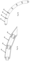
Figures 4a and 4b illustrate a first embodiment of the present invention using the same schematic method of illustration. Theend section 45 is connected to anequipment wall 10. Apipe section 48 is connected to theend section 45 with aclamp section 46. Theend section 45 comprises two outward extending flanges at the end extending from theequipment wall 10. Thepipe section 48 also comprises outward extendingend flanges 49 at each end thereof and at least an additional outward extendingflange 47. - The distance between each of the
end flange 49 and theadditional flange 47 on thepipe section 48 shall enable the inward facingflange 44 on theclamp section 46 to move freely within a calculated limitation. This calculated limitation of movement controls the angle between eachclamp section 46 and anadjacent clamp section 46 when the bend restrictor is locked into a rigid arc (seefigs. 6a and 6b ) and the calculated limitation is determined by the geometric relation between the diameter of the cable, the wall thickness of thepipe section 48, the height of theflange 49 on thepipe section 48, the thickness of theflange 44 of theclamp section 46, the angle between twoadjacent clamp sections 46. - The distance between the outward extending
end flange 49 and theadditional flange 47 on thepipe 48 may be determined by the following equation and is illustrated onfigure 6c : - CD: 61 : Cable diameter including clearance towards the inside of the
pipe section 48 - PWT: 62 : Wall thickness of the
pipe section 48 - PFH: 63 : Height of the outward extending
pipe end flange 49 of thepipe section 48 - CFT: 64 : Thickness of the inward facing
flange 44 of theclamp section 46 - ABC: 65 : Angle between the central axis of the
pipe section 48 and the central axis of theadjacent clamp section 46 - DBPF: 66 : Distance Between two Pipe Flanges (between an
end flange 49 and an adjacent additional flange 47)
- In addition, the locking radius characterizes the maximum bending of the cable allowed by the bend restrictor. In other words, when bent, a cable protected by the bend restrictor cannot have a bending radius under the locking radius, which describes the radius of the rigid arc below which the bend restrictor cannot move.
- The locking radius may be determined by the following equation and is illustrated on
figures 6c and6d : - LR : 67 : Locking Radius, where bend restrictor is locked into a rigid arc
- TPF : 68 : Thickness of additional outward facing
pipe flange 47 - LC : 69 : Length of
Clamp section 46
- At each end the
clamp section 46 comprises an inward facingflange 44, 44'. The cable to be protected by the bend restrictor is not shown in the schematic representation, but the longitudinal open passage therethrough is easily visible. In the schematic illustration it is also not visible that each clamp section may be longitudinally split in at least two sections and each pipe section may be longitudinally split in at least two sections. In this embodiment, the pipe sections have a very limited contribution to the length of the bend restrictor. - If the bend restrictor is prepared in steel for installation in moist climate including submerged in water the parts have to be protected from corrosion to obtain a reasonable life span. For this purpose, sacrificial anodes may be installed on each part or element.
-
Figures 5a and 5b illustrate a second embodiment of the present invention using the same schematic method of illustration. Theend section 45 is connected to anequipment wall 10. Apipe section 58 is connected to theend section 45 with aclamp section 56. Theend section 45 comprises two outward extending flanges at the end extending from theequipment wall 10. Thepipe section 58 also comprises outward extendingend flanges 59 at each end thereof and two additional outward extendingflanges 57, at a certain distance from each of theadjacent end flanges 59, respectively. The distance between theend flange 59 and the adjacentadditional flange 57 on thepipe section 58 shall enable the inward facingflange 54 on theclamp section 56 to move freely within a calculated limitation, as explained for the first embodiment. - Each end of the
clamp section 56 comprises an inward facingflange 54, 54'. The cable to be protected by the bend restrictor is not shown in the schematic representation, but the longitudinal open passage therethrough is easily visible. In the schematic illustration it is also not visible that each clamp section may be longitudinally split in at least two sections and each pipe section may be longitudinally split in at least two sections. In this embodiment, the pipe sections have a very limited contribution to the length of the bend restrictor. -
Figures 6a, 6b and6c show a cross-sectional and a side views of a first alternative of a bend restrictor according to the first embodiment in further detail. In this illustration the bend restrictor is made of steel. A number ofpipe sections 48 are connected withclamp sections 46 arranged therebetween. In this first alternative, theclamp sections 46 are a continuous cylinder. The assembly is much faster than in the prior art, especially due to the small size and weight of thepipe sections 48. -
Figures 7a and 7b show a cross-sectional and a side views of a bend restrictor according to the second embodiment in further detail. In this illustration the bend restrictor is made of steel. A number ofpipe sections 48 are connected withclamp sections 46 arranged therebetween. In this alternative, theclamp sections 46 are made of a plurality of elongated elements, here cylinders (tubes or bars) between two discs at each end. In other words theclamp sections 46 feature at least one aperture (here a plurality of apertures) which results in a substantial reduction in weight of the clamp. This alternative further improves the assembly speed for the bend restrictor, combining the effect of the small size and weight of thepipe sections 48 and a lighter clamp section than in the first alternative shown infigures 6a and 6b which can lead to an even faster assembly.
Claims (14)
- Bend restrictor for restricting the bending of a cable comprising at least one pipe section (48,58) and at least one clamp section (46, 56)- wherein each pipe section (48,58) comprises an outward facing end flange (49,59) at each end, and at least an additional outward facing flange (47,57) arranged between the end flanges (49,59),- wherein the clamp section (46, 56) comprises an inward facing flange (44, 44', 54, 54') at each end, and a pipe shaped middle section therebetween,wherein the distance between each of the outward facing end flanges (49,59) and the additional outward facing flange (47,57) of the pipe section (48,58) is adapted to receive the inward facing flange (44, 44', 54, 54') of the clamp section (46, 56).
- Bend restrictor according to claim 1, wherein the locking radius of the bend restrictor is equal to or over the minimum allowable bending radius of the cable.
- Bend restrictor according to any of the preceding claims, wherein the distance between the outward facing end flange (49,59) and the adjacent additional outward facing flange (47,57) of the pipe section (48,58) is larger than the width of the inward facing flange (44, 44', 54, 54') of the clamp section (46, 56), so that the axis of the pipe section and the axis of the adjacent clamp section can have an inclination relative to each other.
- Bend restrictor according to any of the preceding claims, wherein the distance between the outward facing end flange (49,59) and the adjacent additional outward facing flange (47,57) of the pipe section (48,58) is larger than the width of the inward facing flange (44, 44', 54, 54') of the clamp section (46, 56), so that a position of the central axis of the pipe section to the central axis of adjacent clamp section can vary between a first and second positions, wherein in the first position the axes are aligned and in the second position the axes are inclined relative to each other.
- Bend restrictor according to any of the preceding claims, wherein a maximum angle between adjacent clamp (46,56) and pipe sections (48,58) is comprised between 1.5 and 9 degrees wherein the angle is measured between the central axis of the pipe section (48,58) and the central axis of the adjacent clamp section (46,56).
- Bend restrictor according to any of the preceding claims, wherein the pipe section (48,58) comprises an outward facing flange (49,59) at each end, and at least two additional outward facing flanges (47,57) arranged between the end flanges (49,59).
- Bend restrictor according to any of the preceding claims, wherein the pipe section (48,58) is split in the longitudinal direction into at least two parts.
- Bend restrictor according to claim 7, wherein the at least two parts of the pipe section (48,58) are connectable through bolt connections, or through locking pin connections or through straps.
- Bend restrictor according to any of the preceding claims, wherein the clamp section (46, 56) is split in the longitudinal direction into at least two parts.
- Bend restrictor according to claim 9, wherein the at least two parts of the clamp section (46,56) are connectable through bolt connections, or through locking pin connections or through straps.
- Bend restrictor according to any of the preceding claims, wherein the clamp section (46, 56) is made of a rigid material.
- Bend restrictor according to any of the preceding claims, wherein the clamp section (46, 56) comprises a structural steel, a polymer or a fibre-reinforced polymer material.
- Bend restrictor according to any of the preceding claims, wherein the pipe shaped middle section of the clamp section (46, 56) features at least one aperture.
- Bend restrictor according to any of the preceding claims, wherein the pipe shaped middle section of the clamp section (46, 56) comprises a plurality of elongated elements extending between the two inward facing flanges (44, 44', 54, 54').
Priority Applications (2)
| Application Number | Priority Date | Filing Date | Title |
|---|---|---|---|
| EP22306918.8A EP4386175A1 (en) | 2022-12-16 | 2022-12-16 | Bend restrictor |
| US18/543,358 US20240426411A1 (en) | 2022-12-16 | 2023-12-18 | Bend restrictor |
Applications Claiming Priority (1)
| Application Number | Priority Date | Filing Date | Title |
|---|---|---|---|
| EP22306918.8A EP4386175A1 (en) | 2022-12-16 | 2022-12-16 | Bend restrictor |
Publications (1)
| Publication Number | Publication Date |
|---|---|
| EP4386175A1 true EP4386175A1 (en) | 2024-06-19 |
Family
ID=84901615
Family Applications (1)
| Application Number | Title | Priority Date | Filing Date |
|---|---|---|---|
| EP22306918.8A Pending EP4386175A1 (en) | 2022-12-16 | 2022-12-16 | Bend restrictor |
Country Status (2)
| Country | Link |
|---|---|
| US (1) | US20240426411A1 (en) |
| EP (1) | EP4386175A1 (en) |
Cited By (1)
| Publication number | Priority date | Publication date | Assignee | Title |
|---|---|---|---|---|
| USD1139430S1 (en) * | 2024-01-22 | 2026-08-04 | Ugreen Group Limited | Display screen or portion thereof with graphical user interface |
Citations (3)
| Publication number | Priority date | Publication date | Assignee | Title |
|---|---|---|---|---|
| FR2889557A1 (en) * | 2005-08-04 | 2007-02-09 | Technip France Sa | UNDERWATER EQUIPPED WITH FLEXIBLE CONTROLLED CURVED DRIVING |
| CN206889963U (en) * | 2017-06-28 | 2018-01-16 | 河海大学 | Based on the flexible pipe bending restrictor for improving section |
| EP3564569A1 (en) | 2018-05-03 | 2019-11-06 | Nexans | Bending restrictor |
Family Cites Families (4)
| Publication number | Priority date | Publication date | Assignee | Title |
|---|---|---|---|---|
| US3813744A (en) * | 1972-12-08 | 1974-06-04 | Seismic Logs | Geophone treatment |
| US5197767A (en) * | 1985-04-09 | 1993-03-30 | Tsubakimoto Chain Co. | Flexible supporting sheath for cables and the like |
| US9163463B2 (en) * | 2011-06-01 | 2015-10-20 | Deep Down, Inc. | Bend limiting stiffener and related methods |
| GB201400374D0 (en) * | 2014-01-09 | 2014-02-26 | Trelleborg Offshore U K Ltd | Interface |
-
2022
- 2022-12-16 EP EP22306918.8A patent/EP4386175A1/en active Pending
-
2023
- 2023-12-18 US US18/543,358 patent/US20240426411A1/en active Pending
Patent Citations (3)
| Publication number | Priority date | Publication date | Assignee | Title |
|---|---|---|---|---|
| FR2889557A1 (en) * | 2005-08-04 | 2007-02-09 | Technip France Sa | UNDERWATER EQUIPPED WITH FLEXIBLE CONTROLLED CURVED DRIVING |
| CN206889963U (en) * | 2017-06-28 | 2018-01-16 | 河海大学 | Based on the flexible pipe bending restrictor for improving section |
| EP3564569A1 (en) | 2018-05-03 | 2019-11-06 | Nexans | Bending restrictor |
Cited By (1)
| Publication number | Priority date | Publication date | Assignee | Title |
|---|---|---|---|---|
| USD1139430S1 (en) * | 2024-01-22 | 2026-08-04 | Ugreen Group Limited | Display screen or portion thereof with graphical user interface |
Also Published As
| Publication number | Publication date |
|---|---|
| US20240426411A1 (en) | 2024-12-26 |
Similar Documents
| Publication | Publication Date | Title |
|---|---|---|
| EP3564569B1 (en) | Bending restrictor | |
| CN100406795C (en) | A fixing mechanism for pipe fittings | |
| KR20140123948A (en) | Bend restriction element for restricting the bending range of a conduit | |
| US7631384B2 (en) | Device for damping vibrations of a guy-cable array for an engineering construction and corresponding damping method | |
| US20220214004A1 (en) | Split segmented bend restrictor | |
| US9188266B2 (en) | Protective sleeve for a flexible pipe | |
| AU2008211995A1 (en) | Flexible hang-off arrangement for a catenary riser | |
| SE467018B (en) | PIPE CONNECTION WITH A TENSIVE CLAMP FOR FIXING OF UNPROFILED PIPES | |
| DK2953220T3 (en) | Protective device for laying submarine cables | |
| US20240426411A1 (en) | Bend restrictor | |
| CN112970158B (en) | Bending limiter | |
| CN115917112B (en) | clamps and clamps | |
| US20170107770A1 (en) | Interface | |
| GB2142788A (en) | Bend limiter for cables | |
| EP2395249A1 (en) | Segmented thread and connecting arrangement | |
| WO2017027129A1 (en) | Bending restrictor assembly for a pipeline | |
| US11142288B2 (en) | Bending strain relief assembly for marine cables incorporating at least one elongated stiffness member | |
| GB2186658A (en) | Flexible elongate tubular article | |
| US20070079969A1 (en) | Segmented steel tube bundle termination assembly | |
| CN100572887C (en) | Balanced curved pipe joint with large displacement compensation capability | |
| CA1037989A (en) | Flexible pipe connector | |
| WO2002057560A1 (en) | End termination of tension leg | |
| JP7599950B2 (en) | Mooring coupler | |
| JP7014034B2 (en) | Long body bending inhibitor | |
| WO2017064262A1 (en) | Clamping device, configured to be secured around a line, related assembly and method |
Legal Events
| Date | Code | Title | Description |
|---|---|---|---|
| PUAI | Public reference made under article 153(3) epc to a published international application that has entered the european phase |
Free format text: ORIGINAL CODE: 0009012 |
|
| STAA | Information on the status of an ep patent application or granted ep patent |
Free format text: STATUS: THE APPLICATION HAS BEEN PUBLISHED |
|
| AK | Designated contracting states |
Kind code of ref document: A1 Designated state(s): AL AT BE BG CH CY CZ DE DK EE ES FI FR GB GR HR HU IE IS IT LI LT LU LV MC ME MK MT NL NO PL PT RO RS SE SI SK SM TR |
|
| STAA | Information on the status of an ep patent application or granted ep patent |
Free format text: STATUS: REQUEST FOR EXAMINATION WAS MADE |
|
| 17P | Request for examination filed |
Effective date: 20241219 |
|
| STAA | Information on the status of an ep patent application or granted ep patent |
Free format text: STATUS: EXAMINATION IS IN PROGRESS |
|
| 17Q | First examination report despatched |
Effective date: 20260217 |