EP4386174A1 - Rotating sleeve, rock drilling machine and method - Google Patents
Rotating sleeve, rock drilling machine and method Download PDFInfo
- Publication number
- EP4386174A1 EP4386174A1 EP22213130.2A EP22213130A EP4386174A1 EP 4386174 A1 EP4386174 A1 EP 4386174A1 EP 22213130 A EP22213130 A EP 22213130A EP 4386174 A1 EP4386174 A1 EP 4386174A1
- Authority
- EP
- European Patent Office
- Prior art keywords
- rotating sleeve
- internal teeth
- shank adapter
- teeth
- sleeve
- Prior art date
- Legal status (The legal status is an assumption and is not a legal conclusion. Google has not performed a legal analysis and makes no representation as to the accuracy of the status listed.)
- Granted
Links
Images




Classifications
-
- E—FIXED CONSTRUCTIONS
- E21—EARTH OR ROCK DRILLING; MINING
- E21B—EARTH OR ROCK DRILLING; OBTAINING OIL, GAS, WATER, SOLUBLE OR MELTABLE MATERIALS OR A SLURRY OF MINERALS FROM WELLS
- E21B6/00—Drives for drilling with combined rotary and percussive action
-
- B—PERFORMING OPERATIONS; TRANSPORTING
- B25—HAND TOOLS; PORTABLE POWER-DRIVEN TOOLS; MANIPULATORS
- B25D—PERCUSSIVE TOOLS
- B25D17/00—Details of, or accessories for, portable power-driven percussive tools
- B25D17/005—Attachments or adapters placed between tool and hammer
-
- B—PERFORMING OPERATIONS; TRANSPORTING
- B25—HAND TOOLS; PORTABLE POWER-DRIVEN TOOLS; MANIPULATORS
- B25D—PERCUSSIVE TOOLS
- B25D17/00—Details of, or accessories for, portable power-driven percussive tools
- B25D17/08—Means for retaining and guiding the tool bit, e.g. chucks allowing axial oscillation of the tool bit
- B25D17/084—Rotating chucks or sockets
-
- E—FIXED CONSTRUCTIONS
- E21—EARTH OR ROCK DRILLING; MINING
- E21B—EARTH OR ROCK DRILLING; OBTAINING OIL, GAS, WATER, SOLUBLE OR MELTABLE MATERIALS OR A SLURRY OF MINERALS FROM WELLS
- E21B7/00—Special methods or apparatus for drilling
- E21B7/02—Drilling rigs characterised by means for land transport with their own drive, e.g. skid mounting or wheel mounting
- E21B7/025—Rock drills, i.e. jumbo drills
Definitions
- the invention relates to a rotating sleeve of a rock drilling machine.
- the rotating sleeve is mountable around a shank adapter and is intended for transmitting rotation torque between a rotation device and the shank adapter.
- the invention further relates to a rock drilling machine and to a method of manufacturing a rotating sleeve of a rock drilling machine.
- the rock drilling rigs are provided with one or more booms and rock drilling machines are arranged at distal ends of the booms.
- the rock drilling machine comprises an impact device provided with an impact piston which is configured to provide a drilling tool with impact pulses via a shank adapter.
- the shank adapter is configured to transmit impact pulses and torque from the rock drilling machine to the drilling tool.
- Around the shank adapter is a rotating sleeve which is rotated by a rotation device.
- the rotating sleeve comprises several internal teeth which match with teeth or splines of the shank adapter.
- the internal teeth are subjected to high stresses during the rotation. In known constructions some disadvantages have been detected in the rotating sleeves and especially regarding durability of their internal teeth.
- An object of the invention is to provide a novel and improved rotating sleeve, a rock drilling machine equipped with such rotating sleeve, and a method for manufacturing a rotating sleeve of a rock drilling machine.
- the rotating sleeve according to the invention is characterized by the characterizing features of the first independent apparatus claim.
- the rock drilling machine according to the invention is characterized by the characterizing features of the second independent apparatus claim.
- the method according to the invention is characterized by the characterizing features of the independent method claim.
- a rotating sleeve which is mountable around a shank adapter of a rock drilling machine, comprises several internal teeth provided with opposing first flank surfaces and second flank surfaces for transmitting rotation to the shank adapter.
- the internal teeth have end surfaces at longitudinal ends of the teeth. Further, the teeth are provided with at least first end reliefs comprising first chamfers between the first flank surfaces and the end surfaces.
- each internal tooth of the rotating sleeve is provided with one or more end reliefs wherein sharp edges between the flank surfaces and the end surfaces are beveled or chamfered.
- the teeth may have the end reliefs at one end or at both ends.
- An advantage of the disclosed solution is that loadings directed to the end portions of the teeth can be decreased due to the end reliefs. This way material breaks at the end portions of the internal teeth can be avoided and durability of the rotating sleeve can be improved. Then, service intervals may be longer and effective drilling process can be ensured. Further, the solution allows use of greater torques when the risks for tooth end breaks can be solved.
- the internal teeth are spur teeth i.e., the teeth are straight.
- the internal teeth having straight, and elongated configuration are easy to produce, and they allow axial movement between the rotating sleeve and the shank adapter during the use.
- the internal teeth are alternatively obliquely toothed teeth or twisted teeth i.e., the teeth are not straight.
- length of the rotating sleeve is greater than diameter of the rotating sleeve, whereby the teeth are relatively long in axial direction.
- length of the rotating sleeve is multiple in relation to diameter of the rotating sleeve.
- the mentioned first flank surfaces are configured to transmit rotation when the shank is turned in drilling direction
- the mentioned second flank surfaces are configured to transmit rotation when the shank is turned in reverse direction
- the end reliefs have planar surfaces.
- the chamfers between the first flank surfaces and the end surfaces are planar. Then the chamfers have as simple surface shape as possible to be manufactured.
- the end reliefs have alternatively curved surfaces.
- the sharp edges between the first flank surfaces and the end surfaces are rounded.
- the teeth are provided with second end reliefs comprising second chamfers between the second flank surfaces and the end surfaces.
- all four sharp corners of the tooth are chamfered to provide the four end reliefs for the tooth.
- the teeth are provided with end reliefs only at one end of the teeth.
- corners of each tooth are chamfered either at a front or rear end of each tooth.
- the end reliefs can be formed for example to that end which is subjected to greater loadings.
- the teeth are provided with first or second end reliefs only at one end of the teeth. All different combinations for placing the end reliefs are possible.
- the rotating sleeve comprises an inner first sleeve component and an outer second sleeve component arrangeable inside one another, and wherein the inner first sleeve comprises the internal teeth provided with the end reliefs.
- the rotating sleeve has two-part configuration wherein rotation torque is transmitted on an outer surface of the outer second sleeve component and wherein between the inner first sleeve component and the outer second sleeve component is a gear system for transmitting the torque between the sleeve components.
- the inner first sleeve component is a changeable wearing component.
- the inner first sleeve component is made of bronze or corresponding slide bearing material.
- the rotating sleeve has single piece configuration. Then, the rotating sleeve comprises internal teeth with the end reliefs, and external teeth for receiving torque from a rotation device.
- the rotating sleeve has external teeth for receiving torque from a rotation device either directly (one piece structure) or indirectly (via an outer second sleeve component).
- each first flank surface comprises lubricating grooves.
- each first flank surface has one axial lubricating groove for providing lubricant to contact surfaces between splines of the shank adapter and the first flank surfaces of the rotating sleeve.
- depth and width of the mentioned lubricant groove are both at least 2 mm.
- depth of the lubricant groove is 2 - 4 mm.
- both ends of the lubricant groove are open to the end reliefs.
- the lubricant groove has no closed ends but instead extends end to end of the tooth.
- the end reliefs protect well from high loadings areas surrounding the lubricant grooves at the end portions of the teeth.
- flank surfaces are without lubricating grooves.
- the lubricating may be based on air-oil mist, for example.
- length of the end relief is 8 - 14% of total length of the internal tooth.
- transverse dimension of the end relief is 10 - 16% of distance between two opposing parallel flank surfaces.
- an angle between a surface of the end relief and longitudinal axis of the internal tooth is 9 - 16°.
- shape of the end relief corresponds to a truncated triangle.
- the end reliefs are formed by means of a wire cutting method based on electrical discharge machining (EDM).
- EDM electrical discharge machining
- the end reliefs are manufactured by a wire EDM or spark machining techniques.
- the end reliefs are formed by means of a chip removal milling tool.
- the disclosed solution relates to a rock drilling machine, comprising: a body; an impact device for generating impact pulses; a shank adapter for receiving the impact pulses and transmitting them as stress waves to a drilling tool connectable to the shank adapter; a rotation device for turning the shank adapter around its longitudinal axis; and a rotating sleeve surrounding the shank adapter and transmitting torque from the rotation device to the shank adapter.
- the rotating sleeve is in accordance with any one of the features and embodiments disclosed in this document.
- the disclosed solution relates to a method of manufacturing a rotating sleeve of a rock drilling machine, and wherein the rotating sleeve is mountable around a shank adapter for transmitting torque between a rotation device and the shank adapter.
- the method comprises: providing the rotating sleeve with several internal teeth wherein the internal teeth comprise first flank surfaces and second flank surfaces; and providing the internal teeth with end surfaces at longitudinal ends of the teeth.
- the method further comprises chamfering edges between the first flank surfaces and the end surfaces of the teeth for providing the teeth with end reliefs. The end reliefs protect the teeth ends form breakages caused by excessive loadings.
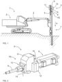
- FIG. 1 shows a rock drilling rig 1 intended for surface drilling.
- the rock drilling rig 1 comprises a movable carrier 2 and at least one drilling boom 3 connected to the carrier 2.
- a drilling unit 4 provided with a feed beam 5 and a rock drilling machine 6 supported on it.
- a drilling tool 7 is connectable to the drilling machine 6.
- the rock drilling machine 6 comprises a shank adaptor 8 at a front end FE of the rock drilling machine 6 for connecting the tool 7.
- the rock drilling machine 6 further comprises an impact device 9 and a rotating device 10.
- the rock drilling machine 6 may be moved towards a drilling direction A on the feed beam 5 by means of a feed device 11.
- Figure 2 discloses a rock drilling machine 6 comprising a body 12, an impact device 9, a rotating device 10 and a gear housing G. Mounted at a front end FE of the gear housing G are a flushing housing 13 and a shank adaptor 8. Flushing agent, such as water, is conveyed by means of a flushing channel 14 to the flushing housing 13 or flushing head.
- Figure 3 discloses a gear housing G of a rock drilling machine 6.
- An impact surface 15 of a shank adapter 8 receives impact pulses from a percussion piston 16 and rotation torque is transmitted to the shank adapter 8 by means of a rotating sleeve 17.
- the rotating sleeve 17 is rotated by a rotating device 10 coupled to the rotating sleeve 17 by means of gears 18.
- the rotating sleeve 17 may be a single piece transmission element or it may comprise two components shown in Figure 3 .
- the two-piece configuration may comprise an inner first rotating sleeve component 17a and an outer second rotating sleeve component 17b between which there are gears 19.
- a rear most end part of the shank adapter 8 may be surrounded by means of a shank sleeve 20 for transmitting axial forces in drilling direction A and in opposite reverse direction for the shank adapter 8.
- the shank adapter 8 comprises splines 21 or corresponding teeth which are in contact with internal teeth 22 of the rotating sleeve 17.
- Flank surfaces of the internal teeth 22 may comprise lubricating grooves 23 for gear contact between the rotating sleeve 17 and the shank adapter 8.
- the lubricating groves 23 may be open at both ends and lubricating oil may be directed to the groove through lubricating channels 24.
- flows of lubricating medium are shown by arrows as well as different lubricating channels and routes. Some examples of the routes are marked by means of reference numerals 25, 26.
- FIG. 4 discloses a shank adapter 8 wherein a coupling head 27 comprises a shoulder 28 and a connecting thread 29. Alternative coupling end arrangements may also be implemented.
- a rear end 30 of the shank adapter 8 may be a portion for receiving impact pulses IP and provided with an impact surface 15.
- a middle section 31 is an opening 32 for leading flushing fluid inside the shank adapter and to a drilling tool 7.
- Figure 5 discloses a rotating sleeve 17 inside which a shank adapter of a rock drilling machine can be mounted.
- the rotating sleeve 17 comprises several internal teeth 22 provided with opposing first flank surfaces 32 and second flank surfaces 33 for transmitting rotation to the shank adapter.
- the internal teeth 22 have end surfaces 34 at longitudinal ends of the teeth.
- the rotating sleeve 22 can be rotated in direction R during normal drilling and in reverse direction by means of a rotation device.
- the external teeth 22 may form the gear 19 shown in the previous Figure 3 .
- the external tooth 35 may be located at a front end part 36 of the rotating sleeve 17 and the rear end part 37 may be without the gears.
- Figure 5 further shows that the internal teeth 22 are provided with end reliefs 38, 39 between the end surfaces 34 and the flank surfaces 32, 33.
- Figure 6 shows one internal tooth 22 of the rotating sleeve in detailed
- Figure 7 shows the same rotating sleeve 17 in a different view direction
- Figure 8 is a cross-sectional view of the same structure.
- Figures 5 - 8 show that the first flank surfaces 32 of the internal teeth 22 comprise lubricating grooves 23.
- the lubricating grooves 23 can extend end to end of the internal teeth. Thereby, both ends of the lubricant groove are open to the first end reliefs 38, 39.
- Figure 5 further discloses that an angle K between a surface of the end relief 38, 39 and longitudinal axis of the internal tooth 22 is 9 - 16°.
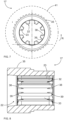
- Figure 7 shows the rotating sleeve 17 axially and seen from its end direction.
- the rotating sleeves disclosed in Figures 5 , 7 , 8 , 9 and 11 - 13 may be inner rotating sleeve components 17a shown in Figure 3 and around which outer rotating sleeve components may be arranged.
- a rotating sleeve arrangement may comprise the inner first sleeve component and the outer second sleeve component arrangeable inside one another.
- reference 41 indicates by means of broken lines the surrounding outer second sleeve component.
- the inner first sleeve comprises the internal teeth provided with the end reliefs and between the sleeve components are teeth or other transmission elements for transmitting torque between the sleeve components.
- rotating torque is transmitted directly on one-piece rotating sleeve comprising internal and external teeth and end reliefs on internal teeth.
- Figures 9 and 10 show that internal teeth 22 of a rotating sleeve 17 are provided with first end reliefs 38 only. Thus, in this rotating sleeve 17 ends of the internal teeth 22 are protected against high loadings in normal rotation direction R only. Further, only first flank surfaces 32 of the internal teeth are provided with lubricating grooves 23. In reverse rotation direction loadings are minor wherefore the end reliefs and the lubricating grooves are not necessarily needed on opposing second flank surfaces 33.
- the end reliefs 38 of the internal teeth 22 shown in Figures 9 and 10 are produced by milling technique, wherefore some additional marks 42 produced by a chip removing tool can be seen on inner surface of the rotating sleeve 17.
- the end reliefs 38, 39 are manufactured by means of a wire cutting method based on electrical discharge machining no such markings exist, which is apparent when examining Figures 5 - 8 .
- Figure 11 discloses a rotating sleeve 17 which differs from the previously shown rotating sleeves in that there are no lubricating grooves on flank surfaces 32, 33 of the internal teeth 22.
- the internal teeth 22 are provided with end reliefs 38, 39 at their both ends.
- Figure 12 discloses a rotating sleeve 17 comprising end reliefs 38, 39 only at rear ends of internal teeth 22. Further, flank surfaces 32, 33 of the internal teeth are without lubricating grooves.
- Figure 13 discloses similar features as the previous Figure 5 but shows more clearly that ends of internal teeth 22 can be provided with the end reliefs 38, 39.
Landscapes
- Engineering & Computer Science (AREA)
- Life Sciences & Earth Sciences (AREA)
- Geology (AREA)
- Mining & Mineral Resources (AREA)
- Mechanical Engineering (AREA)
- Physics & Mathematics (AREA)
- Environmental & Geological Engineering (AREA)
- Fluid Mechanics (AREA)
- General Life Sciences & Earth Sciences (AREA)
- Geochemistry & Mineralogy (AREA)
- Earth Drilling (AREA)
Abstract
Description
- The invention relates to a rotating sleeve of a rock drilling machine. The rotating sleeve is mountable around a shank adapter and is intended for transmitting rotation torque between a rotation device and the shank adapter.
- The invention further relates to a rock drilling machine and to a method of manufacturing a rotating sleeve of a rock drilling machine.
- The field of the invention is defined more specifically in the preambles of the independent claims.
- In mines and at other work sites different type of rock drilling rigs are used. The rock drilling rigs are provided with one or more booms and rock drilling machines are arranged at distal ends of the booms. The rock drilling machine comprises an impact device provided with an impact piston which is configured to provide a drilling tool with impact pulses via a shank adapter. The shank adapter is configured to transmit impact pulses and torque from the rock drilling machine to the drilling tool. Around the shank adapter is a rotating sleeve which is rotated by a rotation device. The rotating sleeve comprises several internal teeth which match with teeth or splines of the shank adapter. The internal teeth are subjected to high stresses during the rotation. In known constructions some disadvantages have been detected in the rotating sleeves and especially regarding durability of their internal teeth.
- An object of the invention is to provide a novel and improved rotating sleeve, a rock drilling machine equipped with such rotating sleeve, and a method for manufacturing a rotating sleeve of a rock drilling machine.
- The rotating sleeve according to the invention is characterized by the characterizing features of the first independent apparatus claim.
- The rock drilling machine according to the invention is characterized by the characterizing features of the second independent apparatus claim.
- The method according to the invention is characterized by the characterizing features of the independent method claim.
- An idea of the disclosed solution is that a rotating sleeve, which is mountable around a shank adapter of a rock drilling machine, comprises several internal teeth provided with opposing first flank surfaces and second flank surfaces for transmitting rotation to the shank adapter. The internal teeth have end surfaces at longitudinal ends of the teeth. Further, the teeth are provided with at least first end reliefs comprising first chamfers between the first flank surfaces and the end surfaces.
- In other words, each internal tooth of the rotating sleeve is provided with one or more end reliefs wherein sharp edges between the flank surfaces and the end surfaces are beveled or chamfered. The teeth may have the end reliefs at one end or at both ends.
- An advantage of the disclosed solution is that loadings directed to the end portions of the teeth can be decreased due to the end reliefs. This way material breaks at the end portions of the internal teeth can be avoided and durability of the rotating sleeve can be improved. Then, service intervals may be longer and effective drilling process can be ensured. Further, the solution allows use of greater torques when the risks for tooth end breaks can be solved.
- According to an embodiment, the internal teeth are spur teeth i.e., the teeth are straight. The internal teeth having straight, and elongated configuration are easy to produce, and they allow axial movement between the rotating sleeve and the shank adapter during the use.
- According to an embodiment, the internal teeth are alternatively obliquely toothed teeth or twisted teeth i.e., the teeth are not straight.
- According to an embodiment, length of the rotating sleeve is greater than diameter of the rotating sleeve, whereby the teeth are relatively long in axial direction.
- According to an embodiment, length of the rotating sleeve is multiple in relation to diameter of the rotating sleeve.
- According to an embodiment, the mentioned first flank surfaces are configured to transmit rotation when the shank is turned in drilling direction, and the mentioned second flank surfaces are configured to transmit rotation when the shank is turned in reverse direction.
- According to an embodiment, the end reliefs have planar surfaces. In other words, the chamfers between the first flank surfaces and the end surfaces are planar. Then the chamfers have as simple surface shape as possible to be manufactured.
- According to an embodiment, the end reliefs have alternatively curved surfaces. In other words, the sharp edges between the first flank surfaces and the end surfaces are rounded.
- According to an embodiment, the teeth are provided with second end reliefs comprising second chamfers between the second flank surfaces and the end surfaces. In other words, all four sharp corners of the tooth are chamfered to provide the four end reliefs for the tooth. An advantage of this embodiment is that the teeth ends are protected against loadings also in the direction of the reverse rotation.
- According to an embodiment, the teeth are provided with end reliefs only at one end of the teeth. In other words, corners of each tooth are chamfered either at a front or rear end of each tooth. The end reliefs can be formed for example to that end which is subjected to greater loadings. In a further embodiment, the teeth are provided with first or second end reliefs only at one end of the teeth. All different combinations for placing the end reliefs are possible.
- According to an embodiment, the rotating sleeve comprises an inner first sleeve component and an outer second sleeve component arrangeable inside one another, and wherein the inner first sleeve comprises the internal teeth provided with the end reliefs. In other words, the rotating sleeve has two-part configuration wherein rotation torque is transmitted on an outer surface of the outer second sleeve component and wherein between the inner first sleeve component and the outer second sleeve component is a gear system for transmitting the torque between the sleeve components.
- According to an embodiment, the inner first sleeve component is a changeable wearing component.
- According to an embodiment, the inner first sleeve component is made of bronze or corresponding slide bearing material.
- According to an alternative embodiment, the rotating sleeve has single piece configuration. Then, the rotating sleeve comprises internal teeth with the end reliefs, and external teeth for receiving torque from a rotation device.
- According to an embodiment, the rotating sleeve has external teeth for receiving torque from a rotation device either directly (one piece structure) or indirectly (via an outer second sleeve component).
- According to an embodiment, at least the first flank surfaces comprise lubricating grooves. In other words, each first flank surface has one axial lubricating groove for providing lubricant to contact surfaces between splines of the shank adapter and the first flank surfaces of the rotating sleeve.
- According to an embodiment, depth and width of the mentioned lubricant groove are both at least 2 mm.
- According to an embodiment, depth of the lubricant groove is 2 - 4 mm.
- According to an embodiment, both ends of the lubricant groove are open to the end reliefs. In other words, the lubricant groove has no closed ends but instead extends end to end of the tooth. In constructions where the lubricant grooves extend for the entire length of the internal teeth, the end reliefs protect well from high loadings areas surrounding the lubricant grooves at the end portions of the teeth.
- According to an embodiment, the flank surfaces are without lubricating grooves. Then the lubricating may be based on air-oil mist, for example.
- According to an embodiment, length of the end relief is 8 - 14% of total length of the internal tooth.
- According to an embodiment, transverse dimension of the end relief is 10 - 16% of distance between two opposing parallel flank surfaces.
- According to an embodiment, an angle between a surface of the end relief and longitudinal axis of the internal tooth is 9 - 16°.
- According to an embodiment, shape of the end relief corresponds to a truncated triangle.
- According to an embodiment, the end reliefs are formed by means of a wire cutting method based on electrical discharge machining (EDM). In other words, the end reliefs are manufactured by a wire EDM or spark machining techniques.
- According to an alternative solution the end reliefs are formed by means of a chip removal milling tool.
- According to an embodiment, the disclosed solution relates to a rock drilling machine, comprising: a body; an impact device for generating impact pulses; a shank adapter for receiving the impact pulses and transmitting them as stress waves to a drilling tool connectable to the shank adapter; a rotation device for turning the shank adapter around its longitudinal axis; and a rotating sleeve surrounding the shank adapter and transmitting torque from the rotation device to the shank adapter. Further, the rotating sleeve is in accordance with any one of the features and embodiments disclosed in this document.
- According to an embodiment, the disclosed solution relates to a method of manufacturing a rotating sleeve of a rock drilling machine, and wherein the rotating sleeve is mountable around a shank adapter for transmitting torque between a rotation device and the shank adapter. The method comprises: providing the rotating sleeve with several internal teeth wherein the internal teeth comprise first flank surfaces and second flank surfaces; and providing the internal teeth with end surfaces at longitudinal ends of the teeth. The method further comprises chamfering edges between the first flank surfaces and the end surfaces of the teeth for providing the teeth with end reliefs. The end reliefs protect the teeth ends form breakages caused by excessive loadings.
- The above disclosed embodiments may be combined to form suitable solutions having those of the above features that are needed.
- Some embodiments are described in more detail in the accompanying drawings, in which
-
Figure 1 is a schematic side view of a rock drilling rig for surface drilling, -
Figure 2 is a schematic view of a hydraulic rock drilling machine, -
Figure 3 is a schematic and cross-sectional side view of a front part of a rock drilling machine, -
Figure 4 is a schematic side view of a shank adapter provided with splines at a rear end for receiving rotating torque, -
Figure 5 is a schematic view of a rotating sleeve inside which a shank adapter with splines can be arranged, -
Figure 6 is a schematic view of an internal tooth of a rotating sleeve seen in axial direction of the rotating sleeve, -
Figure 7 is a schematic and axial view of the rotating sleeve shown inFigure 5 , -
Figure 8 is a schematic and cross sectional side view of the rotating sleeve shown inFigures 5 and7 , -
Figure 9 is a schematic view of a rotating sleeve provided with internal teeth with milled end reliefs, -
Figure 10 is a schematic view of a milled internal tooth of a rotating sleeve seen in axial direction of the rotating sleeve, -
Figure 11 is a schematic view of a rotating sleeve provided with internal teeth without lubricating grooves, -
Figure 12 is a schematic view of a rotating sleeve provided with end reliefs only at rear ends of internal teeth of the sleeve, and -
Figure 13 is a schematic view of a rotating sleeve provided with end reliefs at both ends of internal teeth of the sleeve. - For the sake of clarity, the figures show some embodiments of the disclosed solution in a simplified manner. In the figures, like reference numerals identify like elements.
-
Figure 1 shows arock drilling rig 1 intended for surface drilling. Therock drilling rig 1 comprises amovable carrier 2 and at least onedrilling boom 3 connected to thecarrier 2. At a distal end portion of thedrilling boom 3 is adrilling unit 4 provided with afeed beam 5 and arock drilling machine 6 supported on it. Adrilling tool 7 is connectable to thedrilling machine 6. Therock drilling machine 6 comprises ashank adaptor 8 at a front end FE of therock drilling machine 6 for connecting thetool 7. Therock drilling machine 6 further comprises animpact device 9 and arotating device 10. Therock drilling machine 6 may be moved towards a drilling direction A on thefeed beam 5 by means of afeed device 11. During the drilling impact pulses are generated by means of the impact device to therotating shank adapter 8 which transmits the impact pulses and torque to thedrilling tool 7. Flushing agent flow is conveyed through a hollow structure to theshank adapter 8 and all the way through thedrilling tool 7 to a bottom of the drilled hole for flushing drilling cuttings away from the drilled hole. -
Figure 2 discloses arock drilling machine 6 comprising abody 12, animpact device 9, arotating device 10 and a gear housing G. Mounted at a front end FE of the gear housing G are a flushinghousing 13 and ashank adaptor 8. Flushing agent, such as water, is conveyed by means of a flushingchannel 14 to the flushinghousing 13 or flushing head. -
Figure 3 discloses a gear housing G of arock drilling machine 6. Animpact surface 15 of ashank adapter 8 receives impact pulses from apercussion piston 16 and rotation torque is transmitted to theshank adapter 8 by means of arotating sleeve 17. Therotating sleeve 17 is rotated by arotating device 10 coupled to therotating sleeve 17 by means ofgears 18. Therotating sleeve 17 may be a single piece transmission element or it may comprise two components shown inFigure 3 . The two-piece configuration may comprise an inner firstrotating sleeve component 17a and an outer secondrotating sleeve component 17b between which there are gears 19. A rear most end part of theshank adapter 8 may be surrounded by means of ashank sleeve 20 for transmitting axial forces in drilling direction A and in opposite reverse direction for theshank adapter 8. Theshank adapter 8 comprisessplines 21 or corresponding teeth which are in contact withinternal teeth 22 of therotating sleeve 17. - Flank surfaces of the
internal teeth 22 may compriselubricating grooves 23 for gear contact between therotating sleeve 17 and theshank adapter 8. The lubricatinggroves 23 may be open at both ends and lubricating oil may be directed to the groove throughlubricating channels 24. InFigure 3 flows of lubricating medium are shown by arrows as well as different lubricating channels and routes. Some examples of the routes are marked by means ofreference numerals -
Figure 4 discloses ashank adapter 8 wherein acoupling head 27 comprises ashoulder 28 and a connectingthread 29. Alternative coupling end arrangements may also be implemented. At arear end 30 of theshank adapter 8 may be a portion for receiving impact pulses IP and provided with animpact surface 15. There are also splines 21 for transmitting rotation R for theshank adapter 8. At amiddle section 31 is anopening 32 for leading flushing fluid inside the shank adapter and to adrilling tool 7. -
Figure 5 discloses arotating sleeve 17 inside which a shank adapter of a rock drilling machine can be mounted. Therotating sleeve 17 comprises severalinternal teeth 22 provided with opposing first flank surfaces 32 and second flank surfaces 33 for transmitting rotation to the shank adapter. Theinternal teeth 22 haveend surfaces 34 at longitudinal ends of the teeth. Therotating sleeve 22 can be rotated in direction R during normal drilling and in reverse direction by means of a rotation device. On an outer surface of therotating sleeve 22 there areexternal teeth 35 for transmitting rotating torque to therotating sleeve 22. Theexternal teeth 22 may form thegear 19 shown in the previousFigure 3 . Theexternal tooth 35 may be located at afront end part 36 of therotating sleeve 17 and therear end part 37 may be without the gears. -
Figure 5 further shows that theinternal teeth 22 are provided withend reliefs Figure 6 shows oneinternal tooth 22 of the rotating sleeve in detailed,Figure 7 shows the samerotating sleeve 17 in a different view direction, andFigure 8 is a cross-sectional view of the same structure. -
Figures 5 - 8 show that the first flank surfaces 32 of theinternal teeth 22 compriselubricating grooves 23. Thelubricating grooves 23 can extend end to end of the internal teeth. Thereby, both ends of the lubricant groove are open to thefirst end reliefs grooves 40 for conducting the lubricating fluid. -
Figure 5 further discloses that an angle K between a surface of theend relief internal tooth 22 is 9 - 16°. -
Figure 7 shows therotating sleeve 17 axially and seen from its end direction.Figure 7 and the cross-sectionalFigure 8 both show that there areend reliefs internal teeth 22. - The rotating sleeves disclosed in
Figures 5 ,7 ,8 ,9 and11 - 13 may be innerrotating sleeve components 17a shown inFigure 3 and around which outer rotating sleeve components may be arranged. In other words, a rotating sleeve arrangement may comprise the inner first sleeve component and the outer second sleeve component arrangeable inside one another. InFigure 7 reference 41 indicates by means of broken lines the surrounding outer second sleeve component. The inner first sleeve comprises the internal teeth provided with the end reliefs and between the sleeve components are teeth or other transmission elements for transmitting torque between the sleeve components. In another possible embodiment, rotating torque is transmitted directly on one-piece rotating sleeve comprising internal and external teeth and end reliefs on internal teeth. -
Figures 9 and 10 show thatinternal teeth 22 of arotating sleeve 17 are provided withfirst end reliefs 38 only. Thus, in thisrotating sleeve 17 ends of theinternal teeth 22 are protected against high loadings in normal rotation direction R only. Further, only first flank surfaces 32 of the internal teeth are provided withlubricating grooves 23. In reverse rotation direction loadings are minor wherefore the end reliefs and the lubricating grooves are not necessarily needed on opposing second flank surfaces 33. - The end reliefs 38 of the
internal teeth 22 shown inFigures 9 and 10 are produced by milling technique, wherefore someadditional marks 42 produced by a chip removing tool can be seen on inner surface of therotating sleeve 17. When theend reliefs Figures 5 - 8 . -
Figure 11 discloses arotating sleeve 17 which differs from the previously shown rotating sleeves in that there are no lubricating grooves on flank surfaces 32, 33 of theinternal teeth 22. Theinternal teeth 22 are provided withend reliefs -
Figure 12 discloses arotating sleeve 17 comprisingend reliefs internal teeth 22. Further, flank surfaces 32, 33 of the internal teeth are without lubricating grooves. -
Figure 13 discloses similar features as the previousFigure 5 but shows more clearly that ends ofinternal teeth 22 can be provided with theend reliefs - The drawings and the related description are only intended to illustrate the idea of the invention. In its details, the invention may vary within the scope of the claims.
Claims (9)
- A rotating sleeve (17) mountable around a shank adapter (8) of a rock drilling machine (6),and wherein the rotating sleeve (17) comprises several internal teeth (22) provided with opposing first flank surfaces (32) and second flank surfaces (33) for transmitting rotation to the shank adapter (8);and the internal teeth (22) have end surfaces (34) at longitudinal ends of the internal teeth (22);characterized in thatthe internal teeth (22) are provided with at least first end reliefs (38) comprising first chamfers between the first flank surfaces (32) and the end surfaces (34).
- The rotating sleeve as claimed in claim 1, characterized in that
the internal teeth (22) are provided with second end reliefs (39) comprising second chamfers between the second flank surfaces (33) and the end surfaces (34). - The rotating sleeve as claimed in claim 1 or 2, characterized in that
the rotating sleeve (17) comprises an inner first sleeve component (17a) and an outer second sleeve component (17b) arrangeable inside one another, and wherein the inner first sleeve component (17a) comprises the internal teeth (22) provided with the end reliefs (38, 39). - The rotating sleeve as claimed in any one of the preceding claims 1 - 3, characterized in that
at least the first flank surfaces (32) comprise lubricating grooves (23). - The rotating sleeve as claimed in claim 4, characterized in that
both ends of the lubricant groove (23) are open to the end reliefs (38, 39). - The rotating sleeve as claimed in any one of the preceding claims 1 - 5, characterized in that
an angle (K) between a surface of the end relief (38, 39) and longitudinal axis of the internal tooth (22) is 9 - 16°. - The rotating sleeve as claimed in any one of the preceding claims 1 - 6, characterized in that
the end reliefs (38, 39) are formed by means of a wire cutting method based on electrical discharge machining. - A rock drilling machine (6), comprising:a body (12);an impact device (9) for generating impact pulses (IP);a shank adapter (8) for receiving the impact pulses (IP) and transmitting them as stress waves to a drilling tool (7) connectable to the shank adapter (8);a rotation device (10) for turning the shank adapter (8) around its longitudinal axis; anda rotating sleeve (17) surrounding the shank adapter (8) and transmitting torque from the rotation device (10) to the shank adapter (8);characterized in thatthe rotating sleeve (17) is in accordance with any one of the previous claims 1 - 7.
- A method of manufacturing a rotating sleeve (17) of a rock drilling machine (6), wherein the rotating sleeve (17) is mountable around a shank adapter (8) for transmitting torque between a rotation device (10) and the shank adapter (8);
and the method comprises:providing the rotating sleeve (17) with several internal teeth (22) wherein the internal teeth (22) comprise first flank surfaces (32) and second flank surfaces (33); andproviding the internal teeth (22) with end surfaces (34) at longitudinal ends of the teeth (22);characterized bychamfering edges between the first flank surfaces (32) and the end surfaces (34) of the internal teeth (22) for providing the internal teeth (22) with end reliefs (38, 39) .
Priority Applications (9)
| Application Number | Priority Date | Filing Date | Title |
|---|---|---|---|
| EP22213130.2A EP4386174B1 (en) | 2022-12-13 | 2022-12-13 | Rotating sleeve, rock drilling machine and method |
| PE2025001080A PE20252085A1 (en) | 2022-12-13 | 2023-11-27 | ROTARY SLEEVE, ROCK DRILLING MACHINE AND METHOD |
| KR1020257016332A KR102984558B1 (en) | 2022-12-13 | 2023-11-27 | Rotary sleeve, rock drilling machine and method |
| JP2025533572A JP7804836B2 (en) | 2022-12-13 | 2023-11-27 | Rotating sleeve, rock drill and method |
| AU2023397909A AU2023397909B2 (en) | 2022-12-13 | 2023-11-27 | Rotating sleeve, rock drilling machine and method |
| CN202380084171.4A CN120344748B (en) | 2022-12-13 | 2023-11-27 | Rotary sleeve, rock drilling rig and method |
| PCT/EP2023/083142 WO2024126017A1 (en) | 2022-12-13 | 2023-11-27 | Rotating sleeve, rock drilling machine and method |
| CL2025001661A CL2025001661A1 (en) | 2022-12-13 | 2025-06-04 | Rotary sleeve, rock drilling machine and method. |
| MX2025006824A MX2025006824A (en) | 2022-12-13 | 2025-06-11 | Rotating sleeve, rock drilling machine and method |
Applications Claiming Priority (1)
| Application Number | Priority Date | Filing Date | Title |
|---|---|---|---|
| EP22213130.2A EP4386174B1 (en) | 2022-12-13 | 2022-12-13 | Rotating sleeve, rock drilling machine and method |
Publications (3)
| Publication Number | Publication Date |
|---|---|
| EP4386174A1 true EP4386174A1 (en) | 2024-06-19 |
| EP4386174B1 EP4386174B1 (en) | 2026-04-22 |
| EP4386174C0 EP4386174C0 (en) | 2026-04-22 |
Family
ID=84519933
Family Applications (1)
| Application Number | Title | Priority Date | Filing Date |
|---|---|---|---|
| EP22213130.2A Active EP4386174B1 (en) | 2022-12-13 | 2022-12-13 | Rotating sleeve, rock drilling machine and method |
Country Status (9)
| Country | Link |
|---|---|
| EP (1) | EP4386174B1 (en) |
| JP (1) | JP7804836B2 (en) |
| KR (1) | KR102984558B1 (en) |
| CN (1) | CN120344748B (en) |
| AU (1) | AU2023397909B2 (en) |
| CL (1) | CL2025001661A1 (en) |
| MX (1) | MX2025006824A (en) |
| PE (1) | PE20252085A1 (en) |
| WO (1) | WO2024126017A1 (en) |
Citations (6)
| Publication number | Priority date | Publication date | Assignee | Title |
|---|---|---|---|---|
| US3874460A (en) * | 1972-10-28 | 1975-04-01 | Bosch Gmbh Robert | Impact wrench |
| GB2122271A (en) * | 1982-05-18 | 1984-01-11 | Tampella Oy Ab | A lubrication system for a drill rod shank in a percussion drilling machine |
| EP0561072A1 (en) * | 1992-03-16 | 1993-09-22 | Canadian Fracmaster Ltd | Adjustable bent housing |
| US8011455B2 (en) * | 2009-02-11 | 2011-09-06 | Atlas Copco Secoroc Llc | Down hole hammer having elevated exhaust |
| EP2811106A1 (en) * | 2013-06-07 | 2014-12-10 | Sandvik Mining and Construction Oy | Rock Drilling Machine and Method for Lubrication |
| US10174565B2 (en) * | 2010-06-30 | 2019-01-08 | Epiroc Rock Drills Aktiebolag | Driver for torque and rotation transfer from a rotational chuck to a drill steel |
Family Cites Families (5)
| Publication number | Priority date | Publication date | Assignee | Title |
|---|---|---|---|---|
| JPS6085191A (en) * | 1983-10-14 | 1985-05-14 | 古河鉱業株式会社 | Rotary transmission structure of rock driller |
| JP2002147155A (en) * | 2000-11-10 | 2002-05-22 | Koken Boring Mach Co Ltd | Rotating bit type down-the-hole hammer |
| JP2010255762A (en) * | 2009-04-24 | 2010-11-11 | Toyota Motor Corp | Synchronous meshing device for vehicles |
| CN205401639U (en) * | 2016-03-02 | 2016-07-27 | 浙江金驰机械有限公司 | Gear sleeve |
| CN212959589U (en) * | 2020-06-24 | 2021-04-13 | 陕西法士特汽车传动集团有限责任公司 | Embedded compact high-performance synchronizer and transmission |
-
2022
- 2022-12-13 EP EP22213130.2A patent/EP4386174B1/en active Active
-
2023
- 2023-11-27 CN CN202380084171.4A patent/CN120344748B/en active Active
- 2023-11-27 JP JP2025533572A patent/JP7804836B2/en active Active
- 2023-11-27 KR KR1020257016332A patent/KR102984558B1/en active Active
- 2023-11-27 WO PCT/EP2023/083142 patent/WO2024126017A1/en not_active Ceased
- 2023-11-27 AU AU2023397909A patent/AU2023397909B2/en active Active
- 2023-11-27 PE PE2025001080A patent/PE20252085A1/en unknown
-
2025
- 2025-06-04 CL CL2025001661A patent/CL2025001661A1/en unknown
- 2025-06-11 MX MX2025006824A patent/MX2025006824A/en unknown
Patent Citations (6)
| Publication number | Priority date | Publication date | Assignee | Title |
|---|---|---|---|---|
| US3874460A (en) * | 1972-10-28 | 1975-04-01 | Bosch Gmbh Robert | Impact wrench |
| GB2122271A (en) * | 1982-05-18 | 1984-01-11 | Tampella Oy Ab | A lubrication system for a drill rod shank in a percussion drilling machine |
| EP0561072A1 (en) * | 1992-03-16 | 1993-09-22 | Canadian Fracmaster Ltd | Adjustable bent housing |
| US8011455B2 (en) * | 2009-02-11 | 2011-09-06 | Atlas Copco Secoroc Llc | Down hole hammer having elevated exhaust |
| US10174565B2 (en) * | 2010-06-30 | 2019-01-08 | Epiroc Rock Drills Aktiebolag | Driver for torque and rotation transfer from a rotational chuck to a drill steel |
| EP2811106A1 (en) * | 2013-06-07 | 2014-12-10 | Sandvik Mining and Construction Oy | Rock Drilling Machine and Method for Lubrication |
Also Published As
| Publication number | Publication date |
|---|---|
| EP4386174B1 (en) | 2026-04-22 |
| WO2024126017A1 (en) | 2024-06-20 |
| CN120344748B (en) | 2026-05-26 |
| KR102984558B1 (en) | 2026-06-30 |
| PE20252085A1 (en) | 2025-08-26 |
| EP4386174C0 (en) | 2026-04-22 |
| CL2025001661A1 (en) | 2025-09-22 |
| JP2025539539A (en) | 2025-12-05 |
| KR20250078593A (en) | 2025-06-02 |
| CN120344748A (en) | 2025-07-18 |
| MX2025006824A (en) | 2025-07-01 |
| AU2023397909B2 (en) | 2026-01-29 |
| JP7804836B2 (en) | 2026-01-22 |
| AU2023397909A1 (en) | 2025-06-05 |
Similar Documents
| Publication | Publication Date | Title |
|---|---|---|
| US20010017222A1 (en) | Directional drilling components and adaptors | |
| EP2811106B1 (en) | Rock Drilling Machine and Method for Lubrication | |
| CA1262455A (en) | Drill bit | |
| EP3655614B1 (en) | Drill bit with detachable bit head | |
| EP4386174B1 (en) | Rotating sleeve, rock drilling machine and method | |
| CA2438449C (en) | Blockless reamer | |
| SE520036C2 (en) | Rock drill crown for percussion drilling, especially top hammer drilling, has grooves and bars with cutting edges on outside of its apron | |
| EP4047174B1 (en) | Flushing element, rock drilling machine and method | |
| US2239461A (en) | Rock boring bit | |
| US1474633A (en) | Rotary earth-boring drill | |
| US1607937A (en) | Bit for well-boring tools | |
| GB2120156A (en) | Rotary-percussive drill assembly | |
| JP2004283970A (en) | Deep hole cutting tool | |
| EP4328412A1 (en) | End piece of drill pipe, drill pipe assembly and method | |
| EP4047175A1 (en) | Shank adapter, rock drilling machine and method | |
| HK40018049A (en) | Drill bit with detachable bit head | |
| HK40018049B (en) | Drill bit with detachable bit head | |
| DE2459982B3 (en) | ||
| JP2004283971A (en) | Deep hole cutting tool |
Legal Events
| Date | Code | Title | Description |
|---|---|---|---|
| PUAI | Public reference made under article 153(3) epc to a published international application that has entered the european phase |
Free format text: ORIGINAL CODE: 0009012 |
|
| STAA | Information on the status of an ep patent application or granted ep patent |
Free format text: STATUS: THE APPLICATION HAS BEEN PUBLISHED |
|
| AK | Designated contracting states |
Kind code of ref document: A1 Designated state(s): AL AT BE BG CH CY CZ DE DK EE ES FI FR GB GR HR HU IE IS IT LI LT LU LV MC ME MK MT NL NO PL PT RO RS SE SI SK SM TR |
|
| STAA | Information on the status of an ep patent application or granted ep patent |
Free format text: STATUS: REQUEST FOR EXAMINATION WAS MADE |
|
| 17P | Request for examination filed |
Effective date: 20241219 |
|
| STAA | Information on the status of an ep patent application or granted ep patent |
Free format text: STATUS: EXAMINATION IS IN PROGRESS |
|
| 17Q | First examination report despatched |
Effective date: 20251106 |
|
| GRAP | Despatch of communication of intention to grant a patent |
Free format text: ORIGINAL CODE: EPIDOSNIGR1 |
|
| STAA | Information on the status of an ep patent application or granted ep patent |
Free format text: STATUS: GRANT OF PATENT IS INTENDED |
|
| INTG | Intention to grant announced |
Effective date: 20260113 |
|
| GRAS | Grant fee paid |
Free format text: ORIGINAL CODE: EPIDOSNIGR3 |
|
| GRAA | (expected) grant |
Free format text: ORIGINAL CODE: 0009210 |
|
| STAA | Information on the status of an ep patent application or granted ep patent |
Free format text: STATUS: THE PATENT HAS BEEN GRANTED |
|
| AK | Designated contracting states |
Kind code of ref document: B1 Designated state(s): AL AT BE BG CH CY CZ DE DK EE ES FI FR GB GR HR HU IE IS IT LI LT LU LV MC ME MK MT NL NO PL PT RO RS SE SI SK SM TR |
|
| REG | Reference to a national code |
Ref country code: CH Ref legal event code: F10 Free format text: ST27 STATUS EVENT CODE: U-0-0-F10-F00 (AS PROVIDED BY THE NATIONAL OFFICE) Effective date: 20260422 Ref country code: GB Ref legal event code: FG4D |
|
| REG | Reference to a national code |
Ref country code: DE Ref legal event code: R096 Ref document number: 602022034956 Country of ref document: DE |
|
| REG | Reference to a national code |
Ref country code: IE Ref legal event code: FG4D |
|
| U01 | Request for unitary effect filed |
Effective date: 20260511 |
|
| U07 | Unitary effect registered |
Designated state(s): AT BE BG DE DK EE FI FR IT LT LU LV MT NL PT RO SE SI Effective date: 20260519 |