EP4386157A1 - A bracket for fencing - Google Patents
A bracket for fencing Download PDFInfo
- Publication number
- EP4386157A1 EP4386157A1 EP23217135.5A EP23217135A EP4386157A1 EP 4386157 A1 EP4386157 A1 EP 4386157A1 EP 23217135 A EP23217135 A EP 23217135A EP 4386157 A1 EP4386157 A1 EP 4386157A1
- Authority
- EP
- European Patent Office
- Prior art keywords
- bracket
- rail
- pale
- aperture
- shaped
- Prior art date
- Legal status (The legal status is an assumption and is not a legal conclusion. Google has not performed a legal analysis and makes no representation as to the accuracy of the status listed.)
- Pending
Links
Images


Classifications
-
- E—FIXED CONSTRUCTIONS
- E04—BUILDING
- E04H—BUILDINGS OR LIKE STRUCTURES FOR PARTICULAR PURPOSES; SWIMMING OR SPLASH BATHS OR POOLS; MASTS; FENCING; TENTS OR CANOPIES, IN GENERAL
- E04H17/00—Fencing, e.g. fences, enclosures, corrals
- E04H17/14—Fences constructed of rigid elements, e.g. with additional wire fillings or with posts
- E04H17/1413—Post-and-rail fences, e.g. without vertical cross-members
- E04H17/1417—Post-and-rail fences, e.g. without vertical cross-members with vertical cross-members
- E04H17/1426—Picket fences
- E04H17/143—Picket fences with separate pickets attached to the side of the horizontal members
-
- E—FIXED CONSTRUCTIONS
- E04—BUILDING
- E04H—BUILDINGS OR LIKE STRUCTURES FOR PARTICULAR PURPOSES; SWIMMING OR SPLASH BATHS OR POOLS; MASTS; FENCING; TENTS OR CANOPIES, IN GENERAL
- E04H17/00—Fencing, e.g. fences, enclosures, corrals
- E04H17/14—Fences constructed of rigid elements, e.g. with additional wire fillings or with posts
- E04H17/1413—Post-and-rail fences, e.g. without vertical cross-members
- E04H17/1417—Post-and-rail fences, e.g. without vertical cross-members with vertical cross-members
- E04H17/1426—Picket fences
-
- E—FIXED CONSTRUCTIONS
- E04—BUILDING
- E04H—BUILDINGS OR LIKE STRUCTURES FOR PARTICULAR PURPOSES; SWIMMING OR SPLASH BATHS OR POOLS; MASTS; FENCING; TENTS OR CANOPIES, IN GENERAL
- E04H17/00—Fencing, e.g. fences, enclosures, corrals
- E04H17/14—Fences constructed of rigid elements, e.g. with additional wire fillings or with posts
- E04H17/1413—Post-and-rail fences, e.g. without vertical cross-members
- E04H17/1417—Post-and-rail fences, e.g. without vertical cross-members with vertical cross-members
- E04H17/1426—Picket fences
- E04H17/1439—Picket fences with separate pickets going through the horizontal members
-
- E—FIXED CONSTRUCTIONS
- E04—BUILDING
- E04H—BUILDINGS OR LIKE STRUCTURES FOR PARTICULAR PURPOSES; SWIMMING OR SPLASH BATHS OR POOLS; MASTS; FENCING; TENTS OR CANOPIES, IN GENERAL
- E04H17/00—Fencing, e.g. fences, enclosures, corrals
- E04H17/14—Fences constructed of rigid elements, e.g. with additional wire fillings or with posts
- E04H17/1413—Post-and-rail fences, e.g. without vertical cross-members
- E04H17/1447—Details of connections between rails and posts
- E04H17/1488—Brackets for connections between rails and posts
Definitions
- the present invention relates to bracket for fencing, in particular a bracket for use with palisade fencing to secure pales.
- a typical palisade fence includes support posts, rails which extend between the posts, and pales for mounting between the rails.
- the pales connect to the rails and are usually secured using the fixing bolts.
- a problem associated with palisade fencing is that the pales are most often attached to the face of the rails using fixing means such as bolts, security nuts or rivets that can be removed or damaged in enable access by freeing at least part of a pale from the rail.
- the slots in the rails may prevent the pales from being shifted to one side
- the height of the pales can be adjusted by movement through the slots (i.e. they drop when the fixings are broken) and this allow easier access to climb over or under the fence.
- Another challenge is that the slotted rail solution is difficult to install on climbing gradients as the pales in the slotted holes restrict any movement.
- the present invention overcomes these problems and provides enhanced security for palisade fencing.
- GB2465084 (Griffith et.al. ) discloses a fence kit and method of erecting a fence.
- a bracket for fencing comprising: an L-shaped body, a first returned end for engaging with a rail and a second returned end for engaging with the rail and receiving a pale; characterised in that the second returned end has a first aperture, and the body has a second aperture and both the first and second apertures are in the same plane to receive a pale through both apertures.
- the bracket prevents the pales from being shifted to one side to open a gap and allow access through the fence.
- brackets can be installed on any rail, for example on a bottom rail and on a top rail for an enhanced fencing solution.
- the body is L-shaped, providing an opening between the two legs of the body and the retuned ends through which the bracket can be received on the rail. It is appreciated that the bracket may be arranged in a certain orientation in order to be fitted to the rail without requiring the bracket to be forced open in any way.
- Both ends of the L-shaped body have returned ends, so that the returned ends deviate from the alignment of the legs of the body.
- the returned ends are angled to define a channel in which part of the rail engages, or part of the rail engages, and a pale is received.
- the shaping of the returned ends corresponds to the rail so that the bracket fits close to the rail and cannot be easily removed or damaged.
- the first returned end is for engaging with a rail and the second returned end is adapted engage with the rail and to receive a pale.
- the bracket contacts two regions of the rail to locate the bracket in an orientation in which the pale can be received.
- the first returned end is shaped and dimensioned to correspond to the profile of at least part of the rail so that the rail is received and held tightly within the first returned end so that it cannot be dislodged by a tool being forced into a gap to lever the bracket from the rail.
- the second returned end is shaped to define a channel that provides a region for receiving the pale and has a lip that engages with the rail. As the lip is engaged against the rail the channel is thereby spaced apart from the rail to provide a region which includes the aligned apertures through which the pale passes.
- the second returned end has a first aperture
- one leg of the body has a second aperture and both the first and second apertures are in the same plane to receive a pale through both apertures.
- the first aperture has a profile that substantially corresponds to the cross-sectional profile of the pale so that the pale is held securely in place.
- the second aperture also has a profile that substantially corresponds to the cross-sectional profile of the pale.
- the pale has two regions where the pale is separately secured by the bracket.
- first or second aperture may be shaped to have a profile that corresponds to the cross section of the pale.
- a section of the aperture profile that is outward facing in use is profiled to correspond to the outward facing profile of the pale and the inward facing section of the aperture is straight. In this way the pale is held securely in place and cannot be moved even though only the outward facing section is profiled.
- the first returned end is shaped to provide two faces that together with the body define a channel in which the rail is received. In this way there are three faces that receive part of the rail so that the returned end hooks over part of the rail.
- the faces may be shaped to correspond to the rail, for example inner faces of the returned end may be curved or angled to match the shape of the rail.
- the second returned end is shaped to provide two faces that together with the body define a channel through which a pale passes. At least one face and part of the second face of the second returned end engage with the rail to locate the bracket and to space the channel that is created away from the rail. In this way part of the second face engages with the rail and part of the second face is part of the channel that receives the pale.
- the part of the second face that is part of the channel includes the second aperture for the pale.
- the body and an opposed face of the second returned end each include holes that are aligned to receive a securing means such as a nut and bolt, typically an anti-vandalisation nut and bolt that receives a nut on the rear face of the fence.
- the securing means fix the bracket in place and as the fixing is on a rear face it is protected from tampering by an unauthorised person trying to gain access.
- a distal section of the second returned end tapers to a point. This reduces the weight of the bracket and may also help with positioning the bracket on the rail as only a small area of engagement is required.
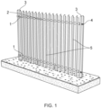
- Figure 1 discloses a traditional palisade fence with support posts 3, rails 1, which extend between the posts 3, and pales 5 for mounting between the rails.
- the pales 5 connect to the rails 1 and are secured using the fixing bolts 2.
- Fish plates 4 are used to join and secure the rails 2 for the adjoining bay of fencing.
- Figure 1 is an example of known prior art fencing.
- the present invention provides a bracket 100 that improves the connection of the pales 300 to the rails 200 to enhance security.
- the Figures 2 to 9 show two embodiments of the bracket 100, one having a W-shaped set of apertures 13,31 for a pale 300 with a W-shaped cross section ( Figures 2 , 7A to 7H and 8A to 8E ) and one bracket having a D-shaped set of apertures 13, 31 that receive a pale 300 with a D-shaped cross section ( Figure 3 , 9A to 9E ).
- Like parts of the brackets have like references.
- the bracket 100 has an L-shaped body 10 with a first returned end 20 for engaging with a rail 200 and a second returned end 30 that is adapted to engage with the rail 200 and to receive a pale 300.
- the second returned end 30 has a first aperture 31, and the body 10 has a second aperture 13 and both the first 31 and second 13 apertures are in the same plane to receive a pale 300 through both apertures 31, 13 so that the pale is located against the rail 200.
- the body 10 is L-shaped and has a first leg 11 longer than a second leg 12.
- the legs 11, 12 are arranged at 90 degrees to each other. It is appreciated that the leg lengths may be altered to correspond to the rail being used.
- first leg 11 At a distal end of the first leg 11 is the first returned end 20 that engages with part of the rail 200. At a distal end of the second leg 12 of the body 10 there is the second returned end 30.
- the first returned end 20 has two faces 21, 22, that together with the first leg 11 of the body define a channel that receives part of the rail 200.
- the two faces 21, 22 of the first returned end 20 are at 90 degrees to each other, and the second face 22 is at 90 degrees with respect to the first leg 11. Therefore the channel is a three sided angular channel.
- the second returned end 30 also has two faces 32, 33 that together with the shorter second leg 12 of the body 10 form a channel.
- the first face 32 and part of the second face 33 engages with part of the rail 200 to locate the bracket 100.
- the two faces 32, 33 of the second returned end 30 are at 90 degrees to each other, and the second face 33 is at 90 degrees with respect to the second leg 12. Therefore the channel is a three sided angular channel.
- Part of the second face 33 and part of the second leg 12, along with the front face of the rail 200 define a three sided channel through which the pale 300 is inserted in use.
- Figures 5 and 6 show front and rear faces of palisade fencing with the brackets 100.
- the brackets 100 have not been secured with a nut and bolt, therefore the front and rear holes 14, 34 are still visible.
- the brackets 100 are only provided on one of the lower rails. It is appreciated that the brackets 100 may be provided on two or more rails 200 for enhanced security. In this way one pale may be secured to multiple rails by multiple brackets.
- Figures 7A to 7H show the steps of fitting the bracket to an L-shaped rail 200.
- the bracket 100 is first placed adjacent to the rail 200 with the first and second legs 11, 12 of the body 10 engaging with the rail 200 ( Figure 7A ).
- the bracket 100 is then rotated about the rail 200 so that the second shorter leg 12 is against a front facing surface 230 of the rail 200 ( Figures 7B, 7C, 7D ).
- the bracket 100 is pulled forward so that the first returned end 20 of the first longer leg 11 engages with an upper edge 210 of the rail 200, and the second returned end 30 of the second shorter leg 12 engages with a lower edge 220 of the rail 200. In this way both returned ends 20, 30 are in contact with the rail 200 and a channel is defined between the bracket and a front face 230 of the rail 200 (see Figure 7D ).
- the channel receives the pale 300 through the apertures 13, 31 (see Figures 7E, 7F and 7G ).
- the pale has a W-shaped cross section to be received though W-shaped apertures 13, 31.
- Brackets 100 are added along one of the bottom rails 200 (see Figure 7H ).
- Figures 2 , 8A to 8E show an embodiment of the bracket 100 with W-shaped apertures 13, 31 for receiving palisade pales with a W-shaped cross section (see Figure 4 ).
- Figures 8A, 8B , 8D and 8E include some preferred dimensions of the bracket 100 that enable the bracket to be used on traditional palisade fencing, although it is appreciated that the bracket may be made in various dimensions to accommodate the fencing components used.
- Figures 3 , 9A to 9E show an embodiment 100 of the bracket with D- shaped apertures 13, 31 for receiving palisade pales 300 with a D-shaped cross section (see Figure 4 ).
- Figures 9A, 9B , 9D and 9E include some preferred dimensions of the bracket 100 that enable use with traditional palisade fencing, although it is appreciated that the bracket may be made in various dimensions to accommodate the fencing components used.
- the bracket is formed from a strong, durable metal such as steel with a thickness of at least 1 mm and preferably at least 2mm.
Landscapes
- Engineering & Computer Science (AREA)
- Architecture (AREA)
- Civil Engineering (AREA)
- Structural Engineering (AREA)
- Fencing (AREA)
Abstract
Description
- The present invention relates to bracket for fencing, in particular a bracket for use with palisade fencing to secure pales.
- A typical palisade fence includes support posts, rails which extend between the posts, and pales for mounting between the rails. The pales connect to the rails and are usually secured using the fixing bolts. A problem associated with palisade fencing is that the pales are most often attached to the face of the rails using fixing means such as bolts, security nuts or rivets that can be removed or damaged in enable access by freeing at least part of a pale from the rail.
- Previous attempts have been made to reduce the opportunity to remove the pales by inserting them through a slotted rail. However, the main drawback with this solution is that the pales have to be inserted from the top rail as the majority of the pales have spearhead spikes or similar, and this means that installation must be completed from height as such fences are designed to be tall, which thereby increases significant health and safety risks and requirements to be met during the installation.
- Also, whilst the slots in the rails may prevent the pales from being shifted to one side, the height of the pales can be adjusted by movement through the slots (i.e. they drop when the fixings are broken) and this allow easier access to climb over or under the fence. Another challenge is that the slotted rail solution is difficult to install on climbing gradients as the pales in the slotted holes restrict any movement.
- The present invention overcomes these problems and provides enhanced security for palisade fencing.
-
GB2465084 (Griffith et.al. - According to a first aspect of the present invention there is provided a bracket for fencing comprising: an L-shaped body, a first returned end for engaging with a rail and a second returned end for engaging with the rail and receiving a pale; characterised in that the second returned end has a first aperture, and the body has a second aperture and both the first and second apertures are in the same plane to receive a pale through both apertures.
- In this way when the bracket is installed, access to the bolt and nut from the front facing side of the fence is prevented. This provides additional security to the overall fence by restricting access to the fixing, thereby preventing unauthorised access.
- Furthermore in the event that any of the pales are compromised, for example where a top becomes bent after access is attempted, the bracket prevents the pales from being shifted to one side to open a gap and allow access through the fence.
- Advantageously the brackets can be installed on any rail, for example on a bottom rail and on a top rail for an enhanced fencing solution.
- The body is L-shaped, providing an opening between the two legs of the body and the retuned ends through which the bracket can be received on the rail. It is appreciated that the bracket may be arranged in a certain orientation in order to be fitted to the rail without requiring the bracket to be forced open in any way.
- Both ends of the L-shaped body have returned ends, so that the returned ends deviate from the alignment of the legs of the body. Preferably the returned ends are angled to define a channel in which part of the rail engages, or part of the rail engages, and a pale is received. The shaping of the returned ends corresponds to the rail so that the bracket fits close to the rail and cannot be easily removed or damaged.
- The first returned end is for engaging with a rail and the second returned end is adapted engage with the rail and to receive a pale. In this way the bracket contacts two regions of the rail to locate the bracket in an orientation in which the pale can be received.
- Preferably the first returned end is shaped and dimensioned to correspond to the profile of at least part of the rail so that the rail is received and held tightly within the first returned end so that it cannot be dislodged by a tool being forced into a gap to lever the bracket from the rail.
- In use the second returned end is shaped to define a channel that provides a region for receiving the pale and has a lip that engages with the rail. As the lip is engaged against the rail the channel is thereby spaced apart from the rail to provide a region which includes the aligned apertures through which the pale passes.
- The second returned end has a first aperture, and one leg of the body has a second aperture and both the first and second apertures are in the same plane to receive a pale through both apertures.
- Preferably the first aperture has a profile that substantially corresponds to the cross-sectional profile of the pale so that the pale is held securely in place.
- Preferably the second aperture also has a profile that substantially corresponds to the cross-sectional profile of the pale. In this way the pale has two regions where the pale is separately secured by the bracket.
- It is appreciated that in some embodiments only the first or second aperture may be shaped to have a profile that corresponds to the cross section of the pale.
- In another embodiment a section of the aperture profile that is outward facing in use is profiled to correspond to the outward facing profile of the pale and the inward facing section of the aperture is straight. In this way the pale is held securely in place and cannot be moved even though only the outward facing section is profiled.
- In a preferred embodiment the first returned end is shaped to provide two faces that together with the body define a channel in which the rail is received. In this way there are three faces that receive part of the rail so that the returned end hooks over part of the rail.
- In some embodiments the faces may be shaped to correspond to the rail, for example inner faces of the returned end may be curved or angled to match the shape of the rail.
- Preferably the second returned end is shaped to provide two faces that together with the body define a channel through which a pale passes. At least one face and part of the second face of the second returned end engage with the rail to locate the bracket and to space the channel that is created away from the rail. In this way part of the second face engages with the rail and part of the second face is part of the channel that receives the pale. The part of the second face that is part of the channel includes the second aperture for the pale.
- In preferred embodiments the body and an opposed face of the second returned end each include holes that are aligned to receive a securing means such as a nut and bolt, typically an anti-vandalisation nut and bolt that receives a nut on the rear face of the fence. The securing means fix the bracket in place and as the fixing is on a rear face it is protected from tampering by an unauthorised person trying to gain access.
- In some embodiments a distal section of the second returned end tapers to a point. This reduces the weight of the bracket and may also help with positioning the bracket on the rail as only a small area of engagement is required.
- Preferred embodiments of the invention will now be described, by way of example and with reference to the Figures in which:
-
-
Figure 1 shows an example of traditional palisade fencing (prior art); -
Figure 2 shows a first embodiment of a bracket for a W-section pale; -
Figure 3 shows a second embodiment of a bracket for a D-section pale; -
Figure 4 shows different shapes of pales; -
Figure 5 shows palisade fencing including the brackets of the present invention; -
Figure 6 shows a rear face of the palisade fencing with brackets; -
Figures 7A to 7H demonstrate the steps of positioning the bracket and installing the pales; -
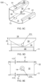
Figure 8A shows a top view of the first embodiment of the bracket; -
Figure 8B shows a side view of the first embodiment of the bracket; -
Figure 8C shows an isometric view of the first embodiment of the bracket; -
Figure 8D shows a rear view of the first embodiment of the bracket; -
Figure 8E shows a front view of the first embodiment of the bracket; -
Figure 9A shows a top view of the second embodiment of the bracket; -
Figure 9B shows a side view of the second embodiment of the bracket; -
Figure 9C shows an isometric view of the second embodiment of the bracket; -
Figure 9D shows a rear view of the second embodiment of the bracket; -
Figure 9E shows a front view of the second embodiment of the bracket; -
Figure 1 discloses a traditional palisade fence withsupport posts 3, rails 1, which extend between theposts 3, and pales 5 for mounting between the rails. The pales 5 connect to therails 1 and are secured using the fixingbolts 2. There are typically 17 pales 5 per each bay of palisade.Fish plates 4 are used to join and secure therails 2 for the adjoining bay of fencing.Figure 1 is an example of known prior art fencing. - The present invention provides a
bracket 100 that improves the connection of the pales 300 to therails 200 to enhance security. TheFigures 2 to 9 show two embodiments of thebracket 100, one having a W-shaped set ofapertures Figures 2 ,7A to 7H and8A to 8E ) and one bracket having a D-shaped set ofapertures Figure 3 ,9A to 9E ). Like parts of the brackets have like references. - The
bracket 100 has an L-shaped body 10 with a first returnedend 20 for engaging with arail 200 and a second returnedend 30 that is adapted to engage with therail 200 and to receive a pale 300. - The second returned
end 30 has afirst aperture 31, and the body 10 has asecond aperture 13 and both the first 31 and second 13 apertures are in the same plane to receive a pale 300 through bothapertures rail 200. - The body 10 is L-shaped and has a
first leg 11 longer than asecond leg 12. Thelegs - At a distal end of the
first leg 11 is the first returnedend 20 that engages with part of therail 200. At a distal end of thesecond leg 12 of the body 10 there is the second returnedend 30. - The first returned
end 20 has twofaces first leg 11 of the body define a channel that receives part of therail 200. The two faces 21, 22 of the first returnedend 20 are at 90 degrees to each other, and thesecond face 22 is at 90 degrees with respect to thefirst leg 11. Therefore the channel is a three sided angular channel. - The second returned
end 30 also has twofaces second leg 12 of the body 10 form a channel. Thefirst face 32 and part of thesecond face 33 engages with part of therail 200 to locate thebracket 100. - The two faces 32, 33 of the second returned
end 30 are at 90 degrees to each other, and thesecond face 33 is at 90 degrees with respect to thesecond leg 12. Therefore the channel is a three sided angular channel. - Part of the
second face 33 and part of thesecond leg 12, along with the front face of therail 200 define a three sided channel through which the pale 300 is inserted in use. -
Figures 5 and 6 show front and rear faces of palisade fencing with thebrackets 100. Thebrackets 100 have not been secured with a nut and bolt, therefore the front andrear holes brackets 100 are only provided on one of the lower rails. It is appreciated that thebrackets 100 may be provided on two ormore rails 200 for enhanced security. In this way one pale may be secured to multiple rails by multiple brackets. -
Figures 7A to 7H show the steps of fitting the bracket to an L-shapedrail 200. Thebracket 100 is first placed adjacent to therail 200 with the first andsecond legs Figure 7A ). Thebracket 100 is then rotated about therail 200 so that the secondshorter leg 12 is against afront facing surface 230 of the rail 200 (Figures 7B, 7C, 7D ). - The
bracket 100 is pulled forward so that the first returnedend 20 of the firstlonger leg 11 engages with anupper edge 210 of therail 200, and the second returnedend 30 of the secondshorter leg 12 engages with alower edge 220 of therail 200. In this way both returned ends 20, 30 are in contact with therail 200 and a channel is defined between the bracket and afront face 230 of the rail 200 (seeFigure 7D ). - The channel receives the pale 300 through the
apertures 13, 31 (seeFigures 7E, 7F and 7G ). In the pictured embodiment the pale has a W-shaped cross section to be received though W-shapedapertures Brackets 100 are added along one of the bottom rails 200 (seeFigure 7H ). In the pictured example, there are threerails 200, and brackets are only used on one of the lower rails to prevent the lower ends of the pales 300 being levered away from thelower rail 200 to gain access. -
Figures 2 ,8A to 8E show an embodiment of thebracket 100 with W-shapedapertures Figure 4 ). -
Figures 8A, 8B ,8D and 8E include some preferred dimensions of thebracket 100 that enable the bracket to be used on traditional palisade fencing, although it is appreciated that the bracket may be made in various dimensions to accommodate the fencing components used. -
Figures 3 ,9A to 9E show anembodiment 100 of the bracket with D- shapedapertures Figure 4 ). -
Figures 9A, 9B ,9D and 9E include some preferred dimensions of thebracket 100 that enable use with traditional palisade fencing, although it is appreciated that the bracket may be made in various dimensions to accommodate the fencing components used. - Preferably the bracket is formed from a strong, durable metal such as steel with a thickness of at least 1 mm and preferably at least 2mm.
- The invention has been described by way of examples only and it will be appreciated that variation may be made to the above-mentioned embodiments without departing from the scope of invention as defined by the claims.
Claims (13)
- A bracket (100) for fencing comprising: an L-shaped body (10), a first returned end (20) for engaging with a rail and a second returned end (30) for engaging with the rail and receiving a pale; characterised in that the second returned end (30) has a first aperture (31), and the body (10) has a second aperture (13) and both the first (31) and second (13) apertures are in the same plane to receive a pale through both apertures.
- A bracket (100) according to claim 1 wherein the first aperture (31) has a first profile.
- A bracket (100) according to claim 2 wherein the second aperture (13) has the first profile.
- A bracket (100) according to claim 2 wherein the second aperture (13) has a second profile that is different to the first profile.
- A bracket (100) according to any preceding claim wherein the first aperture (31) is D-shaped.
- A bracket (100) according to any of claims 1 to 4 wherein the first aperture (31) is W-shaped.
- A bracket (100) according to any preceding claim wherein the second aperture (13) is D-shaped.
- A bracket (100) according to any of claims 1 to 6 wherein the second aperture (13) is W-shaped.
- A bracket (100) according to any preceding claim wherein the legs (11,12) of the body (10) are of different lengths.
- A bracket (100) according to any preceding claim wherein the first returned end (20) is shaped to provide two faces (21,22) that together with the body (10) define a channel suitable for receiving the rail.
- A bracket (100) according to any preceding claim wherein the second returned end (30) is shaped to provide two faces (31, 32) that together with the body (10) define a channel suitable for receiving the rail.
- A bracket (100) according to claim 11 wherein the body (10) and an opposed face (32) of the second returned end (30) each include holes (14, 34) that are aligned to receive a securing means.
- A bracket (100) according to any preceding claim wherein a distal section of the second returned end (12) tapers to a point.
Applications Claiming Priority (1)
| Application Number | Priority Date | Filing Date | Title |
|---|---|---|---|
| GB2219014.4A GB2625524B (en) | 2022-12-16 | 2022-12-16 | A bracket for fencing |
Publications (1)
| Publication Number | Publication Date |
|---|---|
| EP4386157A1 true EP4386157A1 (en) | 2024-06-19 |
Family
ID=85035650
Family Applications (1)
| Application Number | Title | Priority Date | Filing Date |
|---|---|---|---|
| EP23217135.5A Pending EP4386157A1 (en) | 2022-12-16 | 2023-12-15 | A bracket for fencing |
Country Status (2)
| Country | Link |
|---|---|
| EP (1) | EP4386157A1 (en) |
| GB (1) | GB2625524B (en) |
Citations (5)
| Publication number | Priority date | Publication date | Assignee | Title |
|---|---|---|---|---|
| US4078754A (en) * | 1976-12-30 | 1978-03-14 | Gould George T | Fence post sign holder |
| US6874767B1 (en) * | 2002-04-05 | 2005-04-05 | Fence | |
| USD609551S1 (en) * | 2009-10-15 | 2010-02-09 | Gibbs Edward L | Latch assembly |
| GB2465084A (en) | 2008-11-10 | 2010-05-12 | Neal Griffith | Fence kit and method of erecting a fence |
| US20140021425A1 (en) * | 2012-07-23 | 2014-01-23 | Anton Van Es | Fence rail and picket assembly |
-
2022
- 2022-12-16 GB GB2219014.4A patent/GB2625524B/en active Active
-
2023
- 2023-12-15 EP EP23217135.5A patent/EP4386157A1/en active Pending
Patent Citations (5)
| Publication number | Priority date | Publication date | Assignee | Title |
|---|---|---|---|---|
| US4078754A (en) * | 1976-12-30 | 1978-03-14 | Gould George T | Fence post sign holder |
| US6874767B1 (en) * | 2002-04-05 | 2005-04-05 | Fence | |
| GB2465084A (en) | 2008-11-10 | 2010-05-12 | Neal Griffith | Fence kit and method of erecting a fence |
| USD609551S1 (en) * | 2009-10-15 | 2010-02-09 | Gibbs Edward L | Latch assembly |
| US20140021425A1 (en) * | 2012-07-23 | 2014-01-23 | Anton Van Es | Fence rail and picket assembly |
Also Published As
| Publication number | Publication date |
|---|---|
| GB2625524B (en) | 2025-03-05 |
| GB202219014D0 (en) | 2023-02-01 |
| GB2625524A (en) | 2024-06-26 |
| GB2625524A8 (en) | 2025-01-15 |
Similar Documents
| Publication | Publication Date | Title |
|---|---|---|
| AU2010207632B2 (en) | Fencing assembly | |
| US11199278B2 (en) | Cable management assembly | |
| US6969051B1 (en) | Two-part rail with internal picket connection | |
| EP1366254B1 (en) | Security fences | |
| US20070170410A1 (en) | System, method and Apparatus for Assembling a Picket Fence | |
| EP2126254B1 (en) | Self-raking fence panel and method of assembly | |
| US20230123821A1 (en) | Fence | |
| US6863265B2 (en) | Tamper resistant fence | |
| WO2010094081A1 (en) | Fencing system and method of assembly involving concealing of the fasteners between the horizontal rail and vertical pales | |
| AU2002234780A1 (en) | Adjustable fence panel and method of assembly | |
| WO2002072982A1 (en) | Adjustable fence panel and method of assembly | |
| AU2020264029B2 (en) | Ladder guard | |
| AU2020332710B2 (en) | Brackets for stair railings | |
| GB2625524A (en) | A bracket for fencing | |
| US12428869B2 (en) | Security fence | |
| EP3904622B1 (en) | Device for fixing a panel to a fence post | |
| EP2313559B1 (en) | A road rail | |
| CA3081842C (en) | System and method for constructing a railing | |
| GB2372759A (en) | Security fence | |
| US11939788B2 (en) | Fence panel having tabs and method of installation thereof | |
| EP3708742B1 (en) | Fixed guard with improved assembly means | |
| GB2559352A (en) | Security fencing | |
| PL241634B1 (en) | The push-in connector and the method of assembling the push-in connector | |
| US20090321698A1 (en) | Panel Fence System and Method | |
| ZA200904131B (en) | An anti-theft device |
Legal Events
| Date | Code | Title | Description |
|---|---|---|---|
| PUAI | Public reference made under article 153(3) epc to a published international application that has entered the european phase |
Free format text: ORIGINAL CODE: 0009012 |
|
| STAA | Information on the status of an ep patent application or granted ep patent |
Free format text: STATUS: THE APPLICATION HAS BEEN PUBLISHED |
|
| AK | Designated contracting states |
Kind code of ref document: A1 Designated state(s): AL AT BE BG CH CY CZ DE DK EE ES FI FR GB GR HR HU IE IS IT LI LT LU LV MC ME MK MT NL NO PL PT RO RS SE SI SK SM TR |
|
| STAA | Information on the status of an ep patent application or granted ep patent |
Free format text: STATUS: REQUEST FOR EXAMINATION WAS MADE |
|
| 17P | Request for examination filed |
Effective date: 20241202 |
|
| RBV | Designated contracting states (corrected) |
Designated state(s): AL AT BE BG CH CY CZ DE DK EE ES FI FR GB GR HR HU IE IS IT LI LT LU LV MC ME MK MT NL NO PL PT RO RS SE SI SK SM TR |