EP4385940B1 - Abgabesystem für viskose lebensmittel - Google Patents
Abgabesystem für viskose lebensmittel Download PDFInfo
- Publication number
- EP4385940B1 EP4385940B1 EP24173908.5A EP24173908A EP4385940B1 EP 4385940 B1 EP4385940 B1 EP 4385940B1 EP 24173908 A EP24173908 A EP 24173908A EP 4385940 B1 EP4385940 B1 EP 4385940B1
- Authority
- EP
- European Patent Office
- Prior art keywords
- container
- friction
- roller
- viscous food
- outlet
- Prior art date
- Legal status (The legal status is an assumption and is not a legal conclusion. Google has not performed a legal analysis and makes no representation as to the accuracy of the status listed.)
- Active
Links
Images




Classifications
-
- A—HUMAN NECESSITIES
- A23—FOODS OR FOODSTUFFS; TREATMENT THEREOF, NOT COVERED BY OTHER CLASSES
- A23P—SHAPING OR WORKING OF FOODSTUFFS, NOT FULLY COVERED BY A SINGLE OTHER SUBCLASS
- A23P20/00—Coating of foodstuffs; Coatings therefor; Making laminated, multi-layered, stuffed or hollow foodstuffs
- A23P20/10—Coating with edible coatings, e.g. with oils or fats
- A23P20/15—Apparatus or processes for coating with liquid or semi-liquid products
-
- A—HUMAN NECESSITIES
- A21—BAKING; EDIBLE DOUGHS
- A21C—MACHINES OR EQUIPMENT FOR MAKING OR PROCESSING DOUGHS; HANDLING BAKED ARTICLES MADE FROM DOUGH
- A21C9/00—Other apparatus for handling dough or dough pieces
- A21C9/04—Apparatus for spreading granular material on, or sweeping or coating the surfaces of, pieces or sheets of dough
-
- A—HUMAN NECESSITIES
- A21—BAKING; EDIBLE DOUGHS
- A21D—TREATMENT OF FLOUR OR DOUGH FOR BAKING, e.g. BY ADDITION OF MATERIALS; BAKING; BAKERY PRODUCTS
- A21D13/00—Finished or partly finished bakery products
- A21D13/40—Products characterised by the type, form or use
- A21D13/41—Pizzas
-
- B—PERFORMING OPERATIONS; TRANSPORTING
- B05—SPRAYING OR ATOMISING IN GENERAL; APPLYING FLUENT MATERIALS TO SURFACES, IN GENERAL
- B05C—APPARATUS FOR APPLYING FLUENT MATERIALS TO SURFACES, IN GENERAL
- B05C5/00—Apparatus in which liquid or other fluent material is projected, poured or allowed to flow on to the surface of the work
- B05C5/02—Apparatus in which liquid or other fluent material is projected, poured or allowed to flow on to the surface of the work the liquid or other fluent material being discharged through an outlet orifice by pressure, e.g. from an outlet device in contact or almost in contact, with the work
-
- B—PERFORMING OPERATIONS; TRANSPORTING
- B65—CONVEYING; PACKING; STORING; HANDLING THIN OR FILAMENTARY MATERIAL
- B65D—CONTAINERS FOR STORAGE OR TRANSPORT OF ARTICLES OR MATERIALS, e.g. BAGS, BARRELS, BOTTLES, BOXES, CANS, CARTONS, CRATES, DRUMS, JARS, TANKS, HOPPERS, FORWARDING CONTAINERS; ACCESSORIES, CLOSURES, OR FITTINGS THEREFOR; PACKAGING ELEMENTS; PACKAGES
- B65D35/00—Pliable tubular containers adapted to be permanently or temporarily deformed to expel contents, e.g. collapsible tubes for toothpaste or other plastic or semi-liquid material; Holders therefor
- B65D35/24—Pliable tubular containers adapted to be permanently or temporarily deformed to expel contents, e.g. collapsible tubes for toothpaste or other plastic or semi-liquid material; Holders therefor with auxiliary devices
- B65D35/28—Pliable tubular containers adapted to be permanently or temporarily deformed to expel contents, e.g. collapsible tubes for toothpaste or other plastic or semi-liquid material; Holders therefor with auxiliary devices for expelling contents
Definitions
- US 2006/254675 A1 discloses a viscous food dispensing system comprising: a frame, an inlet tube for a pump device, a connector coupled to the inlet tube, a container containing a viscous food product, the container including an outlet at a bottom of the container configured to couple with the connector and a dispensing device comprising: a roller slideably attached to the frame that applies pressure against the container wherein the roller is initially in contact with a top of the container and slides towards the outlet as the viscous food product is expelled.
- the invention provides a system for dispensing viscous food products from a container.
- the viscous food dispensing system includes a detachable door defining at least one elongated aperture along a vertical axis of the detachable door and attachable to a frame of the viscous food dispensing system by at least one hinge.
- the viscous food dispensing system also includes an inlet tube connected with a pump device.
- the viscous food dispensing system also includes a friction-fit connector coupled to the inlet tube.
- the viscous food dispensing system also includes a dispensing device including a roller slideably attached to the frame that applies pressure against the container and the detachable door where the roller is initially in contact with a top of the container and slides towards the outlet as the food product is expelled and a level indicator coupled with the roller that protrudes through the at least one elongated aperture when the detachable door is closed such that the level indicator is visible from an exterior of the detachable door, when the container is disposed between the dispensing device and the detachable door.
- a dispensing device including a roller slideably attached to the frame that applies pressure against the container and the detachable door where the roller is initially in contact with a top of the container and slides towards the outlet as the food product is expelled and a level indicator coupled with the roller that protrudes through the at least one elongated aperture when the detachable door is closed such that the level indicator is visible from an exterior of the detachable door, when the container is disposed between the dispensing
- the cassette for supplying a viscous food product.
- the cassette is reusable and attachable with a pump device.
- the cassette includes a container detachably connected with the cassette, the container containing a viscous food product, the container including an outlet which is at a bottom of the container configured to couple with the pump device via a friction-fit connector.
- the cassette also includes a dispensing device including a roller slideably attached to the cassette at each end of the roller and slideably coupled to an exterior of the container to apply pressure against the container against a door of the cassette, wherein as the dispensing device is initially coupled to a top of the container and slides towards the outlet as the food product is expelled.
- the cassette additionally includes a level indicator coupled with the roller that protrudes through at least one aperture of the cassette when a door of the cassette is closed to provide a level indication of the food product within the container.
- One general aspect, not part of the invention, includes a method of dispensing a viscous food.
- the method includes raising a roller of a food dispensing system to an upper position of a frame.
- the method also includes installing a container containing a viscous food product.
- the method also includes inserting a friction-fit connector of an inlet tube of a pump device of the food dispensing system into an outlet of the container.
- the method also includes closing a door connected with the frame to position the container between the roller and the door to apply pressure on the container and dispense the food product through the inlet tube.
- Embodiments and techniques described herein are directed to systems and methods for dispensing viscous food products, such as pizza sauce, from a container using a dispensing device equipped with a cassette for holding and applying force against the container to remove the food product from the container.
- Viscous food products are food products that have a tendency to adhere to an interior surface of a container.
- the apparatus for dispensing viscous food products may, for example, be used to dispense pizza sauce onto a prepared crust of a pizza.
- the embodiments and techniques described herein provide for easy installation of replaceable food product containers, simple operation, and greater removal of food product from the container resulting in less food waste.
- Other such food and viscous fluid dispensers including condiment dispensers and the like may include systems and components as described herein.
- FIG. 1 shows a perspective view of an apparatus 100 for on-demand distribution of a viscous food product, according to at least one embodiment.
- the apparatus 100 includes a base frame 180 constructed in an open tube-frame fashion.
- the apparatus 100 can have a depth of 24 inches, which is a standard kitchen counter top depth.
- the apparatus 100 includes a pump device 104 and a cassette device 102.
- the cassette device 102 supplies concentrated liquid (e.g. viscous) food product in a unique form.
- the cassette device 102 has several advantages as it requires minimal cleaning, can use pre-packaged concentrated liquid food product in a container as shipped from a factory, includes an indicator showing the level of the concentrated liquid food product remaining in the container, and is configured to couple to one or more different apparatuses.
- cassette devices 102 may be used on one apparatus 100.
- one cassette device may be used with more than one, for example two or more, apparatuses at different times.
- the cassette device 102 can be re-loaded using pliable food containers without pouring or transferring the food product.
- the apparatus 100 includes a table top section 184.
- the table top section 184 may be formed from a thermo-vacuum formed plastic, molded plastic, and/or sheet metal sections which are welded or bolted together.
- the table top section 184 also includes a control panel for electronic interaction with the apparatus 100 by a user.
- a turntable is integrated and rotationally attached to the table top section 184.
- a round pan holding a dough-based food product (e.g. pizza crust) is intended to sit on top of the turntable. The turntable rotates the pan for even distribution of a viscous food-product onto the dough-based food product.
- a control box is attached to an internal shelf within the apparatus 100.
- the control box houses control electronics and a fluid interface for connecting to the pump device 104.
- the apparatus 100 also includes a linear arm 185 which distributes viscous food-product out of a nozzle in an even and smooth manner onto the dough-based food product.
- the linear arm 185 is actuated by a linear actuator integrated within the table top section 184
- the linear arm 185 may be stationary in some examples and connected with the table top section 184.
- the linear arm 185 is intended to move over and across a radius of the turntable at varying speed, as the outer radius of the turntable will naturally have a higher angular speed than the inner radius at a constant angular speed.
- the linear arm 185 is also fluidly connected to the pump device 104, which supplies viscous food-product to the linear arm 185.
- the pump device 104 includes a pump assembly including an electric stepper motor and lead screw.
- the lead screw actuates a piston, which draws in (by vacuum) the viscous food product into a cylinder from an inlet, as illustrated in FIG. 7 ., the piston also pressurizes the cylinder through a second piston actuation and forces out the viscous food-product through an outlet and to the linear arm 185.
- the pump device 104 may also include a pump board which houses electronics for controlling the pump assembly and interfacing with the control box. In some examples, the pump device 104 may be controlled by electronics within the control box. The pump board is in turn controlled by the control box. In some examples, an optional home sensor and limit sensor may be included in the pump device 104 for setting an initial pump position and limiting the travel of the pump, respectively.
- a user of the apparatus 100 will first place a container in the cassette device 102 or check to make sure the cassette device 102 includes the viscous food product.
- the level of the viscous food product included in the cassette device 102 may be determined based on a position of the handles 128 (illustrated in FIG. 3 ) as visible from an exterior of the cassette device 102.
- the user may place a predetermined sized pan (e.g. personal, small, medium, large, extra-large), with a respective sized dough based food-product, onto the turntable.
- the user then interfaces with the control panel to select pan size and desired sauce depth (e.g. dough type).
- the turntable rotates and viscous food-product emerges from the linear arm in an even and consistent manner.
- the linear arm moves along a radius of the turntable, at a varying rate to ensure that the viscous food-product is evenly spread over the surface of the dough based food-product.
- the pump device 104 may dilute concentrated liquid food-product stored in cassette device 102. By using a concentrated liquid food-product, the apparatus 100 needs to be refilled less often. Additionally, the apparatus 100, may adjust the mixing ratio of the dispensed sauce by regulating water intake. For example some pizzas require a thicker sauce while others require a thinner sauce. By using a concentrated liquid food-product, thickness changes may occur on-demand by changing and/or controlling a water valve to control a flow of water into the apparatus 100. Previous apparatuses required changing of the entire sauce supply in order to implement a different sauce thickness.
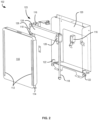
- FIG. 2 shows an exploded view of a cassette device 102 of the apparatus of FIG. 1 , according to at least one embodiment.
- the cassette device 102 is structured in form of a case, with a door 110 connected by a removable hinge including a first component 114 and a second component 122 to a frame 120.
- the first component 114 may protrude from a bottom of the door 110.
- the first component 114 may include a pair of protrusions extending from opposite ends of the bottom of the door 110.
- the second component 122 may be coupled to a bottom of the frame 120 that mates with the bottom of the door 110.
- the second component 122 may include a pair of hooks coupled to opposite ends of the bottom of the frame 120, and configured to receive the pair of protrusions extending from the bottom of the door 110.
- the frame 120 may further include a dispensing device 123.
- the dispensing device 123 includes a roller 124, guide shafts 118, locking devices 116, and sliding blocks 126.
- the roller 124 is connected to sliding blocks 126 which are slidably attached to respective guide shafts 118 extending along the vertical sides of the cassette device 102.
- the dispensing device 123 is configured to enable the roller 124 to freely slide down the guide shafts 118.
- the roller 124 is of significant weight, and preferably weighs 2.72-3.63 kgs (6-8 lbs) such that the roller 124 descends under its own weight due to gravity to dispense (e.g. squeeze out) the viscous food product from a container.
- the roller 124 may be weighted with dense materials and/or the roller 124 may be formed of a combination of materials including a high density plastic, a metal, or other such rigid and dense materials. According to some embodiments, the roller 124 may rotate along a horizontal axis extending between the two opposite sliding blocks 126. Alternatively, the roller 124 may be static with respect to the sliding blocks 126.
- handles 128 or protruding elements may be connected that enable easy movement of the roller 124 by a user, for example to raise the roller 124 to install a new food container in the cassette device 102.
- the handles 128, shown in FIG. 3 may be configured to protrude through the door 110 to provide a visual indication of the height of the roller 124 within the cassette to provide a fast and easy way to evaluate level marker for the user to visualize and know when the food container must be replaced.
- the door 110 includes one or more elongated apertures 112, one per each handle 128, or other protrusions from the sliding blocks 126 to protrude when the door 110 is closed and thereby provide the visual level indication without opening the cassette device 102.
- the door 110 of the cassette device 102 also includes hanging devices 113 for connecting to a removable food container and enabling quick connection and replacement of the food container.
- the hanging devices 113 may include clips, clamps, threaded connections, and other such releasable securements.
- the cassette device 102 also includes a pair of locking devices 116 that sit adjacent each of the guide shafts 118.
- the locking devices 116 serve as retainers configured to release and retain the sliding blocks and therefore interface with the sliding blocks 126 to releasably secure the roller 124 in an upper position closer to the top end 190 of the door 110, for example while replacing the food container.
- the locking devices 116 may include a latch mechanism that is spring-actuated to support the sliding block 126 when in contact.
- the locking devices 116 are actuated to release the roller 124 and the sliding blocks 126 to descend along the guide shafts 118.
- the locking devices 116 may be actuated manually by the user depressing the latch or may be actuated by closing the door 110. As the door 110 is shut, the door depresses the latch of the locking device 116 and releases the sliding block 126.
- Other hardware shown in FIG. 2 is for mounting of various devices to the frame 120 and securing the frame 120 to the apparatus 100.
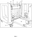
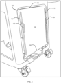
- FIG. 3 shows a portion of the apparatus 100 of FIG. 1 showing the cassette device 102 installed with a door 110 thereof open, according to at least one embodiment.
- FIG. 3 shows the cassette device 102 in use. While FIG. 3 shows the cassette device 102 in an open position for illustrative reasons only, normally the cassette device 102 is used in a closed position.
- FIG. 3 illustrates an inlet 150 for the pump device 104 including a friction-fit connector shown in FIG. 9 .
- a container such as a pliable food container bag
- the hanging devices 113 such as a clip or other securing device at or near a top of the door 110.
- the roller 124 is raised to the top of the guide shafts 118 and retained in position by the locking devices 116.
- the roller 124 may be raised by grasping the handles 128 and lifting (e.g. sliding) the roller 124 to the top of the guide shafts 118.
- the inlet 150 is connected to an outlet of the container, positioned at or near the bottom of the container.
- the inlet 150 may be connected to the outlet of the container using the friction-fit connector 151 described with respect to FIG. 9 .
- FIG. 11 shows the container 152 of FIG. 7 having an interior funnel shape and connected to the friction-fit connector 151 of FIG. 9 , according to at least one embodiment.
- the container 152 is a pliable container having interior seams 156 that form the interior funnel shape to direct the viscous food product towards the outlet 154 as the roller 124 descends.
- FIGS. 8A and 8B show the locking devices 116 for securing the roller 124 during installation of a new container, according to at least one embodiment.
- the locking devices 116 include a latch mechanism that engages with the sliding blocks 126 .
- the locking devices 116 retain the roller 124 in an uppermost position, each of the locking devices 116 retains a corresponding sliding block 126 until released, either by actuating the locking devices 116 manually or by shutting door 110, as described above.
- Door 110 may include tabs or protrusions to depress the latch of locking device 116 and cause the locking devices 116 to disengage from the sliding blocks 126 so the roller 124 may slide down guide shafts 118 under its own weight.
- FIG. 9 shows a friction-fit connector 151 (e.g. friction-fit strainer connector) for connecting an inlet 150 of the pump device 104 of FIG. 7 to the container 152A/B through outlet 154, according to at least one embodiment.
- the friction-fit connector 151 may be referred to as an inlet suction strainer.
- the friction-fit connector 151 may be part of the inlet 150 in some examples, such as with an integrally formed connector that is part of inlet 150.
- the friction-fit connector 151 includes a barbed connection 160 (e.g. a first portion), a stop plate 162, a cylindrical tube 164 (e.g. a second portion), and defines a first opening 168 and a second plurality of openings 166.
- the barbed connection 160 connects the inlet 150 to a tube coupled to the pump device 104.
- the barbed connection may be any other type of tube connection including threaded connections, adhesive connections, friction-fit connections, and the like.
- the stop plate 162 prevents over insertion of the inlet 150 into the outlet 154 of the container 152A/B.
- the stop plate 162 also provides a stop position for the tube to connect to the barbed connection 160.
- the cylindrical tube 164 provides a conduit from the second plurality of openings 166 and the first opening 168 and the tube connected to the barbed connection 160.
- the first opening 168 may be the primary opening and the second plurality of openings 166 may be secondary openings for funneling the food product from the container toward the pump tube.
- the secondary openings increase the open surface area in the cylindrical tube 164 and may increase an amount of food product extracted from container 152A/B.
- the cylindrical tube includes the second plurality of openings 166 in a lateral wall, perpendicular to the axis of the cylindrical tube 164.
- the first opening 168 is at an end of the cylindrical tube 164.
- the first opening 168 may provide a passage for food product to exit the container 152A/B.
- the second plurality of openings 166 may serve to increase a flow rate of food product and/or an amount of food product that may flow through the friction-fit connector 151 by providing a greater open surface area into the inlet 150.
- the second plurality of openings 166 are positioned on the lateral wall such that food product that adheres to the interior sides of the container 152A/B may enter inlet 150 through the second plurality of openings 166 which are positioned adjacent the internal walls of the container 152A/B surrounding outlet 154. As food product is funneled towards outlet 154, the food product near or adhering to the inner walls may travel through the second plurality of openings 166 while food product from a central portion of the container 152A/B may enter through the first opening 168.
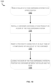
- FIG. 10 shows a flowchart of a method 1000 for dispensing a viscous food product, not part of the present invention.
- the method 1000 may be performed using embodiment and examples described herein, including the apparatus 100, the cassette device 102, and other embodiments and examples described herein.
- the method 1000 includes raising a roller of a food dispensing system to an upper position.
- the roller may be the roller 124 that is raised, along guide shafts 118 of the dispensing device 123 to an upper position where the locking devices 116 retain the sliding blocks 126 and support the weight of the roller 124.
- the method 1000 includes inserting a friction-fit connector of an inlet tube of a pump device of the food dispensing system into an outlet of the container.
- the friction-fit connector may be the friction-fit connector 151 that fits into outlet 154 through a friction-fit as the friction-fit connector 151 stretches the diameter of the outlet 154 due to the friction-fit connector 151 having a larger diameter than an inner diameter of the outlet 154.
- the friction-fit connector 151 is inserted into the container 152A/B such that openings of the friction-fit connector strain the food product into the inlet 150.
Landscapes
- Life Sciences & Earth Sciences (AREA)
- Engineering & Computer Science (AREA)
- Food Science & Technology (AREA)
- Chemical & Material Sciences (AREA)
- Oil, Petroleum & Natural Gas (AREA)
- Polymers & Plastics (AREA)
- Food-Manufacturing Devices (AREA)
- Basic Packing Technique (AREA)
- Confectionery (AREA)
- Feeding, Discharge, Calcimining, Fusing, And Gas-Generation Devices (AREA)
Claims (8)
- Ausgabesystem für viskose Lebensmittel, umfassend:eine abnehmbare Tür (110), die mindestens eine längliche Öffnung (112) entlang einer vertikalen Achse der abnehmbaren Tür (110) definiert und an einem Rahmen (120) des Ausgabesystems für viskose Lebensmittel durch mindestens ein Scharnier anbringbar ist;ein Einlass (150) - Rohr für eine Pumpvorrichtung (104);einen Reibpassungsverbinder (151), der mit dem Einlass (150) - Rohr der Pumpvorrichtung (104) gekoppelt ist;einen Behälter (152A/B), der abnehmbar mit der abnehmbaren Tür (110) verbunden ist, wobei der Behälter (152A/B) ein viskoses Lebensmittelprodukt enthält, wobei der Behälter (152A/B) einen Auslass (154) an einem Boden des Behälters (152A/B) umfasst, der konfiguriert ist, um mit dem Reibpassungsverbinder (151) des Einlass (150) - Rohrs über Reibpassung gekoppelt zu werden; undeine Ausgabevorrichtung (123), umfassend:eine Rolle (124), die verschiebbar an dem Rahmen (120) angebracht ist,die Druck gegen den Behälter (152A/B) und die abnehmbare Tür (110) ausübt, wobei die Rolle (124) anfänglich in Kontakt mit einer Oberseite des Behälters (152A/B) ist und zu dem Auslass (154) gleitet, wenn das viskose Lebensmittelprodukt ausgestoßen wird; undeinen Füllstandsanzeiger, der mit der Rolle (124) gekoppelt ist, der durch die mindestens eine längliche Öffnung (112) vorsteht, wenn die abnehmbare Tür (110) geschlossen ist, sodass der Füllstandsanzeiger von einer Außenseite der abnehmbaren Tür (110) sichtbar ist, wenn der Behälter (152A/B) zwischen der Ausgabevorrichtung (123) und der abnehmbaren Tür (110) angeordnet ist.
- Ausgabesystem für viskose Lebensmittel nach Anspruch 1, ferner umfassend einen Halter, der mit dem Rahmen (120) verbunden ist, der die Rolle (124) an einer Oberseite des Rahmens (120) lösbar hält, wobei der Halter konfiguriert ist, um die Rolle (124) freizugeben, wenn die abnehmbare Tür (110) geschlossen ist.
- Ausgabesystem für viskose Lebensmittel nach Anspruch 1, wobei der Reibpassungsverbinder (151) einen ersten Abschnitt zur Erstreckung in das Einlass (150) - Rohr der Pumpvorrichtung (104) und einen zweiten Abschnitt zur Erstreckung in den Auslass (154) des Behälters (152A/B) umfasst, wobei der zweite Abschnitt eine primäre Öffnung (168) und eine oder mehrere sekundäre Öffnungen (166) umfasst, wobei die primäre Öffnung (168) an einem Ende des Reibpassungsverbinders (151) angeordnet ist und die eine oder mehreren sekundären Öffnungen (166) auf einer Seite des Reibpassungsverbinders (151) angeordnet sind, um es dem viskosen Lebensmittelprodukt zu ermöglichen, den Behälter (152A/B) durch den Reibpassungsverbinder (151) zu verlassen, wobei die eine oder mehreren sekundären Öffnungen (166) eine Menge des viskosen Lebensmittelprodukts erhöhen, das aus dem Behälter (152A/B) entnommen wird.
- Ausgabesystem für viskose Lebensmittel nach Anspruch 1, wobei der Auslass (154) ein elastischer Auslass (154) ist und ein Außendurchmesser des Reibpassungsverbinders (151) größer als ein ungedehnter Innendurchmesser des Auslasses (154) ist.
- Ausgabesystem für viskose Lebensmittel nach Anspruch 1, wobei der Behälter (152A/B) ein formbarer Kunststoffbeutel ist.
- Ausgabesystem für viskose Lebensmittel nach Anspruch 1, wobei der Behälter (152A/B) eine Trichterform von einem oberen Ende des Behälters (152A/B) zu einem unteren Ende des Behälters (152A/B) benachbart zu dem Auslass (154) aufweist.
- Ausgabesystem für viskose Lebensmittel nach Anspruch 1, wobei die Rolle (124) aufgrund der Schwerkraft, die auf die Rolle (124) wirkt, zu dem Auslass (154) gleitet.
- Ausgabesystem für viskose Lebensmittel nach Anspruch 1, wobei während des Betriebs ein Niederdruckbereich an dem Einlass (150) - Rohr den Reibpassungsverbinder (151) weiter in das Einlass (150) - Rohr zieht, um die Verbindung zwischen dem Einlass (150) - Rohr und dem Reibpassungsverbinder (151) zu verstärken.
Priority Applications (1)
| Application Number | Priority Date | Filing Date | Title |
|---|---|---|---|
| EP24219504.8A EP4497329B1 (de) | 2020-12-04 | 2021-12-03 | Kassette zur zufuhr eines viskosen lebensmittelprodukts |
Applications Claiming Priority (3)
| Application Number | Priority Date | Filing Date | Title |
|---|---|---|---|
| US17/112,943 US11576418B2 (en) | 2020-12-04 | 2020-12-04 | Viscous food dispensing system |
| PCT/US2021/072744 WO2022120387A1 (en) | 2020-12-04 | 2021-12-03 | Viscous food dispensing system |
| EP21901667.2A EP4251557A1 (de) | 2020-12-04 | 2021-12-03 | Abgabesystem für viskose lebensmittel |
Related Parent Applications (1)
| Application Number | Title | Priority Date | Filing Date |
|---|---|---|---|
| EP21901667.2A Division EP4251557A1 (de) | 2020-12-04 | 2021-12-03 | Abgabesystem für viskose lebensmittel |
Related Child Applications (2)
| Application Number | Title | Priority Date | Filing Date |
|---|---|---|---|
| EP24219504.8A Division EP4497329B1 (de) | 2020-12-04 | 2021-12-03 | Kassette zur zufuhr eines viskosen lebensmittelprodukts |
| EP24219504.8A Division-Into EP4497329B1 (de) | 2020-12-04 | 2021-12-03 | Kassette zur zufuhr eines viskosen lebensmittelprodukts |
Publications (3)
| Publication Number | Publication Date |
|---|---|
| EP4385940A2 EP4385940A2 (de) | 2024-06-19 |
| EP4385940A3 EP4385940A3 (de) | 2024-08-28 |
| EP4385940B1 true EP4385940B1 (de) | 2025-06-25 |
Family
ID=81849414
Family Applications (3)
| Application Number | Title | Priority Date | Filing Date |
|---|---|---|---|
| EP24219504.8A Active EP4497329B1 (de) | 2020-12-04 | 2021-12-03 | Kassette zur zufuhr eines viskosen lebensmittelprodukts |
| EP24173908.5A Active EP4385940B1 (de) | 2020-12-04 | 2021-12-03 | Abgabesystem für viskose lebensmittel |
| EP21901667.2A Withdrawn EP4251557A1 (de) | 2020-12-04 | 2021-12-03 | Abgabesystem für viskose lebensmittel |
Family Applications Before (1)
| Application Number | Title | Priority Date | Filing Date |
|---|---|---|---|
| EP24219504.8A Active EP4497329B1 (de) | 2020-12-04 | 2021-12-03 | Kassette zur zufuhr eines viskosen lebensmittelprodukts |
Family Applications After (1)
| Application Number | Title | Priority Date | Filing Date |
|---|---|---|---|
| EP21901667.2A Withdrawn EP4251557A1 (de) | 2020-12-04 | 2021-12-03 | Abgabesystem für viskose lebensmittel |
Country Status (7)
| Country | Link |
|---|---|
| US (1) | US11576418B2 (de) |
| EP (3) | EP4497329B1 (de) |
| CN (1) | CN116583391B (de) |
| AU (1) | AU2021392053B2 (de) |
| CA (1) | CA3200396A1 (de) |
| MX (2) | MX2023006452A (de) |
| WO (1) | WO2022120387A1 (de) |
Family Cites Families (17)
| Publication number | Priority date | Publication date | Assignee | Title |
|---|---|---|---|---|
| US3198389A (en) | 1963-12-18 | 1965-08-03 | Thomas B Dunning | Tooth paste dispensing cabinet |
| US4639251A (en) * | 1985-06-28 | 1987-01-27 | Kabivitrum, Inc. | Flexible collapsible container with liquid level indicating device |
| US6196420B1 (en) * | 1999-09-09 | 2001-03-06 | Nestec S.A. | Pumpless dispenser for viscous food products |
| US6892901B2 (en) | 2002-02-08 | 2005-05-17 | Automatic Bar Controls, Inc. | Sauce pumping apparatus |
| US7074277B2 (en) | 2002-02-08 | 2006-07-11 | Automatic Bar Controls, Inc. | Rotary sauce dispensing apparatus |
| US6892629B2 (en) | 2002-02-08 | 2005-05-17 | Automatic Bar Controls, Inc. | System for pumping and dispensing sauce |
| AU2003222654B2 (en) * | 2002-04-22 | 2010-06-10 | Restaurant Technology, Inc. | Automated food processing system and method |
| FR2851241B1 (fr) * | 2003-02-13 | 2005-11-11 | Rhodia Chimie Sa | Procede de vidange d'un conteneur souple renfermant un produit visqueux |
| US7086428B2 (en) * | 2003-05-01 | 2006-08-08 | Lancer Partnership, Ltd. | Evacuation system |
| US7448418B1 (en) * | 2004-04-02 | 2008-11-11 | Automatic Bar Controls, Inc. | Food product bag-to-pump connector |
| JP2006220081A (ja) * | 2005-02-10 | 2006-08-24 | Hitachi Ltd | 燃料供給装置 |
| US7581661B2 (en) | 2006-05-04 | 2009-09-01 | Thomas Joshua J | Multipurpose tooth paste dispenser |
| US20080135426A1 (en) | 2006-11-29 | 2008-06-12 | Automatic Bar Controls, Inc. | Dispensing Apparatus Component System |
| US7993049B2 (en) | 2008-10-16 | 2011-08-09 | Automatic Bar Controls, Inc. | Turntable for on-demand mixing and distributing of a food product |
| US8342367B2 (en) | 2008-10-16 | 2013-01-01 | Automatic Bar Controls, Inc. | Cassette and vat supply source for an on-demand mixing and distributing of a food product |
| US9505600B2 (en) * | 2013-11-13 | 2016-11-29 | TRV Dispense, LLC | Soft food and beverage dispenser |
| CN111417584B (zh) * | 2017-11-23 | 2022-10-25 | 雀巢产品有限公司 | 用于食物或饮料容器的柔性装配组件 |
-
2020
- 2020-12-04 US US17/112,943 patent/US11576418B2/en active Active
-
2021
- 2021-12-03 MX MX2023006452A patent/MX2023006452A/es unknown
- 2021-12-03 CN CN202180081813.6A patent/CN116583391B/zh active Active
- 2021-12-03 EP EP24219504.8A patent/EP4497329B1/de active Active
- 2021-12-03 WO PCT/US2021/072744 patent/WO2022120387A1/en not_active Ceased
- 2021-12-03 EP EP24173908.5A patent/EP4385940B1/de active Active
- 2021-12-03 EP EP21901667.2A patent/EP4251557A1/de not_active Withdrawn
- 2021-12-03 AU AU2021392053A patent/AU2021392053B2/en active Active
- 2021-12-03 CA CA3200396A patent/CA3200396A1/en active Pending
-
2023
- 2023-05-31 MX MX2026001838A patent/MX2026001838A/es unknown
Also Published As
| Publication number | Publication date |
|---|---|
| EP4497329A2 (de) | 2025-01-29 |
| US11576418B2 (en) | 2023-02-14 |
| CN116583391B (zh) | 2024-10-29 |
| EP4385940A3 (de) | 2024-08-28 |
| WO2022120387A1 (en) | 2022-06-09 |
| EP4497329A3 (de) | 2025-02-26 |
| MX2023006452A (es) | 2023-08-09 |
| MX2026001838A (es) | 2026-04-01 |
| EP4385940A2 (de) | 2024-06-19 |
| EP4497329B1 (de) | 2026-03-25 |
| EP4251557A1 (de) | 2023-10-04 |
| AU2021392053A9 (en) | 2024-05-23 |
| CN116583391A (zh) | 2023-08-11 |
| US20220175012A1 (en) | 2022-06-09 |
| AU2021392053B2 (en) | 2025-12-18 |
| AU2021392053A1 (en) | 2023-07-13 |
| CA3200396A1 (en) | 2022-06-09 |
Similar Documents
| Publication | Publication Date | Title |
|---|---|---|
| EP3068724B1 (de) | Spender für weiche nahrungsmittel und getränke | |
| US20100097881A1 (en) | Apparatus and Method for Mixing and Distributing a Food Product | |
| US6708741B1 (en) | Beverage dispenser | |
| US10034584B2 (en) | Fluid dispenser and fluid refill system for fluid dispenser | |
| US3653556A (en) | Liquid dispensing apparatus | |
| EP1595483A2 (de) | Scharnierendes Spendergehaüse und Adapter | |
| TW200820911A (en) | Chilled topping dispenser | |
| AU2009303519B2 (en) | Apparatus and method and turntable for on-demand distributing of a food product | |
| US8342367B2 (en) | Cassette and vat supply source for an on-demand mixing and distributing of a food product | |
| EP4497329B1 (de) | Kassette zur zufuhr eines viskosen lebensmittelprodukts | |
| US7993049B2 (en) | Turntable for on-demand mixing and distributing of a food product | |
| HK40107002A (en) | Viscous food dispensing system | |
| HK40107002B (en) | Viscous food dispensing system | |
| WO2016144997A1 (en) | Pump style dispense mechanism for flowable product packaging | |
| US20150289704A1 (en) | Dispenser for measured doses of liquid and method of using | |
| US20110033588A1 (en) | System and method for dispensing oil for popping popcorn | |
| CN214397312U (zh) | 丝杆互锁定量出饭装置 | |
| US20100095887A1 (en) | Electronic Systems and Methods for Distributing a Food Product Over a Turntable | |
| EP3435779A1 (de) | Spender | |
| AU2014221281B2 (en) | Apparatus and method and turntable for on-demand distributing of a food product | |
| CA3045434A1 (en) | Soft food and beverage dispenser | |
| US20210129473A1 (en) | Hydraulic Press For Food Items | |
| CA3038833A1 (en) | Soft food and beverage dispenser |
Legal Events
| Date | Code | Title | Description |
|---|---|---|---|
| PUAI | Public reference made under article 153(3) epc to a published international application that has entered the european phase |
Free format text: ORIGINAL CODE: 0009012 |
|
| STAA | Information on the status of an ep patent application or granted ep patent |
Free format text: STATUS: THE APPLICATION HAS BEEN PUBLISHED |
|
| AC | Divisional application: reference to earlier application |
Ref document number: 4251557 Country of ref document: EP Kind code of ref document: P |
|
| AK | Designated contracting states |
Kind code of ref document: A2 Designated state(s): AL AT BE BG CH CY CZ DE DK EE ES FI FR GB GR HR HU IE IS IT LI LT LU LV MC MK MT NL NO PL PT RO RS SE SI SK SM TR |
|
| REG | Reference to a national code |
Ref country code: DE Ref legal event code: R079 Free format text: PREVIOUS MAIN CLASS: B67D0001040000 Ipc: A21C0009040000 Ref document number: 602021033142 Country of ref document: DE |
|
| PUAL | Search report despatched |
Free format text: ORIGINAL CODE: 0009013 |
|
| AK | Designated contracting states |
Kind code of ref document: A3 Designated state(s): AL AT BE BG CH CY CZ DE DK EE ES FI FR GB GR HR HU IE IS IT LI LT LU LV MC MK MT NL NO PL PT RO RS SE SI SK SM TR |
|
| RIC1 | Information provided on ipc code assigned before grant |
Ipc: A21C 9/04 20060101AFI20240719BHEP |
|
| REG | Reference to a national code |
Ref country code: HK Ref legal event code: DE Ref document number: 40107002 Country of ref document: HK |
|
| STAA | Information on the status of an ep patent application or granted ep patent |
Free format text: STATUS: REQUEST FOR EXAMINATION WAS MADE |
|
| GRAP | Despatch of communication of intention to grant a patent |
Free format text: ORIGINAL CODE: EPIDOSNIGR1 |
|
| STAA | Information on the status of an ep patent application or granted ep patent |
Free format text: STATUS: GRANT OF PATENT IS INTENDED |
|
| 17P | Request for examination filed |
Effective date: 20241217 |
|
| INTG | Intention to grant announced |
Effective date: 20250121 |
|
| GRAS | Grant fee paid |
Free format text: ORIGINAL CODE: EPIDOSNIGR3 |
|
| GRAA | (expected) grant |
Free format text: ORIGINAL CODE: 0009210 |
|
| STAA | Information on the status of an ep patent application or granted ep patent |
Free format text: STATUS: THE PATENT HAS BEEN GRANTED |
|
| AC | Divisional application: reference to earlier application |
Ref document number: 4251557 Country of ref document: EP Kind code of ref document: P |
|
| AK | Designated contracting states |
Kind code of ref document: B1 Designated state(s): AL AT BE BG CH CY CZ DE DK EE ES FI FR GB GR HR HU IE IS IT LI LT LU LV MC MK MT NL NO PL PT RO RS SE SI SK SM TR |
|
| REG | Reference to a national code |
Ref country code: GB Ref legal event code: FG4D |
|
| REG | Reference to a national code |
Ref country code: CH Ref legal event code: EP |
|
| REG | Reference to a national code |
Ref country code: CH Ref legal event code: EP |
|
| REG | Reference to a national code |
Ref country code: IE Ref legal event code: FG4D |
|
| REG | Reference to a national code |
Ref country code: DE Ref legal event code: R096 Ref document number: 602021033142 Country of ref document: DE |
|
| PG25 | Lapsed in a contracting state [announced via postgrant information from national office to epo] |
Ref country code: FI Free format text: LAPSE BECAUSE OF FAILURE TO SUBMIT A TRANSLATION OF THE DESCRIPTION OR TO PAY THE FEE WITHIN THE PRESCRIBED TIME-LIMIT Effective date: 20250625 |
|
| REG | Reference to a national code |
Ref country code: LT Ref legal event code: MG9D |
|
| PG25 | Lapsed in a contracting state [announced via postgrant information from national office to epo] |
Ref country code: GR Free format text: LAPSE BECAUSE OF FAILURE TO SUBMIT A TRANSLATION OF THE DESCRIPTION OR TO PAY THE FEE WITHIN THE PRESCRIBED TIME-LIMIT Effective date: 20250926 Ref country code: NO Free format text: LAPSE BECAUSE OF FAILURE TO SUBMIT A TRANSLATION OF THE DESCRIPTION OR TO PAY THE FEE WITHIN THE PRESCRIBED TIME-LIMIT Effective date: 20250925 |
|
| PG25 | Lapsed in a contracting state [announced via postgrant information from national office to epo] |
Ref country code: BG Free format text: LAPSE BECAUSE OF FAILURE TO SUBMIT A TRANSLATION OF THE DESCRIPTION OR TO PAY THE FEE WITHIN THE PRESCRIBED TIME-LIMIT Effective date: 20250625 |
|
| PG25 | Lapsed in a contracting state [announced via postgrant information from national office to epo] |
Ref country code: HR Free format text: LAPSE BECAUSE OF FAILURE TO SUBMIT A TRANSLATION OF THE DESCRIPTION OR TO PAY THE FEE WITHIN THE PRESCRIBED TIME-LIMIT Effective date: 20250625 |
|
| PGFP | Annual fee paid to national office [announced via postgrant information from national office to epo] |
Ref country code: FR Payment date: 20250930 Year of fee payment: 5 |
|
| PG25 | Lapsed in a contracting state [announced via postgrant information from national office to epo] |
Ref country code: RS Free format text: LAPSE BECAUSE OF FAILURE TO SUBMIT A TRANSLATION OF THE DESCRIPTION OR TO PAY THE FEE WITHIN THE PRESCRIBED TIME-LIMIT Effective date: 20250925 |
|
| PG25 | Lapsed in a contracting state [announced via postgrant information from national office to epo] |
Ref country code: LV Free format text: LAPSE BECAUSE OF FAILURE TO SUBMIT A TRANSLATION OF THE DESCRIPTION OR TO PAY THE FEE WITHIN THE PRESCRIBED TIME-LIMIT Effective date: 20250625 |
|
| REG | Reference to a national code |
Ref country code: NL Ref legal event code: MP Effective date: 20250625 |
|
| PG25 | Lapsed in a contracting state [announced via postgrant information from national office to epo] |
Ref country code: NL Free format text: LAPSE BECAUSE OF FAILURE TO SUBMIT A TRANSLATION OF THE DESCRIPTION OR TO PAY THE FEE WITHIN THE PRESCRIBED TIME-LIMIT Effective date: 20250625 |
|
| PG25 | Lapsed in a contracting state [announced via postgrant information from national office to epo] |
Ref country code: PT Free format text: LAPSE BECAUSE OF FAILURE TO SUBMIT A TRANSLATION OF THE DESCRIPTION OR TO PAY THE FEE WITHIN THE PRESCRIBED TIME-LIMIT Effective date: 20251027 |
|
| REG | Reference to a national code |
Ref country code: AT Ref legal event code: MK05 Ref document number: 1805470 Country of ref document: AT Kind code of ref document: T Effective date: 20250625 |
|
| PG25 | Lapsed in a contracting state [announced via postgrant information from national office to epo] |
Ref country code: IS Free format text: LAPSE BECAUSE OF FAILURE TO SUBMIT A TRANSLATION OF THE DESCRIPTION OR TO PAY THE FEE WITHIN THE PRESCRIBED TIME-LIMIT Effective date: 20251025 |
|
| PGFP | Annual fee paid to national office [announced via postgrant information from national office to epo] |
Ref country code: DE Payment date: 20250930 Year of fee payment: 5 |
|
| PGFP | Annual fee paid to national office [announced via postgrant information from national office to epo] |
Ref country code: GB Payment date: 20251001 Year of fee payment: 5 |
|
| PG25 | Lapsed in a contracting state [announced via postgrant information from national office to epo] |
Ref country code: AT Free format text: LAPSE BECAUSE OF FAILURE TO SUBMIT A TRANSLATION OF THE DESCRIPTION OR TO PAY THE FEE WITHIN THE PRESCRIBED TIME-LIMIT Effective date: 20250625 Ref country code: SM Free format text: LAPSE BECAUSE OF FAILURE TO SUBMIT A TRANSLATION OF THE DESCRIPTION OR TO PAY THE FEE WITHIN THE PRESCRIBED TIME-LIMIT Effective date: 20250625 |
|
| PG25 | Lapsed in a contracting state [announced via postgrant information from national office to epo] |
Ref country code: CZ Free format text: LAPSE BECAUSE OF FAILURE TO SUBMIT A TRANSLATION OF THE DESCRIPTION OR TO PAY THE FEE WITHIN THE PRESCRIBED TIME-LIMIT Effective date: 20250625 |
|
| PG25 | Lapsed in a contracting state [announced via postgrant information from national office to epo] |
Ref country code: PL Free format text: LAPSE BECAUSE OF FAILURE TO SUBMIT A TRANSLATION OF THE DESCRIPTION OR TO PAY THE FEE WITHIN THE PRESCRIBED TIME-LIMIT Effective date: 20250625 |
|
| PG25 | Lapsed in a contracting state [announced via postgrant information from national office to epo] |
Ref country code: EE Free format text: LAPSE BECAUSE OF FAILURE TO SUBMIT A TRANSLATION OF THE DESCRIPTION OR TO PAY THE FEE WITHIN THE PRESCRIBED TIME-LIMIT Effective date: 20250625 |
|
| PG25 | Lapsed in a contracting state [announced via postgrant information from national office to epo] |
Ref country code: SK Free format text: LAPSE BECAUSE OF FAILURE TO SUBMIT A TRANSLATION OF THE DESCRIPTION OR TO PAY THE FEE WITHIN THE PRESCRIBED TIME-LIMIT Effective date: 20250625 |
|
| PG25 | Lapsed in a contracting state [announced via postgrant information from national office to epo] |
Ref country code: ES Free format text: LAPSE BECAUSE OF FAILURE TO SUBMIT A TRANSLATION OF THE DESCRIPTION OR TO PAY THE FEE WITHIN THE PRESCRIBED TIME-LIMIT Effective date: 20250625 |
|
| PG25 | Lapsed in a contracting state [announced via postgrant information from national office to epo] |
Ref country code: RO Free format text: LAPSE BECAUSE OF FAILURE TO SUBMIT A TRANSLATION OF THE DESCRIPTION OR TO PAY THE FEE WITHIN THE PRESCRIBED TIME-LIMIT Effective date: 20250625 |
|
| PG25 | Lapsed in a contracting state [announced via postgrant information from national office to epo] |
Ref country code: DK Free format text: LAPSE BECAUSE OF FAILURE TO SUBMIT A TRANSLATION OF THE DESCRIPTION OR TO PAY THE FEE WITHIN THE PRESCRIBED TIME-LIMIT Effective date: 20250625 |
|
| PG25 | Lapsed in a contracting state [announced via postgrant information from national office to epo] |
Ref country code: IT Free format text: LAPSE BECAUSE OF FAILURE TO SUBMIT A TRANSLATION OF THE DESCRIPTION OR TO PAY THE FEE WITHIN THE PRESCRIBED TIME-LIMIT Effective date: 20250625 |
|
| PLBE | No opposition filed within time limit |
Free format text: ORIGINAL CODE: 0009261 |
|
| STAA | Information on the status of an ep patent application or granted ep patent |
Free format text: STATUS: NO OPPOSITION FILED WITHIN TIME LIMIT |
|
| REG | Reference to a national code |
Ref country code: CH Ref legal event code: L10 Free format text: ST27 STATUS EVENT CODE: U-0-0-L10-L00 (AS PROVIDED BY THE NATIONAL OFFICE) Effective date: 20260507 |